American Journal of Engineering Research (AJER) 2013 www.ajer.org Page 140 American Journal of Engineering Research (AJER) e-ISSN : 2320-0847 p-ISSN : 2320-0936 Volume-02, Issue-09, pp-140-161 www.ajer.org Research Paper Open Access MHD Natural convection in the localized heat sources of an inclined trapezoidal Nanofluid-filled enclosure M. A. Mansour, A.Y. Bakier, M. A. Y. Bakeir Department of Mathematics, Faculty of Sciences, Assiut University, Assiut, Egypt Abstract: - The effects of magnetic force, acting vertically downward on natural convection within a nanofluid filled tilted trapezoidal enclosure saturated with an electrically conducting fluid have been investigated numerically. The bottom wall of the enclosure is subjected to a constant cold temperature and the top wall experiences a heat source whereas the remaining sidewalls are kept adiabatic. The physical problems are represented mathematically by different sets of governing equations along with the corresponding boundary conditions. By using approximations of finite difference method, the non-dimensional governing equations are discritized. For natural convection the influential parameters are Rayleigh number Ra, the rotational angle of the enclosureand the Hartmann number Ha, through which different thermo-fluid characteristics inside the enclosure are obtained. In the present study, the obtained results are presented in terms of streamlines, isotherms and average Nusselt number along the heat source. The result shows that with increasing Ha, the diffusive heat transfer become prominent even though Rayleigh number increases. Optimum heat transfer rate is obtained at higher values of Ra in the absence of magnetic force. Keywords: - magneto-hydrodynamics, inclination angle, nanofluid, Rayleigh number, solid volume fraction. I. INTRODUCTION Magnetohydrodynamic (MHD) flow and especially when associated with heat transfer have received considerable attention recent years because of their wide variety of application in engineering areas such as crystal growth in liquid, cooling of nuclear reactor, electronic package, microelectronic devices, solar technology, etc. in case of free convection of an electrically conducting fluid in presence of magnetic field, there are two body force, buoyancy force and Lorentz force. They interact with each other an influence on heat and mass transfer, so it is important to study the detailed characteristics of transport phenomena in such a process to have a better product with improved design. A porous medium consists of a solid matrix with an interconnected void. This solid matrix is either rigid or deformable [1-2]. Porous materials such as sand and crushed rock underground saturated with water, which, under the influence of local pressure gradients, migrates and transports energy through the material. Natural convection heat transfer in a cavity saturated with porous media in the presence of magnetic field is a new branch of thermo-fluid mechanics. The heat transport phenomenon can be described by means of the hydrodynamics, the convective heat transfer mechanism and the electromagnetic field as they have a symbiotic relationship [3–7]. The flow within an enclosure consisting of two horizontal walls, at different temperatures, is an important circumstance encountered quite frequently in practice. In all the applications having this kind of situation, heat transfer occurs due to the temperature difference across the fluid layer, one horizontal solid surface being at a temperature higher than the other. If the upper plate is the hot surface, then the lower surface has heavier fluid and by virtue of buoyancy the fluid would not come to the lower plate. Because in this case the heat transfer mode is restricted to only conduction. But if the fluid is enclosed between two horizontal surfaces of which the upper surface is at lower temperature, there will be the existence of cellular natural convective currents, which are called as Benard cells. For fluids whose density decreases with increasing temperature, this leads to an unstable situation. Benard [8] mentioned this instability as a “top heavy” situation. In that case fluid is completely stationary and heat is transferred across the layer by the conduction mechanism only. Rayleigh [9] recognized that this unstable situation must break down at a certain value of Rayleigh number above which convective motion must be
Transcript
American Journal of Engineering Research (AJER) 2013
w w w . a j e r . o r g
Page 140
American Journal of Engineering Research (AJER)
e-ISSN : 2320-0847 p-ISSN : 2320-0936
Volume-02, Issue-09, pp-140-161
www.ajer.org
Research Paper Open Access
MHD Natural convection in the localized heat sources of an
inclined trapezoidal Nanofluid-filled enclosure
M. A. Mansour, A.Y. Bakier, M. A. Y. Bakeir Department of Mathematics, Faculty of Sciences, Assiut University, Assiut, Egypt
Abstract: - The effects of magnetic force, acting vertically downward on natural convection within a nanofluid
filled tilted trapezoidal enclosure saturated with an electrically conducting fluid have been investigated
numerically. The bottom wall of the enclosure is subjected to a constant cold temperature and the top wall
experiences a heat source whereas the remaining sidewalls are kept adiabatic. The physical problems are
represented mathematically by different sets of governing equations along with the corresponding boundary
conditions. By using approximations of finite difference method, the non-dimensional governing equations are
discritized. For natural convection the influential parameters are Rayleigh number Ra, the rotational angle of the
enclosure and the Hartmann number Ha, through which different thermo-fluid characteristics inside the enclosure are obtained. In the present study, the obtained results are presented in terms of streamlines, isotherms
and average Nusselt number along the heat source. The result shows that with increasing Ha, the diffusive heat
transfer become prominent even though Rayleigh number increases. Optimum heat transfer rate is obtained at higher values of Ra in the absence of magnetic force.
I. INTRODUCTION Magnetohydrodynamic (MHD) flow and especially when associated with heat transfer have received
considerable attention recent years because of their wide variety of application in engineering areas such as
crystal growth in liquid, cooling of nuclear reactor, electronic package, microelectronic devices, solar
technology, etc. in case of free convection of an electrically conducting fluid in presence of magnetic field, there
are two body force, buoyancy force and Lorentz force. They interact with each other an influence on heat and
mass transfer, so it is important to study the detailed characteristics of transport phenomena in such a process to
have a better product with improved design. A porous medium consists of a solid matrix with an interconnected void. This solid matrix is either rigid or deformable [1-2]. Porous materials such as sand and crushed rock
underground saturated with water, which, under the influence of local pressure gradients, migrates and
transports energy through the material. Natural convection heat transfer in a cavity saturated with porous media
in the presence of magnetic field is a new branch of thermo-fluid mechanics.
The heat transport phenomenon can be described by means of the hydrodynamics, the convective heat
transfer mechanism and the electromagnetic field as they have a symbiotic relationship [3–7]. The flow within
an enclosure consisting of two horizontal walls, at different temperatures, is an important circumstance
encountered quite frequently in practice. In all the applications having this kind of situation, heat transfer occurs
due to the temperature difference across the fluid layer, one horizontal solid surface being at a temperature
higher than the other. If the upper plate is the hot surface, then the lower surface has heavier fluid and by virtue
of buoyancy the fluid would not come to the lower plate. Because in this case the heat transfer mode is restricted
to only conduction. But if the fluid is enclosed between two horizontal surfaces of which the upper surface is at lower temperature, there will be the existence of cellular natural convective currents, which are called as Benard
cells. For fluids whose density decreases with increasing temperature, this leads to an unstable situation. Benard
[8] mentioned this instability as a “top heavy” situation. In that case fluid is completely stationary and heat is
transferred across the layer by the conduction mechanism only. Rayleigh [9] recognized that this unstable
situation must break down at a certain value of Rayleigh number above which convective motion must be
American Journal of Engineering Research (AJER) 2013
w w w . a j e r . o r g
Page 141
generated. Jeffreys [10] calculated this limiting value of Ra to be 1708, when air layer is bounded on both sides by solid walls.
The symbiotic interaction between the fluid velocity field and the electromagnetic forces give rise to a
flow scenarios; the magnetic field affects the motion. Natural convection in an enclosure saturated with porous
medium plays a significant role in many practical applications. Among those, geophysical systems: heat
exchange between soil and atmosphere, dynamics of terrestrial heat flow through aquifer; compacted beds for
the chemical industry, high performance insulations for cryogenic containers, sensible heat storage beds, food
processing, grain storage, solar power collectors, flows over heat exchanger pipes, cooling of electronic systems,
cooling of radioactive waste containers and the post-accidental heat removal in nuclear reactors have become
increasingly important to the engineers and scientists. In this analysis, the effects of permeability and different
thermal boundary conditions on the natural convection in a square porous cavity by using Darcy–Forchheimer
model [11] and Darcy–Brinkman-Forchheimer model [12, 13] have been studied numerically. The tilted position of the enclosure [14–16] has a significant influence on the natural convection. Mahmud and Fraser [17]
examined the flow, temperature and entropy generation fields inside a square porous cavity under the influence
of magnetic field using Darcy model. The momentum equation including Navier–Stokes inertia term and
Brinkman viscous diffusion term derived for the porous media in the presence of magnetic field makes the
present works discernible. The main attribute for choosing the trapezoidal shape cavity is to enhance the heat
transfer rate as it could be said intuitionally due to its extended cold top surface. Contextually the present study
will focus on the computational analysis of the influence of magnetic field on the natural convection in a
trapezoidal enclosure saturated with porous medium of constant porosity.
Nanotechnology has been widely used in industry since materials with sizes of nanometers possess
unique physical and chemical properties. Nano-scale particle added fluids are called as nanofluid which is firstly
introduced by Cho [18]. Use of metallic nanoparticles with high thermal conductivity will increase the effective thermal conductivity of these types of fluid remarkably. Because nanofluid consists of very small sized solid
particles, therefore in low solid concentration it is reasonable to consider nanofluid as a single phase flow [19].
There are many numerical studies on natural convection flow of nanofluid in different geometries. The
computational studies are much disputed, because the majority results have reported an enhancement in heat
transfer due to the presence of nanoparticles [20–23]. It seems that the first numerical study of natural
convection of Copper (Cu)–water nanofluid in a two dimensional enclosure was done by Khanafer et al. [20].
The nanofluid in the enclosure was assumed to be in single phase. It was found that for any given Grashof
number, the average Nusselt number increased with the solid volume concentration parameter. Mahmoudi et al.
[21] investigated numerically the effect of position of horizontal heat source on the left vertical wall of a cavity
filled with Cu–water nanofluid. Their results showed that the presence of nanoparticles at low Ra was more
pronounced; also when the heat source was located close to the top horizontal wall, nanofluid was more
effective. Oztop and Abu-Nada [22] considered natural convection in partially heated enclosures having different aspect ratio and filled with nanofluid. They found that the heat transfer was more pronounced at low
aspect ratio and high volume fraction of nanoparticles. Aminossadati and Ghasemi [23] considered the effect of
apex angle, position and dimension of heat source on fluid flow and heat transfer in a triangular enclosure using
nanofluid. They found that at low Rayleigh numbers, the heat transfer rate continuously increases with the
enclosure apex angle and decreases with the distance of the heat source from the left vertex. Natural convection
in trapezoidal enclosures has been the subject of interest for many studies due to its important application in
various fields such as electronic components and solar collectors. Although, there are some valuable studies on
natural convection in trapezoidal enclosures using pure fluid [24–26], only a few works considered the effect of
nanofluid [27, 28]. But no attempt was made to optimize the problem. This can be done by using the Entropy
Generation Minimization technique as introduced by Bejan [29]. However, there are only a few studies that
consider the second thermodynamic laws in the presence of nanofluids [30–31]. Shahi et al. [30] numerically studied the entropy generation and natural convection in a square cavity with a vertical heat source which is
filled with copper–water nanofluid. They have considered entropy generation and heat transfer for a wide range
of the Rayleigh number, solid volume fraction parameter and different positions of the heat source. The present
study will focus on the computational analysis of the influence of magnetic field on the nanofluid in natural
convection in a tilted trapezoidal enclosure saturated with porous medium of constant porosity.
American Journal of Engineering Research (AJER) 2013
w w w . a j e r . o r g
Page 142
Fig. 1. Schematic diagram of physical problem.
II. MATHEMATICAL MODEL Fig. 1 shows the flow model used. Consider same assumptions mentioned, then the governing
equations of momentum is deducted as (Mamun et al. (2010), Basak et al. (2009) and Mansour et al. (2010)).
Moreover, using the same dimensionless transforms (Eq. (12)); the governing equations can be formulated as:
Continuity equation,
0
Y
V
X
U (1)
Momentum equation,
)(2
2
2
2
YXYxXy fnf
nf
]sin[cosPr2
22
XYYHa
nf
f
f
nf
)sin](cos)(
)(1[Pr
XYRa
f
s
nf
f
(2)
Where Ha (= β0W(/)0.5) is Hartmann number, σ electrical conductivity and is the inclination angle.
2
Y
U
X
V (3)
)(2
2
2
2
YXYXXY f
nf
(4)
The boundary conditions are
Bottom wall : 0,0 (5 a)
Top wall : 2/2/;1,0 BDXBD (5 b)
Otherwise : 0,0
n
(5 c)
American Journal of Engineering Research (AJER) 2013
w w w . a j e r . o r g
Page 143
Sides' walls: 0,0
n
(5 d)
where n is a vector perpendicular to the side wall.
Numerical method and validation
Equations (1)-( 4) subject to the boundary conditions (5) are solved numerically by using the finite
difference methodology. Then all these analyses are implemented in a FORTRAN program. The solution
procedure is iterated until the following convergence criterion is satisfied:
7
,,,
10|| ji
old
ji
new
ji
where χ is the general dependent variable. Prior to the simulations (Ching-Chang Cho et al., 2012), a
grid –independence analysis has been performed to determine the mesh size which achieved the optimal
compromise between the computational cost of the solution procedure and the numerical accuracy.
The finite difference method uses four sets of grids: 882, 1922, 3362, and 5202. There is a good
agreement was found for 1922 nodes as shown in table 1. In order to verify the accuracy of present method, the
obtained results in special cases are compared with the results obtained by Walker and Homsy (1978), Gross et
al. (1986), Manole and Lage (1992). Table 3 shows a good agreement was found between the present results and the results obtained by the previous works in the test case. These favorable comparisons lend confidence in the
numerical results to be reported subsequently.
Table 1 Grid independency results
Num max max min
882 5.602 0.183 0.682 -1.290
1922 5.593 0.185 0.706 -1.292
3362 5.768 0.181 0.777 -1.292
5202 6.054 0.173 0.877 -1.292
Table 2. Thermo-physical properties of water and nanoparticles.
Pure water Copper (Cu)
)( 3kgm 997.1 8933
)( 11 KJkgCp 4179 385
)( 11 KWmk 0.613 401
)( 1K 21×10-5
1.67×10⁻⁵
σ 0.05 5.96x10⁷
Table 3. Comparison of max.
Haajizadeh et al. [38] Grosan et al. [36] Present
max max max
10 0.078 0.079 0.0799
103 4.880 4.833 4.8266
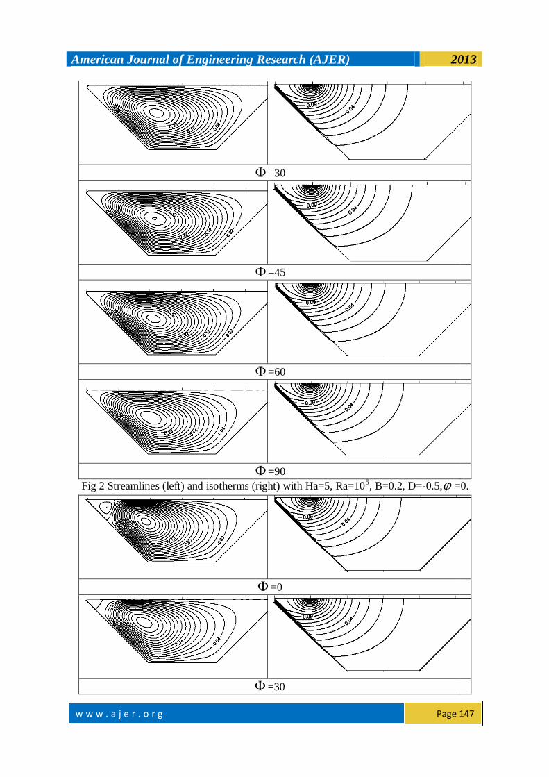
III. RESULTS AND DISCUSSION Metamorphosis of thermo-fluid fields have described. There exists a counter circulating cell in Fig. 2,
where the core of the vortex lays in the left upper region of the cavity near the heat source, D=-0.5, and
therefore fluid has crowded in the left half of the enclosure. As the inclination angle increases, the fluid motion
increases which mean the obvious effect of buoyancy force. Hydrodynamic boundary layer along all walls
except for the right inclined sidewall. Isotherms are polarized in the left-upper corner. Therefore the thermal
boundary layer is very small in the inclined sidewall. It's observed stratification for temperature field. The effect of magnetic force is multiple with buoyancy force because they experience in the same direction. For inclination
angle greater than 45ͦ the flow tends to stretch diagonally. Fig. 3 shows the nano case; the hydro-field for
circulating cell has been zoned from the extreme left-upper corner due to the existence of nanoparticles through
the fluid, and the geometric attributes for this corner. It can be observed a week rotation clockwise has been
formed as a counter effect of duple governing force which producing the circulating cells extensively regions in
American Journal of Engineering Research (AJER) 2013
w w w . a j e r . o r g
Page 144
the cavity. So in this corner the viscous force is prominent. As the inclination angle increases, the resultant force decays because the buoyancy force is not being still work at the same destination of magnetic force. Thereby the
effect of viscous force has been destroyed. Increasing of the inclination angle the primary circulation cell are
stretching diagonally until it is becoming 90 where the magnetic force is perpendicular to buoyancy force. The
buoyancy force gets the flow move upward for away from the left-upper corners. On other hand, Ha generates
the viscous diffusion flow. These two phenomena make three circulating cells, the strength of them increases as
flow moves toward the right side. Flow comes from the cold wall to hot wall thereby diffusion currents are
overwhelmed by convection currents. The extreme left portion resulting good thermal performance, while the
extreme right region represents diffusion dominated zone where the motion is very strong since it's only
subjected to the normal magnetic field. It's noticed that there are two circulating cells in the ends which are in
the anti-clockwise direction, so that the circulating cell entrapped with them is in the clockwise direction. By
continue, the primary vortex grasps with other circulating cells. All of them expand paralleling to the secondary diagonal direction. Temperature keeps invariant during the round. Until the angle = 90, a huge disturbance
happens because of the appearance of diffusion heat transfer in the right part. The effects of heat source
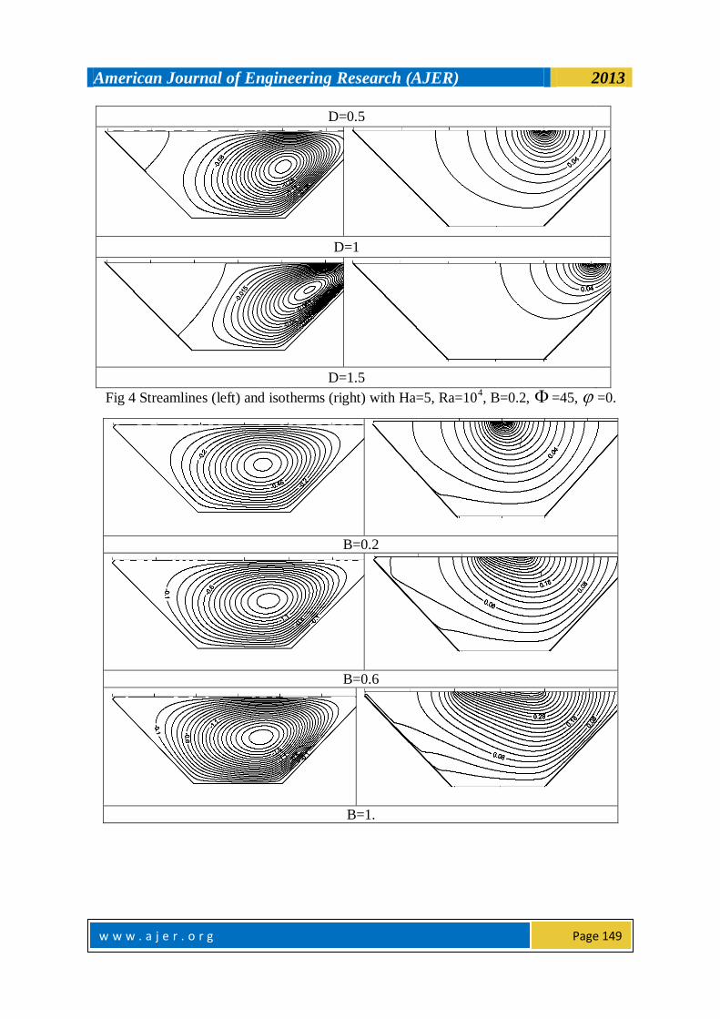
location, heat source length and Hartmann number are showed in Figs. 4-6. The core of vortex follows D's
movement it is noticeable there is no similarity even if the heat source location in the bisection way because Ha
effect is regular along the top surface. In the same direction the effect buoyancy force acting from the source. It
is observed the similarity between each pairs of corresponding cases such as the two cases of D=-0.5 and 1.5. As
B increases the circulating cell has stretched horizontally and then the hydrodynamic boundary layer decreases.
Also the stratification in the isotherms increases indicating the strong influence of viscous diffusion. It is
observed that the temperature gradients increase as B increases at the vicinity of tilted left surface, where the
inclination angle =45 the thermal boundary layers very tinny along this surface invoking the supremacy of
convection heat transfer. For low Ha the motion is regularly at whole the cavity where a singular circulating cell and counter clockwise direction of motion. As Ha increases the circulating cell squeezes toward the nearest side
to the heat source. Because the intensity of magnetic force increases the resulting recirculation cell experience
the retarding motion. The diffusion current starts to dominate the convection current. As the magnetic force
triumphs over buoyancy force, the core of the vortex shifts toward the source. By increasing of Ha, a core of
circulating cell is shifted resulting formulation a stagnation point in the left upper corner. Also, temperature
lines switch toward the left side decelerating the formulation of thermal boundary layer. At Ha =100,
multicellaur formulation is appeared in the cavity. The weaker zone is shifted and the major vortex is entrapped
by two minor vortices so the diffusion flow becomes more prominent. The oscillating thermal boundary layer
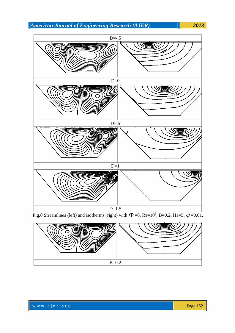
represents the dominancy of diffusion heat flux. Figs. 7-9 display the effect of Ha, D and B in the nano case.
The symmetry in streamlines in Fig. 7 which appears two contour rotating vortices is due to symmetrical
dynamic flow and symmetrical boundary condition. At the absence of magnetic force the strength of circulating
cell is high relatively. Thermal boundary layer in the left side has more effect than the right side. As Ha increases the core of vortex stretched toward the source. Increasing Ha also leads to increase temperature
gradient and increase heat transfer rate consequently. Comparing with Fig. 4, considering the change in the
inclination angle, it is observed the relation between D and buoyancy force which appears its effect in
generation of vortices and the relation between D and temperature gradient reflecting the effective range of
diffusion heat transfer and size of thermal boundary layer. Variation of B explains the link between heat source
and the idiosyncratic attributes for thermo-flow application. As B increases the fluid motion tends to take the
anti-clockwise direction, therefore at B=2 there exists three cores. Two of them are produced by the stretch
happening in the counter circulation cell. For isotherms, the changing of B is related to the stratification of
temperature lines which ensures the dominancy of diffusion heat transfer. For moderate value of Ha=5, Figs 10
and 11 show the effect of solid volume fraction in various titled positions. By studying the scenario of change
horizontally, it confirms the argument of Fig. 2 the vertically studying, for the familiar position the increase of solid volume fraction get the flow more be symmetric. But for other inclination positions, it is observed a
shipment of core of vortices are generated and rigorous develop of plumage has been happened. The left
circulating cell decays and minor vortices have grasped to the major vortex which expanded diagonally.
Isotherms tend to cluster in the right portion as the inclination angle increases respect to the buoyancy force. The
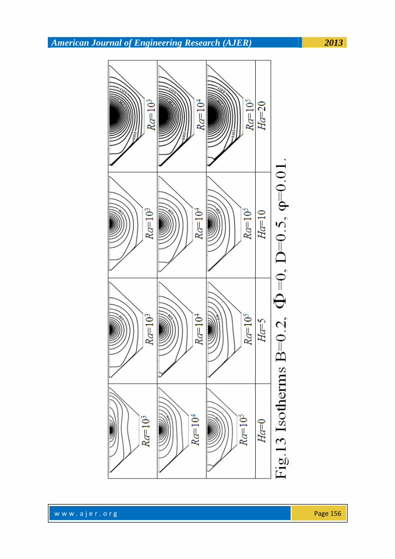
vertical scenario shows that the increase of the angle leads to increase the diffusion current. For Figs. 12 and 13,
increases in Ha result in increase the polarization of the core of circulating cells toward the source, which
appears by horizontal change. Also it leads to increase the diffusion current adding to convection current. The
vertical scenario shows at the absence of magnetic force, increasing in Ra makes the flow unsymmetrical. Also
it strengthens the counter circulation cell and increases the convection heat transfer. Fig. 14 shows the
symmetrical behavior of local Nusselt number. As B decreases, the heat transfer rate increases, moreover, the
temperature gradients increases. Fig. 15 offers the symmetrical behavior of Nu –local- around the D, which
strengthens the heat transfer rate. Figs 16 and 17 ensure the previous argument about Figs. 14 and15. It shows
American Journal of Engineering Research (AJER) 2013
w w w . a j e r . o r g
Page 145
the effect of inclination angle on the heat transfer generally. Fig. 18 deduces that Num slightly decreases as the solid volume fraction increases except for B=0.2 because the greatest value of temperature gradient and heat
transfer rate. It is showed that Num increases as B decreases. Fig. 19 and 20 show the average Nusselt number
increases with the solid volume fraction for constant parameters' motion except for Ha which decreases the Num.
When Ra is the only variable in the Num- relation, Num increases linearly with and Ra enhances it. As the
inclination angle increases in Fig. 21, Num increases. The relation between Num- is irregular; however Num
increases with linearly for the small angles. Num increases with Ra as an exponentially behavior in Fig. 22 where Ra changes in logarithm way. Ha do not affect Num for small Ra; otherwise, it has a huge effect for high
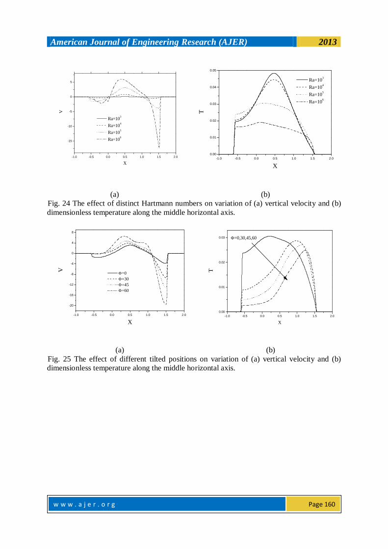
Ra values. Figs. 23 -27 show relations V-X and temperature-X. Vertical velocity tends to be symmetrical for {
, B , Ha} changes, while temperature tends to be more smooth for both Ha and Ra changes. At X=0.5, the maximum value for velocity when Ha=0 while for temperature when Ha=20. The global maximum temperature
at B=2.
IV. CONCLUSION Magneto-hydrodynamics (MHD) is the science of the motion of electrically conducting fluids under the
influence of applied magnetic forces. A numerical study has been achieved for the natural convection cooling of a heat source mounted inside a trapezoidal cavity filled by Cu–water nanofluid in the presence of vertical
magnetic field. It was observed that the increasing in inclination angle enhances the buoyancy force while the
effect of viscous force has been vanished. At maximum inclination angle, the left part of the enclosure has good
thermal performance but the right represents diffusion dominated zone where the motion is subject to the
magnetic force. Increase of B produces a strong influence of viscous diffusion. In the left inclined surface, once
the inclination angle equal 45 the flow invokes the supremacy of convection heat transfer. As Ha increases the
temperature gradients increases, hence heat transfer rate increases. At Ha=100 the oscillating thermal boundary
layer refers to the dominancy of diffusion heat flux. There is a strong relation between the heat transfer location
and the temperature gradient in nanofluid which reflects the effective range of diffusion heat transfer and size of
thermal boundary layer. It is noticed that as the solid volume fraction increases the diffusion currents increase.
But as Ra increases the convection currents increase specially in the absence of magnetic force.
REFERENCES [1] M.A.H. Mamun, Md.T. Islam, Md.M. Rahman, Natural convection in a porous trapezoidal enclosure with
[2] J. Bear, Dynamics of Fluids in Porous Media, American Elsevier publishing company, Inc., New York,
1972.
[3] D.A. Nield, A. Bejan, Convection in Porous Media, 3rd ed., Springer, New York, 2006.
[4] Transport Phenomena in Porous Media, D.B. Ingham, I. Pop (Eds.), Elsevier, Oxford, 2005. [5] Hanbook of Porous Media, K. Vafai (Ed.), 2nd ed., Taylor & Francis, Boca Raton, 2005.
[6] Emerging Topics in Heat and Mass Transfer in Porous Media, P. Vadasz (Ed.), Springer, New York,
2008.
[7] I. Pop, D.B. Ingham, Convective Heat Transfer: Mathematical and Computational Modeling of Viscous
Fluids and Porous Media, Pergamon, Oxford, 2001.
[8] H. B´enard, Formation p´eriodique de centres de giration `a l’arri`ere d’un obstacle en mouvement, C. R.
Acad. Sci., 147, pp. 839–842, 1908.
[9] L. Rayleigh, On convection currents in a horizontal layer of fluid when the higher temperature is on the
underside, Philos. Mag., 6(32), pp. 529–546, 1946.
[10] H. Jeffreys, Some cases of instabilities in fluid motion, P. Roy. Soc. Lond. A Mat., 118, pp. 195–208,
1928.
[11] N.H. Saied, I. Pop, Non-Darcy natural convection in a square cavity filled with a porous media, Fluid Dyn. Res., 36, pp. 35–43, 2005.
[12] F.Marcondes, J.M.Medeiros, J.M. Gurgel, Numerical analysis of natural convection in cavities with
variable porosity, Numer. Heat Tr. A-Appl., 40, pp. 403–420, 2001.
[13] P. Nithiarasu, K.N. Seetharamu, T. Sundararajan, Numerical investigation of buoyancy driven flow in a
fluid saturated non-Darcian porous medium, Int. J. Heat Mass Tran., 42, pp. 1205–1215, 1999.
[14] E. Baez, A. Nicolas, 2D natural convection flows in tilted cavities: Porous media and homogeneous
fluids, Int. J. Heat Mass Tran., 49, pp. 4773–4785, 2006.
[15] A.C. Baytas, I. Pop, Natural convection in a trapezoidal enclosure filled with a porous medium, Int. J.
Eng. Sci., 39, pp. 125–134, 2001.
American Journal of Engineering Research (AJER) 2013
w w w . a j e r . o r g
Page 146
[16] F.C. Lai, I. Pop, Natural Convection in a Truncated Circular Sector of Porous Medium, Int. Commun. Heat Mass, 17, pp. 801–811, 1990.
[17] S. Mahmud, R.A. Fraser, Magnetohydrodynamic free convection and entropy generation in a square
porous cavity, Int. J. Heat Mass Tran., 47, pp. 3245–3256, 2004.
[18] Cho SUS. Enhancing thermal conductivity of fluids with nanoparticles. ASME Fluids Eng Division
1995;231:99–105.
[19] Xuan YM, Li Q. Heat transfer enhancement of nanofluid. Int J Heat Fluid Flow 2000;21:58–64.
[20] Khanafer K, Vafai K, Lightstone M. Buoyancy-driven heat transfer enhancement in a two-dimensional
enclosure utilizing nanofluids. Int J Heat Mass Transfer 2003;46:3639–53.
[21] Mahmoudi AH, Shahi M, Raouf A, Ghasemian A. Numerical study of natural convection cooling of
horizontal heat source mounted in a square cavity filled with nanofluid. Int Commun Heat Mass Transfer
2010;37:1135–41. [22] Oztop HF, Abu-Nada E. Numerical study of natural convection in partially heated rectangular enclosures
filled with nanofluids. Int J Heat Fluid Flow 2008;29:1326–36.
[23] Aminossadati SM, Ghasemi B. Enhanced natural convection in an isosceles triangular enclosure filled
with a nanofluid. Comput Math Appl 2011;61:1739–53.
[24] Natarajan E, Basak T, Roy S. Natural convection flows in a trapezoidal enclosure with uniform and non-
uniform heating of bottom wall. Int J Heat Mass Transfer 2008;51:747–56.
[25] Basak T, Roy S, Singh A, Balakrishnan AR. Natural convection flows in porous trapezoidal enclosures
with various inclination angles. Int J Heat Mass Transfer 2009;52:4612–23.
[26] Varol Y, Oztop HF, Pop I. Natural convection in right-angle porous trapezoidal enclosure partially cooled
from inclined wall. Int Commun Heat Mass Transfer 2009;36:6–15.
[27] Saleh H, Roslan R, Hashim I. Natural convection heat transfer in a nanofluid-filled trapezoidal enclosure. Int J Heat Mass Transfer 2011;54: 194–201.
[28] Nasrin R, Parvin S. Investigation of buoyancy-driven flow and heat transfer in a trapezoidal cavity filled
with water–Cu nanofluid. Int Commun Heat Mass Transfer 2012;39:270–4.
[29] Bejan A. Entropy generation through heat and fluid flow. New York: Wiley; 1982.
[30] Mahmoudi AH, Shahi M, Talebi F. Entropy generation due to natural convection in a partialy open cavity
with a thin heat source subjected to a nanofluid. Numer Heat Transfer A 2012;61:283–305.
[31] Shahi M, Mahmoudi AH, Honarbakhsh Raouf A. Entropy generation due to natural convection cooling of
a nanofluid. Int Commun Heat Mass Transfer 2011;38:972–83.
[32] M. Mahmoodi, S. M. Hashemi, Numerical study of natural convection of a nanofluid in C-shaped
enclosures, International Journal of Thermal Sciences 55 (2012) 76-89.
[33] Brinkman HC. The viscosity of concentrated suspensions and solutions. J. Chem. Phys. 1952;20:571–81.
[34] Maxwell JC. A treatise on electricity and magnetism. 2nd ed. Cambridge: Oxford University Press; 1904. p. 435–41.
[35] M.A. Mansour, A.J. Chamkha, R.A. Mohamed , M.M. Abd El-Aziz , S.E. Ahmed, MHD natural
convection in an inclined cavity filled with a fluid saturated porous medium with heat source in the solid
phase. Nonlinear Anal. 15(2010) 55–70.
[36] T. Grosan , C. Revnic, I. Pop, D.B. Ingham, Magnetic field and internal heat generation effects on the
free convection in a rectangular cavity filled with a porous medium. Int. J. Heat Mass Transf.
52(2009)1525–1533.
[37] B.V. Ratish Kumar, P.V.S.N. Murthy, P. Singh, Free convection heat transfer from an isothermal wavy
surface in a porous enclosure. Int. J. Numer. Meth. Fluids 28(1998) 633–661.
[38] M. Haajizadeh , A.F. Ozguc and C.L. Tien, Natural convection in a vertical porous enclosure with
internal heat generation, Int. J. Heat Mass Transfer, 27(1984) 1893–190.
=0
American Journal of Engineering Research (AJER) 2013
w w w . a j e r . o r g
Page 147
=30
=45
=60
=90
Fig 2 Streamlines (left) and isotherms (right) with Ha=5, Ra=105, B=0.2, D=-0.5, =0.
=0
=30
American Journal of Engineering Research (AJER) 2013
w w w . a j e r . o r g
Page 148
=45
=60
=90
Fig 3 Streamlines (left) and isotherms (right) with Ha=5, Ra=104, B=0.2, D=-0.5, =0.01.
D=-0.5
D=0
American Journal of Engineering Research (AJER) 2013
w w w . a j e r . o r g
Page 149
D=0.5
D=1
D=1.5
Fig 4 Streamlines (left) and isotherms (right) with Ha=5, Ra=104, B=0.2, =45, =0.
B=0.2
B=0.6
B=1.
American Journal of Engineering Research (AJER) 2013
w w w . a j e r . o r g
Page 150
B=2.
Fig 5 Streamlines (left) and isotherms (right) with Ha=5, Ra=104, D=0.5, =45, =0.
Ha=0
Ha=5
Ha=10
Ha=50
Ha=100
American Journal of Engineering Research (AJER) 2013
w w w . a j e r . o r g
Page 151
Fig 6 Streamlines (left) and isotherms (right) with B=0.2, Ra=104, D=0.5, =45, =0.
Ha=0
Ha=5
Ha=10
Ha=20
Fig.7 Streamlines (left) and isotherms (right) with =0, Ra=105, B=0.2, D=0.5, =0.01.s
American Journal of Engineering Research (AJER) 2013
w w w . a j e r . o r g
Page 152
D=-.5
D=0
D=.5
D=1
D=1.5
Fig.8 Streamlines (left) and isotherms (right) with =0, Ra=105, B=0.2, Ha=5, =0.01.
B=0.2
American Journal of Engineering Research (AJER) 2013
w w w . a j e r . o r g
Page 153
B=0.6
B=1
B=2
Fig.9 Streamlines (left) and isotherms (right) with =0, Ra=105, D=0.5, Ha=5, =0.01.
American Journal of Engineering Research (AJER) 2013
w w w . a j e r . o r g
Page 154
American Journal of Engineering Research (AJER) 2013
w w w . a j e r . o r g
Page 155
American Journal of Engineering Research (AJER) 2013
w w w . a j e r . o r g
Page 156
American Journal of Engineering Research (AJER) 2013
w w w . a j e r . o r g
Page 157
-0.4 -0.2 0.0 0.2 0.4 0.6 0.8 1.0 1.2 1.4
2.0
2.5
3.0
3.5
4.0
4.5
5.0
5.5
6.0
Nu
s
X
B=0.2
B=0.6
B=1
B=2
Fig. 14 Variation of local Nusselt number
along the heat source for different heat
source lengths.
-0.4 -0.2 0.0 0.2 0.4 0.6 0.8 1.0 1.2 1.4
2.0
2.5
3.0
3.5
4.0
4.5
5.0
5.5
6.0
Nu
s
X
D=-0.5
D=0
D=0.5
D=1
Fig. 15 Variation of local Nusselt
number along the heat source for
different heat source locations.
-0.4 0.0 0.4 0.8
7
8
9
10
11
12
13
Nu
s
X
D=-0.5,0,0.5,1
Fig. 16 Variation of local Nusselt
number along the heat source for
different heat source lengths.
-0.4 -0.2 0.0 0.2 0.4 0.6 0.8 1.0 1.2 1.4
3
4
5
6
7
8
9
10
11
12
13
Nu
s
X
B=0.2
B=0.6
B=1
B=2
=60
Fig. 17 Variation of local Nusselt number along
the heat source for different heat source lengths.
American Journal of Engineering Research (AJER) 2013
w w w . a j e r . o r g
Page 158
0.00 0.05 0.10 0.15 0.20
4
5
6
7
8
9
N
um
B=0.2
B=0.6
B=1
B=2
=60
Fig. 18 The effect of distinct heat source lengths
on variation of average Nusselt number with
solid volume fraction.
0.00 0.05 0.10 0.15 0.20
5.0
5.5
6.0
6.5
7.0
7.5
8.0
8.5
9.0
9.5
10.0
Nu
m
Ha=0
Ha=5
Ha=10
Ha=20
Fig. 19 The effect of distinct Hartmann
numbers on variation of average Nusselt
number with solid volume fraction.
0.00 0.05 0.10 0.15 0.20
5
6
7
8
9
10
Nu
m
Ra=103
Ra=104
Ra=105
Ra=106
Fig. 20 The effect of distinct Raylei-gh
numbers on variation of average Nuss-elt
number with solid volume fraction.
0.00 0.05 0.10 0.15 0.20
4
6
8
10
12
14
16
18
Nu
m
=0
=30
=45
=60
Fig. 21 The effect of various tilted positions on
variation of average Nusselt number with solid
volume fraction.
American Journal of Engineering Research (AJER) 2013
w w w . a j e r . o r g
Page 159
104
105
106
5
6
7
8
9
10
N
um
Ra
Ha=0
Ha=5
Ha=10
Ha=20
Fig. 22 The effect of
distinct Hartmann numbers
on variation of average
Nusselt number for
different Rayleigh
numbers.
-1.0 -0.5 0.0 0.5 1.0 1.5 2.0
-12
-10
-8
-6
-4
-2
0
2
4
V
X
Ha=0
Ha=5
Ha=10
Ha=20
-1.0 -0.5 0.0 0.5 1.0 1.5 2.0
0.00
0.01
0.02
0.03
0.04
T
X
Ha=0
Ha=5
Ha=10
Ha=20
(a) (b)
Fig. 23 The effect of distinct Hartmann numbers on variation of (a) vertical velocity and (b)
dimensionless temperature along the middle horizontal axis.
American Journal of Engineering Research (AJER) 2013
w w w . a j e r . o r g
Page 160
-1.0 -0.5 0.0 0.5 1.0 1.5 2.0
-15
-10
-5
0
5
V
X
Ra=103
Ra=104
Ra=105
Ra=106
-1.0 -0.5 0.0 0.5 1.0 1.5 2.0
0.00
0.01
0.02
0.03
0.04
0.05
T
X
Ra=103
Ra=104
Ra=105
Ra=106
(a) (b)
Fig. 24 The effect of distinct Hartmann numbers on variation of (a) vertical velocity and (b)
dimensionless temperature along the middle horizontal axis.
-1.0 -0.5 0.0 0.5 1.0 1.5 2.0
-20
-16
-12
-8
-4
0
4
8
V
X
=0
=30
=45
=60
-1.0 -0.5 0.0 0.5 1.0 1.5 2.0
0.00
0.01
0.02
0.03
T
X
=0,30,45,60
(a) (b)
Fig. 25 The effect of different tilted positions on variation of (a) vertical velocity and (b)
dimensionless temperature along the middle horizontal axis.
American Journal of Engineering Research (AJER) 2013
w w w . a j e r . o r g
Page 161
-1.0 -0.5 0.0 0.5 1.0 1.5 2.0
-16
-12
-8
-4
0
4
V
X
B=0.2
B=0.6
B=1
B=2
-1.0 -0.5 0.0 0.5 1.0 1.5 2.0
0.00
0.04
0.08
0.12
0.16
0.20
T
X
B=0.2,0.6,1,2
(a) (b)
Fig. 26 The effect of distinct heat source lengths on variation of (a) vertical velocity and (b)
dimensionless temperature along the middle horizontal axis.
-1.0 -0.5 0.0 0.5 1.0 1.5 2.0
-4
-3
-2
-1
0
1
2
3
V
X
=0
=0.05
=0.1
=0.15
=0.2
-1.0 -0.5 0.0 0.5 1.0 1.5 2.0
0.00
0.01
0.02
0.03
T
X
=0
=0.05
=0.1
=0.15
=0.2
(a) (b)
Fig. 27 The effect of distinct solid volume fractions on variation of (a) vertical velocity and
(b) dimensionless temperature along the middle horizontal axis.