Ak MITSUBISHI HEAVY INDUSTRIES, LTD. 16-5, KONAN 2-CHOME, MINATO-KU TOKYO, JAPAN April 3, 2012 Document Control Desk U.S. Nuclear Regulatory Commission Washington, DC 20555-0001 Attention: Mr. Jeffrey A. Ciocco Docket No. 52-021 MHI Ref: UAP-HF-12078 Subject: MHI's Amended Responses to US-APWR DCD RAI No.574-4633 Revision 2 (SPP 10.02.03) Reference: 1) "Request for Additional Information No. 574-4633 Revision 2, SRP Section: 10.02.03 - Turbine Rotor Integrity, Application section Tier 2 FSAR Section 10.2.3," dated April 20, 2010. 2) "US-APWR DC SER-Chapter 10 (MIL111990458)," dated August 9, 2011 With this letter, Mitsubishi Heavy Industries, Ltd. ("MHI") transmits to the U.S. Nuclear Regulatory Commission ("NRC") a document entitled "MHI's Amended Responses to Request for Additional Information No. 574-4633 Revision 2" Enclosed are the MHI's amended responses to 4 RAIs contained within Reference 1. As indicated in the enclosed materials, this document contains information that MHI considers proprietary, and therefore should be withheld from public disclosure pursuant to 10 C.F.R. § 2.390 (a)(4) as trade secrets and commercial or financial information which is privileged or confidential. A non-proprietary version of the document is also being submitted with the information identified as proprietary redacted and replaced by the designation "[ ]". This letter includes a copy of the proprietary version (Enclosure 2), a copy of the non-proprietary version (Enclosure 3), and the Affidavit of Yoshiki Ogata (Enclosure 1) which identifies the reasons MHI respectfully requests that all materials designated as "Proprietary" in Enclosure 2 be withheld from public disclosure pursuant to 10 C.F.R. § 2.390 (a)(4). Please contact Mr. Joseph Tapia, General Manager of Licensing Department, Mitsubishi Nuclear Energy Systems, Inc. if the NRC has questions concerning any aspect of the submittals. His contact information is below. Sincerely, Yoshiki Ogata, Director-APWR Promoting Department Mitsubishi Heavy Industries, LTD. 0
Transcript
AkMITSUBISHI HEAVY INDUSTRIES, LTD.
16-5, KONAN 2-CHOME, MINATO-KUTOKYO, JAPAN
April 3, 2012
Document Control DeskU.S. Nuclear Regulatory CommissionWashington, DC 20555-0001
Attention: Mr. Jeffrey A. CioccoDocket No. 52-021
MHI Ref: UAP-HF-12078
Subject: MHI's Amended Responses to US-APWR DCD RAI No.574-4633 Revision 2(SPP 10.02.03)
Reference: 1) "Request for Additional Information No. 574-4633 Revision 2, SRP Section:10.02.03 - Turbine Rotor Integrity, Application section Tier 2 FSAR Section10.2.3," dated April 20, 2010.
2) "US-APWR DC SER-Chapter 10 (MIL111990458)," dated August 9, 2011
With this letter, Mitsubishi Heavy Industries, Ltd. ("MHI") transmits to the U.S. NuclearRegulatory Commission ("NRC") a document entitled "MHI's Amended Responses toRequest for Additional Information No. 574-4633 Revision 2"
Enclosed are the MHI's amended responses to 4 RAIs contained within Reference 1.
As indicated in the enclosed materials, this document contains information that MHI considersproprietary, and therefore should be withheld from public disclosure pursuant to 10 C.F.R. §2.390 (a)(4) as trade secrets and commercial or financial information which is privileged orconfidential. A non-proprietary version of the document is also being submitted with theinformation identified as proprietary redacted and replaced by the designation "[ ]".
This letter includes a copy of the proprietary version (Enclosure 2), a copy of thenon-proprietary version (Enclosure 3), and the Affidavit of Yoshiki Ogata (Enclosure 1) whichidentifies the reasons MHI respectfully requests that all materials designated as "Proprietary"in Enclosure 2 be withheld from public disclosure pursuant to 10 C.F.R. § 2.390 (a)(4).
Please contact Mr. Joseph Tapia, General Manager of Licensing Department, MitsubishiNuclear Energy Systems, Inc. if the NRC has questions concerning any aspect of thesubmittals. His contact information is below.
Sincerely,
Yoshiki Ogata,Director-APWR Promoting DepartmentMitsubishi Heavy Industries, LTD.
0
Enclosure:
1. Affidavit of Yoshiki Ogata
2. MHI's Amended Responses to Request for Additional Information No. 574-4633 Revision 2(proprietary version)
3. MHI's Amended Responses to Request forAdditional Information No. 574-4633 Revision 2(non-proprietary version)
CC: J. A. CioccoJ. Tapia
Contact InformationJoseph Tapia, General Manager of Licensing DepartmentMitsubishi Nuclear Energy Systems, Inc.1001 19th Street North, Suite 710Arlington, VA 22209E-mail: joseph [email protected]: (703) 908 - 8055
Enclosure 1Docket No. 52-021
MHI Ref: UAP-HF-12078
MITSUBISHI HEAVY INDUSTRIES, LTD.
AFFIDAVIT
I, Yoshiki Ogata, state as follows:
1. I am Director, APWR Promoting Department, of Mitsubishi Heavy Industries, LTD ("MHI"),and have been delegated the function of reviewing MHI's US-APWR documentation todetermine whether it contains information that should be withheld from public disclosurepursuant to 10 C.F.R. § 2.390 (a)(4) as trade secrets and commercial or financialinformation which is privileged or confidential.
2. In accordance with my responsibilities, I have reviewed the enclosed document entitled"MHI's Amended Responses to Request for Additional Information No. 574-4633 Revision2" dated April 2012, and have determined that portions of the document containproprietary information that should be withheld from public disclosure. Those pagescontaining proprietary information are identified with the label "Proprietary" on the top ofthe page and the proprietary information has been bracketed with an open and closedbracket as shown here "[ ]". The first page of the document indicates that allinformation identified as "Proprietary" should be withheld from public disclosure pursuantto 10 C.F.R. § 2.390 (a)(4).
3. The information identified as proprietary in the enclosed document has in the past been,and will continue to be, held in confidence by MHI and its disclosure outside the companyis limited to regulatory bodies, customers and potential customers, and their agents,suppliers, and licensees, and others with a legitimate need for the information, and isalways subject to suitable measures to protect it from unauthorized use or disclosure.
4. The. basis for holding the referenced information confidential is that it describes theunique design by MHI for performing the turbine rotors design of the US-APWR.
5. The referenced information is being furnished to the Nuclear Regulatory Commission("NRC") in confidence and solely for the purpose of information to the NRC staff.
6. The referenced information is not available in public sources and could not be gatheredreadily from other publicly available information. Other than through the provisions inparagraph 3 above, MHI knows of no way the information could be lawfully acquired byorganizations or individuals outside of MHI.
7. Public disclosure of the referenced information would assist competitors of MHI in theirdesign of new nuclear power plants without incurring the costs or risks associated withthe design of the subject systems. Therefore, disclosure of the information contained inthe referenced document would have the following negative impacts on the competitiveposition of MHI in the U.S. nuclear plant market:
A. Loss of competitive advantage due to the costs associated with development ofturbine rotor materials.
B. Loss of competitive advantage of the US-APWR created by benefits of informationof turbine rotor materials specification.
I declare under penalty of perjury that the foregoing affidavit and the matters stated thereinare true and correct to the best of my knowledge, information and belief.
Executed on this 3rd day of April, 2012.
Yoshiki Ogata,Director-APWR Promoting DepartmentMitsubishi Heavy Industries, LTD.
Docket No. 52-021MHI Ref: UAP-HF-12078
Enclosure 3
UAP-HF-12078Docket Number 52-021
MHI's Amended Responses to Request for Additional InformationNo. 574-4633 Revision 2
Revision 2 to the US-APWR FSAR revised Section 10.2.3.1 to delete the reference to grade C(Classes 5, 6 and 7). Therefore the FSAR no longer specifies the type of material (Grade orClassification) from ASTM A470. Since there are different Grades and Classifications in ASTMA470 that have different chemical compositions and mechanical properties, the NRC staffcannot assess the acceptability of the material concerning the turbine rotor integrity asdescribed in SRP 10.2.3, and whether the turbine rotor material is bounded by the turbinemissile analysis. Therefore, the specific Grade and Classification of ASTM A470 material orreference to the specific material ordering requirements should be included in the US-APWRFSAR that is bounded by the turbine missile analysis.
ANSWER:MHI deleted the reference to grade C (Classes 5, 6 and 7) in Revision 2 of US-APWR FSARSection 10.2.3.1 in accordance with NRC requirement of letter dated May 20 2009, a responseto RAI No. 324-1997, Question 03.05.01.03-1.
Additional NRC Comment (Open Item 10.2.3-1):
The response is incomplete, since ASTM A470 with no specific grade/class no longer specifiesthe type of material. Discuss;
1) What type of material shall be applied to the US-APWR LP rotor?
2) How do the material properties relate to those used in the turbine missile analysis?
3) Specific LP rotor material name and the details of chemical composition and mechanicalproperties of the rotor shall be placed in this RAI response. In addition, specific LP rotormaterial name shall also be placed in the turbine missile analysis reports (MUAP-07028)so that the acceptance criteria of as-built rotor are bounded by the mechanical propertiesused in the turbine missile analysis (MUAP-07028).
10.02.03-1
MHI Response to Additional NRC Comment
I. MHI material type and the relation to the material properties used in the turbinemissile analysis
1) Type of material to be applied to the US-APWR LP rotor:
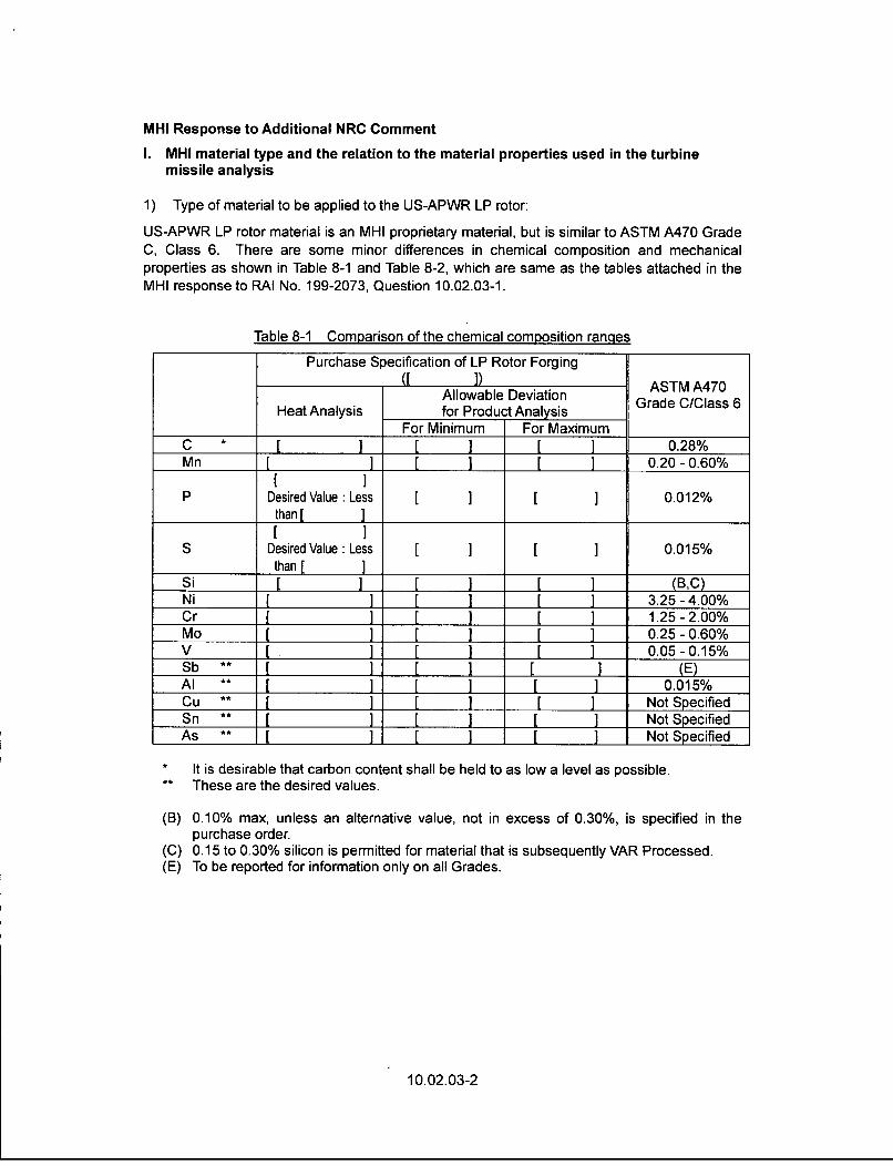
US-APWR LP rotor material is an MHI proprietary material, but is similar to ASTM A470 GradeC, Class 6. There are some minor differences in chemical composition and mechanicalproperties as shown in Table 8-1 and Table 8-2, which are same as the tables attached in theMHI response to RAI No. 199-2073, Question 10.02.03-1.
Table 8-1 Comparison of the chemical composition ranges
Purchase Specification of LP Rotor Forging() ASTM A470
Allowable Deviation aST A470Heat Analysis for Product Analysis
For Minimum For MaximumC * ] ] 0.28%Mn ] J J 0.20-0.60%
[I IP Desired Value :Less [ ] [ ] 0.012%
than[[ I
S Desired Value: Less [ ] [ ] 0.015%than[ ]
Si [ ] [ _ [ ] (B,C)Ni I ] . _ __ [_ ] 3.25-4.00%Cr [ ] [_ _ [ ] 1.25-2.00%Mo _ _ _ I ] [ ] 0.25-0.60%V A ] I ] [ 1 0.05-0.15%Sb ** A L [ _ L. ].(E)Al ** A ] [ 1 [ 0.015%Cu ** [ I _ J Not SpecifiedSn ** [1 [ ] [ ] Not SpecifiedAs ** [ L [ _ [ Not Specified
• It is desirable that carbon content shall be held to as low a level as possible.
•* These are the desired values.
(B) 0.10% max, unless an alternative value, not in excess of 0.30%, is specified in thepurchase order.
(C) 0.15 to 0.30% silicon is permitted for material that is subsequently VAR Processed.(E) To be reported for information only on all Grades.
Tensile Test (0.2% offset)Elongation Min.17%Reduction of Area Min.50%Absorbed Energyat 21-27 deg C Min.61J
Charpy Test 50% FATT Max.-7 deg CUpper ShelfEnergy Level [_]_-
2) Relation between material properties of the purchase specification and those used in theturbine missile analysis:
Specified minimum yield strength in MHI purchase specification of the LP rotor materialI ] is explicitly used in the turbine missile analysis (MUAP-07028 (R1)) and actual yieldstrength of the as-built rotors will be confirmed. 50 percent fracture appearance transitiontemperature (FATT) of [ ] and Upper Shelf Energy Level of [ ], which arealso discussed in the turbine missile analysis (MUAP-07028 (R1)) will be confirmed on theas-built rotors as well as yield strength to confirm that K1c applied to the above turbine missileanalysis is adequate.
II. Placing specific LP rotor material name
MHI agrees to place the LP rotor material name [ ] in this RAI response (Table 8-1 andTable 8-2) and turbine missile analysis (MUAP-07028). The turbine missile analysis report(MUAP-07028) Section 2 DESIGN FEATURES will be revised as follows:
2.0 DESIGN FEATURES
A typical integral rotor is shown in Figure 2-1. A major advantage of this design is the eliminationof the disc bores and keyways. Rotors with shrunk-on discs have peak stresses around thelocations where the discs are shrunk-on and keyed to the shaft. The elimination of thesestructures has shifted the location of peak stress from the keyways to blade fastening regions atthe rim of the rotor, whose local stress is much lower than that of the shrunk-on discs. Sincecracks are likely to occur in high stressed regions, reduction of the peak stress throughout therotor significantly contributes to the reduction of the rotor burst probability.
In addition to lower local stress throughout the rotor, the integral structure also has the benefit ofreduced average tangential stress of the discs and this fact allows us to apply lower yieldstrength material with traditional safety margins remaining as they are. The integral rotorforgings of the 3.5% Ni-Cr-Mo-V alloy steel [ I are heat-treated to obtain minimum yieldstrengths of [ ], maximum FATT of [ 1, and minimum upper shelf energy ofI I depending upon the requirements of the particular application. Many years ofexperience and testing the rotor material have demonstrated better ductility, toughness andresistance to stress corrosion cracking at a lower yield strength. These benefits can beimportant factors to reduce the possibility of turbine missile generation.
10.02.03-3
Impact on DCD
Refer to "Impact on DCD" in the response to RAI 574-4633, Question 10.02.03-10,RAI10.2.3-10.
Impact on R-COLA
There is no impact on the R-COLA.
Impact on S-COLA
There is no impact on the S-COLA.
Impact on PRA
There is no impact on the PRA.
Impact on Technical/Topical Report
Refer to above I1. (Placing specific LP rotor material name) of MHI Response to Additional NRCComment for Additional NRC Comment (Open Item 10.2.3-1).
10.02.03-4
RESPONSE TO REQUEST FOR ADDITIONAL INFORMATION
03/30/2012
US-APWR Design Certification
Mitsubishi Heavy Industries
Docket No. 52-021
RAI NO.:
SRP SECTION:
APPLICATION SECTION:
DATE OF RAI ISSUE:
NO. 574-4633
10.02.03 - Turbine Rotor Integrity
Application Section: Tier 2 FSAR Section 10.2.3
4/20/2010
QUESTION NO.: 10.02.03-9, RAI 10.2.3-9
In a letter dated March 10, 2009, the response to RAI No. 199-2073, Question 10.02.03-2provided acceptance criteria for the 50% FATT and Charpy V-notch energy which do not meetthe acceptance criteria of -18*C (0°F) and 8.3 kg-m (60 ft-lbs), respectively, as provided in SRPSections 10.2.3 (paragraphs 1Ilb and I1.1c). Therefore, provide a discussion on why thematerial properties for the 50% FATT and Charpy V-notch energy provided in the response toRAI No. 199-2073, Question 10.02.03-2 ensures that the turbine rotor has adequate fracturetoughness during startup and normal operating temperatures.
ANSWER:It is confirmed in the rotor design that the rotor has adequate fracture toughness.The fracture analysis done in the design includes determining the stresses in the rotorresulting from rotation, steady-state thermal loads and transient thermal loads from startupand stop. Fracture toughness Kic used in the fracture analysis is introduced by specifiedmechanical properties of the rotor material, 50%FATT and Upper Shelf Absorbed Energy,with Begley-Logsdon method.
Figure 9-1 Begley-Logsdon method
10.02.03-5
Additional NRC Comment (Open Item 10.2.3-2):
The acceptance criteria provided in the response to RAI 199-2073, Question 10.2.3-2, for the50 percent FATT and Charpy V-notch energy do not meet the acceptance criteria of -18 'C(0 'F) and 8.3 kg-m (60 ft lbs or 81 J), respectively, which are provided in SRP Sections 10.2.3(Paragraphs IIl.b and I1.1c).
Therefore, the applicant is requested to provide a discussion on why the material properties forthe 50 percent FATT and Charpy V-notch energy of [ ] and [ ] respectivelyprovided in the response to RAI 199-2073, Question 10.2.3-2, is sufficient to ensure that theturbine rotor has adequate fracture toughness during startup and normal operatingtemperatures.
SRP section 10.2.3 paragraph 11.lb and c require the Charpy V-Notch energy and FATT curvesto be well defined to use the Begley-Logsdon method. The applicant is requested to provideNRC with the confirmation that The Charpy V-Notch energy and FATT curves are well definedfor the material which is to be used for the US-APWR LP turbine rotors.
MHI Response to Additional NRC Comment
I. Minimum requirement for the 50 percent FATT and Charpy V-notch energy
It is true that criteria for the 50 percent FATT and Charpy V-notch (Cv) energy in MHI purchasespecification is equivalent to those specified in ASTM A470 Grade C, Class 6, which is not asconservative as SRP Criteria as shown in the following table.
Table 9A-1 Comparison of mechanical property requirements
Unit MHI purchase ASTM A470 Grade C SRP 10.2.3
specification Class 6
50 percent FATT Max. °C [ ] -7 -18
C, energy Min. J at RT [ ] 61 81
RT: Room Temperature
But the following reasons show that above requirements of MHI purchase specification(I ]) are conservative enough to obtain thefracture toughness (Klc) to secure the probability of the turbine missile ejection less than 1x10.5
per year, which is the criteria for unfavorably oriented turbine.
(1) K1c applied to the turbine missile analysis (MUAP-07028 (R1)) was obtained based on themost conservative C, energy and 50 percent FATT specified in the rotor purchasespecification through Begley-Logsdon Method. Therefore, the K1c applied to the turbinemissile analysis and the rotor purchase specification are being kept consistent with eachother.
(2) Kic of [ ] which is actually used in the turbine missile analysisincludes [ ] safety margin against the above calculated K1c of [ ](refer to Figure 9A-1).
(3) Actual obtainable K1c at the center bore core region of the actual full integral LP rotors isgreater than 200 ksi-in11 2 (220 MPa.m'1 2), while much lower Kic of [was applied to the turbine missile analysis (refer to Figure 9A-1).
10.02.03-6
Figure 9A-1 Relation between Kic used in missile analysis and actual obtainable Kicbased on MHI Purchase Specification
Notes on the above figures;
(1) Actual Fracture toughness (Kic) at the center bore core of the full integral rotors are significantly higher than
that used in the turbine missile analysis [ ].
(2) This fact ensures that the turbine missile ejection probability can be kept low enough compared to the criteria
in the SRP, even if MHI purchase specification does not comply with the requirement of SRP 10.2.3 in regard
to 50 percent FATT and C. energy.
I1. Application of the Begley-Logsdon method to the LP rotor material [ ]
(1) Sample of measured "Percent of brittle fracture" and "Absorbed energy" of the materialI ], which is to be applied to US-APWR LP rotors, are given in Figure 9A-2.
(2) Those parameters and their approximate curves clearly show prominenttemperature-dependent characteristics.
(3) FATT and Upper-shelf energy can be well (clearly) defined by the approximate curves.The material of [ ] surely satisfies the conditions stipulated in the SRP section10.2.3 paragraph I1.1b for the application of Begley-Logsdon method to estimate actualKic of manufactured LP rotors.
(4) Measuring method of those parameters;
" Confirm temperature-dependent properties by measuring the brittle fractureappearance rate and the absorbed energy at different temperatures more than eightpoints, and draw approximate curves.
10.02.03-7
v" 50%FATT is determined by this approximate curves and absorbed energy isdetermined by approximate curve at both room temperature (approx. 259C) andtemperature at the value of 0% of brittle fracture
Figure 9A-2 Example of measured "Percent of brittle fracture" and "Absorbedenergy" of the LP rotor material [ ]
Notes on the above figure;
(1) Percent brittle fracture; Brittle fracture appearance/Area of fracture surface
(2) Absorbed energy; The energy to fracture a test specimen in a Charpy test
In a letter dated March 10, 2009, MHI provided a response to RAI No. 199-2073, Question10.02.03-2, stated that the tensile and charpy testing will be performed on five specimens fromthe outer periphery of the turbine rotor. For a bored rotor, additional tensile and Charpy testingwill be performed from three specimens on the interior bore periphery of the turbine rotor.However, the staff notes that Revision 2 of the US-APWR FSAR did not include the number ofspecimens to be tested as provided in the response to RAI No. 199-2073, Question 10.2.3-2. Inaddition, the staff notes that neither MHI's response to RAI No. 199-2073, Question 10.02.03-2provided in a letter dated March 10, 2009, nor Section 10.2.3.2 of the US-APWR FSAR,Revision 2, Tier 2 provides the method of calculating the fracture toughness value for theturbine rotor material.SRP Section 10.2.3 (paragraph 11.2) lists four acceptable methods for obtaining the fracturetoughness properties. Therefore, the staff requests that the USAPWR FSAR be revised to:
a. Include the number of test specimens as stated in its response to RAI No. 199-2073,Question 10.02.03-2
b. Include the test method and fracture toughness acceptance criteria that will be used forthe turbine rotor design.
ANSWER:a. The numbers of test specimens will be added to FSAR section 10.2.3.
The location of test coupons is shown as Figure 10-1.b. The Charpy test criteria will be added to FSAR section 10.2.3.
The Acceptance criteria for the Charpy test are shown as Table 10-1.
10.02.03-9
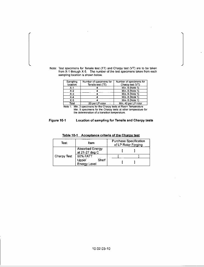
Note: Test specimens for Tensile test (TT) and Charpy test (VT) are to be takenfrom X-1 through X-5. The number of the test specimens taken from eachsampling location is shown below.
Sampling Number of specimens for Number of specimens forlocation Tensile test (TT) Charpy test (VT)
X-1 4 Min. 8 (Note 1)X-2 4 Min. 8 (Note 1)X-3 4 Min. 8 (Note 1)X-4 4 Min. 8 (Note 1)X-5 4 Min. 8 (Note 1)
Total 20 per LP rotor Min. 40 per LP rotorMnto 1" RAin 2 cnorimonc fMr *lofho 'hrr~t lff *f Dnrtnr Tomnnoratl. r
KIM y1 Ric. 'A o med e flo r the Char tests~ atOL R-m m~~l =• rll f=LMin. 5 specimens for the Charpy tests at other temperature for
the determination of a transition temperature.
Location of sampling for Tensile and Charpy testsFigure 10-1
Table 10-1 Acceptance criteria of the Charpy test
Purchase Specificationof LP Rotor Forging
Absorbed Energyat 21-27 deg C
Charpy Test 50% FATTUpper ShelfEnergy Level [_ ]
10.02.03-10
Additional NRC Comment (Open Item 10.2.3-3):
Regarding the locations of the test specimens and the material properties of the internal regionsfor a non-bored rotor, the applicant stated in its response to RAI 199-2073, Question 10.2.3-2,that the tensile and Charpy testing will be performed on five coupons from the outer periphery ofthe turbine rotor. For a bored rotor, additional tensile and Charpy testing will be performed fromthree coupons on the interior bore periphery of the turbine rotor. The staff finds the number ofspecimens acceptable since it meets the guidance provided in SRP 10.2.3.
However, the staff identifies that Revision 2 of the DCD should include the number of couponsand specimens to be tested as provided in the response to RAI 199-2073, Question 10.2.3-2.
MHI Response to Additional NRC Comment
The following sentence will be added in Revision 3 of the DCD:
Five coupons will be taken from one LP rotor. Four tensile test specimens and minimum eightCharpy V-notch (C,) test specimens, which includes minimum three C, test specimens at roomtemperature are cut out from each coupon.
Impact on DCD
The 1st paragraph of the US-APWR, Tier 2, Section 10.2.3.1 and the 1st paragraph of theUS-APWR, Tier 2, Section 10.2.3.2 will be revised as follows. (See attachment-I.)
10.2.3.1 Materials Selection
Fully integral turbine rotors are made from ladle refined, vacuum deoxidized Ni-Cr-Mo-V alloysteel by processes that maximize the cleanliness and toughness of the steel. The lowestpractical concentrations of residual elements are obtained through the melting process. The LPturbine rotor material is similar to ASTM A470, Grade C. Class 6 (Reference 10.2-5) asspecified in the turbine missile analysis (Reference 10.2-9). This material has the lowestfracture appearance transit temperatures (FATT) and the highest Charpy V-notch (C,) energiesobtainable on a consistent basis from water-quenched Ni-Cr-Mo-V material at the sizes andstrength levels used. Mechanical properties such as tensile strength, yield strength, elongation,reduction of area, absorbed energy at Charpy test at room temperature and 50 percent FATTare equal to or more conservative than those of ASTM A470, Grade C, Class 6. Charpy testsand tensile tests are conducted in accordance with ASTM, A370 (Reference 10.2-6). Fivecoupons will be taken from one LP rotor. Four tensile test specimens and minimum eightCharpy V-notch (C,) test specimens, which includes minimum three C, test specimens at roomtemperature are cut out from each coupon and tested in accordance with the requirement ofASTM A370 (Reference 10.2-6).
10.2.3.2 Fracture Toughness
Suitable material toughness is obtained through the use of materials described in Subsection10.2.3.1 to produce a balance of material strength and toughness to provide safety whilesimultaneously providing high reliability, availability, and efficiency during operation. Therestrictions on phosphorous n_, sulphur_(_S, aluminum_(.l), antimony (Sb), tin (Sn), Arsenic(As) and copper (Cu) in the specification for the rotor steel provide the appropriate balance ofmaterial strength and toughness. The absorbed energy and 50 percent FATT requirements areequal to or more rigorous than those given in ASTM A470, Grade C, Class 6.
In a letter dated March 10, 2009, MHI provided responses to RAI No. 199-2073, Questions10.02.03-2 and 10.02.03-5 concerning the integrity of a non-bored (solid) turbine rotor.
MHI response to RAI No. 199-2073, Questions 10.02.03-2 provided some material test resultcomparisons between the rotor outer periphery and the rotor center core so that the mechanicalproperties at the rotor center core can be evaluated using the material at the outer periphery ofthe turbine rotor. Based on this comparison, chemical composition and mechanical testing ofthe core for non-bored rotors would not be performed. The NRC staff notes that thecomparative material test results provided shows that the material at the center core of theturbine rotor has material properties that are less conservative (lower reduction of area, lowerimpact energy and higher 50 percent FATT temperature) than at the outer periphery, which isdue to the different solidification rates of this large component. Therefore, the materialproperties cannot be accurately and consistently determined using only test specimens from theouter periphery of the turbine rotor.
In its response to RAI No. 199-2073, Question 10.02.03-05, MHI stated that ultrasonicinspection of the turbine rotor will be performed prior to gashing (final outside peripherymachining) so that 100% ultrasonic inspection can be performed on the turbine rotor due to itsdrum shape.
However, it also states that as ultrasonic testing technology advances, potential defects at thecenter core region will be detected. Therefore, this implies that currently, ultrasonic inspection isnot capable of ensuring the integrity of non-bored turbine rotors at the center region.
Therefore, the integrity of non-bored turbine rotors cannot be verified, since the non-destructiveexaminations (pre-service and in-service volumetric inspections) are not capable of detectingdefects at the center core region, and destructive testing cannot be performed on non-boredrotors to confirm the material properties. Therefore, the non-bored rotor design should bedeleted from the US-APWR FSAR, or provide the following.-
Specific destructive testing that can confirm the material properties at the core region,and/or more extensive test results.
Specific non-destructive testing that can detect defects at the center core region, or providespecific in-service non-destructive examinations, including inspection types, inspectioninterval, acceptance criteria, etc. taking into consideration that material properties and thepresence of internal defects of the as-built turbine rotor cannot be confirmed.
10.02.03-13
Appropriate operating experience which justifies the integrity of the turbine rotor can bemaintained.
ANSWER:
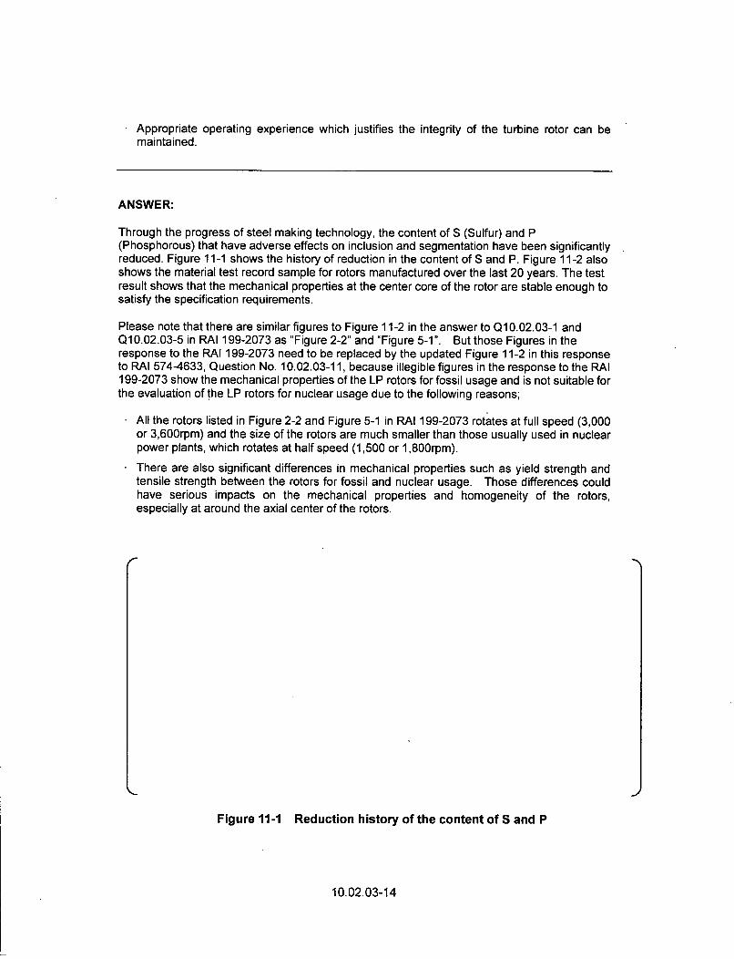
Through the progress of steel making technology, the content of S (Sulfur) and P(Phosphorous) that have adverse effects on inclusion and segmentation have been significantlyreduced. Figure 11-1 shows the history of reduction in the content of S and P. Figure 11-2 alsoshows the material test record sample for rotors manufactured over the last 20 years. The testresult shows that the mechanical properties at the center core of the rotor are stable enough tosatisfy the specification requirements.
Please note that there are similar figures to Figure 11-2 in the answer to Q1 0.02.03-1 andQ1 0.02.03-5 in RAI 199-2073 as "Figure 2-2" and "Figure 5-1 ". But those Figures in theresponse to the RAI 199-2073 need to be replaced by the updated Figure 11 -2 in this responseto RAI 574-4633, Question No. 10.02.03-11, because illegible figures in the response to the RAI199-2073 show the mechanical properties of the LP rotors for fossil usage and is not suitable forthe evaluation of the LP rotors for nuclear usage due to the following reasons;
All the rotors listed in Figure 2-2 and Figure 5-1 in RAI 199-2073 rotates at full speed (3,000or 3,600rpm) and the size of the rotors are much smaller than those usually used in nuclearpower plants, which rotates at half speed (1,500 or 1,800rpm).
There are also significant differences in mechanical properties such as yield strength andtensile strength between the rotors for fossil and nuclear usage. Those differences couldhave serious impacts on the mechanical properties and homogeneity of the rotors,especially at around the axial center of the rotors.
Figure 11-1 Reduction history of the content of S and P
10.02.03-14
r
Figure 11-2 Example of the LIP rotor material test result from last 20 yearrecord (all the rotors from A through G are for nuclear usage)
10.02.03-15
Through past improvement in ultrasonic testing technology, it is possible to detect smalldefects at the center of the rotor from the rotor periphery. As indicated in Figure 11-3, it isverified that ultrasonic inspection from the rotor periphery can reliably detect flawsI ] in length.
Table 11-1 shows examples of bore inspection record after long term operation. From thisrecord, it is confirmed that integrity of the turbine rotor has been maintained for more thanI I
All the units included in the Table 11 -1 are the ones for fossil usage and do not include the unitsfor nuclear usage. But please note that the low pressure turbines for unit A, C and D are ofhalf speed (1,800rpm) design like nuclear machines, and the rotor size and the materialproperties are same as that for the nuclear units. In addition, operating conditions such asinlet temperature and the number of starts/stops of fossil LP turbines is much severer thannuclear steam turbines in terms of imposed stresses on the rotors. It can be concluded thatoperating experience at fossil unit A, C and D bounds the experience at nuclear units.
10.02.03-16
Tablell-I Examples of bore inspection after operation (with -bored rotor)
Additional NRC: Comment (Open Item 10.2.3-4):
Based on the above, the turbine rotor can be either a bored or non-bored rotor design. Theapplicant also stated that the homogeneity and quality of the material at the center core of anon-bored rotor is ensured through the steel making process. In addition, in its response to RAI199-2073, Question 10.2.3-2, the applicant provided some material test result comparisonsbetween the rotor outer periphery and the rotor center core so that the mechanical properties atthe rotor center core can be evaluated using the material at the outer periphery of the turbinerotor. Therefore the applicant will not perform chemical composition and mechanical testing ofthe core for non-bored rotors.
The NRC staff notes that the comparative material test results provided show that the materialat the center core of the turbine rotor has material properties (lower reduction of area, lowerimpact energy and higher 50 percent FATT temperature) that are less conservative than at theouter periphery, which is due to the different solidification rates of this large component.Therefore, the material properties cannot be accurately and consistently determined using onlytest specimens from the outer periphery of the turbine rotor. Since the material properties dovary from the outer periphery to the internal center core, and the internal core of eachnon-bored as-built turbine rotor cannot be verified, the applicant should delete the non-boredturbine rotor from its design, or provide specific destructive testing and nondestructive testingtaking into consideration that the internal material properties and the presence of internaldefects of the as-built rotor cannot be confirmed. In addition, appropriate operating experienceshould be provided which justifies that the integrity of the rotor can be maintained.
MHI Response to Additional NRC Comment
1. Internal material of the non-bored LP rotors
1 . Reasons for use of non-bored rotor
MHI explained in the response to RAI No. 199-2073, Questions 10.02.03-2 and 10.02.03-5that non-bored rotors are to be applied to the US-APWR steam turbine due to the followingreasons:
10.02.03-17
(1) Inherent low tangential stress due to centrifugal forces at around the center of the rotor,(2) Advancement of steel making process which realizes homogeneity along radial line of
large size of LP rotors and mechanical properties at the center of the rotors can bereliably and stably kept within the limitation specified in MHI purchase specification.
2. Mechanical properties at the center of LP rotors;
Measured mechanical properties at the center bore core of the full integral rotor with drumdiameter of [ ] are shown in Figure 11A-1. The figure shows that all themean values of the mechanical properties ± 3a (99.7% reliability) are secured to satisfy theminimum required values of the purchase specification. As the LP rotor size of theUS-APWR is almost same as that of the rotors listed in Figure 11A-1 (this implies that thedrum diameter of the US-APWR LP rotors is expected to be the same as the maximumdiameter of the above range), it is concluded that the mechanical properties including"Absorbed Energy" and "50 percent FATT" are stably and reliably stay in the reliability higherthan 99.7 percent within the allowable ranges which is specified in the MHI purchasespecification.
3. Turbine missile probability
Due to the following three reasons, it was concluded that non-bored LP rotors keep theturbine missile probability less than the criteria specified in the SRP without destructivetesting at the center bore core:
(1) Inherent low tangential stress around the center of the rotor,(2) Mechanical properties at the rotor center stay in the reliability higher than 99.7 percent
within allowable range,(3) Fracture toughness (Kic) applied to the report "Probability of Missile Generation from
Low Pressure Turbines, MUAP-07028 (R1)" is [ ]. This K1c ofI ] is calculated based on the minimum requirement of the absorbedenergy and 50 percent FATT which can be achieved in the reliability higher than 99.7percent. Furthermore, additional safety margin of [ ] in the fracturetoughness (K1c) was applied to the LP turbine missile analysis (refer to Figure 9A-1 inthe MHI's amended response to the Question 10.02.03-9).
II. Inspection of the internal defects of non-bored LP rotors
As is explained in the DCD Section 10.2.3.3 "Preservice Inspection", each LP rotor forging issubject to a 100 percent volumetric examination (UT inspection). 100% UT inspection afterperiphery machining of the as-build rotors will be carried out to define the initial internaldefect size and location, including the ones around the center of the rotors. This UTinspection can detect the defects as small as [ at the center of therotors, while we assumed initial crack size is [ ] in the turbine missileanalysis conservatively to compensate for the possible inclined cracks. Therefore, the UTinspection from the rotor outer periphery as part of the preservice inspection is enough tokeep the turbine missile probability due to the low cycle fatigue less than the criteriaspecified in the SRP.
LP rotor outer surface is exposed to wet steam and material degradation could be occurreddue to corrosive environment, while center of the rotor is isolated from the steam and thereis no possibility of material degradation due to such environmental effects. In light of thisfact, we concluded that initial 100 percent UT inspection of the rotor and the turbine missileprobability analysis using the initial crack size and location of the as built-rotor is enough tosecure the turbine missile probability less than the criteria for the plant life time. Thismeans that it is not necessarily mandatory to do the UT inspection around the center of therotors during periodical inspection.
10.02.03-18
/F
Figure 11A-1 Test results of mechanical properties at the center bore core of fullintegral LP rotors for nuclear usage
(Refer to the Notes on the next page)
10.02.03-19
Notes for Figure 11A-1 (Figure of the previous pages):
Note 1: All the data in Figure 11A-1 is the one for center bore core of full integral rotorswith drum diameter between [ ] inches, while drum diameter of theUS-APWR LP rotors is expected to be almost same as the maximum of theabove range.
Note 2: Steel forging manufacturer of all the rotors listed in this figure is the one who aregoing to supply the LP rotor forgings for US-APWR.
Note 3: The positions of the test coupons from B1 through B3 are shown below:
Note 4: Blue dotted lines show the range of ±3a (99.7 percent reliability).All the mechanical properties including "Absorbed energy" and "50 percent FATT"are confirmed to be in the reliability higher than 99.7 percent.
Note 5: Minimum yield strength requirement of the LP rotors of Unit C and D changedfrom [ ] to [ ] to keep the Stress CorrosionCracking (SCC) sensitivity as low as possible depending on the safety margin ofthe rotors against centrifugal forces. Tensile strength of the same rotors alsoreduced along with the reduction of yield strength.
10.02.03-20
Impact on DCD
The 2 nd paragraph from the last of the US-APWR, Tier 2, Section 10.2.3.4 will be revised asfollows. (See attachment-1.)
The non-bored design of the high-pressure and low-pressure turbine rotor provides thenecessary design margin by virtue of its inherently lower centerline stress. Metallurgicalprocesses permit fabrication of the rotors without a center borehole. The use of solid rotorforgings was verified by an evaluation of the material removed from center-bored rotors fornuclear power plants. This evaluation demonstrated that the material at the center of the rotorssatisfied the rotor material specification requirements. Forgings for no-bore rotors are providedby suppliers who have been qualified based on bore material performance.
Impact on R-COLA
There is no impact on the R-COLA.
Impact on S-COLA
There is no impact on the S-COLA.
Impact on PRA
There is no impact on the PRA.
Impact on Technical/Topical Report
There is no impact on a Technical/Topical Report.
10.2.3-21
lattachmenUS-APWR Design Control Document10. STEAM ANDPOWER CONVERSION SYSTEM
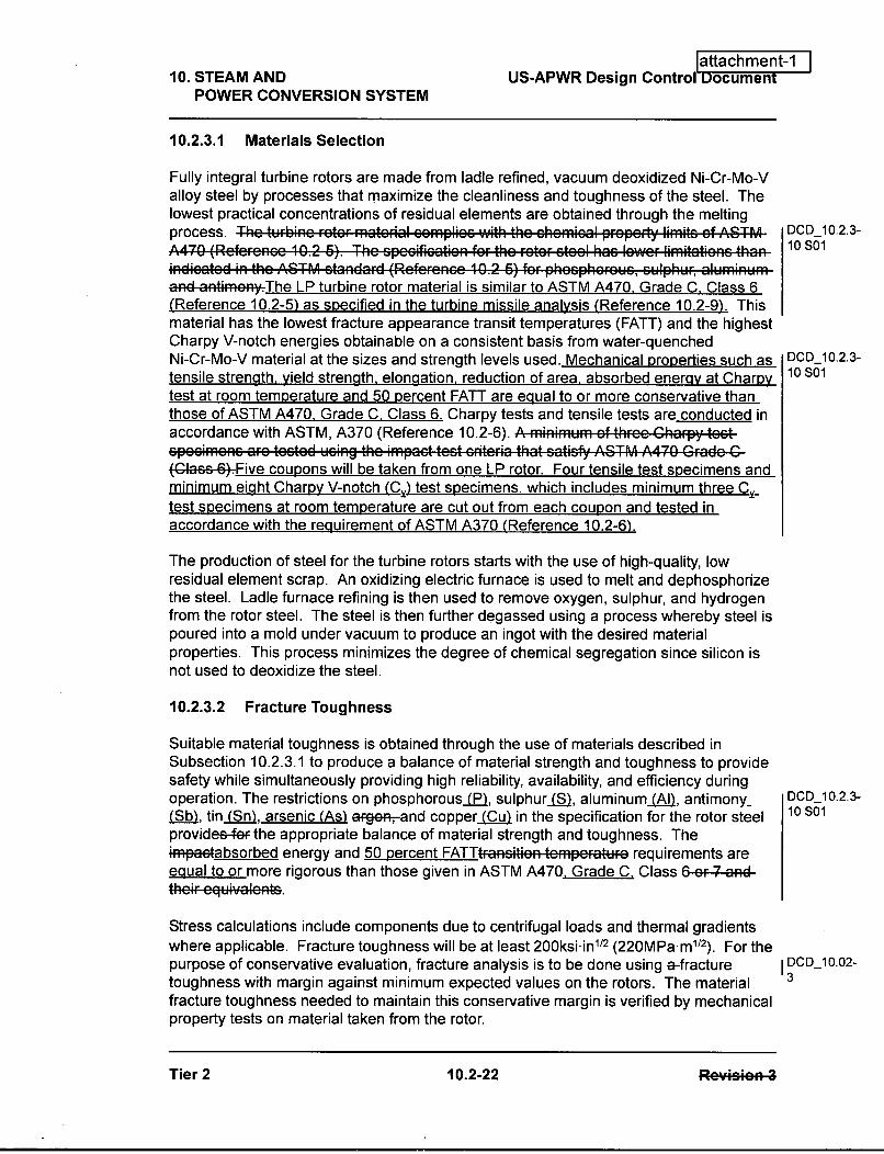
10.2.3.1 Materials Selection
Fully integral turbine rotors are made from ladle refined, vacuum deoxidized Ni-Cr-Mo-Valloy steel by processes that maximize the cleanliness and toughness of the steel. Thelowest practical concentrations of residual elements are obtained through the meltingprocess. The turbine rotor m.aterial .,mpliec with the chemicoal f.. prp.. limits.ef AST,..^A470 (Reference 10.2 6). The spccification for the rotor steel has lower limitationc thanindicaed inthe ASTM ctandard (Rofr,,nee 10.2 6) for phoephouew. , cu.phUr,, aluminuma3d a4tke.The LP turbine rotor material is similar to ASTM A470, Grade C. Class 6(Reference 10.2-5) as specified in the turbine missile analysis (Reference 10.2-9). Thismaterial has the lowest fracture appearance transit temperatures (FATT) and the highestCharpy V-notch energies obtainable on a consistent basis from water-quenchedNi-Cr-Mo-V material at the sizes and strength levels used. Mechanical properties such astensile strength, yield strength, elongation, reduction of area, absorbed energy at Charpytest at room temperature and 50 percent FATT are eaual to or more conservative thanthose of ASTM A470, Grade C. Class 6. Charpy tests and tensile tests are conducted inaccordance with ASTM, A370 (Reference 10.2-6). A Fminimum Of three "harpy testspecimenc arc tested using the impact test criteria that catisfy ASTM A470 Grade C(G'aee.6*•.Five coupons will be taken from one LP rotor. Four tensile test specimens andminimum eight Charpy V-notch (C,) test specimens, which includes minimum three C_test specimens at room temperature are cut out from each coupon and tested inaccordance with the requirement of ASTM A370 (Reference 10.2-6).
The production of steel for the turbine rotors starts with the use of high-quality, lowresidual element scrap. An oxidizing electric furnace is used to melt and dephosphorizethe steel. Ladle furnace refining is then used to remove oxygen, sulphur, and hydrogenfrom the rotor steel. The steel is then further degassed using a process whereby steel ispoured into a mold under vacuum to produce an ingot with the desired materialproperties. This process minimizes the degree of chemical segregation since silicon isnot used to deoxidize the steel.
10.2.3.2 Fracture Toughness
Suitable material toughness is obtained through the use of materials described inSubsection 10.2.3.1 to produce a balance of material strength and toughness to providesafety while simultaneously providing high reliability, availability, and efficiency duringoperation. The restrictions on phosphorousC(PI, sulphurS), aluminum (Al , antimony-( b), tin (Sn), arsenic (As) ar-ge, and copper _(ýu in the specification for the rotor steelprovidee-fe• the appropriate balance of material strength and toughness. The*Fpa Aabsorbed energy and 50 percent FATTtan-iti, n tempefatWre requirements areequal to or more rigorous than those given in ASTM A470, Grade C. Class 6 9F 7 -a•dthe ,-equivalents.
Stress calculations include components due to centrifugal loads and thermal gradientswhere applicable. Fracture toughness will be at least 200ksi-in112 (220MPa-m 1 2). For thepurpose of conservative evaluation, fracture analysis is to be done using a-fracturetoughness with margin against minimum expected values on the rotors. The materialfracture toughness needed to maintain this conservative margin is verified by mechanicalproperty tests on material taken from the rotor.
DCD_10.2.3-10 Sol
DCD_10.2.3-10S01
DCD_10.2.3-10S01
DCDI 10.02-13
Tier 2 10.2-22 Re~n4Tier 2 10.2-22 RpuageaR 2
10. STEAM AND US-APWR Design Control DocumentPOWER CONVERSION SYSTEM
The non-bored design of the high-pressure and low-pressure turbine rotor provides thenecessary design margin by virtue of its inherently lower centerline stress. Metallurgicalprocesses permit fabrication of the rotors without a center borehole. The use of solidrotor forgings was verified by an evaluation of the material removed from center-boredrotors for feswitnuclear power plants. This evaluation demonstrated that the material at DCD-10.2.3-
the center of the rotors satisfied the rotor material specification requirements. Forgings 11 SOl
for no-bore rotors are provided by suppliers who have been qualified based on borematerial performance.
All the low-pressure turbine rotating blades are attached to the rotor using christmas tree,side entry type root.
10.2.3.5 Inservice Inspection
The inservice inspection program for the LP turbine provides assurance that rotor flawsthat might lead to brittle failure of a rotor at speeds up to design speed will be detected.This inspection includes disassembly of the turbine at equal or less than 10-year intervalsduring plant shutdowns coincident with the inservice inspection schedule required byIWA-2430 of the 2007 Edition with 2008 Addenda of Section XI, Division 1 ASME Boiler &Pressure Vessel Code. Inspection of parts that are normally inaccessible when theturbine is assembled for operation (couplings, coupling bolts, turbine rotors, and lowpressure turbine blades) is conducted.
The maintenance and inspection program plan for the turbine assembly and valves isbased on turbine missile probability calculations, operating experience of similarequipment and inspection results. The turbine missile generation probability due to rotormaterial failure below design overspeed was submitted in Reference 10.2-9. Theanalysis of missile generation probability due to failure of the overspeed protectionsystem is used to determine turbine valve test frequency and is described in Reference10.2-10. The maintenance and inspection program includes the activities outlined below:
" This inspection consists of visual, surface, and volumetric examinations as indicatedbelow:
- Each rotor, stationary and the rotating blade path component is inspected visuallyand by magnetic particle testing on its accessible surfaces. Ultrasonic inspectionof the side entry blade grooves is conducted. These inspections are conducted atintervals equal or less than 10 years for both high-pressure and low-pressureturbines.
- A 100 percent surface examination of couplings and coupling bolts is performed.
- The fluorescent penetrant examination is conducted on nonmagneticcomponents.
At least one main steam stop valve, one main steam control valve, one reheat stopvalve, and one intercept valve are dismantled approximately every 4 years duringscheduled refueling or maintenance shutdowns. A visual and surface examination ofthe valve internals is conducted. If unacceptable flaws or excessive corrosion are