23
MIAC Operation and programming guide www.matrixtsl.com
MIACOperation and programming guide
www.matrixtsl.com

2 Copyright © 2012 Matrix Technology Solutions Ltd.
MIAC and the MIAC systemAbout this document
The MIAC (Matrix Industrial Automotive Controller) system allows the MIAC device to connect to modules which expand the I/O and capabilities of the MIAC. This document will give information on using the MIAC as a standalone device or as part of a MIAC system.
The MIAC system
The MIAC system allows users to rapidly set up complex electronic systems based around the MIAC device and its additional modules. Each of these individual modules contains a block of electronics you would typically find in an industrial control or data acquisition system.
Programming the MIAC system is typically done within Flowcode, the MIAC and all its modules are supported within the latest version, taking advantage of the simplicity and speed of programming within Flowcode.
The modules communicate with the ‘master’ MIAC via a series of CAN bus messages; all the low level CAN functions are handled by Flowcode allowing users with limited knowledge of CAN bus to be able to develop intricate systems.
This document will cover the technical details regarding the
MIAC and each of its individual modules, as well as information on using and programming the MIAC system within Flowcode.
Advantages of the MIAC system:
• Add up to 4 MIACs and 40 expansion modules• Simple to program with Flowcode’s drag and drop interface• Access to numerous subsystems via the expansion modules• No CAN programming experience necessary to develop a
network of MIACs and add-ons.• Compatible with a wide range of industrial sensors
Standalone MIAC
A MIAC device can still be used outside of a MIAC system, the main reasons would be; if there is an already existing CAN system or the additional I/O or the other advantages provided by the modules are not required.
Within Flowcode a user can select either the MIAC as a target device or a MIAC system, if a MIAC system is selected then the CAN bus protocol is preset by Flowcode and cannot be changed by the user.
If the user wishes to create their own CAN network then the MIAC should be selected as a standalone device.
3Copyright © 2012 Matrix Technology Solutions Ltd.
Introduction to the MIACWhat does it do?
MIAC (Matrix Industrial Automotive Controller) is an industrial grade control unit which can be used to control a wide range of different electronic systems. It has a number of applications in industrial and educational environments.
Benefits:
• Flexible and expandable• Easy to program with flowcharts, C or assembly code• Physically and electrically rugged
Features:
• Programmable from USB• Compatible with Flowcode and C• 8 digital or analogue inputs• 4 relay outputs, 4 motor outputs with speed control• 4 line LCD display and control keys• LabView and Visual Basic compatible
Description
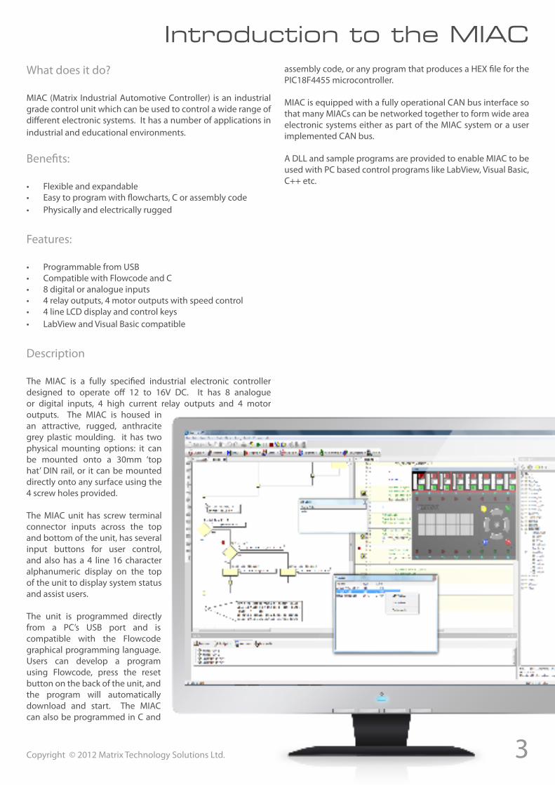
The MIAC is a fully specified industrial electronic controller designed to operate off 12 to 16V DC. It has 8 analogue or digital inputs, 4 high current relay outputs and 4 motor outputs. The MIAC is housed in an attractive, rugged, anthracite grey plastic moulding. it has two physical mounting options: it can be mounted onto a 30mm ‘top hat’ DIN rail, or it can be mounted directly onto any surface using the 4 screw holes provided.
The MIAC unit has screw terminal connector inputs across the top and bottom of the unit, has several input buttons for user control, and also has a 4 line 16 character alphanumeric display on the top of the unit to display system status and assist users.
The unit is programmed directly from a PC’s USB port and is compatible with the Flowcode graphical programming language. Users can develop a program using Flowcode, press the reset button on the back of the unit, and the program will automatically download and start. The MIAC can also be programmed in C and
assembly code, or any program that produces a HEX file for the PIC18F4455 microcontroller.
MIAC is equipped with a fully operational CAN bus interface so that many MIACs can be networked together to form wide area electronic systems either as part of the MIAC system or a user implemented CAN bus.
A DLL and sample programs are provided to enable MIAC to be used with PC based control programs like LabView, Visual Basic, C++ etc.
4 Copyright © 2012 Matrix Technology Solutions Ltd.
MIAC hardware
1 2
3 4
5 6
7
8 9
10
11
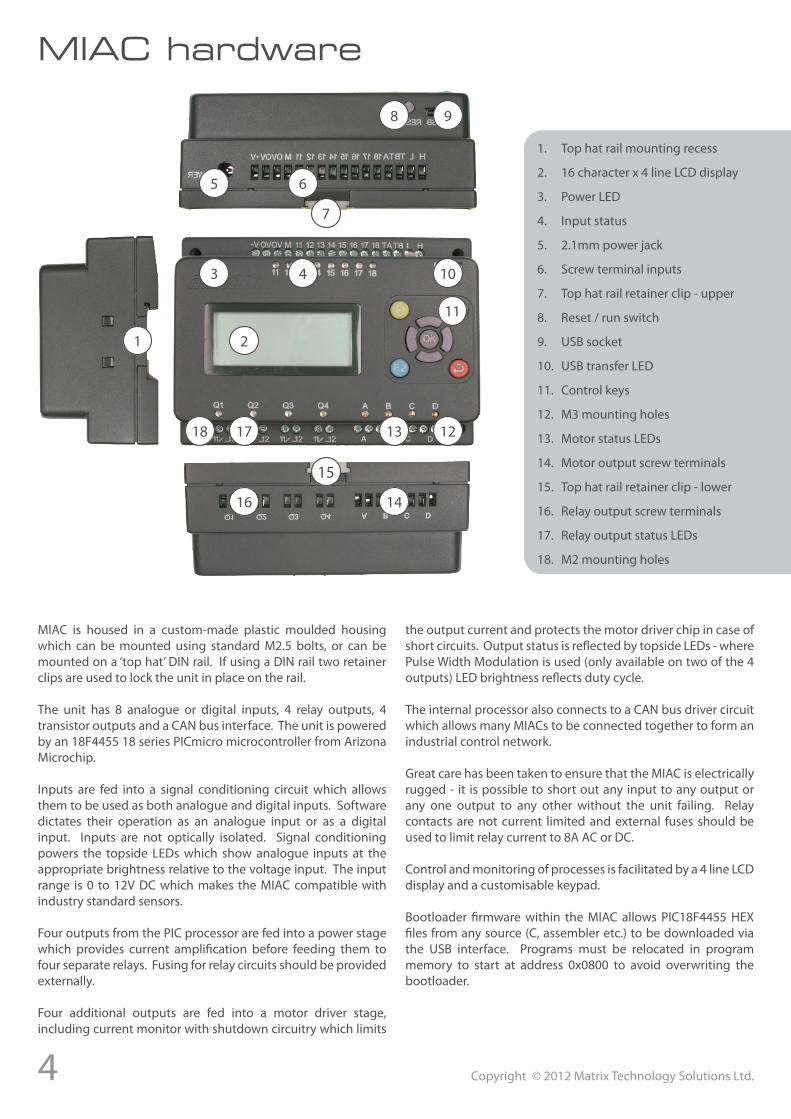
1. Top hat rail mounting recess
2. 16 character x 4 line LCD display
3. Power LED
4. Input status
5. 2.1mm power jack
6. Screw terminal inputs
7. Top hat rail retainer clip - upper
8. Reset / run switch
9. USB socket
10. USB transfer LED
11. Control keys
12. M3 mounting holes
13. Motor status LEDs
14. Motor output screw terminals
15. Top hat rail retainer clip - lower
16. Relay output screw terminals
17. Relay output status LEDs
18. M2 mounting holes
1213
14
15
16
1718
MIAC is housed in a custom-made plastic moulded housing which can be mounted using standard M2.5 bolts, or can be mounted on a ‘top hat’ DIN rail. If using a DIN rail two retainer clips are used to lock the unit in place on the rail.
The unit has 8 analogue or digital inputs, 4 relay outputs, 4 transistor outputs and a CAN bus interface. The unit is powered by an 18F4455 18 series PICmicro microcontroller from Arizona Microchip.
Inputs are fed into a signal conditioning circuit which allows them to be used as both analogue and digital inputs. Software dictates their operation as an analogue input or as a digital input. Inputs are not optically isolated. Signal conditioning powers the topside LEDs which show analogue inputs at the appropriate brightness relative to the voltage input. The input range is 0 to 12V DC which makes the MIAC compatible with industry standard sensors.
Four outputs from the PIC processor are fed into a power stage which provides current amplification before feeding them to four separate relays. Fusing for relay circuits should be provided externally.
Four additional outputs are fed into a motor driver stage, including current monitor with shutdown circuitry which limits
the output current and protects the motor driver chip in case of short circuits. Output status is reflected by topside LEDs - where Pulse Width Modulation is used (only available on two of the 4 outputs) LED brightness reflects duty cycle.
The internal processor also connects to a CAN bus driver circuit which allows many MIACs to be connected together to form an industrial control network.
Great care has been taken to ensure that the MIAC is electrically rugged - it is possible to short out any input to any output or any one output to any other without the unit failing. Relay contacts are not current limited and external fuses should be used to limit relay current to 8A AC or DC.
Control and monitoring of processes is facilitated by a 4 line LCD display and a customisable keypad.
Bootloader firmware within the MIAC allows PIC18F4455 HEX files from any source (C, assembler etc.) to be downloaded via the USB interface. Programs must be relocated in program memory to start at address 0x0800 to avoid overwriting the bootloader.
5Copyright © 2012 Matrix Technology Solutions Ltd.
Using MIAC with Flowcode
Using MIAC with Flowcode
MIAC has been developed in conjunction with Flowcode to provide an integrated development environment. Flowcode provides:• Macros to allow easy access to all the MIAC features• Simulation functions for most programs• Optimised program compilation • Single button programming of the MIAC• In Circuit Debugging (V4 only)
Getting started using Flowcode
Open a new flowchart in Flowcode. Select MIAC as the target device: Find and click on the MIAC icon in the component tool bar to
Selecting the MIAC as a target in Flowcode
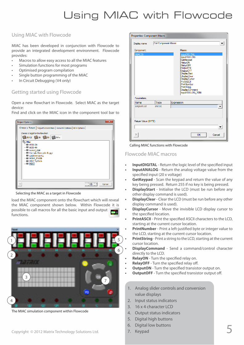
load the MIAC component onto the flowchart which will reveal the MIAC component shown below. Within Flowcode it is possible to call macros for all the basic input and output functions.
1
2
3
4
5
6
7
The MIAC simulation component within Flowcode
1. Analog slider controls and conversion value displays
2. Input status indicators3. 16 x 4 character LCD4. Output status indicators5. Digital high buttons6. Digital low buttons7. Keypad
Calling MIAC functions with Flowcode
Flowcode MIAC macros
• InputDIGITAL - Return the logic level of the specified input• InputANALOG - Return the analog voltage value from the
specified input (20 x voltage)• GetKeypad - Scan the keypad and return the value of any
key being pressed. Return 255 if no key is being pressed.• DisplayStart - Initialise the LCD (must be run before any
other display command is used).• DisplayClear - Clear the LCD (must be run before any other
display command is used).• DisplayCursor - Move the invisible LCD display cursor to
the specified location.• PrintASCII - Print the specified ASCII characters to the LCD,
starting at the current cursor location.• PrintNumber - Print a left-justified byte or integer value to
the LCD, starting at the current cursor location.• PrintString - Print a string to the LCD, starting at the current
cursor location.• DisplayCommand - Send a command/control character
directly to the LCD.• RelayON - Turn the specified relay on.• RelayOFF - Turn the specified relay off.• OutputON - Turn the specified transistor output on.• OutputOFF - Turn the specified transistor output off.
6 Copyright © 2012 Matrix Technology Solutions Ltd.
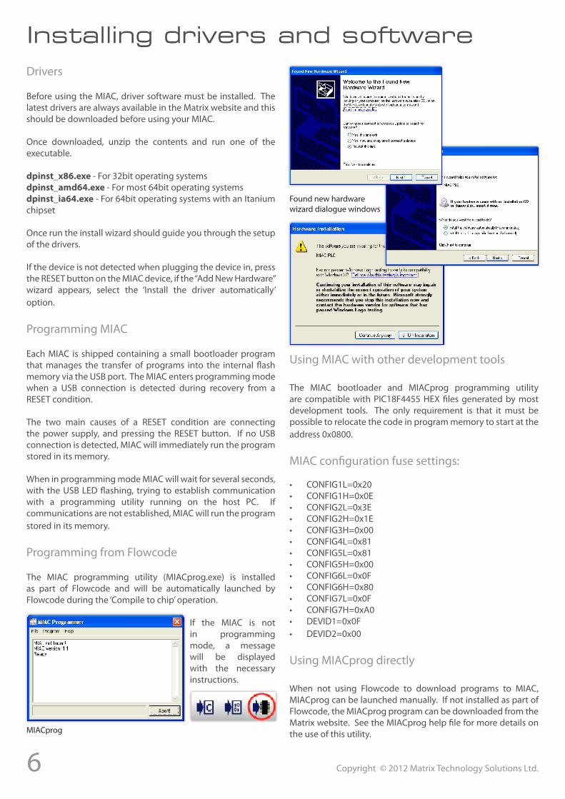
Installing drivers and softwareDrivers
Before using the MIAC, driver software must be installed. The latest drivers are always available in the Matrix website and this should be downloaded before using your MIAC.
Once downloaded, unzip the contents and run one of the executable.
dpinst_x86.exe - For 32bit operating systemsdpinst_amd64.exe - For most 64bit operating systemsdpinst_ia64.exe - For 64bit operating systems with an Itanium chipset
Once run the install wizard should guide you through the setup of the drivers.
If the device is not detected when plugging the device in, press the RESET button on the MIAC device, if the “Add New Hardware” wizard appears, select the ‘Install the driver automatically’ option.
Programming MIAC
Each MIAC is shipped containing a small bootloader program that manages the transfer of programs into the internal flash memory via the USB port. The MIAC enters programming mode when a USB connection is detected during recovery from a RESET condition.
The two main causes of a RESET condition are connecting the power supply, and pressing the RESET button. If no USB connection is detected, MIAC will immediately run the program stored in its memory.
When in programming mode MIAC will wait for several seconds, with the USB LED flashing, trying to establish communication with a programming utility running on the host PC. If communications are not established, MIAC will run the program stored in its memory.
Programming from Flowcode
The MIAC programming utility (MIACprog.exe) is installed as part of Flowcode and will be automatically launched by Flowcode during the ‘Compile to chip’ operation.
If the MIAC is not in programming mode, a message will be displayed with the necessary instructions.
MIACprog
Found new hardware wizard dialogue windows
Using MIAC with other development tools
The MIAC bootloader and MIACprog programming utility are compatible with PIC18F4455 HEX files generated by most development tools. The only requirement is that it must be possible to relocate the code in program memory to start at the address 0x0800.
MIAC configuration fuse settings:
• CONFIG1L=0x20• CONFIG1H=0x0E• CONFIG2L=0x3E• CONFIG2H=0x1E• CONFIG3H=0x00• CONFIG4L=0x81• CONFIG5L=0x81• CONFIG5H=0x00• CONFIG6L=0x0F• CONFIG6H=0x80• CONFIG7L=0x0F• CONFIG7H=0xA0• DEVID1=0x0F• DEVID2=0x00
Using MIACprog directly
When not using Flowcode to download programs to MIAC, MIACprog can be launched manually. If not installed as part of Flowcode, the MIACprog program can be downloaded from the Matrix website. See the MIACprog help file for more details on the use of this utility.
7Copyright © 2012 Matrix Technology Solutions Ltd.
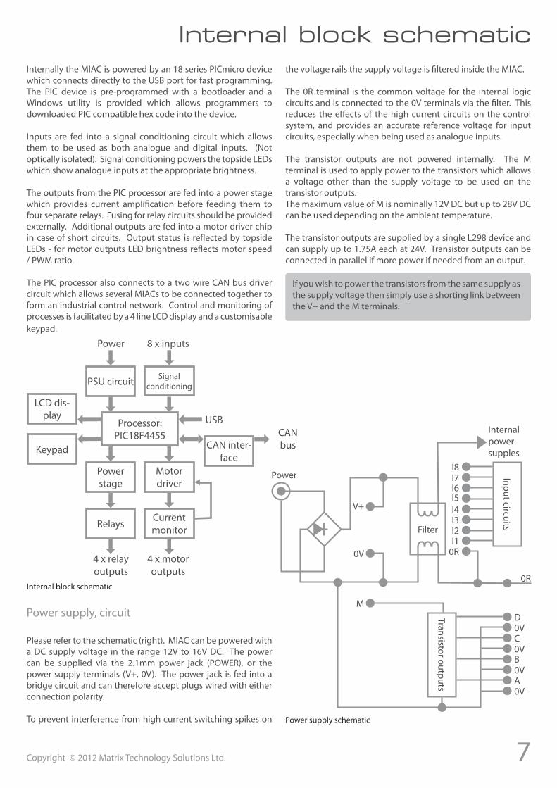
Internal block schematicInternally the MIAC is powered by an 18 series PICmicro device which connects directly to the USB port for fast programming. The PIC device is pre-programmed with a bootloader and a Windows utility is provided which allows programmers to downloaded PIC compatible hex code into the device.
Inputs are fed into a signal conditioning circuit which allows them to be used as both analogue and digital inputs. (Not optically isolated). Signal conditioning powers the topside LEDs which show analogue inputs at the appropriate brightness.
The outputs from the PIC processor are fed into a power stage which provides current amplification before feeding them to four separate relays. Fusing for relay circuits should be provided externally. Additional outputs are fed into a motor driver chip in case of short circuits. Output status is reflected by topside LEDs - for motor outputs LED brightness reflects motor speed / PWM ratio.
The PIC processor also connects to a two wire CAN bus driver circuit which allows several MIACs to be connected together to form an industrial control network. Control and monitoring of processes is facilitated by a 4 line LCD display and a customisable keypad.
Processor:PIC18F4455
PSU circuit Signal conditioning
Power stage
Motor driver
RelaysCurrent monitor
LCD dis-play
Keypad CAN inter-face
Power 8 x inputs
4 x relay outputs
4 x motor outputs
CAN bus
USB
Internal block schematic
Power supply, circuit
Please refer to the schematic (right). MIAC can be powered with a DC supply voltage in the range 12V to 16V DC. The power can be supplied via the 2.1mm power jack (POWER), or the power supply terminals (V+, 0V). The power jack is fed into a bridge circuit and can therefore accept plugs wired with either connection polarity.
To prevent interference from high current switching spikes on
the voltage rails the supply voltage is filtered inside the MIAC.
The 0R terminal is the common voltage for the internal logic circuits and is connected to the 0V terminals via the filter. This reduces the effects of the high current circuits on the control system, and provides an accurate reference voltage for input circuits, especially when being used as analogue inputs.
The transistor outputs are not powered internally. The M terminal is used to apply power to the transistors which allows a voltage other than the supply voltage to be used on the transistor outputs.The maximum value of M is nominally 12V DC but up to 28V DC can be used depending on the ambient temperature.
The transistor outputs are supplied by a single L298 device and can supply up to 1.75A each at 24V. Transistor outputs can be connected in parallel if more power if needed from an output.
If you wish to power the transistors from the same supply as the supply voltage then simply use a shorting link between the V+ and the M terminals.
Power supply schematic
Power
V+
0V
I8I7I6I5I4I3I2I1
0R
0R
Internal power supples
Input circuits
Filter
M
Transistor outputs
D0VC0VB0VA0V
8 Copyright © 2012 Matrix Technology Solutions Ltd.
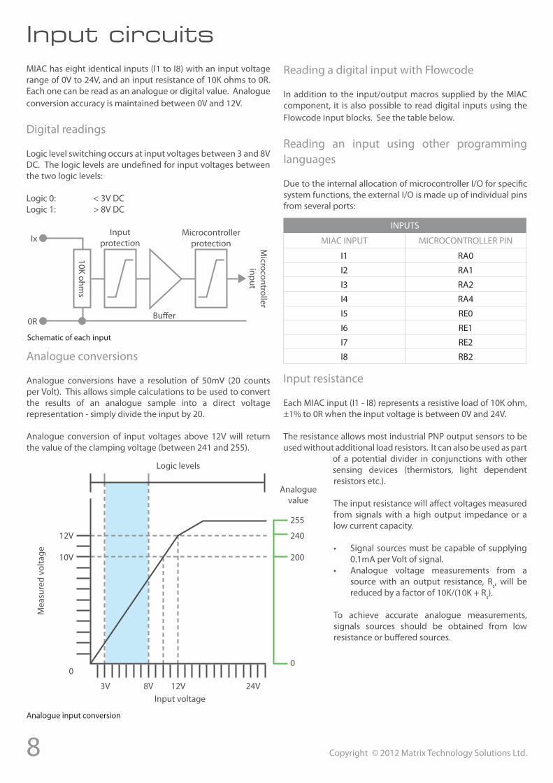
Input circuitsMIAC has eight identical inputs (I1 to I8) with an input voltage range of 0V to 24V, and an input resistance of 10K ohms to 0R. Each one can be read as an analogue or digital value. Analogue conversion accuracy is maintained between 0V and 12V.
Digital readings
Logic level switching occurs at input voltages between 3 and 8V DC. The logic levels are undefined for input voltages between the two logic levels:
Logic 0: < 3V DCLogic 1: > 8V DC
Ix
0R
10K ohms
Buffer
Input protection
Microcontroller protection M
icrocontroller input
Schematic of each input
Analogue conversions
Analogue conversions have a resolution of 50mV (20 counts per Volt). This allows simple calculations to be used to convert the results of an analogue sample into a direct voltage representation - simply divide the input by 20.
Analogue conversion of input voltages above 12V will return the value of the clamping voltage (between 241 and 255).
Analogue input conversion
Logic levels
Mea
sure
d vo
ltage
Input voltage
Analogue value
12V
10V
0
3V 8V 12V 24V
255
240
200
0
Reading a digital input with Flowcode
In addition to the input/output macros supplied by the MIAC component, it is also possible to read digital inputs using the Flowcode Input blocks. See the table below.
Reading an input using other programming languages
Due to the internal allocation of microcontroller I/O for specific system functions, the external I/O is made up of individual pins from several ports:
INPUTS
MIAC INPUT MICROCONTROLLER PIN
I1 RA0
I2 RA1
I3 RA2
I4 RA4
I5 RE0
I6 RE1
I7 RE2
I8 RB2
Input resistance
Each MIAC input (I1 - I8) represents a resistive load of 10K ohm, ±1% to 0R when the input voltage is between 0V and 24V.
The resistance allows most industrial PNP output sensors to be used without additional load resistors. It can also be used as part
of a potential divider in conjunctions with other sensing devices (thermistors, light dependent resistors etc.).
The input resistance will affect voltages measured from signals with a high output impedance or a low current capacity.
• Signal sources must be capable of supplying 0.1mA per Volt of signal.
• Analogue voltage measurements from a source with an output resistance, Rs, will be reduced by a factor of 10K/(10K + Rs).
To achieve accurate analogue measurements, signals sources should be obtained from low resistance or buffered sources.
9Copyright © 2012 Matrix Technology Solutions Ltd.
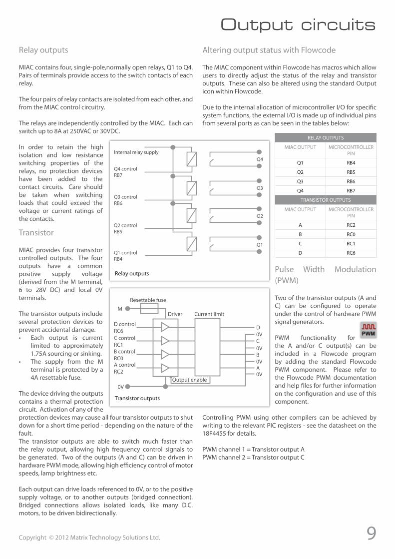
Output circuitsRelay outputs
MIAC contains four, single-pole,normally open relays, Q1 to Q4. Pairs of terminals provide access to the switch contacts of each relay.
The four pairs of relay contacts are isolated from each other, and from the MIAC control circuitry.
The relays are independently controlled by the MIAC. Each can switch up to 8A at 250VAC or 30VDC.
In order to retain the high isolation and low resistance switching properties of the relays, no protection devices have been added to the contact circuits. Care should be taken when switching loads that could exceed the voltage or current ratings of the contacts.
Q4
Q3
Q2
Q1
Internal relay supply
Q4 control RB7
Q3 control RB6
Q2 control RB5
Q1 control RB4
Relay outputs
Transistor
MIAC provides four transistor controlled outputs. The four outputs have a common positive supply voltage (derived from the M terminal, 6 to 28V DC) and local 0V terminals.
The transistor outputs include several protection devices to prevent accidental damage.• Each output is current
limited to approximately 1.75A sourcing or sinking.
• The supply from the M terminal is protected by a 4A resettable fuse.
The device driving the outputs contains a thermal protection circuit. Activation of any of the protection devices may cause all four transistor outputs to shut down for a short time period - depending on the nature of the fault.The transistor outputs are able to switch much faster than the relay output, allowing high frequency control signals to be generated. Two of the outputs (A and C) can be driven in hardware PWM mode, allowing high efficiency control of motor speeds, lamp brightness etc.
Each output can drive loads referenced to 0V, or to the positive supply voltage, or to another outputs (bridged connection). Bridged connections allows isolated loads, like many D.C. motors, to be driven bidirectionally.
D control RC6C control RC1B control RC0A control RC2
M
0V
D0VC0VB0VA0V
Driver Current limit
Output enable
Resettable fuse
Transistor outputs
Altering output status with Flowcode
The MIAC component within Flowcode has macros which allow users to directly adjust the status of the relay and transistor outputs. These can also be altered using the standard Output icon within Flowcode.
Due to the internal allocation of microcontroller I/O for specific system functions, the external I/O is made up of individual pins from several ports as can be seen in the tables below:
RELAY OUTPUTS
MIAC OUTPUT MICROCONTROLLER PIN
Q1 RB4
Q2 RB5
Q3 RB6
Q4 RB7
TRANSISTOR OUTPUTS
MIAC OUTPUT MICROCONTROLLER PIN
A RC2
B RC0
C RC1
D RC6
Pulse Width Modulation (PWM)
Two of the transistor outputs (A and C) can be configured to operate under the control of hardware PWM signal generators.
PWM functionality for the A and/or C output(s) can be included in a Flowcode program by adding the standard Flowcode PWM component. Please refer to the Flowcode PWM documentation and help files for further information on the configuration and use of this component.
Controlling PWM using other compilers can be achieved by writing to the relevant PIC registers - see the datasheet on the 18F4455 for details.
PWM channel 1 = Transistor output APWM channel 2 = Transistor output C
10 Copyright © 2012 Matrix Technology Solutions Ltd.
Operator interfaceThe operator interface consists of:• A status LED for each input.• A status LED for each output.• An indicator LED for the power supply.• An indicator LED for the USB port.• A 16 x 4 character LCD.• A 9-key keypad.
LED indicators
The input and output LEDs indicate the logic level present on their associated terminals. An input LEDs state is not valued when its input is being read as an analogue value. A LED could be weakly lit and yet not at a ‘high’ level. The need for the LED to indicate analogue voltage dictates this.
The POWER LED is driven by the internal logic supply and indicates that both the power and logic supplies are present. The USB LED is illuminated when a USB connection is present, and will flash to indicate activity on the USB port.
Keypad
The keypad consists of 9 keys. None of the keys have any specific software functions assigned to them, but are physically arranged to represent a range of frequently used operations:• 4 cursor control/navigation buttons arranged in a circle.• An OK (enter/select) button in the middle of the cursor keys.• 4 function keys, individually coloured for ease of
identification and referencing from the LCD.• 2 of the function keys have been allocated useful icons
(MENU and Go Back/Undo).• 2 of the function keys are coloured red and green to
represent STOP & START or ON & OFF controls. These are assigned the icons ‘F1’ and ‘F2’ implying Function 1 and Function 2.
Using the keypad in Flowcode
KEY ICON VALUE
Cursor centre OK 4
Cursor up 5
Cursor down 3
Cursor left 1
Cursor right 7
Green Menu 8
Red Undo 6
Yellow F1 2
Blue F2 0
Key values returned by GetKeypad function
Within Flowcode the MIAC component includes macros for returning the number of the key pressed (see table). The user program can freely define the functions allocated to each key, and the way the keypad interacts with the LCD.
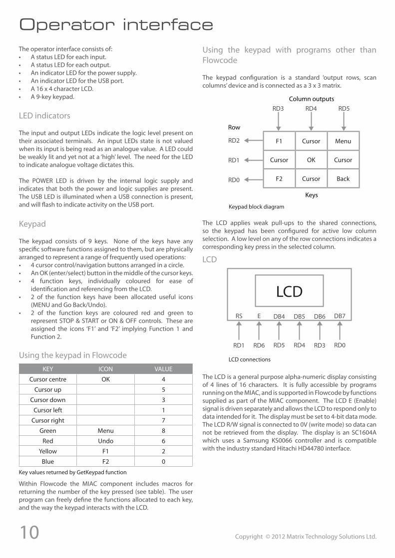
Using the keypad with programs other than Flowcode
The keypad configuration is a standard ‘output rows, scan columns’ device and is connected as a 3 x 3 matrix.
F1 Cursor Menu
Cursor OK Cursor
F2 Cursor Back
Column outputs
Keys
Row
RD3 RD4 RD5
RD2
RD1
RD0
Keypad block diagram
The LCD applies weak pull-ups to the shared connections, so the keypad has been configured for active low column selection. A low level on any of the row connections indicates a corresponding key press in the selected column.
LCDRS E DB4 DB5 DB6 DB7
RD1 RD6 RD5 RD4 RD3 RD0
LCD
LCD connections
The LCD is a general purpose alpha-numeric display consisting of 4 lines of 16 characters. It is fully accessible by programs running on the MIAC, and is supported in Flowcode by functions supplied as part of the MIAC component. The LCD E (Enable) signal is driven separately and allows the LCD to respond only to data intended for it. The display must be set to 4-bit data mode. The LCD R/W signal is connected to 0V (write mode) so data can not be retrieved from the display. The display is an SC1604A which uses a Samsung KS0066 controller and is compatible with the industry standard Hitachi HD44780 interface.

11Copyright © 2012 Matrix Technology Solutions Ltd.
CAN (Control Area Network) is a standard serial communications bus used widely in both automotive and industrial applications. This bus can be used to network multiple MIAC units, and to communicate with other CAN equipped devices.
Each MIAC contains all the hardware necessary to operate as a CAN node. Successful transmission at high speed, and over long distances, requires good wiring practices to be observed:
• Suitable twisted pair cable should be used.• Branches to individual nodes must be kept as short as
possible so the CAN bus has definite start and end nodes.• Terminating resistors should be fitted at the start and end
of the bus.
Each MIAC contains an internal terminating resistor that can be included in the CAN bus connections by adding a link between the TA and TB terminals.
CAN software functionality is included in a MIAC flowchart by adding the standard Flowcode CAN components:
Please refer to the Flowcode CAN documentation and help files for further information on the configuration and use of this component.
CAN offers the advantages of fast data transfer, long transmission lengths, high immunity from electrical noise, and the ability to support multiple devices sharing the same connections - making networks relatively simple to create.
CAN bus interface
MIAC MIAC
HL
TA
TB
MIAC
CAN equipped
device
HL
TA
TB
Example CAN bus wiring showing termination
CAN bus wiring
The CAN bus is controlled by an MCP2515 CAN controller chip. The PIC communicates with it via its SPI peripheral hardware using the pins shown in the diagram. The output from the MCP2515 is fed into a CAN line driver chip and then fed to
the CAN-H and CAN-L lines on the MIAC. Microchip provide plenty of information on driving the CAN bus in the MCP2515 datasheet if a development tool other than Flowcode is to used.
/INT
/CS
SO
SI
SCK
MCP2515PIC
RA4
RD7
RB0/SDI
RC7/SDO
RB1/SCK
CANdriver
Internal CAN bus controller chip connection
Using CAN within a ‘MIAC System’
Users may encounter difficulties when using CAN within a MIAC system, as the MIAC system uses the protocol to control the expansion modules.
Advanced users who wish to use CAN within a MIAC system should refer to the published CAN protocol documentation for the MIAC system.
Also notes that the CAN components within Flowcode are not available for use within a MIAC system. Instead the user will need to access the C-code functions directly via a C icon within the flowchart.
12 Copyright © 2012 Matrix Technology Solutions Ltd.
Using the MIAC systemMIAC systems are based on a principal of starting off with one ‘Master’ MIAC and then adding to the project other peripherals, such as additional ‘Slave’ MIACs or one or more of the available MIAC expansion modules.
The MIAC system is programmed primarily in Flowcode, it is possible to program in C or ASM but this would be for very advanced users only.
MIAC system devices
‘Master’MIACThe ‘Master’ MIAC is the main piece of equipment in a MIAC system, it is the device which will be programmed within Flowcode. Currently only one ‘Master’ MIAC can be present in the system.
‘Slave’MIACThe ‘Slave’ MIAC is a MIAC device which has been programmed with a specific ‘Slave’ program, this allows the ‘Master’ device to control the slave. Up to four slave MIACs can be connected to a MIAC system. More information on setting up a MIAC slave will be detailed later in the document. There will be a visible difference in the components when ‘Slave’ MIACs are added into a Flowcode project.
MIACexpansionmodulesThere are a number of MIAC expansion modules that are available to add to a MIAC system, each of these are detailed later on in this document. Up to four of each individual modules can be connected to any one MIAC system. E.g. Four Basic and two Bluetooth modules could be connected to one system but not five Basic modules.
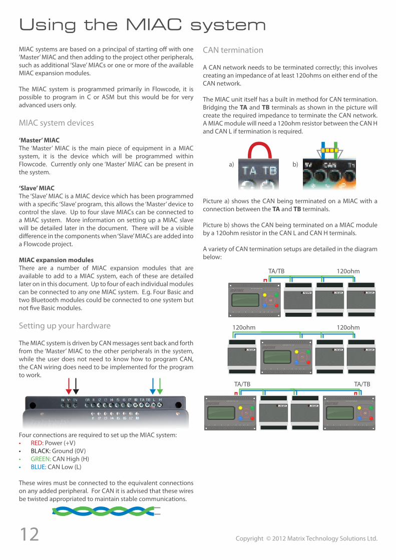
Setting up your hardware
The MIAC system is driven by CAN messages sent back and forth from the ‘Master’ MIAC to the other peripherals in the system, while the user does not need to know how to program CAN, the CAN wiring does need to be implemented for the program to work.
Four connections are required to set up the MIAC system:• RED: Power (+V)• BLACK: Ground (0V)• GREEN: CAN High (H)• BLUE: CAN Low (L)
These wires must be connected to the equivalent connections on any added peripheral. For CAN it is advised that these wires be twisted appropriated to maintain stable communications.
CAN termination
A CAN network needs to be terminated correctly; this involves creating an impedance of at least 120ohms on either end of the CAN network.
The MIAC unit itself has a built in method for CAN termination. Bridging the TA and TB terminals as shown in the picture will create the required impedance to terminate the CAN network. A MIAC module will need a 120ohm resistor between the CAN H and CAN L if termination is required.
a) b)
Picture a) shows the CAN being terminated on a MIAC with a connection between the TA and TB terminals.
Picture b) shows the CAN being terminated on a MIAC module by a 120ohm resistor in the CAN L and CAN H terminals.
A variety of CAN termination setups are detailed in the diagram below:
TA/TB 120ohm
120ohm 120ohm
TA/TB TA/TB
13Copyright © 2012 Matrix Technology Solutions Ltd.
Using the MIAC systemSetting up your MIAC slave devices
A MIAC ‘slave’ device can be created by using a normal MIAC and programming it with the ‘slave’ MIAC program which is available on our website.
Once the ‘slave’ MIAC program (bundled as a hex file) has been downloaded, it will need to be loaded in to the MIAC which is to be the ‘slave’ device. To do this the MIAC programming tool will be required, this tool is installed as part of the Flowcode package (in the Tools folder of the Flowcode installation) or available as a download on our website. The programming tool is called MIACprog.exe.
Using MIACprog the ‘slave’ hex file can be sent to the MIAC therefore turning it into a ‘slave’ device. For more information on sending files via MIACprog, please refer to the MIACprog help file.
Selecting a module ID on a ‘slave’
Once the MIAC program has been programmed the ID of the slave module will need to be selected. This is done so that the ‘master’ MIAC recognises the device and sends data to the correct ‘slave’.
To set the module ID of the ‘slave’ device:• Power down the MIAC• Hold in the green button (pictured)• Power on the MIAC• Use the left and right menu buttons to select an ID for the
‘slave’ device.
The slave ID is persisted in internal EEPROM, so only needs setting once. Keep a note of which ‘slave’ device is which, especially when using multiple slaves.
Module ID jumper select
In any one MIAC system, up to four of each type of MIAC module can be used; for the system to differentiate between multiple modules, they each need to be assigned an ‘ID’. The module ID is an identifier for Flowcode, this is explained further later in the document.
Note that following these instructions should only be done when there is more than one of each module in a MIACsystem. E.g. In the system below the second Bluetooth module
would need to have its module ID changed.
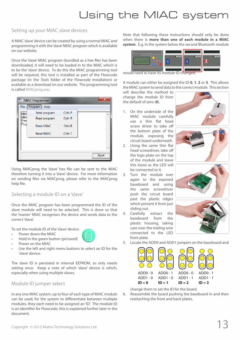
A module can either be assigned the ID 0, 1, 2 or 3. This allows the MIAC system to send data to the correct module. This section will describe the method to change the module ID from the default of zero (0).
1. On the underside of the MIAC module carefully use a thin flat head screw driver to take off the bottom plate of the module, exposing the circuit board underneath.
2. Using the same thin flat head screwdriver, take off the logo plate on the top of the module and leave this loose as the LED will be connected to it.
3. Turn the module over again to the exposed baseboard and using the same screwdriver push the circuit board past the plastic ridges which prevent it from just sliding out.
4. Carefully extract the baseboard from the plastic housing, taking care over the trailing wire connected to the LED front plate.
5. Locate the ADD0 and ADD1 jumpers on the baseboard and
change them to set the ID for the board.6. Reassemble the board pushing the baseboard in and then
reattaching the front and back plates.
ADD0 - 0ADD1 - 0ID=0
ADD0 - 1ADD1 - 0ID=1
ADD0 - 0ADD1 - 1ID=2
ADD0 - 1ADD1 - 1ID=3
14 Copyright © 2012 Matrix Technology Solutions Ltd.
The MIAC system modulesIntroduction to the MIAC system expansion modules
The MIAC expansion modules are powered via a nominally 12 volt DC supply to the 12V and 0V terminals. The power supply is filtered internally and also provides a 5V output terminal for supplying external circuitry such as level shifting components.
All interface terminals are TTL level compatible and are internally protected against over voltage input and have a current limited output. Many are multipurpose, also providing analogue inputs and serial interface features. For further details please see the Interface Protection and individual module Block Schematic sections of this manual.
Central to the MIAC expansion module is a Microchip dsPIC30F5013 high-performance, 16-bit digital signal controller, which is not directly programmable by the user, but instead receives its instructions via the CAN bus from a controlling master MIAC as part of a MIAC system.
For a software perspective, individual terminals of the MIAC expansion modules can be read as input or driven as output. More complex interface protocols and features are also handled within the MIAC expansion module itself, simplifying the application development whilst giving the user flexibility and control.
The features of the MIAC expansion modules can be easily and simply used by dragging and dropping the relevant component as part of a Flowcode project that targets the master MIAC of a MIAC system.
Adding in a battery
Both the Advanced and the GPS module can have a battery inside them to improve communications. Having a cell battery inside the GPS module for example will allow the device to synchronise faster with the satellites from a cold boot. The Advanced module has a battery backup to provide power to the RTC (Real Time Clock) when the module is not powered up.
Below is a picture of the location of the cell battery holder within the device, to open up
the module, please follow the instructions on page 13/14.
The required cell battery is a CR-2032 coin cell.
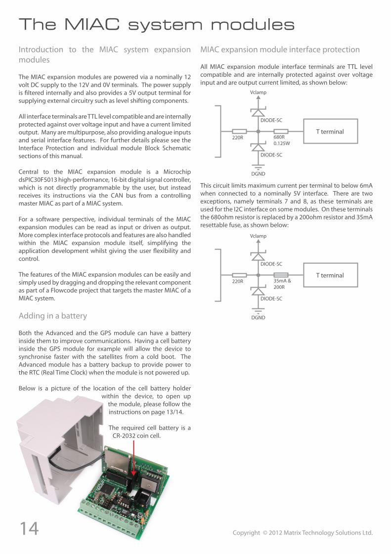
MIAC expansion module interface protection
All MIAC expansion module interface terminals are TTL level compatible and are internally protected against over voltage input and are output current limited, as shown below:
T terminal220R 680R
0.125W
DIODE-SC
DIODE-SC
Vclamp
DGND
This circuit limits maximum current per terminal to below 6mA when connected to a nominally 5V interface. There are two exceptions, namely terminals 7 and 8, as these terminals are used for the I2C interface on some modules. On these terminals the 680ohm resistor is replaced by a 200ohm resistor and 35mA resettable fuse, as shown below:
T terminal220R 35mA &
200R
DIODE-SC
DIODE-SC
Vclamp
DGND
15Copyright © 2012 Matrix Technology Solutions Ltd.
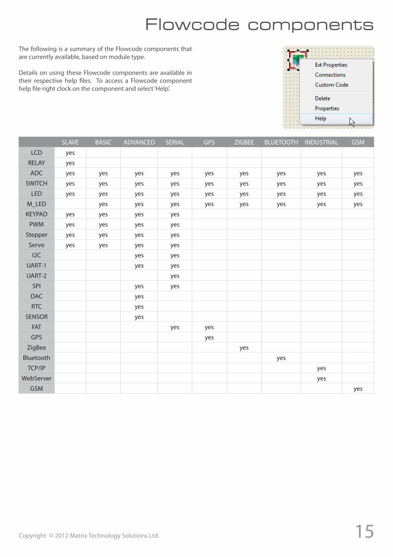
Flowcode componentsThe following is a summary of the Flowcode components that are currently available, based on module type.
Details on using these Flowcode components are available in their respective help files. To access a Flowcode component help file right clock on the component and select ‘Help’.
SLAVE BASIC ADVANCED SERIAL GPS ZIGBEE BLUETOOTH INDUSTRIAL GSM
LCD yes
RELAY yes
ADC yes yes yes yes yes yes yes yes yes
SWITCH yes yes yes yes yes yes yes yes yes
LED yes yes yes yes yes yes yes yes yes
M_LED yes yes yes yes yes yes yes yes
KEYPAD yes yes yes yes
PWM yes yes yes yes
Stepper yes yes yes yes
Servo yes yes yes yes
I2C yes yes
UART-1 yes yes
UART-2 yes
SPI yes yes
DAC yes
RTC yes
SENSOR yes
FAT yes yes
GPS yes
ZigBee yes
Bluetooth yes
TCP/IP yes
WebServer yes
GSM yes
16 Copyright © 2012 Matrix Technology Solutions Ltd.
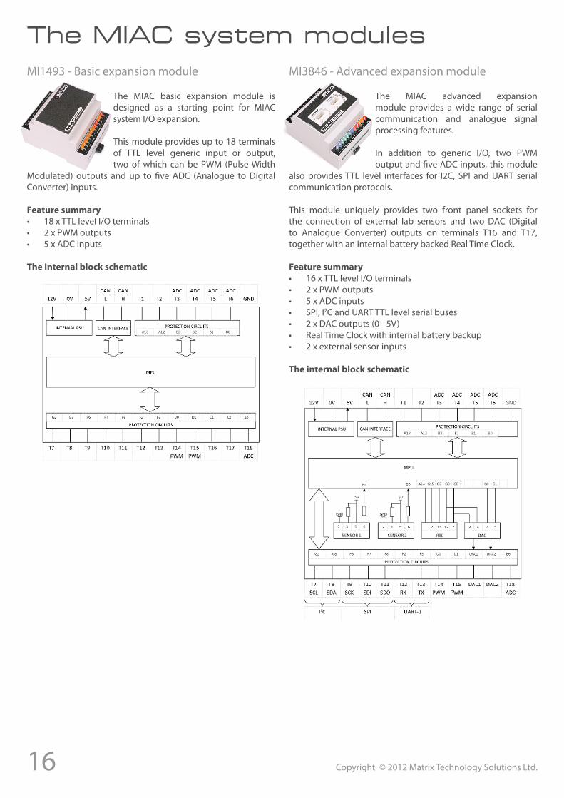
The MIAC system modulesMI1493 - Basic expansion module
The MIAC basic expansion module is designed as a starting point for MIAC system I/O expansion.
This module provides up to 18 terminals of TTL level generic input or output, two of which can be PWM (Pulse Width
Modulated) outputs and up to five ADC (Analogue to Digital Converter) inputs.
Featuresummary• 18 x TTL level I/O terminals• 2 x PWM outputs• 5 x ADC inputs
Theinternalblockschematic
MI3846 - Advanced expansion module
The MIAC advanced expansion module provides a wide range of serial communication and analogue signal processing features.
In addition to generic I/O, two PWM output and five ADC inputs, this module
also provides TTL level interfaces for I2C, SPI and UART serial communication protocols.
This module uniquely provides two front panel sockets for the connection of external lab sensors and two DAC (Digital to Analogue Converter) outputs on terminals T16 and T17, together with an internal battery backed Real Time Clock.
Featuresummary• 16 x TTL level I/O terminals• 2 x PWM outputs• 5 x ADC inputs• SPI, I2C and UART TTL level serial buses• 2 x DAC outputs (0 - 5V)• Real Time Clock with internal battery backup• 2 x external sensor inputs
Theinternalblockschematic
17Copyright © 2012 Matrix Technology Solutions Ltd.
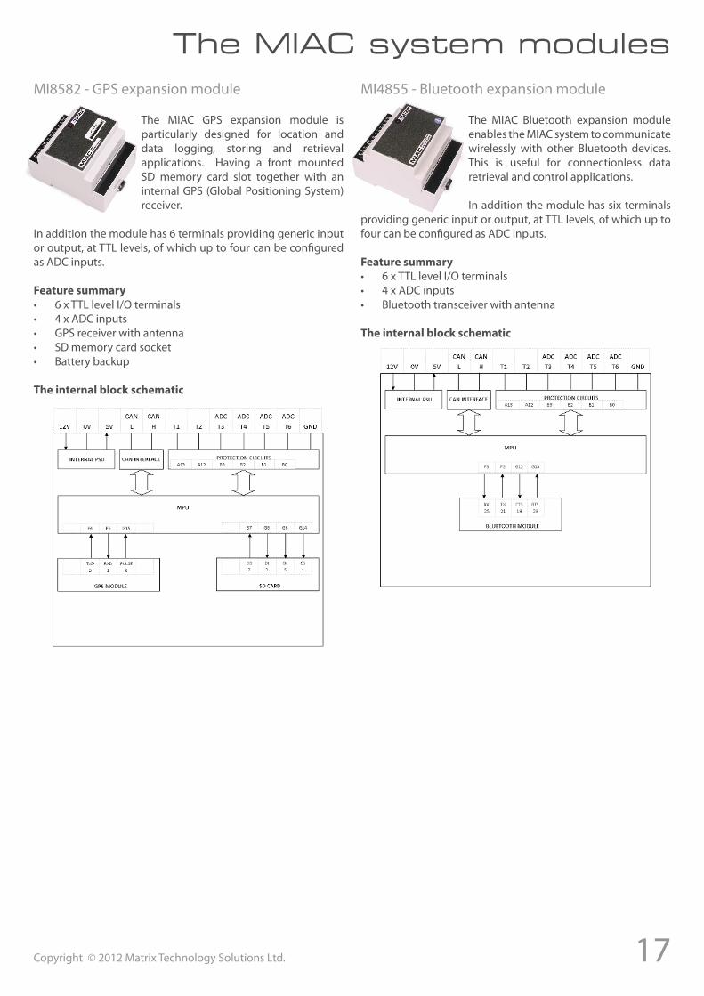
MI8582 - GPS expansion module
The MIAC GPS expansion module is particularly designed for location and data logging, storing and retrieval applications. Having a front mounted SD memory card slot together with an internal GPS (Global Positioning System) receiver.
In addition the module has 6 terminals providing generic input or output, at TTL levels, of which up to four can be configured as ADC inputs.
Featuresummary• 6 x TTL level I/O terminals• 4 x ADC inputs• GPS receiver with antenna• SD memory card socket• Battery backup
Theinternalblockschematic
The MIAC system modulesMI4855 - Bluetooth expansion module
The MIAC Bluetooth expansion module enables the MIAC system to communicate wirelessly with other Bluetooth devices. This is useful for connectionless data retrieval and control applications.
In addition the module has six terminals providing generic input or output, at TTL levels, of which up to four can be configured as ADC inputs.
Featuresummary• 6 x TTL level I/O terminals• 4 x ADC inputs• Bluetooth transceiver with antenna
Theinternalblockschematic
18 Copyright © 2012 Matrix Technology Solutions Ltd.
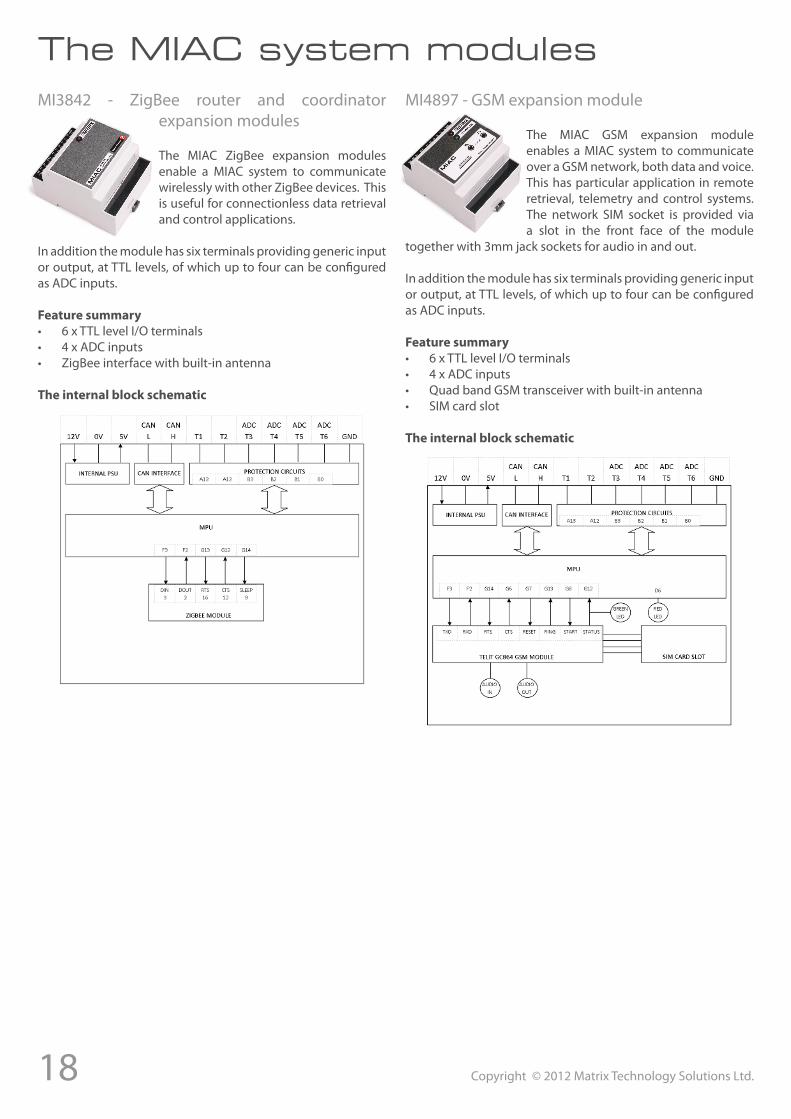
MI3842 - ZigBee router and coordinator expansion modules
The MIAC ZigBee expansion modules enable a MIAC system to communicate wirelessly with other ZigBee devices. This is useful for connectionless data retrieval and control applications.
In addition the module has six terminals providing generic input or output, at TTL levels, of which up to four can be configured as ADC inputs.
Featuresummary• 6 x TTL level I/O terminals• 4 x ADC inputs• ZigBee interface with built-in antenna
Theinternalblockschematic
The MIAC system modulesMI4897 - GSM expansion module
The MIAC GSM expansion module enables a MIAC system to communicate over a GSM network, both data and voice. This has particular application in remote retrieval, telemetry and control systems. The network SIM socket is provided via a slot in the front face of the module
together with 3mm jack sockets for audio in and out.
In addition the module has six terminals providing generic input or output, at TTL levels, of which up to four can be configured as ADC inputs.
Featuresummary• 6 x TTL level I/O terminals• 4 x ADC inputs• Quad band GSM transceiver with built-in antenna• SIM card slot
Theinternalblockschematic
19Copyright © 2012 Matrix Technology Solutions Ltd.
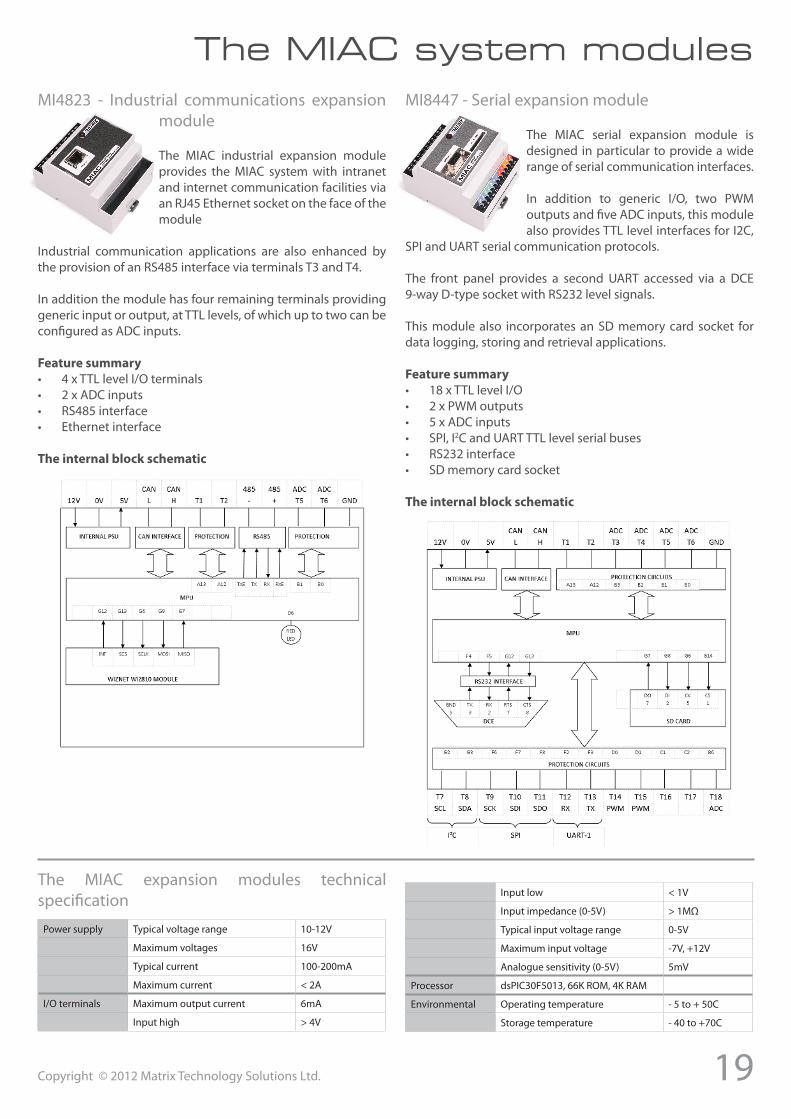
MI4823 - Industrial communications expansion module
The MIAC industrial expansion module provides the MIAC system with intranet and internet communication facilities via an RJ45 Ethernet socket on the face of the module
Industrial communication applications are also enhanced by the provision of an RS485 interface via terminals T3 and T4.
In addition the module has four remaining terminals providing generic input or output, at TTL levels, of which up to two can be configured as ADC inputs.
Featuresummary• 4 x TTL level I/O terminals• 2 x ADC inputs• RS485 interface• Ethernet interface
Theinternalblockschematic
The MIAC system modulesMI8447 - Serial expansion module
The MIAC serial expansion module is designed in particular to provide a wide range of serial communication interfaces.
In addition to generic I/O, two PWM outputs and five ADC inputs, this module also provides TTL level interfaces for I2C,
SPI and UART serial communication protocols.
The front panel provides a second UART accessed via a DCE 9-way D-type socket with RS232 level signals.
This module also incorporates an SD memory card socket for data logging, storing and retrieval applications.
Featuresummary• 18 x TTL level I/O• 2 x PWM outputs• 5 x ADC inputs• SPI, I2C and UART TTL level serial buses• RS232 interface• SD memory card socket
Theinternalblockschematic
The MIAC expansion modules technical specification
Power supply Typical voltage range 10-12V
Maximum voltages 16V
Typical current 100-200mA
Maximum current < 2A
I/O terminals Maximum output current 6mA
Input high > 4V
Input low < 1V
Input impedance (0-5V) > 1MΩ
Typical input voltage range 0-5V
Maximum input voltage -7V, +12V
Analogue sensitivity (0-5V) 5mV
Processor dsPIC30F5013, 66K ROM, 4K RAM
Environmental Operating temperature - 5 to + 50C
Storage temperature - 40 to +70C
20 Copyright © 2012 Matrix Technology Solutions Ltd.
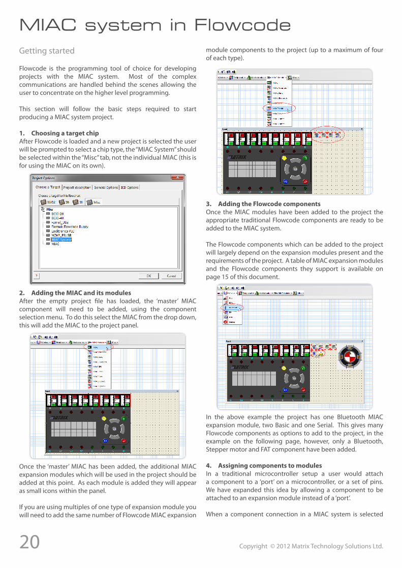
MIAC system in FlowcodeGetting started
Flowcode is the programming tool of choice for developing projects with the MIAC system. Most of the complex communications are handled behind the scenes allowing the user to concentrate on the higher level programming.
This section will follow the basic steps required to start producing a MIAC system project.
1. ChoosingatargetchipAfter Flowcode is loaded and a new project is selected the user will be prompted to select a chip type, the “MIAC System” should be selected within the “Misc” tab, not the individual MIAC (this is for using the MIAC on its own).
2. AddingtheMIACanditsmodulesAfter the empty project file has loaded, the ‘master’ MIAC component will need to be added, using the component selection menu. To do this select the MIAC from the drop down, this will add the MIAC to the project panel.
Once the ‘master’ MIAC has been added, the additional MIAC expansion modules which will be used in the project should be added at this point. As each module is added they will appear as small icons within the panel.
If you are using multiples of one type of expansion module you will need to add the same number of Flowcode MIAC expansion
module components to the project (up to a maximum of four of each type).
3. AddingtheFlowcodecomponentsOnce the MIAC modules have been added to the project the appropriate traditional Flowcode components are ready to be added to the MIAC system.
The Flowcode components which can be added to the project will largely depend on the expansion modules present and the requirements of the project. A table of MIAC expansion modules and the Flowcode components they support is available on page 15 of this document.
In the above example the project has one Bluetooth MIAC expansion module, two Basic and one Serial. This gives many Flowcode components as options to add to the project, in the example on the following page, however, only a Bluetooth, Stepper motor and FAT component have been added.
4. AssigningcomponentstomodulesIn a traditional microcontroller setup a user would attach a component to a ‘port’ on a microcontroller, or a set of pins. We have expanded this idea by allowing a component to be attached to an expansion module instead of a ‘port’.
When a component connection in a MIAC system is selected
21Copyright © 2012 Matrix Technology Solutions Ltd.
instead of the traditional ports being displayed, a list of the available MIAC modules that component can connect to is displayed.
MIAC system in Flowcode
The example in the picture above shows a stepper motor component with an available connection being either MIAC Basic expansion modules or the MIAC Serial expansion module selectable in the ‘Module’ drop down menu.
The ‘Bit’ drop down menu allows the user to select the individual terminals the stepper motor is connected to, these correspond
to the terminals numbered on the MIAC expansion modules themselves. A user will need to remember to attach peripherals to the correct terminals, e.g. if a PWM is required on a basic expansion module, terminals T14 or T15 must be selected in the ‘Bit’ menu.
If more that one module of each type is used, the same number of components need to be added to the system. E.g. If two
Bluetooth expansion modules are attached, then two Bluetooth Flowcode components would need to be added to the project, and connected to the two different expansion modules as described in the method above.
Two MIAC Bluetooth modules with two Bluetooth Flowcode components in the same project.
ImportantnoteonmultipleMIACmodulesandIDs:
If multiple types of one MIAC expansion module are present in the system (up to a maximum of four), the user will have had to change the jumpers within each module to assign it an ID number, these are 0, 1, 2 and 3.
When a MIAC expansion module component is added to the project within Flowcode, it is assigned a sequential ID.
E.g. MIAC_Bluetooth(0) - The underlined zero is the module ID within Flowcode and corresponds to the module ID which needs to be set in hardware via the jumper switch. This should be kept in mind when designing systems with multiple of the same MIAC expansion modules.
5. UsingFlowcodemacrosWhen designing a Flowcode project in a MIAC system, the majority of the interaction will be done with the Flowcode components rather than the expansion module (most only have an LED flasher macro!). This is done in the same way as when creating normal Flowcode programs.
E.g. In the example below the user is interacting with the Bluetooth Flowcode component and using those macros to manipulate the Bluetooth module.
Once the basics of using a MIAC system are understood, the process becomes as easy as using Flowcode under normal circumstances.
There are a few Flowcode courses available for users who wish to learn how to use Flowcode, as well as an extensive help file for Flowcode and each Flowcode component.
More information is available on the matrix website.

22 Copyright © 2012 Matrix Technology Solutions Ltd.
Technical specification
Power supply 12 - 16V DC, < 2A
Inputs 8
Inputs 8 - 0 to 12V DC
Analogue input sensitivity 10mV
Input impedance 10kΩ
Input voltage low 0V - 3V
Input voltage high > 7.5V
Max input voltage range -30V, +45V
Relay outputs 4
Relay output ratings 8A at 240VAC, 30VDC
Transistor outputs (source and sink) 4
Transistor output (per channel) +/- 500mA
Max transistor output - all channels +/- 1.75A
Transistor thermal shutdown > +/- 500mA
PWM outputs, sensitivity 2 (A & C outputs), 0.4%
Power supply 12/16V DC at 100mA
Storage temperature -40 to +70C
Transistor supply voltage (M) 6 - 28V DC, 4A
Operating temperature -5 to 50C
Programming interface USB
Processor PICmicro 18F4455, 12K ROM, 2K RAM @48MHz
CAN bus processor MCP2515 @20MHz
Maximum ratings
Power supply (V+) 16VDC, 2ATransistor output supply (M) 28VDC, 4AInputs (I1 - I8) -30V to +45VTransistor outputs (A,B,C,D) ±1.75A, 0 to 28VDCRelay outputs (Q1 - Q4) 8A @ 240VDC (resistive) 8A @ 30VDC (resistive)Storage temperature -40° to +70°COperating temperature -5°C to +50°CIP rating 20
Warnings
The MIAC unit can operate with hazardous voltages which can result in electric shock or other potentially fatal injuries.• Disconnect all power sources before working on equipment• Do not operate the equipment with case open• Avoid all contact with the connector terminals when any
power sources are connected• Ensure all wiring is in good condition and correctly
terminated
Certification
CE certification:EN 60950-1: 2001+A11:2004EN 55022: 2006 Class BEN 55024: 1998+A1: 2001+A2: 2003
FCC certification:ANSI C63.4 (2003)CISPR 22: 1997+A1: 2000ICES-003: 2004

Matrix Technology Solutions Ltd.33 Gibbet Street
HalifaxHX1 5BA
t: +44 (0)1422 252380e: [email protected]
www.matrixtsl.com


![TOPN Messages - Cisco · %TR-2-PANICINF: Unit [dec], PI [hex] [hex] [hex] [hex] [hex] [hex] Explanation This message is similar to the (Jeanine check source.) Recommended Action Copy](https://static.documents.pub/doc/80x56/5f96ea0c176ab92a087a6e14/topn-messages-cisco-tr-2-panicinf-unit-dec-pi-hex-hex-hex-hex-hex.jpg)


![Sogo Active [Name], [Title] [Name2], [Title2] [Organization]](https://static.documents.pub/doc/80x56/56649ec55503460f94bcf6e7/sogo-active-name-title-name2-title2-organization.jpg)


