36
OPERATING MANUAL INSULATION RESISTANCE METER MIC-30 SONEL Test & Measurement, Inc. Santa Clara, Ca. USA SONEL SA Świdnica, Poland Version 1.1 22/03/2017
| Date post: | 30-Sep-2018 |
| Category: |
Documents |
| Upload: | duongnguyet |
| View: | 218 times |
| Download: | 0 times |

OPERATING MANUAL
INSULATION RESISTANCE METER MIC-30
SONEL Test & Measurement, Inc.
Santa Clara, Ca. USA
SONEL SA Świdnica, Poland
Version 1.1 22/03/2017

OPERATING MANUAL MIC-30 version 1.1 2
Thank you for purchasing the MIC-30 insulation tester.
Please acquaint yourself with this manual to avoid measuring errors and prevent possible problems related to the operation of the meter.
This device complies with part 15 of the FCC Rules. Operation is subject to the following two
conditions: (1) This device may not cause harmful interference, and (2) this device must accept
any interference received, including interference that may cause undesired operation.
This equipment has been tested and found to comply with the limits for a Class A digital device,
pursuant to part 15 of the FCC Rules. These limits are designed to provide reasonable protection
against harmful interference when the equipment is operated in a commercial environment. This
equipment generates, uses, and can radiate radio frequency energy and, if not installed and used
in accordance with the instruction manual, may cause harmful interference to radio
communications. Operation of this equipment in a residential area is likely to cause harmful
interference in which case the user will be required to correct the interference at his own
expense.
This equipment has been tested and found to comply with the limits for a Class B digital device, pursuant to part 15 of the FCC Rules. These limits are designed to provide reasonable protection against harmful interference in a residential installation. This equipment generates, uses and can radiate radio frequency energy and, if not installed and used in accordance with the instructions, may cause harmful interference to radio communications. However, there is no guarantee that interference will not occur in a particular installation. If this equipment does cause harmful interference to radio or television reception, which can be determined by turning the equipment off and on, the user is encouraged to try to correct the interference by one or more of the following measures: - Reorient or relocate the receiving antenna. - Increase the separation between the equipment and receiver. - Connect the equipment into an outlet on a circuit different from that to which the receiver is connected. - Consult the dealer or an experienced radio/TV technician for help.
Responsible for conformity: Sonel Test and Measurement, Inc. 3350 Scott Blvd, Bldg 55, Unit 1 Santa Clara, CA 95054 USA www.SonelTest.com [email protected] tel. +1 408 898 2215
CAUTION:
Equipment changes or modifications not expressly approved by SONEL TEST & MEASUREMENT Inc., the party responsible for FCC compliance, could void the user’s authority to operate the equipment, and could create a hazardous condition.

OPERATING MANUAL MIC-30 version 1.1 3
CONTENTS
1 SAFETY .................................................................................................................... 5
2 METER CONFIGURATION .................................................................................. 6
3 MEASUREMENTS .................................................................................................. 7
3.1 MEASUREMENT OF INSULATION RESISTANCE ........................................................... 7 3.1.1 Double-lead measurement (with a shielded lead) .......................................... 7 3.1.2 Three-lead measurement (with a shielded lead) .......................................... 11 3.1.3 Measurements with WS-04 adapter ............................................................. 12
3.2 LOW-VOLTAGE MEASUREMENT OF RESISTANCE ...................................................... 13 3.2.1 Measurement of resistance of protective conductors and equipotential
bonding with 200 mA current ...................................................................... 13 3.2.2 Measurement of resistance .......................................................................... 15 3.2.3 Compensation of test leads resistance ......................................................... 16
3.3 VOLTAGE MEASUREMENT ..................................................................................... 17 3.4 REMEMBERING THE LAST MEASUREMENT RESULT .................................................. 18
4 MEMORY OF MEASUREMENT RESULT DATA .......................................... 19
4.1 STORING THE MEASUREMENT RESULTS IN THE MEMORY ......................................... 19 4.2 VIEWING MEMORY DATA ....................................................................................... 22 4.3 DELETING MEMORY DATA ..................................................................................... 22
4.3.1 Deleting bank data ....................................................................................... 22 4.3.2 Deleting the whole memory ......................................................................... 24
5 WIRELESS DATA TRANSMISSION ................................................................. 25
5.1 COMPUTER CONNECTION ACCESSORIES ................................................................ 25 5.2 DATA TRANSMISSION WITH BLUETOOTH 4.2 MODULE ............................................ 25
6 FIRMWARE UPDATES ....................................................................................... 27
7 POWER SUPPLY OF THE METER ................................................................... 28
7.1 MONITORING OF THE POWER SUPPLY VOLTAGE ..................................................... 28 7.2 REPLACING BATTERY/RECHARGEABLE BATTERIES .................................................. 28 7.3 GENERAL PRINCIPLES REGARDING USING NIMH RECHARGEABLE BATTERIES .......... 29
8 CLEANING AND MAINTENANCE ................................................................... 29
9 STORAGE .............................................................................................................. 29
10 DISMANTLING AND DISPOSAL ...................................................................... 30
11 TECHNICAL SPECIFICATIONS ....................................................................... 30
11.1 BASIC DATA .......................................................................................................... 30 11.2 ADDITIONAL DATA ................................................................................................ 33
11.2.1 Additional uncertainties according to IEC 61557-2 (RISO) .......................... 33

OPERATING MANUAL MIC-30 version 1.1 4
11.2.2 Additional uncertainties according to IEC 61557-4 (RCONT 200mA) ........... 33
12 EQUIPMENT ......................................................................................................... 34
12.1 STANDARD EQUIPMENT ........................................................................................ 34 12.2 OPTIONAL ACCESSORIES ....................................................................................... 34
13 MANUFACTURER ............................................................................................... 35

OPERATING MANUAL MIC-30 version 1.1 5
1 Safety
The MIC-30 meter is designed to determine the safety of electrical wiring by measuring insulation
resistance to ensure adequate protection against electric shock. For correct operation and accurate results observe the following recommendations:
Before operating the meter acquaint yourself thoroughly with this manual. Observe the safety cautions, warnings, and instructions.
Any application that differs from those specified in this manual may result in a damage to the device and constitute a source of danger to the user.
The MIC-30 meter must be operated only by appropriately qualified personnel with relevant certification authorizing them to work on electrical systems. Operating the meter by unauthorised personnel may result in damage to the device and constitute a source of danger to the user.
During measurements of insulation resistance dangerous voltages up to 1 kV occur at the ends of test leads.
Before any measurement of insulation resistance ensure the tested object is not energized and is disconnected from the mains power supply or an AC power source.
Each test concludes with an automatic discharge of voltage on the object. Do not disconnect the test leads from the tested object before the measurement is completed otherwise high voltage remaining on the object due to it’s capacitance will not be discharged creating a risk of electric shock.
Using this manual does not exclude the need to comply with occupational health and safety regulations and with other relevant fire regulations required during the performance of a particular type of work. Before starting work with the meter in special environments, e.g. potential of fire-risk or explosive environment, consult with the person responsible for health and safety.
Do not operate:
A meter which is damaged, completely or partially malfunctioning
A meter with damaged test leads insulation
A meter stored for an excessive period of time in adverse environmental conditions (e.g. excessive humidity). If the meter is transferred from a cool to a warm environment with a high level of relative humidity, wait 30 minutes until the meter is warmed up to the ambient temperature.
A BATT message indicates insufficient voltage of power supply. The batteries must be charged or replaced.
An ErrX message, where X is a number from 1 to 9, indicates incorrect operation of the meter. If after restarting the meter this error message still appears, it indicates that the meter is damaged.
Before measurement choose a correct measurement function and make sure that test leads are connected securely to their respective measuring terminals.
Do not operate a meter with an open or incorrectly closed battery compartment, or power it from other sources not specified in this manual.
Meter inputs are electronically protected against overloads, such as caused by connecting the meter to a live circuit, up to 550V for measurements, and up to 600V for the voltmeter.
Repairs may only be performed by Sonel or an authorized Sonel service center.
Note:
When installing driver software in Windows may result in an "Installation failed" message. Windows 8 and Windows 10 by default block drivers without a digital signature. Disable the driver signature enforcement in Windows.
Note:
Due to continuous development the actual appearance of the display, and some of the functions may slightly differ from the information presented in this operating manual.

OPERATING MANUAL MIC-30 version 1.1 6
2 Meter Configuration
Turn on the meter by pressing the power and SET/SEL buttons simultaneously.
Use the and buttons to select a parameter.
Use the and buttons to change a parameter value. The value or symbol to be changed flashes.
The symbol indicates an active parameter, the - symbol indicates an inactive one.
Folow this diagram to understand how to select and change settings and parameters:
Parameter Auto-OFF
Change PIN Absorption coefficients
Pairs of WS-04 adapter
Beep signalling pressed
push-button
Selection of
power supply source
Software update
Symbol(s) ,
or
Press ENTER to save the selection. The meter then goes into the measurement mode.
or
Press ESC to go the measurement mode without saving changes.

OPERATING MANUAL MIC-30 version 1.1 7
Notes:
- Each change DAR PI <-> Ab1Ab2 will set standard times t1, t2 and t3: - for PI and DAR t1=30s, t2=60s, t3=none, - for Ab1 and Ab2 t1=15s, t2=60s, t3=none. - Description of a firmware update is presented in the chapter 6.
3 Measurements
3.1 Measurement of insulation resistance
WARNING:
Measured object must be de-energized. Do not make measurements on live circuits.
Important Note:
Make sure that the test leads and probes (crocodile clips) do not touch each other during measurements, especially when measuring high resistance. Such contact may cause the flow of surface currents resulting in additional errors in measurement results.
3.1.1 Double-lead measurement (with a shielded lead)
Set the rotary function switch at one of RISO positions. Each position is marked with the measuring voltage.
Press the SET/SEL button to select the three times for calculating the absorption coefficients - t1, t2, t3.
Use the and buttons to change the settings of t1, t2, t3.
Use the and buttons to change the values of t1, t2, t3.
OPERATING MANUAL MIC-30 version 1.1 8
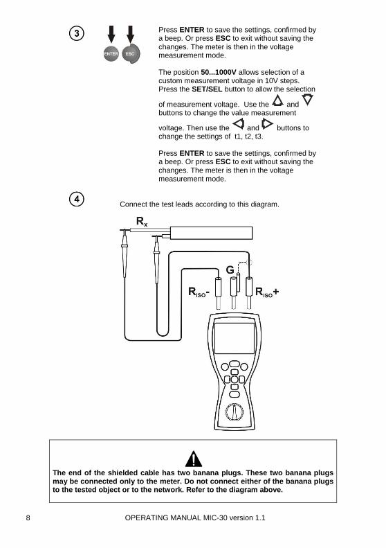
Press ENTER to save the settings, confirmed by a beep. Or press ESC to exit without saving the changes. The meter is then in the voltage measurement mode. The position 50...1000V allows selection of a custom measurement voltage in 10V steps. Press the SET/SEL button to allow the selection
of measurement voltage. Use the and buttons to change the value measurement
voltage. Then use the and buttons to change the settings of t1, t2, t3. Press ENTER to save the settings, confirmed by a beep. Or press ESC to exit without saving the changes. The meter is then in the voltage measurement mode.
Connect the test leads according to this diagram.
The end of the shielded cable has two banana plugs. These two banana plugs may be connected only to the meter. Do not connect either of the banana plugs to the tested object or to the network. Refer to the diagram above.

OPERATING MANUAL MIC-30 version 1.1 9
The meter is ready for measurement.
Press and hold START button. The measurement is performed continuously until the START button is released or the pre-set time is reached.
Instead of holding the START button down continuously, the function can be latched by first pressing the ENTER and then pressing START and releasing both buttons. The
symbol will be displayed. To cancel the measurement press ESC or START.
View of the screen during measurement.
Pressing the SET/SEL button and START simultaneously displays the leakage current IL instead of measurement voltage VISO.
View the results after the measurement is completed.
OPERATING MANUAL MIC-30 version 1.1 10
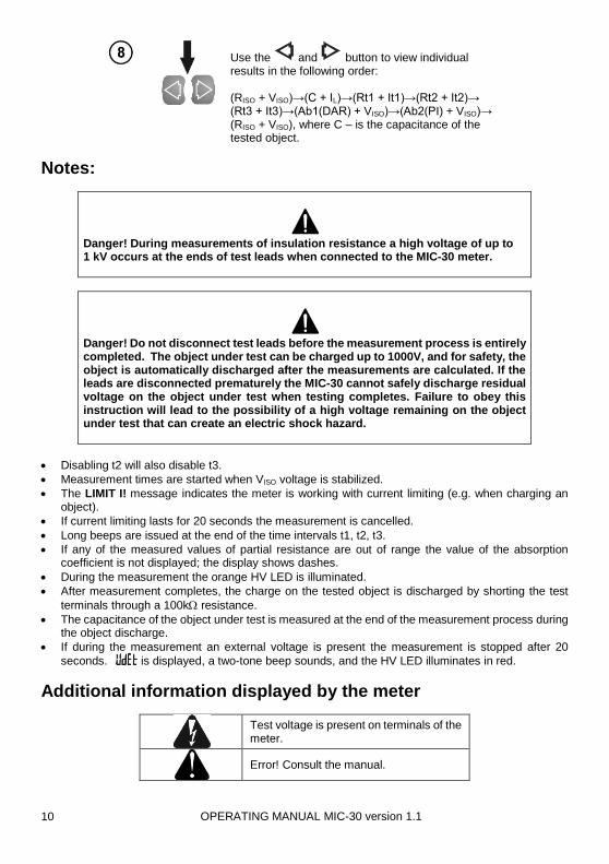
Use the and button to view individual results in the following order: (RISO + VISO)→(C + IL)→(Rt1 + It1)→(Rt2 + It2)→ (Rt3 + It3)→(Ab1(DAR) + VISO)→(Ab2(PI) + VISO)→ (RISO + VISO), where C – is the capacitance of the tested object.
Notes:
Danger! During measurements of insulation resistance a high voltage of up to 1 kV occurs at the ends of test leads when connected to the MIC-30 meter.
Danger! Do not disconnect test leads before the measurement process is entirely completed. The object under test can be charged up to 1000V, and for safety, the object is automatically discharged after the measurements are calculated. If the leads are disconnected prematurely the MIC-30 cannot safely discharge residual voltage on the object under test when testing completes. Failure to obey this instruction will lead to the possibility of a high voltage remaining on the object under test that can create an electric shock hazard.
Disabling t2 will also disable t3.
Measurement times are started when VISO voltage is stabilized.
The LIMIT I! message indicates the meter is working with current limiting (e.g. when charging an object).
If current limiting lasts for 20 seconds the measurement is cancelled.
Long beeps are issued at the end of the time intervals t1, t2, t3.
If any of the measured values of partial resistance are out of range the value of the absorption coefficient is not displayed; the display shows dashes.
During the measurement the orange HV LED is illuminated.
After measurement completes, the charge on the tested object is discharged by shorting the test
terminals through a 100k resistance.
The capacitance of the object under test is measured at the end of the measurement process during the object discharge.
If during the measurement an external voltage is present the measurement is stopped after 20
seconds. is displayed, a two-tone beep sounds, and the HV LED illuminates in red.
Additional information displayed by the meter
Test voltage is present on terminals of the meter.
Error! Consult the manual.

OPERATING MANUAL MIC-30 version 1.1 11
The meter is ready for measurement.
Noise is detected in the system during the measurement. The measurement results may be affected by additional uncertain-ties.
+ continuous audio tone
Current limit is activated.
Leakage current is too high; breakdown of insulation during the measurement.
Object under test is being discharged.
+ red LED, +
two-tone beep
The tested object is live. The measure-ment is cancelled.
Rechargeable batteries are discharged
3.1.2 Three-lead measurement (with a shielded lead)
A three-lead measurement technique is used to eliminate the influence of surface currents. For example, to measure the inter-winding resistance of a small motor, connect the G socket of the meter with the motor housing as in the following diagram:
OPERATING MANUAL MIC-30 version 1.1 12
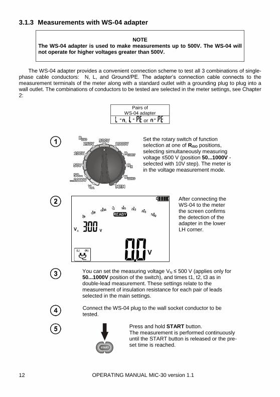
3.1.3 Measurements with WS-04 adapter
NOTE
The WS-04 adapter is used to make measurements up to 500V. The WS-04 will not operate for higher voltages greater than 500V.
The WS-04 adapter provides a convenient connection scheme to test all 3 combinations of single-phase cable conductors: N, L, and Ground/PE. The adapter’s connection cable connects to the measurement terminals of the meter along with a standard outlet with a grounding plug to plug into a wall outlet. The combinations of conductors to be tested are selected in the meter settings, see Chapter 2:
Pairs of WS-04 adapter
, or
Set the rotary switch of function selection at one of RISO positions, selecting simultaneously measuring voltage ≤500 V (position 50...1000V - selected with 10V step). The meter is in the voltage measurement mode.
After connecting the WS-04 to the meter the screen confirms the detection of the adapter in the lower LH corner.
You can set the measuring voltage VN ≤ 500 V (applies only for 50...1000V position of the switch), and times t1, t2, t3 as in double-lead measurement. These settings relate to the measurement of insulation resistance for each pair of leads selected in the main settings.
Connect the WS-04 plug to the wall socket conductor to be tested.
Press and hold START button. The measurement is performed continuously until the START button is released or the pre-set time is reached.

OPERATING MANUAL MIC-30 version 1.1 13
Instead of holding the START button down continuously, the function can be latched by first pressing the ENTER and then pressing START and releasing both buttons. The
symbol will be displayed. To cancel the measurement press ESC or START.
The meter measures the insulation resistance for pairs of conductors in the following order: L-N, L-PE, N-PE.
View the results after the measurement is completed.
Use the and buttons to view the individual results of the measurement for conductor pairs L-N, L-PE, N-PE.
Note:
If the error messages appear: , or LIMIT I! the measurement is cancelled only for the pair of conductors exhibiting the error, and not the other pairs.
If the error message appears, all measurements are cancelled
3.2 Low-voltage measurement of resistance
3.2.1 Measurement of resistance of protective conductors and equipotential bonding with 200 mA current
NOTE
The MIC-30 meter measures RCONT bidirectionally (±200mA).

OPERATING MANUAL MIC-30 version 1.1 14
Set the rotary function switch to the RCONT position.
The meter is ready for measurement.
Connect the meter to the object tested as in the following diagram: The measurement starts automatically when the meter detects a resistance within the measurement range. The measurement may be also triggered manually by pressing the START button.

OPERATING MANUAL MIC-30 version 1.1 15
View the result.
Press the START button to start another measurement without disconnecting the test leads from the object.
Additional information displayed by the meter
Noise is detected in the system during the measurement. The measurement results may be affected by additional uncertaintuies.
+ red LED, + two-
tone beep
The tested object is live. The measurement is cancelled.
Compensation for the test leads resistance is included in the result.
3.2.2 Measurement of resistance
Set the rotary function switch to the RX position.
The meter is ready for measurement.

OPERATING MANUAL MIC-30 version 1.1 16
Connect the meter to the object to be tested as in the following diagram: The measurement is performed continuously.
View the result.
Note:
For R <30Ω there is a continuous beep and the LED illuninates green.
3.2.3 Compensation of test leads resistance
To eliminate the effect of the resistances of the test leads upon the measurements RCONT and RX, perform the auto-zeroing function as follows:
Set the rotary function switch at the RZERO position.

OPERATING MANUAL MIC-30 version 1.1 17
Short the test leads together.
Press START.
and are displayed, confirming the completion of test leads resistance compensation. The compensation for RCONT and RX and is retained in memory for all future meas- urements until auto-zeroing is performed again.
To remove the compensation for test leads resistances, and return to default calibration, perform the auto-zeroing function with the test
leads open. The messages and disappear, and
is displayed.
3.3 Voltage measurement
Set the rotary function switch at the V position.
OPERATING MANUAL MIC-30 version 1.1 18
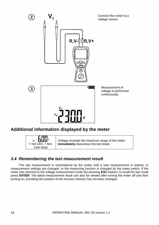
Connect the meter to a voltage source.
Measurement of voltage is performed continuously.
Additional information displayed by the meter
+ red LED, + two-
tone beep
Voltage exceeds the maximum range of the meter. Immediately disconnect the test leads.
3.4 Remembering the last measurement result
The last measurement is remembered by the meter until a new measurement is started, or measurement settings are changed, or the measuring function is changed by the rotary switch. If the meter has returned to the voltage measurement mode (by pressing ESC button), to recall the last result press ENTER. The latest measurement result can also be viewed after turning the meter off and then turning on, providing the position of the function selector has not been changed.

OPERATING MANUAL MIC-30 version 1.1 19
4 Memory of measurement result data
MIC-30 meters are equipped with memory for storing test results. The memory is organized into 10 memory banks with 99 cells in each bank. Each measurement result can be stored in a numbered memory cell in a selected memory bank. Each cell may contain the entire set of measurements of RISO and RCONT. The user can assign memory cell numbers to individual measurement points, and the memory bank numbers to individual facilities, for example. Memory of measurement result data is retained when the meter is switched off. The data can be later viewed again on screen or sent to a computer.
Notes:
Results of measurements performed for all measuring functions can be stored in one memory cell, excluding RX and V .
After entering a measurement result, the cell number is automatically incremented.
It is recommended to save the data to a PC, if important, before performing a new series of measurements to avoid overwriting memory cells and losing needed data.
Optionally, it is recommended to erase the data before performing a new series of measurements to reset the memory to an empty state.
4.1 Storing the measurement results in the memory
After completing measurement press ENTER. The next screen will be one of the following:
Blank spaces indicates the cell is empty.
If the cell has data that corresponds to the data to be stored those results are displayed.

OPERATING MANUAL MIC-30 version 1.1 20
Use the and buttons to preview those results previously stored in the selected cell.
If the cell has data corresponding to a different measure-ment than the one to be entered, a blank rectangle appears.
Use the and buttons to preview those results previously stored in the selected cell.
If the cell is fully occupied a large blank rectangle appears.
Use the and buttons to preview those results previously stored in the selected cell.
To change the cell or bank number use the SET/SEL button to select other cells or banks.
Use the and buttons to change the number of a cell or bank.
OPERATING MANUAL MIC-30 version 1.1 21
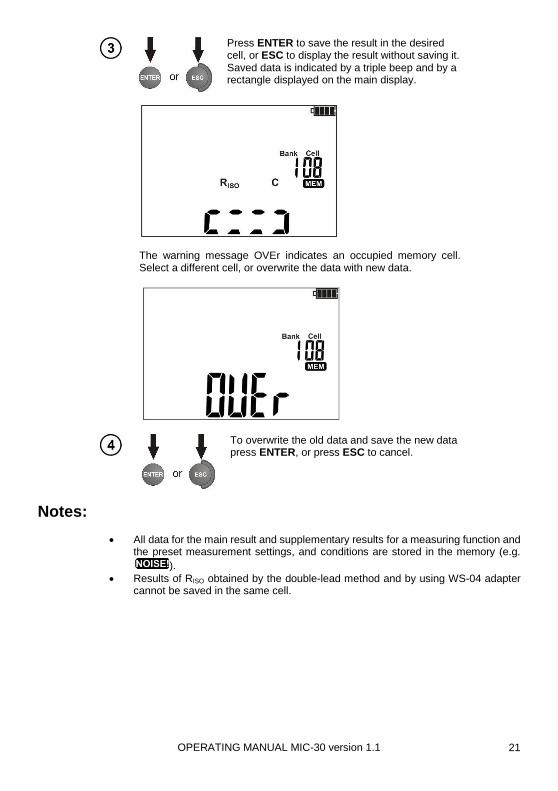
Press ENTER to save the result in the desired cell, or ESC to display the result without saving it. Saved data is indicated by a triple beep and by a rectangle displayed on the main display.
The warning message OVEr indicates an occupied memory cell. Select a different cell, or overwrite the data with new data.
To overwrite the old data and save the new data press ENTER, or press ESC to cancel.
Notes:
All data for the main result and supplementary results for a measuring function and the preset measurement settings, and conditions are stored in the memory (e.g.
).
Results of RISO obtained by the double-lead method and by using WS-04 adapter cannot be saved in the same cell.
OPERATING MANUAL MIC-30 version 1.1 22
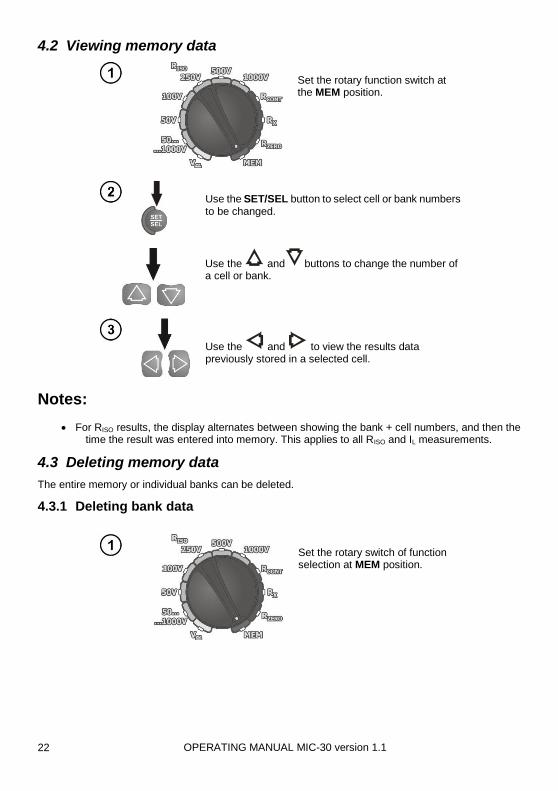
4.2 Viewing memory data
Set the rotary function switch at the MEM position.
Use the SET/SEL button to select cell or bank numbers to be changed.
Use the and buttons to change the number of a cell or bank.
Use the and to view the results data previously stored in a selected cell.
Notes:
For RISO results, the display alternates between showing the bank + cell numbers, and then the time the result was entered into memory. This applies to all RISO and IL measurements.
4.3 Deleting memory data
The entire memory or individual banks can be deleted.
4.3.1 Deleting bank data
Set the rotary switch of function selection at MEM position.

OPERATING MANUAL MIC-30 version 1.1 23
To set the bank number to be deleted toggle the SET/SEL button until the bank number flashes. Use
the andbuttons to change the bank number. Press SET/SEL button until the cell number
flashes. Use the button to change cell number to “--”.
The symbol appears.
Press ENTER.
and appear asking to confirm deletion.
Press ENTER again. After deleting the bank the meter beeps three times and sets the cell number to "01".

OPERATING MANUAL MIC-30 version 1.1 24
4.3.2 Deleting the whole memory
Set the rotary function switch to the MEM position.
Toggle the SET/SEL button until the bank number flashes. Use
the button to change the bank number to “--”.
The symbol appears.
Press ENTER .

OPERATING MANUAL MIC-30 version 1.1 25
and appear asking to confirm deletion.
Press ENTER again. After deleting the memory the meter beeps three times and sets the bank and cell number to "1".
5 Wireless data transmission
5.1 Computer connection accessories
To communicate with a computer the OR-1 wireless module and Sonel Reader PC software is required. It allows users to read and display the measurement data stored in the meter memory. This program may be downloaded free from the manufacturer's website: www.sonel.pl or www.soneltest.com. It is also supplied on a DVD with the meter. The software is compatible with other instruments manufactured by SONEL S.A. equipped with a USB interface and/or wireless module. Detailed information regarding software is available from Sonel or an authorised Sonel distributor.
5.2 Data transmission with Bluetooth 4.2 module
Set the rotary switch of function selection at MEM position.

OPERATING MANUAL MIC-30 version 1.1 26
Press SET/SEL for 2 sec.
The meter displays the screen of wireless communication.
Press ENTER to start the transmission.
Connect Bluetooth module to the USB socket of the PC, unless it is integrated into the PC.
During the process of pairing the meter with a PC enter PIN code compatible with the PIN code of the meter defined in main settings.
On the computer start data storing programme.
Press ESC to exit data transmission mode.
Notes:
Standard pin for Bluetooth is "1234".

OPERATING MANUAL MIC-30 version 1.1 27
6 Firmware updates
In main settings select the update mode option (Chapter 2). The meter displays the following screen.
Press ENTER to start transmission and perform updating according to the instructions of the application.
Connect Bluetooth module to the USB socket of the PC, unless it is integrated into the PC.
During the process of pairing the meter with a PC enter PIN code compatible with the PIN code of the meter defined in main settings.
Run a program for updating the firmware and perform updating according to the instructions of the application.
Notes:
NOTE!
Before updating the firmware insert fully charged batteries or new batteries.
To exit the update mode press ESC, this is possible until the meter starts the process of memory reprogramming - at that time all buttons are inactive.
After the update completes the meter automatically switches off.
Upon switching on the meter briefly displays the current version # of the meter’s firmware.

OPERATING MANUAL MIC-30 version 1.1 28
If the meter displays ErrX (X – error code) turn the meter off and then on. Incomplete updates are deleted and the meter operates on the previous firmware. If another update attempt does not complete successfully the meter should be returned to Sonel for service, or an authorized service center.
7 Power supply of the meter
7.1 Monitoring of the power supply voltage
The level of charge of the batteries is continuously indicated by the battery symbol in the upper right corner of the display:
Batteries charged
Batteries almost discharged.
Batteries are fully discharged. The meter switches off automatically.
7.2 Replacing battery/rechargeable batteries
MIC-30 Meters are powered by four AA alkaline LR6 batteries or NiMH rechargeable batteries.
NOTE! Before removing the battery cover disconnect the test leads.
To replace the batteries: 1. Disconnect the leads from the measuring circuit and turn off the meter 2. Unscrew the 4 screws at the bottom of the housing and remove the cover 3. Replace all batteries with new ones. 4. Replace and fasten the cover.
Note:
Rechargeable batteries must be recharged in an external charger.
NOTE!
Do not use the meter when the battery compartment is removed or open. Do not power the meter from any source other than those described in this manual.

OPERATING MANUAL MIC-30 version 1.1 29
7.3 General principles regarding using NiMH rechargeable batteries
If the meter is not used for a prolonged periods, it is recommended to remove the batteries and store them separately.
Store the rechargeable batteries in a dry, cool, and well-ventilated place and protect them from
direct sunlight. The temperature of the environment should not exceed 30C / 86F. If the rechargeable batteries are stored for a long periods at high temperature their lifetime will be reduced.
NiMH batteries withstand normally 500-1000 charging cycles. NiMH batteries reach their maximum capacity after 2-3 charge/discharge cycles. The most important factor which affects the lifetime of rechargeable batteries is the level of discharge. The deeper the discharge, the shorter the lifetime.
NiMH batteries may be charged at any point with no serious consequences. However, it is recommended to discharge them periodically.
During storage, NiMH batteries self-discharge at the rate of approximately 30% per month. High temperatures accelerate this process. To prevent excessive discharge of rechargeable batteries it is recommended to charge them periodically even if they are not used.
Modern fast chargers detect both too low and too high a temperature of batteries and react accordingly. Too low a temperature prevents charging, which might damage the battery irreparably. High temperature of the battery stops any further charging. Charging at a high temperature reduces battery lifetime and causes a further increase of the battery temperature, which will not allow charging to full capacity.
With quick charging, batteries are charged to approximately 80% of their capacity. Better results may be obtained if charging is continued. Charging will continue, but with a low current. After a couple of hours the batteries are charged to their full capacity.
Do not charge or use batteries in extreme temperatures. Extreme temperatures reduce the lifetime of batteries. Avoid using devices powered from Ni-MH batteries in very hot environments. The nominal working temperature must be observed.
8 Cleaning and maintenance
NOTE!
Only use the maintenance methods described in this manual.
The outside of the MRU-30 meter may be cleaned with a soft, damp cloth using all-purpose detergents. Do not use any solvents or cleaning agents or abrasives which might scratch the case. Clean the probes with water and dry them. Before storing probes for long periods it is recommended to coat it with any machine lubricant to prevent corrosion. Cable reels and test leads should be cleaned with water and detergents and dried. The electronic system of the meter does not require maintenance.
9 Storage
When storing the MRU-30:
Disconnect all the test leads from the meter
Clean the meter and all its accessories thoroughly
Wind the long test leads onto the reels
To prevent a total discharge of the batteries charge them periodically.

OPERATING MANUAL MIC-30 version 1.1 30
10 Dismantling and disposal
Scrap and disused electric and electronic equipment should be disposed of selectively, i.e. not placed with waste of another kind.
Scrap and disused electric and electronic equipment should be sent to a collection point in accordance with local regulations for the disposal of electric and electronic equipment.
Before the equipment is sent to a collection point do not dismantle or disassemble any elements.
Observe local regulations concerning the disposal of equipment, and depleted batteries.
11 Technical specifications
11.1 Basic data
Abbreviation "m.v." used in the specification of measurement uncertainty means a standard measured value.
AC / DC voltage measurement
Display range Resolution Measurement uncertainty
0.0 to 299.9 V 0.1 V (2% m.v. + 6 digits)
300 to 600V 1V (2% m.v. + 2 digits)
Frequency range: 45 to 65Hz Measurement of insulation resistance
Voltage accuracy (Robc [] 1000*VN [V]): -0+10% of the selected value
Measurement range, according to IEC 61557-2 for VN = 50V: 50k to 250.0M
Display range for VN = 50V
Resolution Measurement uncertainty
0.0 to 999.9 k 0.1 k
(3 % m.v. + 8 digits),
[ (5 % m.v. + 8 digits)] *
1.000 to 9.999 M 0.001M
10.00 to 99.99M 0.01 M
100.0 to 250.0 M 0.1 M
* - for WS-04 adapter
Test range according to IEC 61557-2 for VN = 100V: 100k to 500.0M
Display range for VN = 100V
Resolution Measurement uncertainty
0.0 to 999.9 k 0.1 k
(3 % m.v. + 8 digits),
[ (5 % m.v. + 8 digits)] *
1.000 to 9.999 M 0.001M
10.00 to 99.99M 0.01 M
100.0 to 500.0 M 0.1 M
* - for WS-04 adapter

OPERATING MANUAL MIC-30 version 1.1 31
Test range according to IEC 61557-2 for VN = 250V: 250k…2.000G
Display range for VN =250V
Resolution Measurement uncertainty
0.0 to 999.9 k 0.1 k
(3 % m.v. + 8 digits),
[ (5 % m.v. + 8 digits)] *
1.000 to 9.999 M 0.001M
10.00 to 99.99M 0.01 M
100.0 to 999.0 M 0.1 M
1.000 to 2.000 G 0.001 G
* - for WS-04 adapter
Test range according to IEC 61557-2 for VN = 500V: 500k to 20.00G
Display range for VN = 500V
Resolution Basic uncertainty
0.0 to 999.9 k 0.1 k (3 % m.v. + 8 digits),
[ (5 % m.v. + 8 digits)] *
1.000 to 9.999 M 0.001M
10.00 to 99.99M 0.01 M
100.0 to 999.0 M 0.1 M
1.000 to 9.999 G 0.001 G (4 % m.v. + 6 digits)
[ (6 % m.v. + 6 digits)] *
10.00 to 20.00 G 0.01 G
* - for WS-03 lead
Test range according to IEC 61557-2 for VN = 1000V: 1000k to 100.0G
Display range for VN = 1000V
Resolution Basic uncertainty
0.0 to 999.9 k 0.1 k
(3 % m.v. + 8 digits) 1.000 to 9.999 M 0.001M
10.00 to 99.99M 0.01 M
100.0 to 999.9 M 0.1 M
1.000 to 9.999 G 0.001 G
(4 % m.v. + 6 digits) 10.00 to 99.99 G 0.01 G
100.0 G 0.1 G
Note: For insulation resistance below RISOmin there is no accuracy specified because the meter operates in current limit mode in accordance with the following formula:
nomISO
nomISOISO
I
VR min
where: RISOmin - minimum insulation resistance measured without limiting the current VISOnom - nominal test voltage IISOnom - nominal current (1mA) Measurement of leakage current
Display range Resolution Measurement uncertainty
0 to ILmax mA, μA, nA Calculated basing on
resistance measurements
ILmax – maximum current at short circuit of leads,
resolution and units result from the measurement range of individual insulation resistance.

OPERATING MANUAL MIC-30 version 1.1 32
Measurement of capacitance
Display range Resolution Measurement uncertainty
1 to 999nF 1nF (5% m.v. + 10 digits)
1.00 to 9.99μF 0.01μF
Measurement of capacitance is made only during RISO measurement.
For measurement voltages below 100V and when measured resistance is below 10MΩ, the measurement error is not specified.
Low-voltage continuity and resistance measurement Measurement of continuity of protective conductors and equipotential bondings with 200 mA current
Measuring range according to IEC 61557-4: 0.10 to 1999
Display range Resolution Measurement uncertainty
0.00 to 19.99 0.01 (2% m.v. + 3 digits)
20.0 to 199.9 0.1
200 to 1999 1 (4% m.v. + 3 digits)
Voltage at open terminals: <8V
Output current at R < 2: ISC> 200mA
Compensation of test leads resistance
Current flowing bidirectionally, average resistance is displayed
Low-current resistance measurement
Range Resolution Measurement uncertainty
0.0 to 199.9 0.1 (3% m.v. + 3 digits)
200 to 1999 1
Voltage at open terminals: <8V
Current at shorted terminals 5mA< ISC<15mA
Acoustic signal and LED illuminates green for measured resistance < 30 ± 10%
Compensation of test leads resistance Other technical specification a) type of insulation ......................................................double, IEC 61010-1 and IEC 61557 compliant b) measurement category ............................................. IV 600V (III 1000V) according to IEC 61010-1 c) protection class of enclosure acc. to IEC 60529........................................................................ IP67 d) power supply for the meter .................................. 4 AA alkaline batteries or rechargeable batteries e) dimensions ............................................................................ 220 x 100 x 60 mm / 8.7 x 3.9 x 2.4 in f) meter weight ................................................................................................... approx 0.6 kg / 1.3 lb
g) storage temperature ............................................................................ –20 to +70C / –4 to +158F
h) operating temperature .......................................................................... -10 to +50C / 14 to +122F i) humidity ........................................................................................................................... 20 to 90%
j) reference temperature ................................................................................... +23 ± 2C / +73 ± 3F k) reference humidity ........................................................................................................... 40 to 60% l) altitude (above sea level) .................................................................................... <2000 m / <6562 ft m) display ........................................................................................................................ LCD segment n) memory of measurement results ........................................................................................ 990 cells o) data transmission ......................................................................................................... wireless link p) quality standard ........................... development, design and manufacturing are ISO 9001 compliant q) the device meets the requirements of the IEC 61557 standard r) the product meets the EMC requirements (immunity for industrial environment) according to the
following standards ..........................................................................................................................

OPERATING MANUAL MIC-30 version 1.1 33
.................................................................................... IEC 61326-1:2006 and IEC 61326-2-2:2006
11.2 Additional data
Data on additional uncertainties are useful mainly when the meter is used in non-standard conditions and for metrological laboratories for the purpose of calibration.
11.2.1 Additional uncertainties according to IEC 61557-2 (RISO)
Significant parameter Designation Additional uncertainty
Position E1 0%
Supply voltage E2 0% (BATT is not lit)
Temperature 0 to 35°C / 32 to 95°F
E3 2%
11.2.2 Additional uncertainties according to IEC 61557-4 (RCONT 200mA)
Significant parameter Designation Additional uncertainty
Position E1 0%
Supply voltage E2 0% (BATT is not lit)
Temperature 0 to 35°C / 32 to 95°F
E3 2%

OPERATING MANUAL MIC-30 version 1.1 34
12 Equipment
12.1 Standard equipment
Standard set of MIC-30 equipment supplied by the manufacturer includes:
MIC-30 – WMPLMIC30,
1.2 m / 3.2 ft cable CAT III 1000V – 2 pcs (red - WAPRZ1X2REBB, blue - WAPRZ1X2BUBB),
1.2 m / 3.2 ft shielded cable CAT III 1000V – 1 pc - WAPRZ1X2BLBBE,
crocodile clip CAT III 1000V – 1 pc (blue - WAKROBU20K02),
blade probe CAT III 1000V – 2 pcs (black - WASONBLOGB1, red - WASONREOGB1),
wireless module OR-1 - WAADAUSBOR1,
M-6 carrying case for the meter and accessories – WAFUTM6,
calibration certificate,
warranty card,
operating manual,
DVD with software,
Set of 4xAA alkaline batteries 1.5 V,
strap for carrying the meter – WAPOZSZE4,
plastic hook (to hang the meter) – WAPOZUCH1.
12.2 Optional accessories
The following items can be purchased from Sonel or an authorized Sonel distributor:
WAPRZ005REBB WAPRZ005BUBB
5m/16ft cable CAT III 1000V red and blue
WAKRORE20K02
crocodile clip CAT III 1000V red
WAPRZ005BLBBE
5m/16ft shielded cable CAT III 1000V black
WAKROBL20K01
crocodile clip CAT III 1000V black

OPERATING MANUAL MIC-30 version 1.1 35
WASONBUOGB1
test prod with banana socket - blue WAPROSONPE4
SONEL Electrical measurements software for measurement reports
WAADAWS04
WS-04 adapter LSWPLMIC30
calibration certificate
Note
The software is supported by the following operating systems: Windows XP (Service Pack 2), Windows Vista and Windows 7, Windows 8 and Windows 10.
13 Manufacturer
Contact the manufacturer for warranty and post-warranty service:
SONEL Test & Measurement, Inc.
Santa Clara, Ca 95054 USA tel. +1 (408) 898 2215 fax +1 (408) 988 4869 E-mail: [email protected]
Web: www.soneltest.com
SONEL S. A.
58-100 Świdnica Poland tel. +48 74 858 38 60 fax +48 74 858 38 09 E-mail: [email protected]
Web page: www.sonel.pl

OPERATING MANUAL MIC-30 version 1.1 36
Attention:
Service and repairs must be performed only by Sonel or an authorized Sonel service center.


