43
m.apollonio CM18, RAL, 14/6/2007 1 MICE beam diffuser M. Apollonio , J. Cobb, P. Lau, W. Lau, J. Tacon, H. Witte, S. Yang - Univ. Oxford
m.apollonio CM18, RAL, 14/6/2007 1
MICE beam diffuser
M. Apollonio , J. Cobb, P. Lau, W. Lau,
J. Tacon, H. Witte, S. Yang - Univ. Oxford
m.apollonio CM18, RAL, 14/6/2007 2
outline A bit of history …
Choice of radius Choice of thickness
Mechanics Control
Conclusion/Plans
m.apollonio CM18, RAL, 14/6/2007 3
0. Z=-6010 mm for the downstream face of the diffuser. (CR, CM14 Osaka - 2006)
1. radial size R as big as possible
2. thickness limited number of discs to fulfil MICE configurations
3. mechanics & control design still evolving a) new carousel wheel b) motors c) ideas for control (logic)

m.apollonio CM18, RAL, 14/6/2007 4
radial size
m.apollonio CM18, RAL, 14/6/2007 5
LEADING IDEA
trying to exploit all the radial space (15 cm) within the envelope
being compatible with mechanical constraints

m.apollonio CM18, RAL, 14/6/2007 6
7mm 15.5cm
Emi inflation in single layer lead diffuser: 2.8 6.1 mm rad
7mm
emi(after diff)=6 mm rad
Muons selected on the overall channelideal disc

m.apollonio CM18, RAL, 14/6/2007 7
7mm
7mm
5cm 15.5cm
Emi inflation with a single layerof lead (small radius): 2.8 5.3 mm rad
7mm
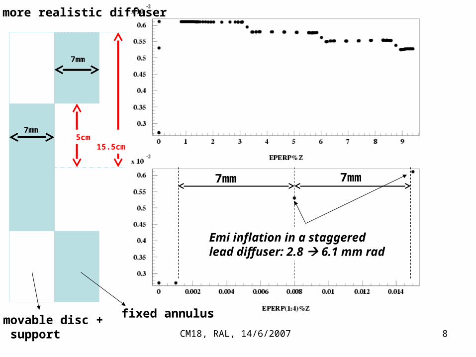
m.apollonio CM18, RAL, 14/6/2007 8
7mm
7mm
5cm 15.5cm
Emi inflation in a staggered lead diffuser: 2.8 6.1 mm rad
7mm 7mm
a more realistic diffuser
fixed annulusmovable disc + support
m.apollonio CM18, RAL, 14/6/2007 9
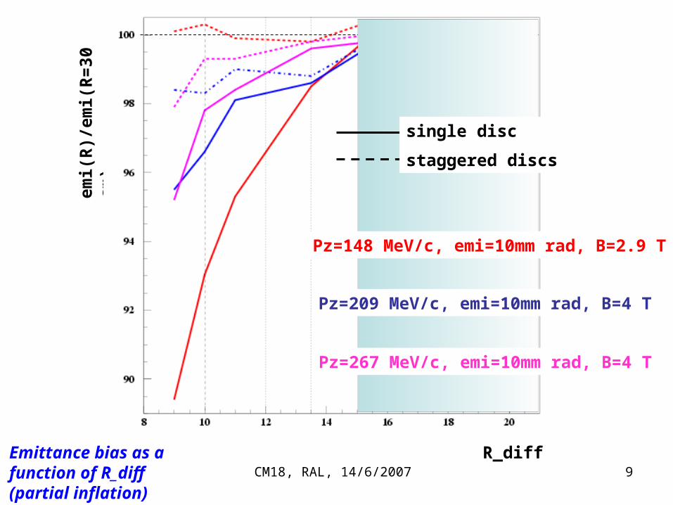
emi(
R)/
emi(
R=
30
cm)
R_diffEmittance bias as a function of R_diff (partial inflation)
Pz=209 MeV/c, emi=10mm rad, B=4 T
Pz=148 MeV/c, emi=10mm rad, B=2.9 T
Pz=267 MeV/c, emi=10mm rad, B=4 T
single disc
staggered discs

m.apollonio CM18, RAL, 14/6/2007 1010 mm
Proposal to accommodate many configurations STAGGERED/TAPERED with a fixed external annulus …just a sketch (see Peter/Joseph/Stephanie drawings)
24 t
o 2
7 c
m
30 c
m
trackerdiffuser
envelope
Supports (outer can/disc support): Al
Pb diffuser disc and outer annulus
1.5 to 15.5 mm

m.apollonio CM18, RAL, 14/6/2007 11
thickness choice
m.apollonio CM18, RAL, 14/6/2007 12
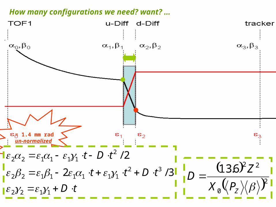
= 1.4 mm radun-normalized
How many configurations we need? want? …
tD
tDtt
tDt
1122
3211111122
2111122
3/2
2/
20
226.13
ZPX
ZD

m.apollonio CM18, RAL, 14/6/2007 13
… maybe 5 discs are enough (at least to begin with)Thinner disc: Pb Steel?
MICE note in preparation
m.apollonio CM18, RAL, 14/6/2007 14
mechanics

m.apollonio CM18, RAL, 14/6/2007 15
automatic device with 3 main movements & accurate positioning
Carousel (revolving) Discs (+/- 15 deg) Catcher (linear motion through a threaded
cylinder)
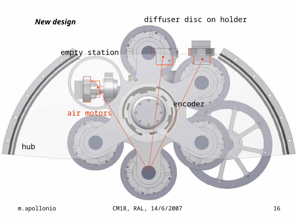
m.apollonio CM18, RAL, 14/6/2007 16
New design
hub
air motors
empty station
diffuser disc on holder
encoder
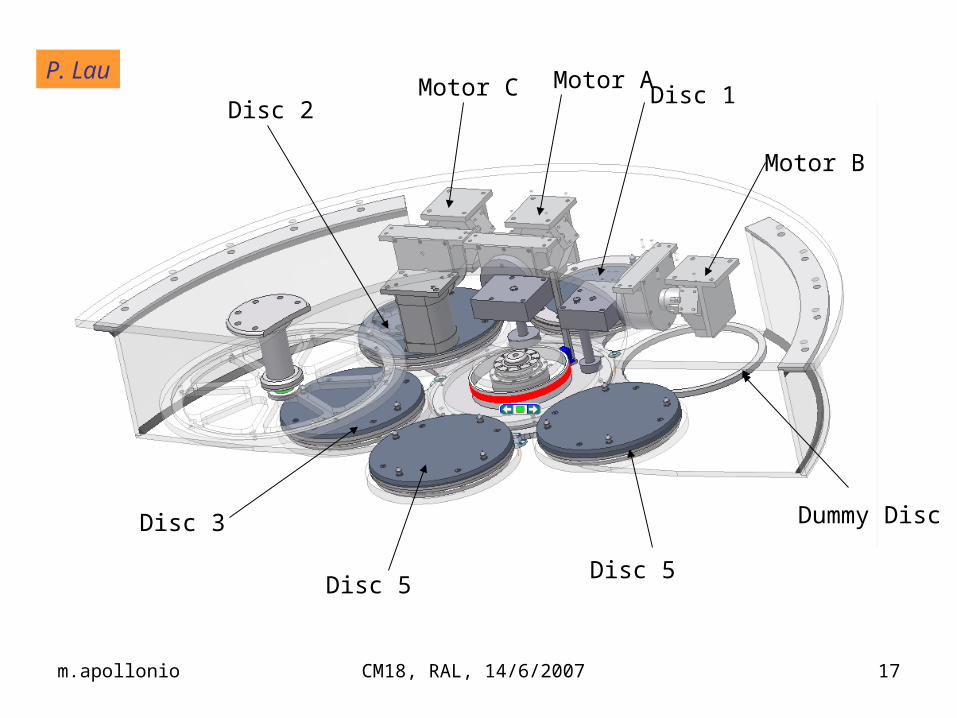
m.apollonio CM18, RAL, 14/6/2007 17
Disc 2Disc 1
Dummy Disc
Disc 5
Disc 3
Disc 5
Motor A
Motor B
Motor CP. Lau
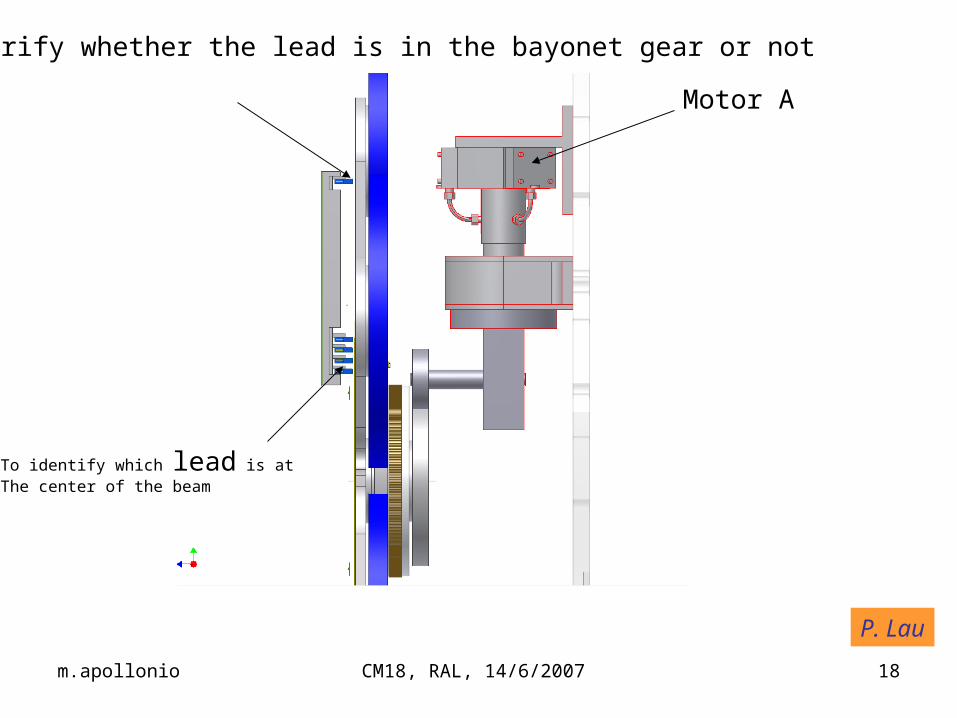
m.apollonio CM18, RAL, 14/6/2007 18
To verify whether the lead is in the bayonet gear or not
To identify which lead is atThe center of the beam
Motor A
P. Lau

m.apollonio CM18, RAL, 14/6/2007 19
Motor B to drive to turnthe disc holder 15° clockwise& anti-clockwise
Encoder
Encoder Reader
Bayonet Gear;Turn 15° to clockwise to unlock and anti-Clockwise to lock
P. Lau

m.apollonio CM18, RAL, 14/6/2007 20
This gear is to drive the diffuser catcher forward and backward
Motor CP. Lau
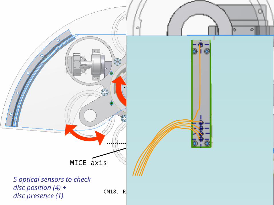
m.apollonio CM18, RAL, 14/6/2007 21
5 optical sensors to check disc position (4) +disc presence (1)
MICE axis
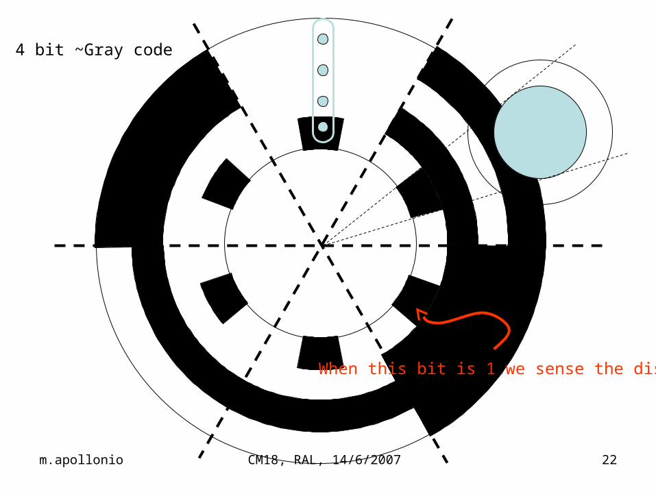
m.apollonio CM18, RAL, 14/6/2007 22
4 bit ~Gray code
When this bit is 1 we sense the disc

m.apollonio CM18, RAL, 14/6/2007 23
2 -switches(check if disc at bottom of TH) 1 optical sensor(check if disc at top of TH)
S1
S2
OS
catc
her
Pb
dis
c +
fra
me
Pb
ext
ern
al a
nn
ulu
s
S. Yang
m.apollonio CM18, RAL, 14/6/2007 24
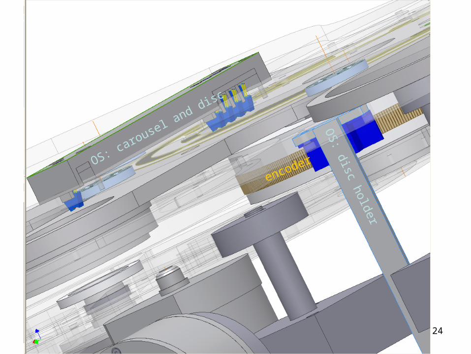
OS: carousel and disc
OS
: disc holder
encoder

m.apollonio CM18, RAL, 14/6/2007 25
0.61 T
0.32 T
0.53 T
B>= 4T
B (T)
Z (m)
R (
m)
motors in the magnetic field can they work ?
m.apollonio CM18, RAL, 14/6/2007 26
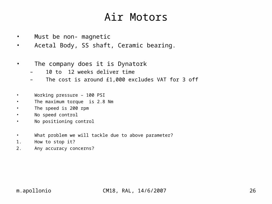
Air Motors
• Must be non- magnetic• Acetal Body, SS shaft, Ceramic bearing.
• The company does it is Dynatork– 10 to 12 weeks deliver time
– The cost is around £1,000 excludes VAT for 3 off
• Working pressure – 100 PSI• The maximum torque is 2.8 Nm• The speed is 200 rpm• No speed control• No positioning control
• What problem we will tackle due to above parameter?
1. How to stop it?
2. Any accuracy concerns?
m.apollonio CM18, RAL, 14/6/2007 27
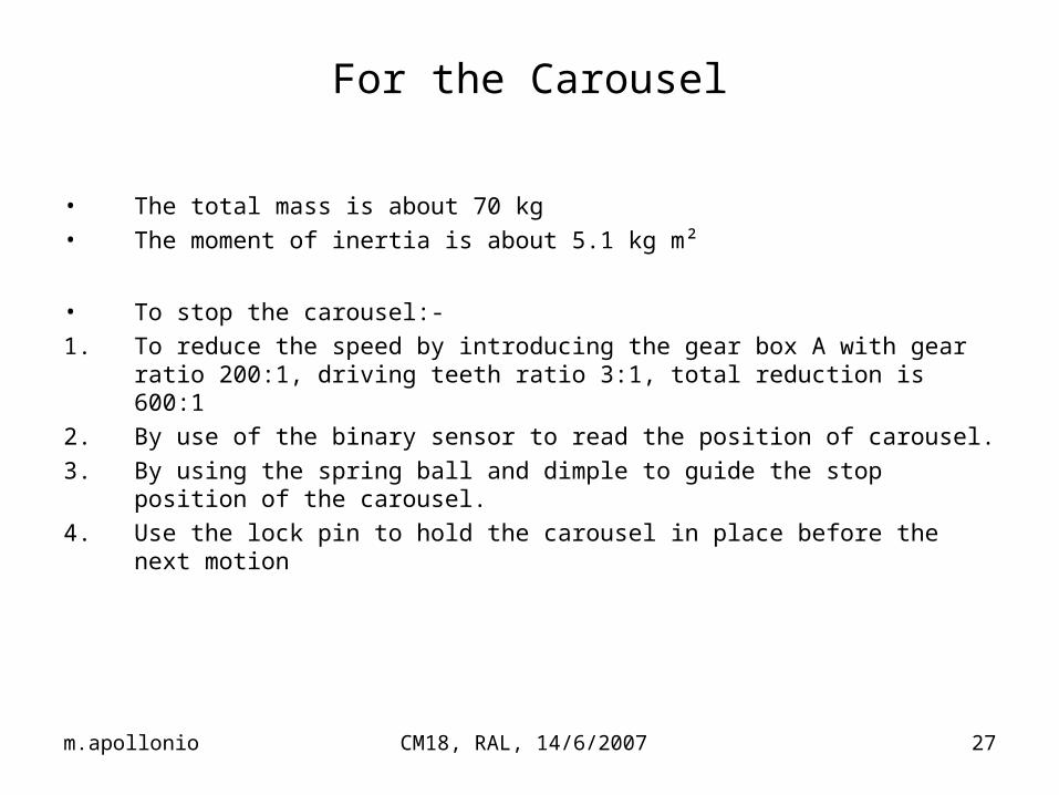
For the Carousel
• The total mass is about 70 kg • The moment of inertia is about 5.1 kg m²
• To stop the carousel:-
1. To reduce the speed by introducing the gear box A with gear ratio 200:1, driving teeth ratio 3:1, total reduction is 600:1
2. By use of the binary sensor to read the position of carousel.
3. By using the spring ball and dimple to guide the stop position of the carousel.
4. Use the lock pin to hold the carousel in place before the next motion

m.apollonio CM18, RAL, 14/6/2007 28
For the 15° disc holder
Drive by the air motor B;
1. To reduce the speed by introducing the gear box B with gear ratio 51:1, teeth driving ratio 7.77 :1, total reduction is 400:1
2. By use of the Heidenhein 4000 series encoder to ensure the very high accuracy of positioning.
m.apollonio CM18, RAL, 14/6/2007 29
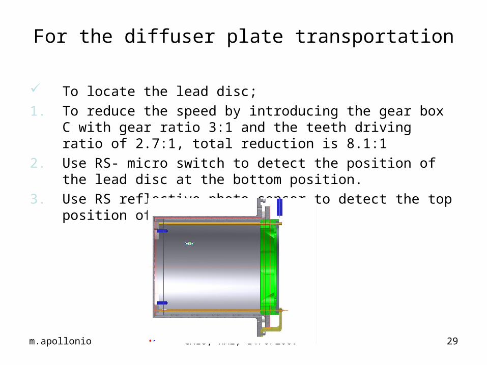
For the diffuser plate transportation
To locate the lead disc;
1. To reduce the speed by introducing the gear box C with gear ratio 3:1 and the teeth driving ratio of 2.7:1, total reduction is 8.1:1
2. Use RS- micro switch to detect the position of the lead disc at the bottom position.
3. Use RS reflective photo sensor to detect the top position of the lead disc.
m.apollonio CM18, RAL, 14/6/2007 30
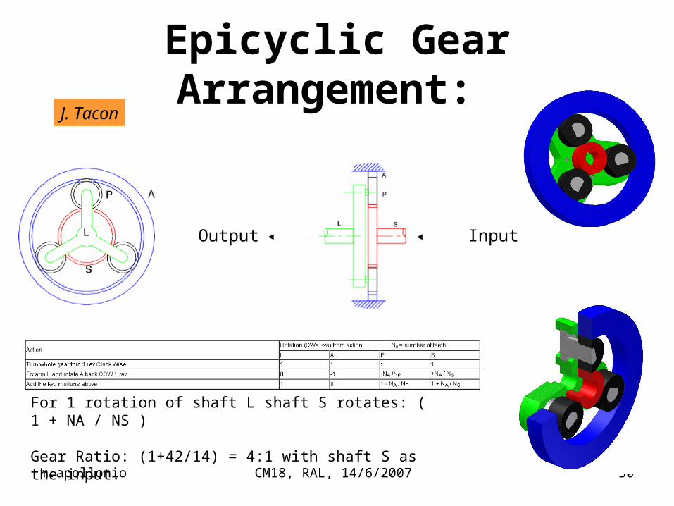
Epicyclic Gear Arrangement:
For 1 rotation of shaft L shaft S rotates: ( 1 + NA / NS )
Gear Ratio: (1+42/14) = 4:1 with shaft S as the input.
InputOutput
J. Tacon

m.apollonio CM18, RAL, 14/6/2007 31
logic & control

m.apollonio CM18, RAL, 14/6/2007 32
Start: go to Nf
(S1&&S2) off?
OS on?
OS on? Which discis in? Nd
Move C to position Nd
Nd = 0
Extract disc
Move catcher to bottom
Move C to position Nf
Insert disc
Go to dummy station
STOP
Move Catcher to top
STOP !!!ERROR
align disc holder:motor ACW (-15 deg abs)
align disc holder:motor CW (+15 deg abs)
Move catcher to bottom
Go to dummy station
Command: set disc-f for run mode
NB: need to know WHICH disc is in !
Diffuser Control Flow Chart:main cycle
m.apollonio CM18, RAL, 14/6/2007 33
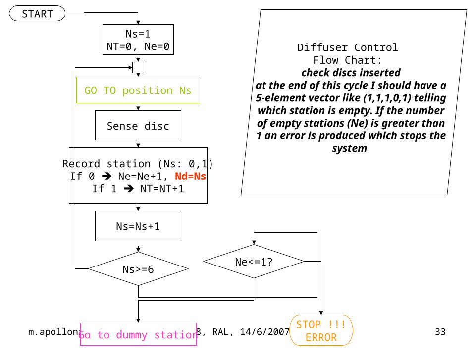
Diffuser Control Flow Chart:
check discs insertedat the end of this cycle I should have a 5-element vector like (1,1,1,0,1) telling which station is empty. If the number
of empty stations (Ne) is greater than 1 an error is produced which stops the
system
Sense disc
START
GO TO position Ns
Record station (Ns: 0,1)If 0 Ne=Ne+1, Nd=Ns
If 1 NT=NT+1
Ns=1NT=0, Ne=0
Ns>=6
Ns=Ns+1
Go to dummy station
Ne<=1?
STOP !!!ERROR

m.apollonio CM18, RAL, 14/6/2007 34
Diffuser Control Flow Chart:
move C to position NdRotate CAROUSEL C.W.
(till OS fires Nd)Turn ON motor (+A)
STOP
START
OS firing on mark Nd?
1. STOP motor (A) 2. Push BR-PIN3. Start timer
1. release BR-PIN
t>3 s?
OS reads Nd?
STOP !!!ERROR
m.apollonio CM18, RAL, 14/6/2007 35
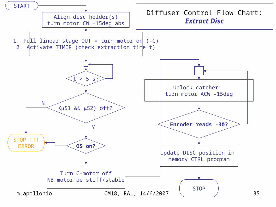
Diffuser Control Flow Chart:Extract Disc
STOP
START
t > 5 s?
1. Pull linear stage OUT = turn motor on (-C)2. Activate TIMER (check extraction time t)
S1 && S2) off?
STOP !!!ERROR OS on?
Turn C-motor offNB motor be stiff/stable
Unlock catcher: turn motor ACW -15deg
Encoder reads -30?
Update DISC position in memory CTRL program
Y
N
Align disc holder(s)turn motor CW +15deg abs

m.apollonio CM18, RAL, 14/6/2007 36
Diffuser Control Flow Chart:Insert Disc
STOP
START
Encoder +30?
Unlock circular plate:Turn motor CW +15 deg
STOP !!!ERROR
Turn B-motor off (B)Turn on (+C):
• Push linear stage• Activate timer
t > 5 s?
OS off?
Register DISC POSITION in memory for the CTRL PROGRAM
S1 || S2) on?
Turn C-motor off
Y
N
m.apollonio CM18, RAL, 14/6/2007 37
Integration
m.apollonio CM18, RAL, 14/6/2007 38
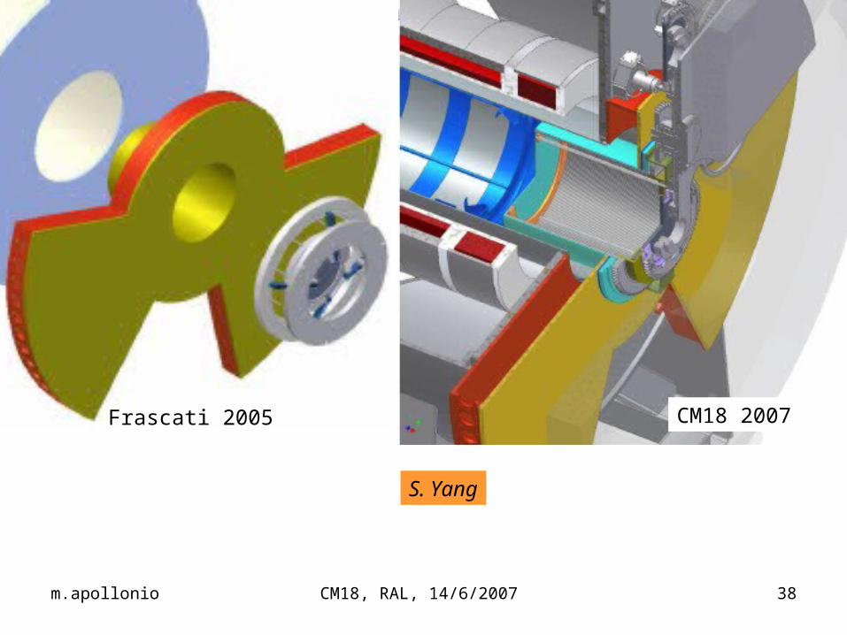
S. Yang
Frascati 2005 CM18 2007

m.apollonio CM18, RAL, 14/6/2007 39
Quench Studies
m.apollonio CM18, RAL, 14/6/2007 40
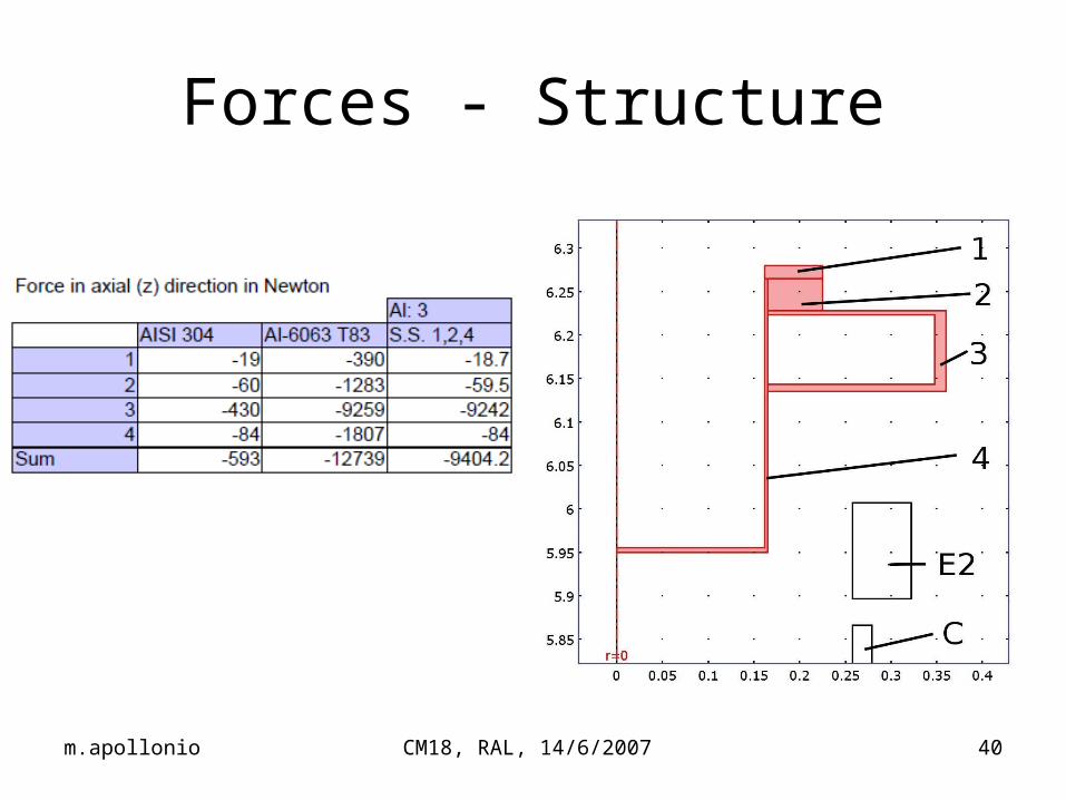
Forces - Structure
m.apollonio CM18, RAL, 14/6/2007 41
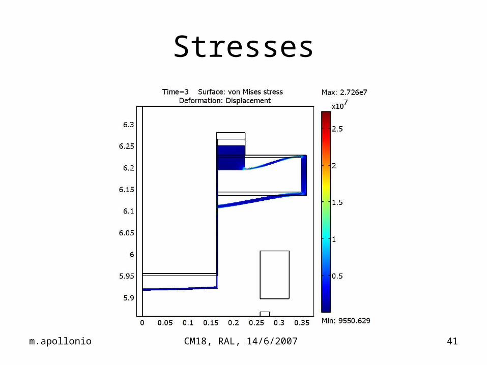
Stresses
m.apollonio CM18, RAL, 14/6/2007 42
Conclusions
m.apollonio CM18, RAL, 14/6/2007 43
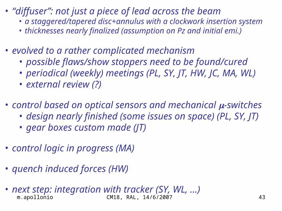
• “diffuser”: not just a piece of lead across the beam• a staggered/tapered disc+annulus with a clockwork insertion system• thicknesses nearly finalized (assumption on Pz and initial emi.)
• evolved to a rather complicated mechanism • possible flaws/show stoppers need to be found/cured • periodical (weekly) meetings (PL, SY, JT, HW, JC, MA, WL)• external review (?)
• control based on optical sensors and mechanical -switches• design nearly finished (some issues on space) (PL, SY, JT)• gear boxes custom made (JT)
• control logic in progress (MA)
• quench induced forces (HW)
• next step: integration with tracker (SY, WL, …)


![The MICE Experiment · 2013. 6. 10. · experiment (MICE) [1] is under development at the Rutherford Appleton Laboratory (UK). The muon beam-line has been commissioned, and beams](https://static.documents.pub/doc/80x56/60df418f2257450db016b45d/the-mice-experiment-2013-6-10-experiment-mice-1-is-under-development-at.jpg)


