MICE Target Shaft Joint Change MICE Target Ti shaft » Baseline stock material = drawn tube lower joined to solid upper (rather than manufacture from solid) » Baseline joint – 4° Taper fit, joins at roomT with no galling / seizure between parts – Electron Beam full 360° orbital weld (fine weld, relatively low heat, accurate) » 2 parallel methods for manufacture of shaft were undertaken – Weld together stock materials and grind down to size – Pre-grind shaft pieces and join these accurate parts
Transcript
MICE Target Shaft Joint Change MICE Target Ti shaft
» Baseline stock material = drawn tube lower joined to solid upper (rather than manufacture from solid)
» Baseline joint– 4° Taper fit, joins at roomT with no galling / seizure between
parts
– Electron Beam full 360° orbital weld (fine weld, relatively low heat, accurate)
» 2 parallel methods for manufacture of shaft were undertaken
– Weld together stock materials and grind down to size
– Pre-grind shaft pieces and join these accurate parts
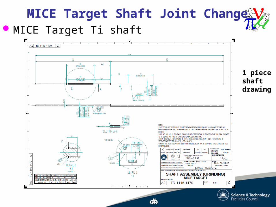
MICE Target Shaft Joint Change MICE Target Ti shaft
1 piece shaft drawing
MICE Target Shaft Joint Change Weld then grind stock materials
» Predicted issue– Poor concentricity between OD & ID of tube and/or OD of
lower and upper shafts (6mm & 4mm)– Concentricity required = 20m over bearing region and 50 m
overall between upper & lower shafts– Actual concentricity achieved >> 100m between upper and
lower shafts, so out of specification (centreless grinding technique)
» Unexpected issue– Grinders ground part way through weld, one shaft fell apart
» No resolution for these problems
MICE Target Shaft Joint Change Pre-grind and join accurate parts
» Predicted issue– Welding might distort shaft in the middle
– Stock material orbital weld did distort significantly at weld Cannot achieve even width of weld over 360°
– Find alternative weld type or method to join
» Alternatives– Through-hole type
– Large spot weld 0.9mm deep
– Use interference fit rather than taper fit
MICE Target Shaft Joint Change Change to joint from taper fit
» 10m parallel Interference fit– Joints made with 10m of parallel
interference– If pressed together at roomT likely to
gall, push off centre and/or seize– Borrowed precision jig for alignment– Used heat hot air gun with
thermocouple to 250°C on socket, and nitrogen for -197°C on plug before assembling (quickly). Interference created as they reach roomT
Features of Upgraded Design Results of weld trial
» Ease of manufacture / weld– Difficulty moved from machining accurate matched tapers
to maintaining tight interference tolerances on parallel socket and plug = ~ no difference
– No negative feedback from EB welding, though plastic bushes in weld jig exhibited melting with through-hole weld indicating more heating of the parts being joined
» Deformation– Measured run-out of shafts before and after weld
– Through-hole distorted significantly (>200 m)
– Spot weld no difference
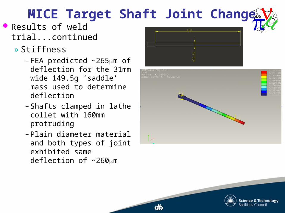
MICE Target Shaft Joint Change Results of weld
trial...continued» Stiffness
– FEA predicted ~265m of deflection for the 31mm wide 149.5g ‘saddle’ mass used to determine deflection
– Shafts clamped in lathe collet with 160mm protruding
– Plain diameter material and both types of joint exhibited same deflection of ~260m
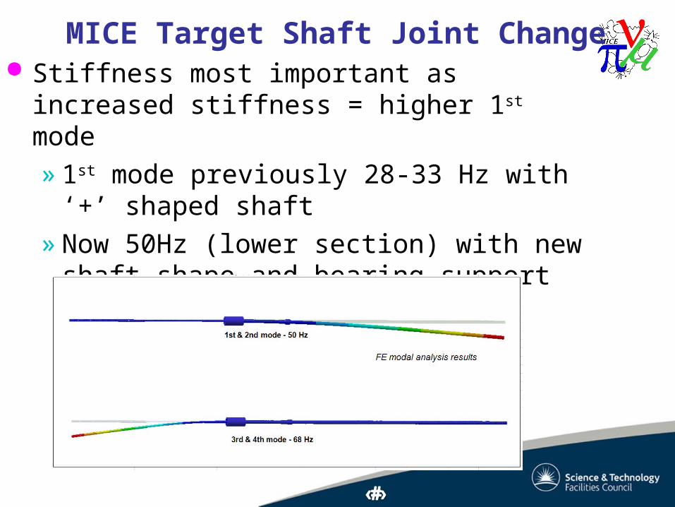
MICE Target Shaft Joint Change Stiffness most important as increased stiffness =
» Can do tensile test on 2 types of joint but knowledge of tensile strength unlikely to enable failure prediction, most likely to fail by fatigue
» Fatigue difficult to determine outside of the assembly & actual operating conditions due to subtleties in loading conditions, only tests in actual situation give valid results, i.e. offline running.
MICE Target Shaft Joint Change Conclusion
» Orbital EB weld joint creates too much distortion for accurate joining of pre-ground parts
» Of 2 types of alternative joint a parallel interference plug and socket with spot weld to secure = most appropriate
– No problems with manufacture or welding
– No perceptible distortion
– As stiff as machining from solid
– Fatigue life to be tested in offline running
» QC discussed with EB welder, pre-production samples (PPS) will be cross-sectioned & micrographed, as was original QC with orbital weld