Copyright© 2018 by Turbomachinery Laboratory, Texas A&M Engineering Experiment Station
BEST PRACTICES FOR CARTRIDGE MECHANICAL SEAL INSTALLATIONS
Michael Huebner
Principal Engineer
Flowserve Corporation
Pasadena, TX, USA
Michael Huebner is a Principal Engineer at Flowserve Corporation in Pasadena, TX. He has over 30 years of
experience working with mechanical seal design, sealing systems, centrifugal pumps, and fluid handling equipment. Mr.
Huebner is a member of ASME, the API 682 Task Force, the ASME B73 Committee and the Texas A&M Pump
Symposium Advisory Committee.
ABSTRACT
The reliability of a mechanical seal depends on more than the design of the seal itself. It also depends heavily on the practices used to
install the mechanical seal into the centrifugal pump or other equipment. The actual installation may occur in a controlled environment
such as a factory or repair shop or it may occur out in the field in an installed pump. The people performing the installation range from
skilled workers with significant experience with seals to general mechanics who have had little exposure to seals. Regardless of the
situation, the steps taken during the installation process set the foundation for the ultimate success of the seal in operation.
Different pump and seal designs may require different installation procedures but there are several key elements that are common
across all installations. These include inspection of the equipment, general requirements for equipment condition, preparation for
installation, installing the seal, setting the seal drive, removal of setting/shipping fixtures, and connecting the piping plan. While each
of the steps is deceptively simple, the ability to identify and correct problems during the installation is critical.
INTRODUCTION
Mechanical seals provide one of the most common solutions for
sealing the rotating shaft in a centrifugal pump and other types or
rotating, fluid handling equipment. Purchasers and end users can find
information on mechanical seals from a wide range of sources. There
is a large body of literature discussing different seal designs and the
benefits and limitations of each of these options. There are also
industry standards defining seal piping plans along with guidance from
industry on the best practices for selection and operation of these
sealing system. There is however one critical step in the life cycle of
mechanical seals that has evaded users’ attention - installation.
The activities that take place between opening a shipping container
with a seal and tightening the final screws or bolts is often loosely identified
as the seal installation. In reality, the seal installation extends both before and after these activities. In many cases, the events that
occur outside of the commonly considered seal installation steps are the most impactful for the success of the seal. Understanding the
requirements of the entire sealing system will improve the chances that the seal will be installed correctly and have the highest
reliability in operation.
Figure 1 OH1 style centrifugal pump
Copyright© 2018 by Turbomachinery Laboratory, Texas A&M Engineering Experiment Station
BASIC SEAL DESIGN
Component Seals
Seal installation is often categorized by the basic design of the seal: a component seal or a cartridge seal. A component seal is a seal
design where many of the components are provided as loose, individual parts. These seals are often supplied by the seal OEM with all
of the parts provided in one box. This makes the job of identifying the required components easier for the end user. In other cases,
however, the end user may stock the components for multiple seals as individual components which allows for greater flexibility in
changing materials or for only replacing specific components during a seal repair.
A component seal was the most commonly supplied seal design when mechanical seals were first adopted by industry. Mechanical
seals were seen as a direct replacement for packing. Most pump OEMs considered the mechanical seal as only a sealing device that
would simply install into the stuffing box and be mounted onto a pump sleeve and into a pump gland. The loose components would
arrive at the pump OEMs facility and be installed as part of the pump assembly.
One of the greatest challenges with component seals is that the success of the installation is greatly impacted by the skill of the
installer and processes used during installation. In a pump OEM environment, there is a higher likelihood that there will be skilled
technicians and a clean environment during installation. To install a component seal, the pump often had to be partially assembled,
lines scribed on sleeves, offsets measured, components tightened, gaskets installed, and glands bolts tightened. During the process, the
seals, especially the seal faces, must have been kept clean and free from contamination. While this process was largely successful at
the OEMs facility, there were significantly greater challenges and a lower success rate at end user’s facilities or in the field.
Component seals continue to be a very large market segment for many seal OEMs although they are primarily used in lower duty
services and often in less critical applications. Some highly engineered component seals are still used in equipment where the physical
constraints of the equipment design require an extremely small seal or the seals must be integrated into the pump design.
Cartridge Seals
Cartridge seals were introduced to reduce the complexity of the seal installation process and to
improve the reliability of the seals in service. A cartridge seal is a design where all of the
critical seal components are pre-assembled at the factory. This provides the most controlled
environment for the seals during assembly. Rather than receiving a box of loose components,
the end user would receive a fully assembled seal. By making the adaptive components part of
the cartridge assembly, the location of the seal parts, the size and location of the required
porting, the mating surfaces for gaskets, and the general design of the seal could be optimized
for seal performance. As a further benefit, the cartridge seal assembly could be tested to ensure
that a defined a level of quality was provided to the purchaser.
The cartridge seal is designed to mate with the pump seal chamber and shaft and, in theory,
should be a simple bolt-on component. This is, in fact, the way many end users view seal
installations. This is often reinforced by the industry when people discuss how easy it is
to install a mechanical seal – “pull out the old seal, stick in the new seal.” Unfortunately,
this statement often turns out to be true. Some end user mechanics have become very
adept at quickly changing out seals that fail frequently. What is not considered is that seals can fail frequently because they are
changed out too quickly. More specifically, the end users may not follow the best practices for installing a mechanical seal and
therefore compromise the performance of the seal before it is even put into service.
DEFINITION
A seal installation is a series of steps required to properly install a seal into a pump. This definition is deceptively simple and so
generic that it provides little to no value to the mechanic. Unfortunately, the seal installation instructions many mechanics receive are
equally generic and fail to provide specific details on the required steps. Seal OEMs provide installation instructions with the
mechanical seals. These instructions are often designed to cover the installation of the most common designs of the seal in the most
common designs of pumps. This is an excellent starting point but these can also fail to capture the full scope of the installation
process.
Figure 2 Typical cartridge seal
Copyright© 2018 by Turbomachinery Laboratory, Texas A&M Engineering Experiment Station
INSPECTION OF EQUIPMENT
A mechanical seal is installed into a centrifugal pump and therefore the pump serves as the foundation for the seal. The basic pump
design, the overall seal chamber dimensions, the specific dimensions of critical fits, and the location of shaft and seal chamber features
are critical to the overall fit of the mechanical seal into the pump. These need to be confirmed prior to installation.
In a larger sense, the overall condition of the pump is a critical consideration in seal performance. Many end users assume that a pump
is in good condition if it can move fluid. As long as the pump hydraulics meet the performance requirements of the operation, the
pump is not inspected. Pumps, however, wear out over time. Bearing fits can become looser. Wear ring clearance can become larger.
Runouts and misalignments can become greater. It is not unusual to find that the most reliable seal performance comes immediately
after a pump overhaul and that seal performance degrades after the pump has been operating for many years.
Before a seal is installed into a pump, the mechanic must inspect the pump to ensure that it is in satisfactory condition and seal design
is correct for the pump.
Step 1 – Obtain Seal Assembly Drawing
The seal assembly drawing is the document that captures the most critical aspects of the seal including the basic seal design,
installation instructions, port locations, and piping plans. This document is required to develop the specific procedures that the
mechanic will use to install the seal. The mechanic must obtain the seal assembly drawing before attempting to install the seal in the
equipment.
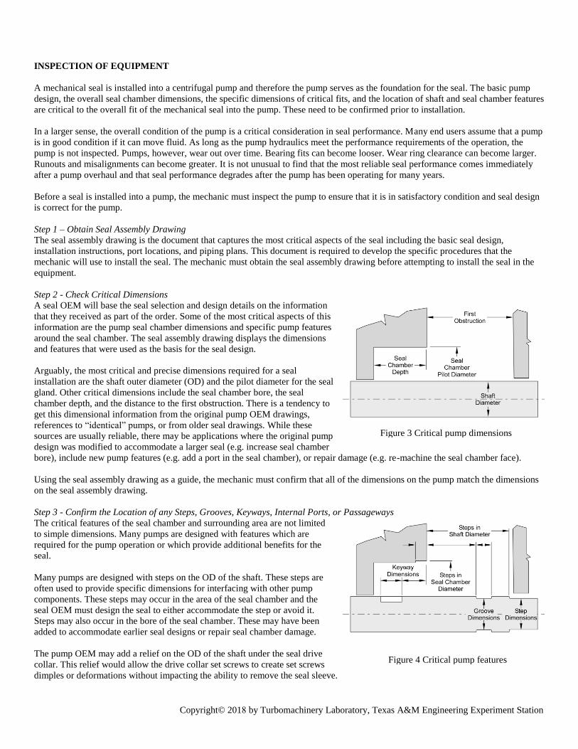
Step 2 - Check Critical Dimensions A seal OEM will base the seal selection and design details on the information
that they received as part of the order. Some of the most critical aspects of this
information are the pump seal chamber dimensions and specific pump features
around the seal chamber. The seal assembly drawing displays the dimensions
and features that were used as the basis for the seal design.
Arguably, the most critical and precise dimensions required for a seal
installation are the shaft outer diameter (OD) and the pilot diameter for the seal
gland. Other critical dimensions include the seal chamber bore, the seal
chamber depth, and the distance to the first obstruction. There is a tendency to
get this dimensional information from the original pump OEM drawings,
references to “identical” pumps, or from older seal drawings. While these
sources are usually reliable, there may be applications where the original pump
design was modified to accommodate a larger seal (e.g. increase seal chamber
bore), include new pump features (e.g. add a port in the seal chamber), or repair damage (e.g. re-machine the seal chamber face).
Using the seal assembly drawing as a guide, the mechanic must confirm that all of the dimensions on the pump match the dimensions
on the seal assembly drawing.
Step 3 - Confirm the Location of any Steps, Grooves, Keyways, Internal Ports, or Passageways
The critical features of the seal chamber and surrounding area are not limited
to simple dimensions. Many pumps are designed with features which are
required for the pump operation or which provide additional benefits for the
seal.
Many pumps are designed with steps on the OD of the shaft. These steps are
often used to provide specific dimensions for interfacing with other pump
components. These steps may occur in the area of the seal chamber and the
seal OEM must design the seal to either accommodate the step or avoid it.
Steps may also occur in the bore of the seal chamber. These may have been
added to accommodate earlier seal designs or repair seal chamber damage.
The pump OEM may add a relief on the OD of the shaft under the seal drive
collar. This relief would allow the drive collar set screws to create set screws
dimples or deformations without impacting the ability to remove the seal sleeve.
Figure 3 Critical pump dimensions
Figure 4 Critical pump features
Copyright© 2018 by Turbomachinery Laboratory, Texas A&M Engineering Experiment Station
For this to be effective, the axial location of the groove must match the location of the set screws on the drive collar.
In some high-pressure applications, the axial hydraulic thrust of the seal sleeve is greater than can be safely accommodated by set
screws in the drive collar. One of the most common ways to increase the axial load capacity of the seal is to use a split ring style drive
collar. These designs utilize a circumferential groove cut into the shaft to carry the axial load. The location and dimensions of the
groove are critical for the seal design and are captured on the seal assembly drawing.
High torque applications can be equally challenging for set screw drive collars. In some applications, a keyway will be cut into the OD
of the shaft and will, with the installed key, provide the torsional drive for the seal sleeve. The location and dimensions of the keyway
and key are also critical for the seal design and are captured on the seal assembly drawing.
On most seal assemblies, the porting required for the seal is incorporated into the seal gland. In this way, the seal OEM can ensure that
the porting location provides the maximum benefit for the seal. In some seal designs however, the porting cannot be designed into the
gland due to space limitations or pump assembly requirements. In these cases, the porting will be incorporated into the pump design
and these features are also captured in the seal assembly drawing.
Using the seal assembly drawing as a guide, the mechanic must confirm that all of the features and dimensions on the pump match the
features and dimensions on the seal assembly drawing.
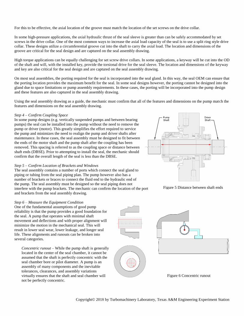
Step 4 – Confirm Coupling Space
In some pump designs (e.g. vertically suspended pumps and between bearing
pumps) the seal can be installed into the pump without the need to remove the
pump or driver (motor). This greatly simplifies the effort required to service
the pump and minimizes the need to realign the pump and driver shafts after
maintenance. In these cases, the seal assembly must be designed to fit between
the ends of the motor shaft and the pump shaft after the coupling has been
removed. This spacing is referred to as the coupling space or distance between
shaft ends (DBSE). Prior to attempting to install the seal, the mechanic should
confirm that the overall length of the seal is less than the DBSE.
Step 5 – Confirm Location of Brackets and Windows
The seal assembly contains a number of ports which connect the seal gland to
piping or tubing from the seal piping plan. The pump however also has a
number of brackets or braces to connect the fluid end to the hydraulic end of
the pump. The seal assembly must be designed so the seal piping does not
interfere with the pump brackets. The mechanic can confirm the location of the port
and brackets from the seal assembly drawing.
Step 6 – Measure the Equipment Condition
One of the fundamental assumptions of good pump
reliability is that the pump provides a good foundation for
the seal. A pump that operates with minimal shaft
movement and deflections and with proper alignment will
minimize the motion in the mechanical seal. This will
result in lower seal wear, lower leakage, and longer seal
life. These alignments and runouts can be broken into
several categories.
Concentric runout – While the pump shaft is generally
located in the center of the seal chamber, it cannot be
assumed that the shaft is perfectly concentric with the
seal chamber bore or pilot diameter. A pump is an
assembly of many components and the inevitable
tolerances, clearances, and assembly variations
virtually ensures that the shaft and seal chamber will
not be perfectly concentric.
Figure 5 Distance between shaft ends
Figure 6 Concentric runout
Copyright© 2018 by Turbomachinery Laboratory, Texas A&M Engineering Experiment Station
Pump and seal OEMs recognize this and have developed standards for acceptable concentricity. API 682, API 610 and ASME
B73 require that the concentricity must be less than 0.005” (0.125mm) TIR. This is measured by placing the dial indicator on the
shaft and measuring the runout on the OD or ID pilot on the seal chamber of the pump.
Perpendicular runout – Perpendicular runout is the
perpendicular deviation of the seal chamber face relative to
the centerline of the rotating shaft. Like concentric runout,
perpendicular runout is the result of multiple components,
manufacturing tolerances, and clearances between the
assembled pump components. Perpendicular runout
however can have a greater impact on seal performance
since some seal designs must continually compensate for
this runout through continuous axial motion of the seal
components. This will result in high wear on seal
components as well as erratic and increased leakage.
Pump and seal OEMs again recognize the need to limit this
type of runout to a minimum practical value. API 682 and
API 610 require the perpendicular runout to be less than
0.0005” per inch of seal chamber bore (0.5 µm/mm) TIR.
This is measured by placing the dial indicator on the shaft
and measuring the runout on the face of the seal chamber.
Bent shaft runout - Bent shaft runout refers to an out-of-concentric condition where the deviation is constant relative to a point on
the OD of the shaft. This can be measured by placing the dial indicator on the seal chamber and measuring the TIR on the OD of
the shaft during one full revolution. Different pump designs and standards address this type of runout. The end user should refer
to the equipment IOM for details on allowable bent shaft runout.
End float or axial play – All pump shafts are located axially
in the pump by means of a thrust bearing. The axial location
is required to ensure that the impeller remains in the correct
location in the pump casing. Axial motion can also have a
negative impact on seal and coupling performance. In most
pump designs, the pump hydraulics create a net axial thrust
in one direction so shaft motion only incurs as the pump
ramps up to steady-state operation. If, however, a pump
does not create a net thrust or the direction of the thrust
changes, the shaft can move continuously back and forth
resulting in additional wear on the seals and other pump
components.
The thrust load is carried from the shaft into the trust
bearings. Different pump designs and application conditions
can dictate the design of the thrust bearings used. These are
typically either rolling element bearings or hydrodynamic
bearings. The type and size of the bearing will dictate how
much axial clearance should be in the assembled rotor and how much axial motion
is possible in service. It is common to measure axial play or end float to determine the health of the bearings and to ensure a
proper pump assembly.
INSPECTION OF THE SEAL CHAMBER
These first steps of the installation process were intended to confirm that the seal is designed correctly for the pump and that the
overall pump condition is adequate for reliable operation. Dimensions and runouts are not the only considerations when installing a
seal. The areas around the seal chamber must also be inspected and prepared for the seal installation. Some of these areas are obvious
while others may be unique to only specific pump designs.
Figure 7 Perpendicular runout
Figure 8 Shaft end float
Copyright© 2018 by Turbomachinery Laboratory, Texas A&M Engineering Experiment Station
Step 7 - Check the Shaft for Burrs or Sharp Edges
Even a shaft which has been machined to the correct dimensions may not be ready for the seal installation. The seal sleeve is
intentionally designed with a very small clearance between the shaft OD and the sleeve ID. This close clearance fit is required to
minimize seal runout and improve seal performance. It also requires that that the surface of the shaft is free from any defects or burrs
which may cause the sleeve to hang-up during installation.
The most common seal sleeve design features a sleeve gasket (e.g. O-ring) on the ID of the sleeve to prevent process from leaking
between the shaft and sleeve. The sleeve gasket is installed with a radial compression to ensure proper sealing during operation.
Unfortunately, this gasket must also slide down a length of the shaft during installation thereby exposing the gasket to any defects or
features on the shaft. This includes features that are intentionally designed into the shaft such as steps, chamfers, grooves, threads, or
keyways. Any sharp edges or burrs can easily damage the sleeve gasket resulting in a leak which will occur as soon as process is
introduced into the pump. The mechanic must inspect the OD of the shaft over the entire path that the seal will slide during
installation. Any sharp edges must be properly prepared to eliminate the possibility of damaging the gasket.
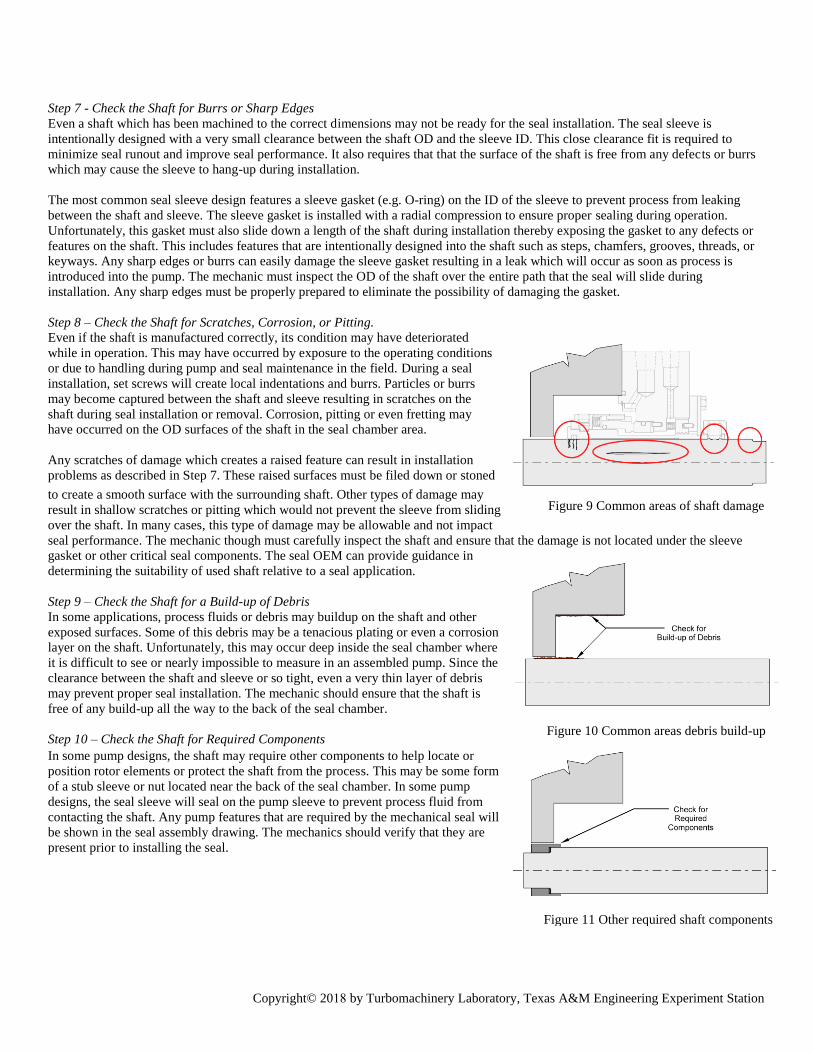
Step 8 – Check the Shaft for Scratches, Corrosion, or Pitting. Even if the shaft is manufactured correctly, its condition may have deteriorated
while in operation. This may have occurred by exposure to the operating conditions
or due to handling during pump and seal maintenance in the field. During a seal
installation, set screws will create local indentations and burrs. Particles or burrs
may become captured between the shaft and sleeve resulting in scratches on the
shaft during seal installation or removal. Corrosion, pitting or even fretting may
have occurred on the OD surfaces of the shaft in the seal chamber area.
Any scratches of damage which creates a raised feature can result in installation
problems as described in Step 7. These raised surfaces must be filed down or stoned
to create a smooth surface with the surrounding shaft. Other types of damage may
result in shallow scratches or pitting which would not prevent the sleeve from sliding
over the shaft. In many cases, this type of damage may be allowable and not impact
seal performance. The mechanic though must carefully inspect the shaft and ensure that the damage is not located under the sleeve
gasket or other critical seal components. The seal OEM can provide guidance in
determining the suitability of used shaft relative to a seal application.
Step 9 – Check the Shaft for a Build-up of Debris In some applications, process fluids or debris may buildup on the shaft and other
exposed surfaces. Some of this debris may be a tenacious plating or even a corrosion
layer on the shaft. Unfortunately, this may occur deep inside the seal chamber where
it is difficult to see or nearly impossible to measure in an assembled pump. Since the
clearance between the shaft and sleeve or so tight, even a very thin layer of debris
may prevent proper seal installation. The mechanic should ensure that the shaft is
free of any build-up all the way to the back of the seal chamber.
Step 10 – Check the Shaft for Required Components In some pump designs, the shaft may require other components to help locate or
position rotor elements or protect the shaft from the process. This may be some form
of a stub sleeve or nut located near the back of the seal chamber. In some pump
designs, the seal sleeve will seal on the pump sleeve to prevent process fluid from
contacting the shaft. Any pump features that are required by the mechanical seal will
be shown in the seal assembly drawing. The mechanics should verify that they are
present prior to installing the seal.
Figure 9 Common areas of shaft damage
Figure 10 Common areas debris build-up
Figure 11 Other required shaft components
Copyright© 2018 by Turbomachinery Laboratory, Texas A&M Engineering Experiment Station
Step 11 – Check the Seal Chamber Face for Damage
Any scratches, gouges, or other damage which results in a raised surface will prevent
the seal gland from properly contacting the seal chamber during installation. This
can result in a cocked seal gland with the same impact as an out-of-perpendicular
alignment. Any raised surfaces or damaged areas must be stoned flat prior the seal
installation.
The seal chamber face not only locates the seal gland, it also provides the sealing
surface for the gland gasket. The gland gasket is normally designed into the seal
gland and is captured against the seal chamber face when the pump gland studs are
tightened. Any damage, scratches, gouges, or corrosion in the gasket area may
prevent the gasket from sealing and result in a seal leak as soon as the pump is
flooded with process. Damage in this area will require re-machining the seal chamber
face to ensure a smooth, flat, perpendicular surface.
Step 12 – Check the Seal Chamber Face for Offset and Axial Misalignment at Split Line Horizontally split case pumps are manufactured with an
upper casing half, pump gasket, and lower casing half bolted
together to create the finished pump. In most manufacturing
processes, the pump is assembled, doweled for location, and
finish machined to ensure proper alignment between the
components. After years of service and multiple
disassembly/assembly cycles, the pump halves may no
longer align perfectly at the split line near the seal chamber.
The two halves may be misaligned axially with a small step
on the face of the seal chamber. This could result in a
cocking of the seal gland during installation. This step can
also result in improper loading of the gland gasket resulting
in a leak at the split line. The upper and lower halves can also
be misaligned horizontally resulting in an out of round seal
chamber bore. This may make it impossible to install the
pilot diameter of the seal gland into the seal chamber during installation.
Both of these conditions can be detected during the runout checks in
Step 6.
Another common issue with horizontally split case pump is an improper alignment of the casing gasket with the critical surfaces of the
seal chamber. The gasket must be precisely aligned with the face of the seal chamber. If the gasket is protruding above or located
below the face of the seal chamber, the O-ring will not seal against this surface resulting in a leak between the gland and seal chamber
face.
Step 13 – Check Seal Chamber for Required Components A seal assembly may require separate components to be installed in the seal
chamber prior to installation. The most commonly required component is a
bushing assembly. This bushing may be required to isolate the seal chamber
from the pump process. In other cases, the bushing may be required to increase
or decrease the pressure in the seal chamber. If a close clearance bushing is
being reused from a previous installation, it is common that it is removed,
inspected, repaired (if required) and re-installed. Using the seal assembly
drawing as a guide, the mechanic must ensure that all required pump or seal
chamber components are installed prior to the seal installation.
All of previous steps are an attempt to ensure that the pump is in a suitable
condition for the installation of the mechanical seal. Unfortunately, these steps
take time and, in some cases, require rework or minor modifications of the
pump. These activities also require a skilled pump mechanic to perform the checks and take the appropriate actions to address any
issues that are identified. Many end users, especially users with unspared equipment, are pressured to return the equipment to
Figure 12 Checking seal chamber face
Figure 13 Mismatch between upper and lower
pump halves at the split line at the seal
chamber
Figure 14 Other required components in the
seal chamber
Copyright© 2018 by Turbomachinery Laboratory, Texas A&M Engineering Experiment Station
operation as quickly as possible. This balance between equipment availability, repair costs, and best repair practices is a challenge for
all pump users.
INSTALLATION
When many end users think of a seal installation, they consider the activity starting with the removal of the seal from the box. That is
indeed the next step of the process. But even these steps require some attention to detail to ensure that the installation is performed
correctly.
Step 14 – Read the Installation Instructions and Specific Installation Requirements from the Seal Assembly Drawing.
Many mechanics have significant experience with pumps and seals in their plants. Many of these mechanics are confident that they do
not need to review the instructions or documentation that comes with the seal. In some cases, this practice has led to seal failures that
could have been easily avoided. The installation instruction can provide specific details which are impossible to check without looking
at the drawing and instructions. Some the details include lubricating specific surfaces, the order of specific steps, and torque values for
installation fastener. Other instructions have safety implications such as connecting specific porting or removing shipping or setting
fixtures. There is never any harm in becoming familiar with the installation requirements prior to starting the installation. In fact, it
may just prevent a failure.
Step 15 - Remove the seal from its packaging
Seals are typically transported in a shipping container or box from the seal OEM to the purchaser or end user. This box is designed to
protect the seal not only during shipment but also during storage, inventory, and transportation to the work site. The seal should
remain in the shipping box until it is time for the installation.
Inspect seal for the correct part number, seal model, and/or material codes – All seal boxes look somewhat similar. They may
have the same basic size and color. They may have similar markings. The only way to ensure that the correct seal has been pulled
for the installation is to check the part numbers and documentation. And then check again. Many seal part numbers are quite long
and complex but each digit of the code has a specific meaning relative to the seal. Make sure that the seal is the correct seal for
this pump.
Some pumps have standardized seal chambers and the end users stock seals which may be used in multiple pumps. Some end
users may have the same seal in stock that differ only in the materials of construction. The same requirement applies that the
mechanic must ensure that the correct seal has been provided for the installation.
Inspect box and seal for damage during storage and transportation – Even though the seal is packaged in a protective shipping
container or box, the seal OEM has little control of the seal once it leaves their facility and damage may have occurred during
transportation and storage. The mechanic must inspect the box and any internal packaging materials for damage before removing
the seal. As the seal is removed from the box, the mechanic should look for signs of damage. If the setting plates are out of
position, there are loose parts in the box, or the assembled seal makes rattling noises, it may indicate that the seal was dropped or
otherwise damaged. Even finding signs like water or condensation in the box may indicate that the seal was not stored properly.
In these cases, the seal should be returned to the OEM for inspection prior to installation.
Locate drawing and other documentation – All seals should be provided with drawings, instructions, or other types of
documentation. The mechanic should confirm that the documentation matches the work order and pump number for the
installation. The part numbers marked on the
seal should also match the documentation.
Ensure that the seal drawing and any
installation instructions are available at the
pump during the actual installation.
Ensure that the direction of rotation of the
shaft matches the direction of rotation of the
seal – Between bearing pumps will have
seals at both ends of the pump casing. When
facing the seals, this results in the shaft
rotating clockwise on one end of the pump and Figure 15 Different direction of rotation on
each end of a between bearing pump
Copyright© 2018 by Turbomachinery Laboratory, Texas A&M Engineering Experiment Station
counterclockwise on the other end. Some seal designs are designed for a specific direction of rotation. This may be required by
face features, pumping devices, or seal porting. Ensure that the direction of the seal matches the direction of rotation of the end of
the pump where it will be installed.
Locate lubricants or other installation tools included with the seals – Some seals are provided with tools to aid with the
installation of the seal. In other cases, installation materials such as a shaft lubricant may be included in the box. Locate any other
tools provided with the seals since they may make installation easier.
Step 16 – Lubricate the Shaft
Lubricating the shaft not only makes the installation of the seal easier, it also protects
the sleeve gasket and minimizes the potential for damage while it is sliding down the
shaft. The lubricant is lightly applied by hand over the length of shaft where the O-ring
will slide during installation. Only a very small amount of lubricant is required. If
excessive lubricant is applied, it will be pushed into the seal chamber and may find its
way onto the seal components or faces during installation or operation of the pump. The
most common lubricants for many applications is a non-reactive grease or light oil. The
end user must make sure that the lubricant selected is compatible with the seal
materials (e.g. gaskets) and is acceptable for contact with the process fluid.
Step 17 - Align drive key slot, install drive key
On some seal designs, a drive key is required to transmit torque from the seal into the shaft. This is accomplished with a keyway in the
shaft and a drive key installed in the keyway. In most designs the keyway is located deep inside the seal chamber. Once the seal
assembly is being installed in the seal chamber, the mechanic cannot see the keyway which makes alignment of the sleeve and key
difficult. It is useful to rotate the shaft so the keyway is located at the top of the shaft (12 o’clock position). When the seal is installed,
the mechanic will know the location of the key. This is made easier if the key
slot in the seal sleeve is also located at the 12 o’clock position.
Step 18 - Orient seal assembly with 12 o’clock at top
All seals designed for horizontal pumps are designed with an intended angular
orientation. Some ports, like the flush port, are located at the top. Other ports,
such as the drain, are always located at the bottom. The seal assembly drawing
will show an end view of the seal assembly with the correct orientation.
Step 19 - If Required, Support the Shaft so it is Concentric with Seal Chamber
Some pump designs require that the bearing housings are removed during the
seal installation. During this time, the pump shaft will not be located in the
center of the seal chamber and it will be impossible to fully install the seal. In
some cases, the shaft may need to be lifted during part of the installation to allow
the seal to slide into position. It is important to install the bearings prior to
releasing the support from the shaft. Most seal setting plates and shipping fixtures are not designed to take the weight of the pump
rotor. Placing the entire weight of the rotor on the seal may damage internal seal components.
Step 20 – Slide the Seal Assembly Down the Shaft
At this point, the seal assembly can be slid down the shaft and into the
seal chamber. In some smaller seals, this may be quite easy.
On larger seals, this may take more effort.
Support the seal if required – Larger seals may be very heavy and
difficult to move along the shaft. Many of these seals are provided
with a connection point for a lifting eye at the 12 o’clock position.
This will allow the mechanic to use a crane to support the seal’s
weight while it is being installed. If this feature is incorporated in
the design, it will be shown on the seal assembly drawing.
Ensure the gland gasket is in position – Before the seal gets to the
seal chamber face, ensure that the gland gasket is in the proper
position (or groove). If this gasket falls out of the groove, the gasket will
Figure 16 Lubricate shaft prior to installation
Figure 17 Orient seal assembly
Figure 18 Slide seal assembly into position
Copyright© 2018 by Turbomachinery Laboratory, Texas A&M Engineering Experiment Station
prevent the seal gland from mating with the seal chamber face. It can also result in damage to the gland gasket resulting in a leak
when process fluid is introduced into the pump.
Align the pump studs with the holes in the gland – Although the general orientation of the seal was checked in Step 18, the
mechanic needs to take care at the seal gland approaches the end of the pump studs. The clearance between the pump studs and
the holes in the gland is relatively tight and may require a slight alignment effort to slide the gland over the studs.
Move slowly over steps or other shaft features – As the seal is being installed, the sleeve gasket is sliding over the shaft surface.
The smooth lubricated shaft will provide little resistance to moving the seal into the seal chamber. There may however be other
features such as steps, grooves, or keyways on the shaft that the sleeve O-ring must slide over. This will increase the resistance
during installation. The mechanic must slowly and carefully move the O-ring over the shaft features. This may require a slight
twisting of the seal to ease the gasket over the features. If the shaft has been properly prepared and lubricated, this can be done
without damaging the sleeve gasket. The mechanic however should never force a sleeve into position.
Step 21 – Slide the Seal Until the Gland Contacts the Seal Chamber Face
The seal assembly should slide freely until the seal gland contacts the seal chamber face. On most assemblies, there will be a very
slight gap between the gland and the seal chamber face due to the gland gasket. This is especially true if the seal has a spiral wound
gasket in this location. If the seal does not slide easily in into this final position, it may indicate that a burr or other debris is causing
the sleeve to hang-up. Some end users have attempted to draw the seal gland into the final position using the pump studs. This can
easily cause internal seal damage and is not recommend. If the seal does not move easily down the shaft, the seal should be removed
and the seal and shaft inspected to determine the cause.
Step 22 - Torque the Pump Gland Bolts/Studs/Nuts
The seal gland must be properly attached to the pump seal chamber
through the available pump studs or other fasteners. This connection
is considered as part of the pressure casing or pressure boundary of
the pump. The pump studs are part of the pump design and the
required torque values can be found in the pump IOM or by
contacting the pump OEM.
The torqueing of the gland fasteners should follow the normal best
practices for torqueing bolted connections. The fasteners should be
torqued to an intermediate value (e.g. 25% of full torque) alternating
between opposing fasteners. After all fasteners are torques to this
intermediate value, they torque should be incremented to 50%, 75%,
and finally 100% in the same manner. If the fasteners are torqued in an
uneven manner, the seal gland can become cocked resulting in a seal failure.
Step 23 - Ensure Final Axial Shaft Position
At this point the seal is in the final axial position and the gland is properly attached to the seal chamber. The next step involves
attaching the seal sleeve to the shaft. Before this can be done, the pump assembly and final shaft adjustments must be completed. In
some pumps, this is the step where the thrust bearings are set. On other pump designs, the axial position of the shaft is adjusted to
provide the highest pump efficiency or to position the rotor properly in the pump casing. All axial adjustments must be completed
before installing the drive collar.
Step 24 – Install the Drive Collar
The drive collar is the seal component which attaches the rotating seal components to the pump shaft. The drive collar will normally
handle all of the torsional load generated by the seal. The drive collar must carry all of the hydraulic and mechanical loads generated
by the seal during operation of the pump. The installation of the drive collar is therefore critical to the success of the seal installation.
Seals are used in a wide variety of the applications with a wide range of operating conditions and equipment constraints. It is therefore
no surprise that seal OEMs have developed a number of different drive collar designs to meet the unique requirements of a specific
application. These can be divided into the general designs listed below and each of these designs have multiple variations. Each of
these variations can also have unique installation requirements. For this reason, the mechanic should reference the installation
instructions provided with the seal for their specific drive collar design.
Figure 19 Torque gland bolts or nuts
Copyright© 2018 by Turbomachinery Laboratory, Texas A&M Engineering Experiment Station
Set screw drive collar – The set screw drive collar is the most popular drive collar design used in cartridge mechanical seals. The
design is relatively simple and is relatively small. It can be positioned anywhere on the shaft and requires no shaft preparation. Is
does however have limitations in high pressure applications and it will create dimples on the pump shaft. The installation
procedure generally only requires that the drive collar set screws are properly torqued during installation.
High temperature drive collar – A high temperature drive collar provides the combined function of a drive collar and sleeve
gasket. This is necessary since high temperature applications require flexible graphite gasketing which must be mechanically
loaded during installation. The drive collar installation procedure therefore requires both tightening screws to compress the
graphite gasket followed by torqueing the drive collar set screws into the shaft.
Split ring drive collar - The split ring drive uses a groove in the shaft to carry the axial loads generated by the seal assembly. This
requires that a split ring is installed during the final stages of the seal installation. Adaptive components must be adjusted to
connect the split ring to the sleeve and set screws must be torqued to attach the drive collar to the shaft. Torque is typically carried
by a keyway on the inboard side of the seal sleeve.
Shrink disc drive collar – A shrink disc drive uses an assembly of tapered discs to convert axial loads in the shrink disc to radial
loads onto the pump shaft. The requires precision dimensions on both the seal sleeve and pump shaft as well as some surface
preparation (cleaning) of the pump shaft. The installation of the shrink disc requires a careful torqueing of the screws on the
assembly.
Step 25 - Remove setting plates
Setting plates are seal components which serve multiple purposes during the
assembly, transportation, and installation of the seal. Like drive collars, seal
OEMs have developed numerous design which each have specific advantages
and disadvantages. In many cases, the actual design used is a matter of choice
of the seal designer.
The setting plates and any other shipping fixtures will be shown on the seal
drawing. All of the shipping or setting components must be removed after the
drive collar installation is complete. In some cases, the setting plate may be
simply slid away from the seal sleeve and tightened down in the retracted
position. This way the components are left attached to the seal gland for future
use. In other cases, the end user may prefer to fully remove the setting plates.
If the setting plates are removed, they should be kept and re-installed prior to
removing the seal from the pump.
POST INSTALLATION INSPECTION
After the seal installation is complete, there are still some steps which should be taken to check for leak paths or other errors in the
installation. There are no procedures which can fully inspect the installed seal nor predict its performance in operation. Some steps
however can provide a level of confidence that the installation was successful.
Step 26 – Rotate the Shaft
In most pumps, the rotor or shaft will rotate freely if the pump is not connected to the motor. Rotors supported by rolling element
bearings will rotate more freely that hydrodynamic bearing but with some effort, even these shafts be rotated by hand. After the seal
installation is complete and the setting plates are removed, attempt to rotate the shaft by hand. There will be slight increase in drag but
the shaft should still rotate. If the shaft rotated before the seal was installed and is binding after the seal installation, the end user
should not start the pump without understanding the cause.
Step 27 – Air Testing the Pump
Air testing an assembled pump is becoming a more common practice for pump maintenance and seal installations. The pump is
blanked off and the pump casing is pressurized with low pressure air. This allows the entire pump and seal assembly to be tested as a
unit. This procedure is typically carried out in a pump shop since the both the suction and discharge flanges of the pump must be
blocked (blind flanged). Any other connections into the pump casing must also be sealed prior to testing. The air test procedures for
seals installed in pumps will be covered in new standards (specifically API 697) which will attempt to standardize both the test
procedures and acceptance criteria for these tests.
Figure 20 Remove setting plates
Copyright© 2018 by Turbomachinery Laboratory, Texas A&M Engineering Experiment Station
Step 28 - Connect Ports on Seal Gland to the Appropriate Connections
Virtually all seal glands are provided with ports which provide the user with
options for various piping plans. The seal installation must also ensure that
the required ports are connected to the appropriate piping or tubing in the
piping plan prior to filling the pump with process fluid. The port locations
and marking can be found on the seal assembly drawing. Other details on the
seal piping plans can be found on the seal assembly drawing or in API 682.
All ports which are unused must be plugged prior to commissioning the
pump
Step 29 - Pressurize the Pump
After the pump has been fully installed and all pump and seal commissioning
procedures have been completed, the pump will be filled with process fluid and
brought up to full pressure. This process can be as simple as opening a valve and
fully pressurizing the pump. In other cases, this may require that a high temperature pump is slowly heated to full operating
temperature over the course of several hours. Regardless of the procedures, the pump and seals should be checked for leakage as the
pump is brought up to pressure.
CONCLUSIONS
There are many different pump designs and a wide variety of seal options which may be applied in the field. In all of these cases
though the mechanical seal must be installed into the pump and the process of the seal installation will directly impact the
performance of the seal. There is no one set of seal installation instructions that covers all seals but there are number of useful steps
which should be a part of any installation procedure. Installations which follow best practices have a higher probability of long term
reliability. Seals which are installed without regards for the condition of the equipment or special installation requirements of the seal
will likely have a lower reliability. Fortunately, the seal OEMs can provide all of the information and support required to incorporate
the best installation practices into the end user’s procedures.
REFERENCES
API Standard 610, 2004, “Centrifugal Pumps for Petroleum, Petrochemical and Natural Gas Industries,” Tenth Edition, American
Petroleum Institute, Washington, D. C.
API Standard 682, 2014, “Pumps – Shaft Sealing Systems for Centrifugal and Rotary Pumps,” Fourth Edition, American Petroleum
Institute, Washington, D.C.
ASME B3.1, 2012, “Specification for Horizontal End Suction Centrifugal Pumps for Chemical Process,” American Society of
Mechanical Engineers, New York, NY
ACKNOWLEDGEMENTS
The author is grateful to Flowserve Corporation for their support in the preparation of this paper and other Pump Symposium
activities. Special thanks to Scott Svendsen for his continued support for technical contributions to the seal industry.
DISCLAIMER
The information provided in the tutorial is intended to provide the reader with important considerations when developing or
performing seal installation procedures. This document cannot however provide specific instructions for any specific field application
since the pump design, seal design, application conditions, and other variables may require specific instructions not included in this
tutorial. For this reason, the author, Flowserve Corporation, TAMU, TEES, or any other persons or entities associated with this paper
assume no liability for the use of information provided or for any damages or consequences associated with the use of this
information. For seal installation requirements for any specific application, please contact the seal OEM for a full engineering review.
Figure 21 Connect all required ports