87
Electron interactions in graphene, Part I – linear response Michael M. Fogler UC San Diego, USA Lecture I @Nanyang Technological University, Singapore, 01/31/13

Electron interactions in graphene, Part I – linear response
Michael M. FoglerUC San Diego, USA
Lecture I @Nanyang Technological University, Singapore, 01/31/13

PROLOG

Nobel Prize 2010
for groundbreaking experiments regarding the two‐dimensional material graphene
A. Geim K. Novoselov

Andre Geim graphene laws2nd Law: There are no interaction effects in
graphene
1st Law:
Theorists are useless

2nd Law of graphene – theorist’s interpretation
A. Tight‐binding model + Electrostatics explain 99% of electron properties
B. Correlations and many‐body effects may be important for 1%
Superconductivity, Magnetism, FQHE, …

EXPERIMENTS

Making Graphene With A Scotch Tape
1atomic layer
20 μm
Start: graphite + some tape Finish: My first graphene sample!

Optical conductivity• No significant deviations from the
“universal” value
Nair et al.2008
4
Kuzmenko et al 2008Nair et al 2008Li et al 2008Mak et al 2011
1 ≲ 0.10
Li et al. 2008

Combined optical data
0 20 40 600.1
1
10
200 400 600 800 2000 4000 6000
E (meV)
71V54V40V28V17V10V
Data from Nair et alData from Mak et alData from Wang et al
/
Z.Q. Li et al, in preparation

Inelastic X‐ray scattering from HOPG graphite
• Polarization function
1 2 4.5
.
.
Im
,eV
• Static dielectric constant
.
Reed et al 2010
Surprisingly large dielectric constant

STM imaging of charged impurities
Wang et alNature 2012
1 2 0.9 2.4
Larger‐than‐expected dielectric constant

INTRO, PART I – MANY‐BODY EFFECTS IN AN ELECTRON GAS

Self‐consistent electrostaticsΦ ?
Need to know the response function:
Total potential
Φ charge density
“screening”Φ Φ ΦΦ

Linear vs. nonlinear response
ΦΦ potentialcharge
, , Φ q, Φ Φ ⋯
, polarization function
• Lecture I (this lecture) • Lecture II

Response functions• Polarization function
,,
Φ ,
• Dielectric function ,
, 12
,
• Longitudinal conductivity ,
, ,
Φ ,Φ ,
,

Random‐phase approximation (RPA)
, , → const
short‐range
, 0 → ∞ → 0metallic‐like screening
, ,
Case of a good metal:
, 12
,

Validity and accuracy of RPA
≪ ≡ ≪ 12
RPA is valid if
In practice, relative accuracy of the RPA is∼ 0.1
For typical 3D metals ∼ 3

Fermi‐liquid theory
2ReΣ
Σ Σ self‐energy
→
→
→
short‐range interaction (Landau function)
Renormalized mass, velocity & dispersion
Renormalized interaction

Renormalization procedure
Λ
Λ“fast”
→ Σ
Λ → Λ Λ
Progressive removal of “fast” degrees of freedom:

Quasiparticle properties within RPA
Σ Σ
→
→
Renormalized mass, velocity & dispersion
self‐energy
(sketch valid for small

INTRO, PART II ‐ GRAPHENE

Tight‐binding model
3.0eV
Wallace, 1941

Electron dispersion of the π‐bands
Dirac cone
Electron structure
Γ
KK′
K
K
K′ K′
M
32 1.0 0.1 10
cm

“Relativistic” Fermi gas
26eV
/∼ ∼ 2.3
→ const
But:Fermi surface = 2 pointsNo metallic screening
0
1 2
Expect RPA ~ 20‐30% accurate?

Velocity at ultralow doping
Other experiments: Li et al 2008; Luican et al 2011; Siegel et al 2011; Hwang 2012
1.0…2.5 10cms
(Slope 0.5 if const
Concentration
Effe
ctiv
e m
ass Elias et al, 2011 Theory: Gonzales et al 1994

What controls interaction strength?
1
is the (effective) dielectric constant of the environment
• Suspended graphene: 1, 2.2
• Graphene on BN substrate: 2.5, 0.9
(assuming the “conventional” value 1.0 10
Examples:

Fermi velocity vs. and Hwang 2012

Response functions• Polarization function
,,
Φ ,
• Dielectric function ,
, 12
,
• Longitudinal conductivity ,
, ,
Φ ,Φ ,
,

Response of free Dirac fermions I
,4
Gonzales et al 1994
1 2 1
Dimensionless ratio
Absorption edge
11
1

Response of free Dirac fermions II• Static dielectric function
, 0 1 2 Ando et al 2002
• Suspended graphene: 2.2, 4.5
• Graphene on BN substrate: 0.9, 2.4
Examples:

Response of free Dirac fermions III• Optical conductivity
lim→ ,
“Universal”4
, , ,
• What else can it be?! Dimensional analysis

Our objective• Compute interaction corrections to density response at arbitrary
/
• Compare with experiments measuring static screening, 0
• Settle the controversy about the optical conductivity, ∞
• Make predictions for intermediate – for future experiments
, 2 , ,
“self‐energy” term “vertex” term
Σ
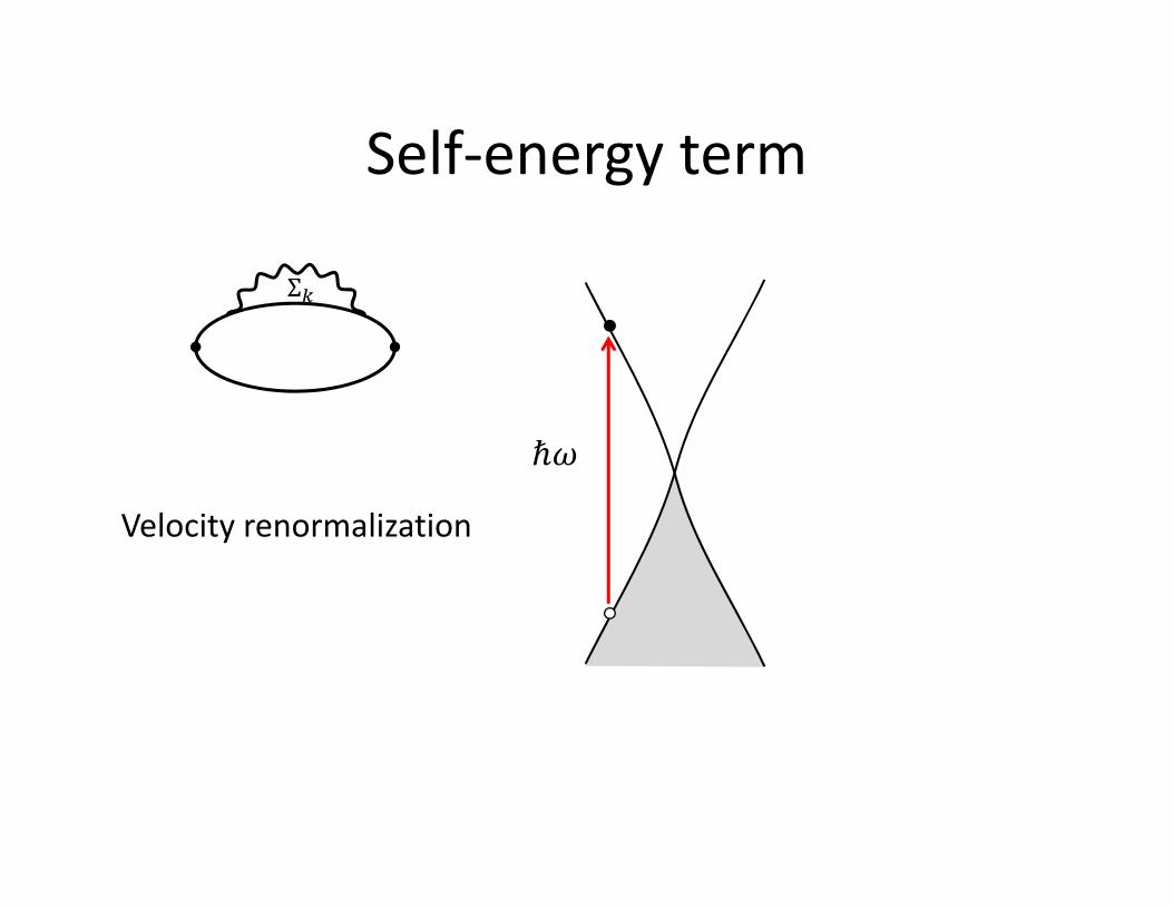
Self‐energy term
Σ
Velocity renormalization

Vertex term
1
2
3
Excitonic effect

MAIN RESULTS

1st interaction correction to polarization
, ,
Self‐energyVertexTotal
Sodemann and MF, arXiv:1206.3519

Dielectric function beyond RPA
0.3
, 0 1 2 0.778
Example: Static dielectric constant
• RPA under‐estimates screening at 1
• RPA over‐estimates screening at 1

COMPARISON WITH EXPERIMENT AND PREVIOUS THEORIES

Static screening – prior work
, 0 1 2 0.778 8 lnΛ
, 0 1 2 0.53
Kotov, Uchoa, Castro Neto 2008
Our result:
Guinea (unpublished) , Polini and Principi (unpublished) – agree with our #
Sodemann and MF, arXiv:1206.3519

Static screening, theory vs. experiment
, 0 1 2 0.778
• Suspended graphene: 2.2 4.5, 8.2, 15.4 .
• Graphene on BN substrate: 0.9 2.4, 3.0, 3.0 0.1
This work:
Sodemann and Fogler, arXiv:1206.3519

Optical limit controversy
1
Mishchenko 2008Sheehy & Schmalian 2008
0.01
Juricic, Vafek & Herbut 2010
Giuliani & Mastropietro 2012
0.26
0?

Bone of contention: self‐energy term
Mishchenko 2008:
14
Juricic, Vafek & Herbut 2010:
Dimensional regularization
84 Σ
4 0 2 Σ 4 lnΛ
2
12
84 Σ
4 0 2
Σ ≃ 41
ln

Dimensional vs. lattice regularization
const ≃ 1
Dimensional regularization yields an artificial and divergent enhancement of the low‐energy density of states
Σ ≃ 41
ln
In contrast to a lattice model:
1 ∼ Λ ≪ 1

Response of graphene III• Experiment: deviations from the
“universal” value are bounded by
Nair et al.2008
• Theory:
4
Kuzmenko et al 2008Nair et al 2008Li et al 2008Mak et al 2011
1
1 ≲ 0.10
Mishchenko 2008Sheehy & Schmalian 2008Juricic, Vafek & Herbut 2010Giuliani & Mastropietro 2012
1
0.01

Arbitrary momenta
, ,
Self‐energyVertexTotal

Near‐field optics of graphene
Si gateSiO2
100‐200 nm
Fei et al, Nano Lett 2011Fei et al., Nature 2012Chen et al., Nature 2012
∼ 6Response at finite momenta:

Beyond the 1st order perturbation theory
Perturbation theory fails near the absorption threshold
New collective mode – excitonicplasmon – has been predicted (Mishchenko et al 2009)
The method of summing higher‐order diagrams is being revised (M.F. and Mishchenko, in preparation)

Summary• You do find many‐body effects in graphene if you look
carefully• Example: 1st‐order correction to the response of
neutral graphene• We computed it for arbitrary momentum and
frequency• Corrected results are in a good agreement with
experiments measuring the static screening

Electron interactions in graphene, Part II – nonlinear screening
Michael M. FoglerUC San Diego, USA
Lecture @Nanyang Technological University, Singapore, 02/01/13

PREVIOUS LECTURE

STM imaging of charged impurities
Wang et al,Nature 2012
1 2 0.9 2.4
Larger‐than‐expected dielectric constant

Self‐consistent electrostaticsΦ ?
Need to know the response function:
Total potential
Φ charge density
“screening”Φ Φ ΦΦ

Linear‐response static screening, theory vs. experiment
1 2 0.778
• Suspended graphene: 2.2 4.5, 8.2, 15.4 .
• Graphene on BN substrate: 0.9 2.4, 3.0, 3.0 0.1
This work:

Linear vs. nonlinear response
ΦΦ potentialcharge
, , Φ q, Φ Φ ⋯
, polarization function
• Lecture I • Lecture II (this lecture)

Plan: nonlinear response to highly charged impurities in graphene
1. Localized charge2. Linear charge3. Plasmonic imaging

COULOMB IMPURITY PROBLEM

Why the Coulomb impurity problem?
• Uncontrolled charged impurities in the substrate
• Intentional doping / gating• Intriguing analogy to atomic collapse and vacuum breakdown in QED

Low‐ vs. high‐ atoms
Energy
+Z
Schwinger, 1950’sZeldovich, 1970’s
+Z
+
1137
1

Atomic collapse
?
• Nonrelativistic case:
min 2
Minimum gives a size of atom
• Relativistic case:
min
Either no bound state or “fall on the center”
+Z
137
+Z
Short‐distance cutoff must be imposed

Interaction strength in graphene
1
is the (effective) dielectric constant of the environment
• Suspended graphene: 1, 2.2• Graphene on BN substrate: 2.5, 0.9
(assuming the “conventional” value 1.0 10
Examples:

Massless fermions in 2D: semiclassicaltrajectories
Shytov et al. 2007 Tunneling through classically forbidden region
escaping hole
collapsing particle

Quantum picture: resonances
Shytov et al. 2007Pereira et al. 2007
12
12
Bare density of states (DOS)
DOS2 | |
Noninteracting Dirac (or lattice) fermions
Khalilov 1998

How large is critical charge??
12 0.55
1 2 0.778
, 2.50.9, 3
.
• Subcritical case
• Supercritical case
Dirac approximation Linear response

Critical charge in graphene: previous work
DiVincenzo et al, Katsnelson,Shytov et al, Pereira et al.
Electron density
r
Subcritical
r
Supercritical Electron density
∼1ln ∼
∼1ln ∼
1

Our work – “hyper”critical charge
M.F., Novikov, Shklovskii, PRB (2007)
STM / AFMtip
Finite distance needed to validate Dirac approximation

New result for “vacuum polarization” around a large Coulomb charge
• New universal result for the structure of the supercritical core
• For this core “squeezes out” the regimes discussed in previous literature
• Such regimes return if
r
Electron density
∼1
∼1/
M.F., Novikov, Shklovskii, PRB (2007)
Supercritical

LINEAR CHARGE PROBLEM

Model
Linear charge density
Φ 2 ln
undopedgraphene sheet

Linear‐response approach fails
ΦΦ
const
Φ1Φ
2ln → ∞
→ ∞
“dielectric‐like” screening

Dielectric function of doped graphene
doped, 0
1
14
undoped, 0
Thomas‐Fermi screening length
12
, 0
2
1 2

Doped vs. undoped case
intraband
Finite density of states (DOS) at the Fermi level enables intraband transitions and metallic‐like screening
interband

Screened Coulomb potential
~1/
→ ∞ → 0 metallic‐like screeningDoped:
0 1 /2 dielectric‐like screeningUndoped:
14
Thomas‐Fermi screening length

Thomas‐Fermi approximation
∼1, Φ ~
12
14
Derivation of the screening length:
Valid for smoothly varying potential Φ

Charge density distribution
∗
∗ ∗ Nonlinear screening length

Reformulate the model
We can replace Φ due to the charge OUT of plane by the equivalent background charge density IN the plane:

Realistic case
Strong interaction implies strong, near‐perfect screening:
charge neutrality

PLASMONIC IMAGING EXPERIMENTS

Near‐field optics of graphene
Si gateSiO2
100‐200 nm
Fei et al, Nano Lett 2011Fei et al., Nature 2012Chen et al., Nature 2012
∼ 6Response at finite momenta:

Plasmon pattern near an edge
Interference of plasmons launched by tip and their reflection off the edge should create λp/2 ‐ periodic nodal lines

Experimental imaging results
Signal oscillates as a function of distance to the edgeLocal plasmon wavelength is twice the oscillation period
Fei et al, 2012
L

Gate‐voltage dependence
0 V- 20 V
10 V20 V30 V
SiO2
s 3(a
.u)
Z. Fei et al., 2012
Other experiments:Chen et al. (2012)Ju et al. (2012)
892cm

Modeling• Graphene: , (no ‐dependence)
• Tip: a collection of point dipoles whose magnitude is
determined self‐consistently
• SiO2 substrate: dielectric constant from experiment
, , , 2D Coulomb
kernel
Plasmon momentum
Objective: extract and damping

Comparison with experiment
• Plasmon momentum increases 30‐50% towards the edge: inhomogeneous doping profile
• Plasmons are damped: | |
0.135
| | | |
0.050.08
0.4 , 5
892 cm
Fei et al, 2012

Conductivity of graphene from near vs. far‐field measurements
Li et al. 2008
← 2
← 0.5
“universal” value
“background”
2
Zhe et al. 2012
/4892cm

Imaging of grain boundaries in CVD graphene
Fei et al. 2013
Grain boundary
(the rest of the figure is cropped)

Charge distribution near grain boundaries
Geometric width is sub‐nmElectronic width is ~100 nm
Fei et al. 2013

Dirac plasmon and the nanoscale infrared response of graphene‐SiO2interfaceD.N. Basov
University of California, San Diego http://infrared.ucsd.edu/
UT Austin/KITP: I. Sodemann
Acknowledgments
UCSD: Z. Fei, G. Andreev, A. McLeod,M. Wagner, D. Basov
BU/NUS: A. Rodin, A. Castro Neto
Support: NSF, UCOP, ONR


