465 AGH DRILLING, OIL, GAS Vol. 34 No. 2 2017 http://dx.doi.org/10.7494/drill.2017.34.2.465 * Keilir Institute of Technology, Reykjanesbar, Iceland ** ISOR Iceland Geosurvey *** University of Stavanger, Faculty of Technology and Natural Science **** AGH University of Science and Technology, Faculty of Drilling, Oil and Gas, Krakow, Poland ***** The paper was created within statute studies at the Faculty of Drilling, Oil and Gas at AGH University of Science and Technology in Krakow, Poland. Grant No. 11.11.190.555 Michał Kruszewski* , ****, Sverrir Thorhallsson**, Mohsen Assadi***, Tomasz Śliwa**** SLIMHOLE WELL CASING DESIGN FOR HIGH-TEMPERATURE GEOTHERMAL EXPLORATION AND RESERVOIR ASSESSMENT***** 1. INTRODUCTION Slimhole drilling technology, as low cost alternative for exploration wells, can play an important role when addressing issues related to reservoir assessment for geothermal energy exploration in new areas. Beside the advantage of lower cost, slimhole technology reduces the environmental impact of field exploration and resource assessment. Wells with diameter less than 6 inches (152.4 mm) are defined as slimholes and they are less costly than normal production-size holes due to reduced cost of crew, rigs, cementing, drilling fluids, casing and tubing. This technology can be easily applied in remote areas, where helicopter-portable rigs can be used. Most of the technologies used in geothermal industry are adopted form Oil and Gas industry with some modifications. However, geothermal reservoir conditions are much different from oil and gas reser- voirs, where steam/water at high temperature has to be produced in large quantities and thus large casing diameters and open hole sections are required for large scale utiliza- tion [1]. Wells with smaller in diameter can, however, be used for exploration drilling to
Transcript
465
����������������� � �� �������� �� ����� �� ����
http://dx.doi.org/10.7494/drill.2017.34.2.465
* Keilir Institute of Technology, Reykjanesbar, Iceland** ISOR Iceland Geosurvey
*** University of Stavanger, Faculty of Technology and Natural Science**** AGH University of Science and Technology, Faculty of Drilling, Oil and Gas, Krakow, Poland
***** The paper was created within statute studies at the Faculty of Drilling, Oil and Gas at AGHUniversity of Science and Technology in Krakow, Poland. Grant No. 11.11.190.555
Michał Kruszewski*, ****, Sverrir Thorhallsson**,Mohsen Assadi***, Tomasz Śliwa****
SLIMHOLE WELL CASING DESIGNFOR HIGH-TEMPERATURE GEOTHERMAL EXPLORATION
AND RESERVOIR ASSESSMENT*****
1. INTRODUCTION
Slimhole drilling technology, as low cost alternative for exploration wells, can playan important role when addressing issues related to reservoir assessment for geothermalenergy exploration in new areas. Beside the advantage of lower cost, slimhole technologyreduces the environmental impact of field exploration and resource assessment. Wellswith diameter less than 6 inches (152.4 mm) are defined as slimholes and they are lesscostly than normal production-size holes due to reduced cost of crew, rigs, cementing,drilling fluids, casing and tubing. This technology can be easily applied in remoteareas, where helicopter-portable rigs can be used. Most of the technologies used ingeothermal industry are adopted form Oil and Gas industry with some modifications.However, geothermal reservoir conditions are much different from oil and gas reser-voirs, where steam/water at high temperature has to be produced in large quantities andthus large casing diameters and open hole sections are required for large scale utiliza-tion [1]. Wells with smaller in diameter can, however, be used for exploration drilling to
466
confirm the resource. Slimhole technology is adopted from already established tech-niques from deep-water wells, mineral exploration and geotechnical investigations [2].Slim wells can be utilized not only in high-temperature reservoirs. In Poland, threeexploratory slim wells of 4 inch (101.6 mm) diameter are being investigated for geother-mal reservoir assessment in Podkarpackie Voivodeship in southeastern Poland. Thesewells are planned to exploit geothermal waters of temperature from 70 to 80°C fromdepths of around 2000 m.
2. RESERVOIR CONDITIONS IN HIGH-TEMPERATURE WELLS
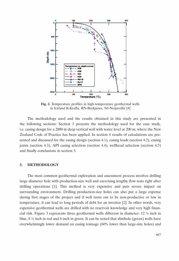
High-temperature drilling in Iceland has shown that bottom hole pressures andtemperatures often follow the Boiling Point Depth (BPD) curve, assuming that water isboiling at any depth in the water filled well [3], as shown in Figure 1. Saturation con-ditions are compared to the measured temperature and pressure (TP) values in a wellthat is heating-up after drilling. The figure indicates that the measured pressure andtemperature follow saturation pressure and temperature for most of the well depths,approximately from 600 to 1700 m. Cooling near the bottom of the well is caused by coldwater pumping from the time of stimulating after drilling, as the well is still heating-up.Boiling point values were calculated using “steam tables” from the X-steam program,Excel add-in. Temperature profiles during drilling operations or while shut-in are quitedifferent from temperatures while heating-up after drilling [4]. Also, as shown in Figure 2,temperatures of various Icelandic geothermal wells are in agreement with the BPDcurve, with some even exceeding boiling point (supercritical conditions – scope of Ice-land Deep Drilling Project) [1].
Fig. 1. Measured temperatures (a) and pressures (b) with saturation conditionsin Icelandic high-temperature well (data provided by Sverrir Thorhallsson)
a) b)
467
Fig. 2. Temperature profiles in high-temperature geothermal wellsin Iceland K-Krafla, RN-Reykjanes, NJ-Nesjavellir [4]
The methodology used and the results obtained in this study are presented inthe following sections: Section 3 presents the methodology used for the case study,i.e. casing design for a 2000 m deep vertical well with water level at 200 m, where the NewZealand Code of Practice has been applied. In section 4 results of calculations are pre-sented and discussed for the casing design (section 4.1), casing loads (section 4.2), casingjoints (section 4.3), API casing selection (section 4.4), wellhead selection (section 4.5)and finally conclusions in section 5.
3. METHODOLOGY
The most common geothermal exploration and assessment process involves drillinglarge diameter hole with production-size well and exercising lengthy flow tests right afterdrilling operations [1]. This method is very expensive and puts severe impact onsurrounding environment. Drilling production-size holes can also put a large expenseduring first stages of the project and if well turns out to be non-productive or low intemperature, it can lead to long periods of debt for an investor [2]. In other words, veryexpensive geothermal wells are drilled with no reservoir knowledge and very high finan-cial risk. Figure 3 represents three geothermal wells different in diameter: 12 ¼ inch inblue, 8 ½ inch in red and 6 inch in green. It can be noted that slimhole (green) wells haveoverwhelmingly lower demand on casing tonnage (60� lower than large-size holes) and
468
cement amount (69� lower than large-size holes) and are much smaller in volume (74�lower than large-size holes) which equals to lower amounts of drilling fluid. These cri-teria amount to much lower costs of drilling wells with 6-inch diameter or less. Asfor Sandia National Laboratories report on slimhole drilling, intermediate cost of drill-ing slim wells is around 60� of the large well’s overall costs to equivalent depth [2],where some other sources assume even 25 to 35� [5]. On this account, investor candrill three to four slim wells for the cost of one large-size well for better geothermalreservoir evaluation.
Fig. 3. Comparison of material usage for large size (12 ¼ inch) holes (blue columns),regular size (8 ½ inch) holes (red columns) and wells with 6 inch diameter (green columns)
(data provided by Sverrir Thorhallsson)
Slim wells can be utilized to measure geothermal gradient and pursue flow testingin not yet assessed area. In reservoirs with low-permeability, size of the hole has nosignificant impact on total flow. However in high-permeability reservoirs, there mightbe some restrictions and higher friction losses, limiting total flow. A large number ofresearches made in Japan and USA confirm that flow testing in slim wells turned out tobe equally informative as these in large size wells. Thus, data produced from slimholescan provide good prediction of reservoir productivity [2].
Two different methods of drilling slim wells are described in following paper, coringand rotary drilling (conventional) method. Wireline coring is a common method, sourcedfrom the mineral exploration industry, designed for wells deeper than 300 m. It provideshigh quality core samples that can be used further for evaluation of reservoir conditions.Because of smaller hole diameter (from 2 to 6 inches) with corresponding core diameter(from 1 to 4 inches) and significantly smaller rigs, it can be easily applied for slim wells.Following method is performed by drilling an interval of 1 to 6 meters (depending onthe length of core barrel) and retrieving the drill string each time with breaking the core
469
just behind the bit. Next, wireline is run down to the core sample and it is retrievedwith its inner tube. Top drive with hydraulic motor or chuck is used to turn the drill string.Due to very fine cutting production during coring and smaller hole volume, wirelinecoring can be carried out without drilling fluid returns (“blind” drilling) [2, 6, 7].The core barrel used for drilling can be then left as a casing string, lowering the cost ofcasing. Conventional rotary drilling method comprises of drill string with tri-cone bit,drill pipes and Bottom Hole Assembly (BHA) with drill collars, crossovers, subs, jars andstabilizers. The drill string is rotated by either rotary table or top drive which appliestorque to the string and allows it to travel downward [2]. This method uses low rotaryspeed and high weight on bit to crush rock formations and produce cuttings, which areonly rock samples available to evaluate geothermal reservoir. As for Sandia report onslimholes, it is more favorable to use coring method, which involves less crew, smallerdrill sites, less mud pumps and produces straighter hole. The ability of drilling “blind”can be also beneficial, as there is no need for mud logging and drilling mud recyclingand thus lower environmental impact. “Blind” drilling can be also exercised through losscirculation zones. Main disadvantages of coring method is longer drilling time, especiallyin sedimentary formations and low availability of rigs able to drill below 1500 m of depth.The most favorable method in not yet assessed reservoirs, advised by authors is combina-tion of coring and rotary method. It is very attractive for areas with softer formationsat the beginning of drilling and relatively harder formation onwards. In summary, geo-logical characteristic of chosen area should be thoroughly evaluated to select the bestdrilling method for slim wells. Following case study has general approach on slim-hole drilling, thus both drilling methods were investigated.
4. RESULTS AND DISCUSSION
4.1. Casing design
Proper casing design is vital for safety and success of the drilling process as wellas future integrity of the well. Casing design includes selecting casing diameter, weight ofcasing (thickness), steel grade and the casing joints which are analyzed for the case studyand presented in the subsequent sections.
The well design includes deciding on the number of casing strings and the corre-sponding selection of the bit and the casing diameters and also the determination ofthe setting casing shoe depths. Typical casing programs for high-temperature wellsinclude conductor casing, surface casing, anchor casing (intermediate casing), produc-tion casing and optional slotted or perforated liner in the open hole section. All casingstrings should be cemented up to the surface, with the exception of liner which can be leftuncemented in open hole. For this case study, casing strings were designed starting from
470
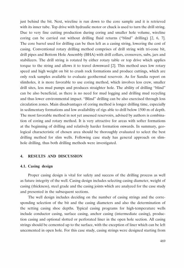
the bottom of the well, proceeding to the top of the well. The boiling curves presented onFigure 4 were used as design criteria for the reservoir conditions [8–10].
Fig. 4. Saturated temperature and pressure versus depth of the well
The design criteria and guidelines for high-temperature geothermal wells have beendescribed in New Zealand Code of Practice from 1991 and the recent update from 2015.The main purposes of casing and liners in high-temperature wells are as follows [8, 9]:
– preventing a hole collapse caused by loose formation material,– anchorage security and support of drilling operations,– containing well fluids and withstand pressures imposed on casing,– preventing contamination of fresh underground water,– countering circulation losses during drilling,– protecting the well from corrosion, erosion and fracturing.
Setting casing depths
When drilling a high-temperature geothermal well in a new area, without any adja-cent wells or geological data, providing TP information as function of depth, a respon-sible assumption needs to be made. To cover the requirements of the “worst case sce-nario”, the BPD conditions should be assumed. To determine the BPD curve for thecase study and make borehole simulations for static (shut-in) and dynamic conditions(flowing), the X-steam program has been used [8].
The new NZS 2015 code determines the minimum depth of the casing strings basedon the pore pressure and fracture gradient, which may be difficult to assess for a new
471
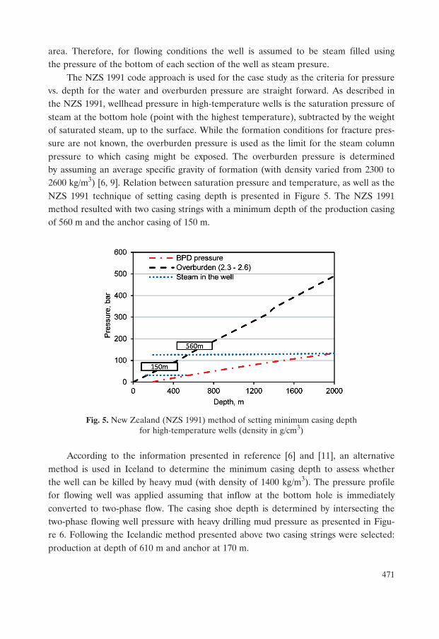
area. Therefore, for flowing conditions the well is assumed to be steam filled usingthe pressure of the bottom of each section of the well as steam presure.
The NZS 1991 code approach is used for the case study as the criteria for pressurevs. depth for the water and overburden pressure are straight forward. As described inthe NZS 1991, wellhead pressure in high-temperature wells is the saturation pressure ofsteam at the bottom hole (point with the highest temperature), subtracted by the weightof saturated steam, up to the surface. While the formation conditions for fracture pres-sure are not known, the overburden pressure is used as the limit for the steam columnpressure to which casing might be exposed. The overburden pressure is determinedby assuming an average specific gravity of formation (with density varied from 2300 to2600 kg/m3) [6, 9]. Relation between saturation pressure and temperature, as well as theNZS 1991 technique of setting casing depth is presented in Figure 5. The NZS 1991method resulted with two casing strings with a minimum depth of the production casingof 560 m and the anchor casing of 150 m.
Fig. 5. New Zealand (NZS 1991) method of setting minimum casing depthfor high-temperature wells (density in g/cm3)
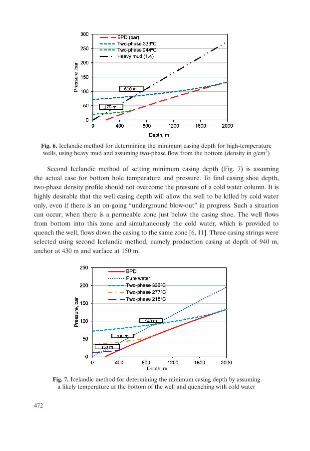
According to the information presented in reference [6] and [11], an alternativemethod is used in Iceland to determine the minimum casing depth to assess whetherthe well can be killed by heavy mud (with density of 1400 kg/m3). The pressure profilefor flowing well was applied assuming that inflow at the bottom hole is immediatelyconverted to two-phase flow. The casing shoe depth is determined by intersecting thetwo-phase flowing well pressure with heavy drilling mud pressure as presented in Figu-re 6. Following the Icelandic method presented above two casing strings were selected:production at depth of 610 m and anchor at 170 m.
472
Fig. 6. Icelandic method for determining the minimum casing depth for high-temperaturewells, using heavy mud and assuming two-phase flow from the bottom (density in g/cm3)
Second Icelandic method of setting minimum casing depth (Fig. 7) is assumingthe actual case for bottom hole temperature and pressure. To find casing shoe depth,two-phase density profile should not overcome the pressure of a cold water column. It ishighly desirable that the well casing depth will allow the well to be killed by cold wateronly, even if there is an on-going “underground blow-out” in progress. Such a situationcan occur, when there is a permeable zone just below the casing shoe. The well flowsfrom bottom into this zone and simultaneously the cold water, which is provided toquench the well, flows down the casing to the same zone [6, 11]. Three casing strings wereselected using second Icelandic method, namely production casing at depth of 940 m,anchor at 430 m and surface at 150 m.
Fig. 7. Icelandic method for determining the minimum casing depth by assuminga likely temperature at the bottom of the well and quenching with cold water
473
As it is rather unlikely that the bottom hole temperature at 2000 m depth reaches333°C, a more probable case was also considered using a bottom hole temperature of280°C. As presented on Figure 8 the fluid turns into two-phase about half way up insidethe flowing well. Following this method for 280°C as a bottom hole temperature,the results for production casing should have a minimum depth of 420 m and anchorcasing at minimum depth of 140 m [6].
Fig. 8. Icelandic method for determining the minimum casing depth for high-temperaturewells by assuming a BPD temperature at the bottom of the well
and quenching with cold water
Comparing results of setting minimum casing depth with the first two methods, itcan be assumed that they lead to roughly similar results. Using the second Icelandicmethod with BPD temperature as bottom hole temperature and cold water as killingfluid, casing program is supposed to be set around 300 m deeper with additional casingstring implemented. The same Icelandic method with assumption of likely temperatureof 280°C (Enthalpy of 1237 kJ/kg) at bottom hole, results in casing depth similar tothe NZS 1991.
After comparison of all methods and results presented above, the final casingsetting depth for this case study was set as follows: mandatory conductor casing at 30 m(pre-installed before the rig assembly), anchor casing at 200 m, production casingat 650 m and slotted liner to the depth of 2000 m hanged on liner hanger with 20 moverlapping. Actual casing setting depths are, however, usually based on minimum tem-perature (e.g. 210°C for high-temperature wells) at the production casing shoe and maybe considerably deeper than the minimum criteria, which would require reassessing ofthe minimum casing depths for the anchor and surface casing.
474
Casing diameter
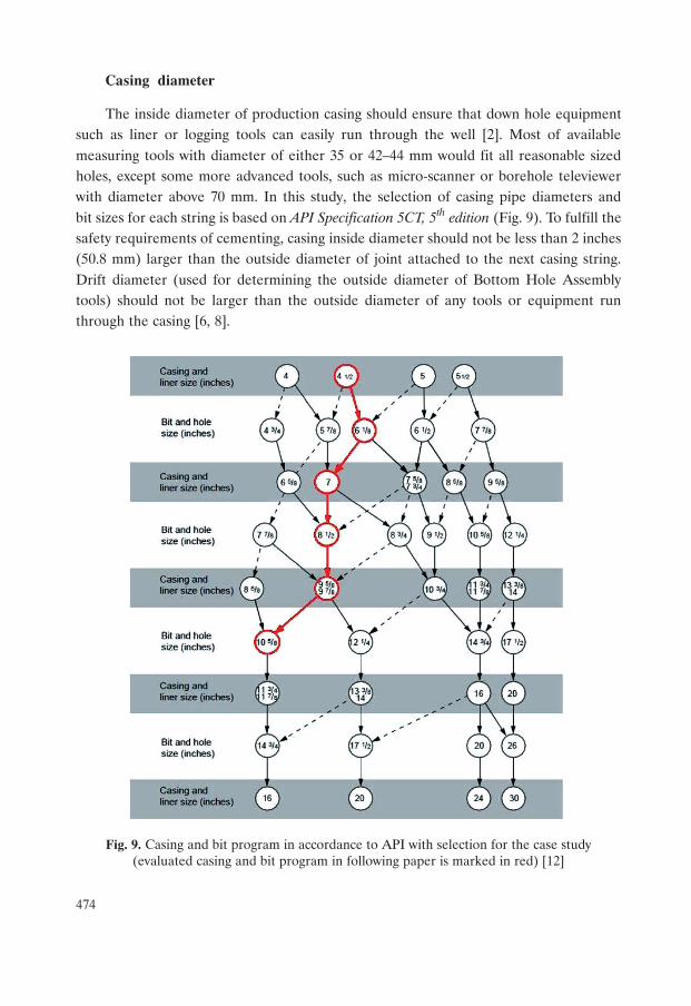
The inside diameter of production casing should ensure that down hole equipmentsuch as liner or logging tools can easily run through the well [2]. Most of availablemeasuring tools with diameter of either 35 or 42–44 mm would fit all reasonable sizedholes, except some more advanced tools, such as micro-scanner or borehole televiewerwith diameter above 70 mm. In this study, the selection of casing pipe diameters andbit sizes for each string is based on API Specification 5CT, 5th edition (Fig. 9). To fulfill thesafety requirements of cementing, casing inside diameter should not be less than 2 inches(50.8 mm) larger than the outside diameter of joint attached to the next casing string.Drift diameter (used for determining the outside diameter of Bottom Hole Assemblytools) should not be larger than the outside diameter of any tools or equipment runthrough the casing [6, 8].
Fig. 9. Casing and bit program in accordance to API with selection for the case study(evaluated casing and bit program in following paper is marked in red) [12]
475
Steel grade and corrosion protection
Low alloy API K-55 (weldable) or L-80 (not weldable) steel type are the mostpreferable choice for high-temperature wells, as they minimize the possibility of failurecaused by hydrogen embrittlement or sulphide stress corrosion [6, 8]. Tensile require-ments for steel grade K-55 are presented in Table 1 [12, 13].
Table 1
Tensile requirements for K-55 casing [14]
Looking at previous research [12] corrosion of the liner is expected to be morecritical than the rest of the casing. To prevent corrosion of liner, which might originatefrom shallower casing, different methods can be applied [8]:
– adding inhibitors to circulating fluid,– implementing larger casing diameter,– application of corrosive resistance coverage onto the casing surface,– different liner material choice, for instance glass fiber.
4.2. Casing loads
Various types of loads occur in the well during running, testing, cementing and pro-duction. These loads occur in axial (compressive and tensile) or radial direction (burstand collapse). For high-temperature wells, the most crucial loads are those caused byinternal pressure and thermal expansion. Corrosion allowance needs to be taken intoconsideration while designing casing. Calculations presented in following sectionsare based on New Zealand Standard 1991 and recent update from 2015, as well as APIstandards. Cement density of 1900 kg/m3 was applied for high-temperature geother-mal wells [3]. Calculations for burst and collapse for the slotted liner were not included,as it is exposed only to axial self-weight compression (if standing on the bottom) or ten-sion (if hanging with liner hanger) and helical buckling [3, 8].
bar 3 790 Minimum yield strength
psi 55 000
bar 5 520 Maximum yield strength
psi 80 000
bar 6 550 Minimum ultimate tensile strength
psi 100 000
476
Collapse pressure
The casing design must ensure that differential pressure between outside and insidethe casing, during running or cementing operations, will not exceed the casing collapseresistance. For running the casing, the inside pressure is set to zero, as the casing isassumed to be empty for the design purposes. However, in practice, casing is periodicallyfilled up with water while being run in the hole and then the collapse differential pres-sure becomes smaller [8, 9, 13].
Collapse pressure during cementing occurs when the annulus is filled with cementslurry and the casing is filled with water. Pressure at surface is assumed to be zero and themaximum collapse pressure at casing shoe is calculated. In this case study, additional 10 barswere added to the resulting collapse pressure for potential pressure loss due to frictionwhile pumping the cement through the annulus. Safety factor of 1.2 was applied [8, 9].
( )C cem c w pP g h P= ρ − ρ ⋅ ⋅ + (1)
C run mP g h= ρ ⋅ ⋅ (2)
casing external collapse pressureDesign factor
net external pressure= (3)
where:PC cem – collapse pressure during cementing, bar,PC run – collapse pressure during running-in with casing, bar,
Pp – pumping pressure, bar,ρw – density of pure (20°C) water, kg/m3,ρc – density of cement, kg/m3,
ρm – density of drilling mud, kg/m3,g – acceleration due to gravity, 9.81 m/s2,h – increment of depth, m.
Burst pressure
Burst pressure, or internal yield is the difference between internal and external wellpressure. Designing for burst must ensure that pressure inside the well will not exceedinternal yield strength limit of casing. While designing for burst during production, pres-sure inside the well is assumed to be column of steam pressure, whereas annulus pressureis the formation pressure (BPD). Calculations were made for surface and casing shoeof each casing. External burst at surface is assumed to be zero. Safety factor of 1.8 andtemperature reduction factor of 0.86 (Tab. 2) was applied.
477
Table 2
Results for burst and collapse calculations applied on anchorand production casing selected from section Setting casing depths, p. 470, using Excel worksheet
Together with collapse pressure, burst pressure dictates the choice of primary casingwall thickness [8]. Results for collapse and burst pressure are presented in Table 2.
( )B prod s fP g h= ρ − ρ ⋅ ⋅ (4)
Anchor casing [bar] Production casing [bar]
Burst
Burst pressure during production
Burst at surface 126.2 126.6
Burst at surface by safety factor of 1.8 227.2 227.9
Pe at surface 0.0 0.0
Pi at surface 126.2 126.6
Burst at shoe 125.2 87.8
Burst at shoe by safety factor of 1.8 225.4 158.0
Pi at shoe 126.2 126.6
Pe at shoe 1.0 38.8
Collapse
Collapse pressure during running of the casing
Collapse at surface 0.0 0.0
Collapse at shoe 20.6 67.0
Collapse at shoe by safety factor 1.2 24.7 80.3
Pe at shoe 20.6 67.0
Pi at shoe 0.0 0.0
Collapse pressure after running of the casing
Collapse at surface 0.0 0.0
Collapse at shoe 27.7 67.4
Collapse at shoe by safety factor 1.2 33.2 80.9
Pe at shoe 37.3 121.2
Pi at shoe 19.6 63.8
478
internal yield strengthDesign factor
differential burst pressure= (5)
where:PB prod – burst pressure during production, bar,
ρs – density of steam column, kg/m3,ρf – density of rock formation, kg/m3.
Combination effects of axial and circumferential tension, while wellhead is fixed tothe production casing are calculated using the equation below. Safety factor of 1.5 wasapplied [8].
( )5
2w
tP d
fD d
⋅= ⋅− (6)
steel yield strengthDesign factor
maximum tensile strength= (7)
where:Pw – maximum wellhead pressure, bar,
d – pipe inside diameter, m,D – pipe outside diameter, m.
Axial Loading before and during cementing
Total tensile load (hookload), while running in and during cementing, appliedon the casing (except conductor casing) are weight of casing in the air plus the weight ofthe casing content, less the buoyant effect resulting from fluids displaced by the casing [8].
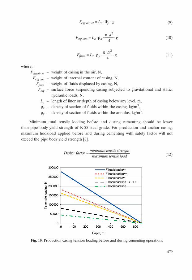
The following different cases were investigated: drilling mud inside the casing andin annulus (m/m), cement inside the casing and drilling mud in annulus (c/m), ce-ment inside the casing and in annulus (c/c) and water inside the casing and cementin annulus (w/c). Typical cementing method was considered, i.e. pumping slurry cementdown through the casing and up to the annulus. This method is better suited for smallerin diameter casing programs. For large in diameter high-temperature wells, inner-stringmethod is more commonly used [1]. Safety factor of 1.8 was applied for the calculated w/chookload. Calculations were made using equations from the NZS 2015 and results arepresented in Figures 10 and 11.
csg csg air wt csg con fluidF F F F= + − (8)
479
csg air wt z pF L W g= ⋅ ⋅ (9)
2
4csg con z xd
F L gπ⋅= ⋅ρ ⋅ ⋅ (10)
2
4fluid z yD
F L gπ⋅= ⋅ρ ⋅ ⋅ (11)
where:Fcsg air wt – weight of casing in the air, N,
Fcsg con – weight of internal content of casing, N,Ffluid – weight of fluids displaced by casing, N,Fcsg – surface force suspending casing subjected to gravitational and static,
hydraulic loads, N,Lz – length of liner or depth of casing below any level, m,ρx – density of section of fluids within the casing, kg/m3,ρy – density of section of fluids within the annulus, kg/m3.
Minimum total tensile loading before and during cementing should be lowerthan pipe body yield strength of K-55 steel grade. For production and anchor casing,maximum hookload applied before and during cementing with safety factor will notexceed the pipe body yield strength [8].
minimum tensile strengthDesign factor
maximum tensile load= (12)
Fig. 10. Production casing tension loading before and during cementing operations
480
Fig. 11. Anchor casing tension loading before and during cementing operations
As presented in Figures 10 and 11, the highest tension loads are applied on casingduring cementing, when cement is inside the casing and drilling mud is in the annulus.The minimum tensile force applied on the casing is when entire volume of cementis displaced into the annulus (w/c). Such conditions were selected for calculation ofthe collapse resistance.
Axial loading after cementing
When designing casing for geothermal well with boiling conditions, it is crucialto consider the temperature effects to allow for the changes in casing steel properties.Thus safety factors from Table 3 should be applied [3]. For design purposes tempera-ture through the pipe is assumed to be constant. Results from calculations are presentedin Table 4.
Table 3
Safety factors concerning temperature effects for casing K-55 [8]
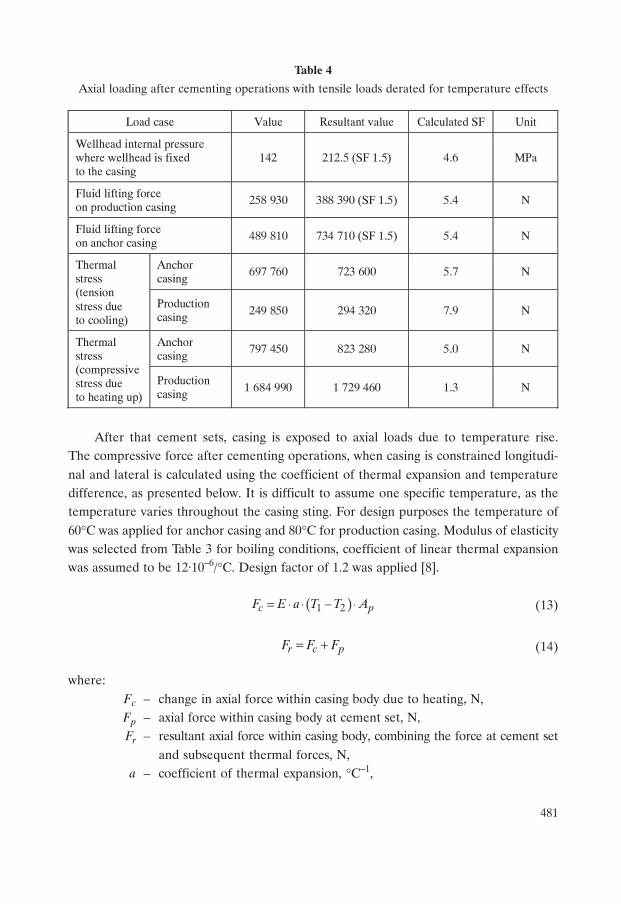
Axial loading after cementing operations with tensile loads derated for temperature effects
After that cement sets, casing is exposed to axial loads due to temperature rise.The compressive force after cementing operations, when casing is constrained longitudi-nal and lateral is calculated using the coefficient of thermal expansion and temperaturedifference, as presented below. It is difficult to assume one specific temperature, as thetemperature varies throughout the casing sting. For design purposes the temperature of60°C was applied for anchor casing and 80°C for production casing. Modulus of elasticitywas selected from Table 3 for boiling conditions, coefficient of linear thermal expansionwas assumed to be 12·10–6/°C. Design factor of 1.2 was applied [8].
( )1 2c pF E a T T A= ⋅ ⋅ − ⋅ (13)
r c pF F F= + (14)
where:Fc – change in axial force within casing body due to heating, N,Fp – axial force within casing body at cement set, N,Fr – resultant axial force within casing body, combining the force at cement set
and subsequent thermal forces, N,a – coefficient of thermal expansion, °C–1,
Load case Value Resultant value Calculated SF Unit
Wellhead internal pressure where wellhead is fixed to the casing
142 212.5 (SF 1.5) 4.6 MPa
Fluid lifting force on production casing
258 930 388 390 (SF 1.5) 5.4 N
Fluid lifting force on anchor casing
489 810 734 710 (SF 1.5) 5.4 N
Anchor casing
697 760 723 600 5.7 N Thermal stress (tension stress due to cooling)
Production casing 249 850 294 320 7.9 N
Anchor casing
797 450 823 280 5.0 N Thermal stress (compressive stress due to heating up)
Production casing 1 684 990 1 729 460 1.3 N
482
E – modulus of elastic, MPa,Ap – cross-sectional area of pipe, m2,T1 – neutral temperature (i.e. temperature of casing at time of grout set), °C,T2 – maximum expected temperature, °C.
Tension loads due to circulation of cooled fluid from the surface during drillingor testing operations is calculated using following equations. Minimum temperatureof 25°C was chosen for anchor casing and 55°C for production casing after cooling ofthe well [8].
( )1 3t pF E a T T A= ⋅ ⋅ − ⋅ (15)
r t pF F F= + (16)
minimum tensile strength of jointDesign Factor
resultant compressive force= (17)
where:Ft – change in axial force within casing body due to cooling, N,T3 – minimum temperature after cooling, °C.
The axial loading (Tab. 4), enforced on top section of casing anchoring and thewellhead (in this case production casing) against the fluid (steam) inside the well is calcu-lated using the follows equation. Safety factor of 1.5 was applied [8].
2
4w wd
F Pπ⋅= ⋅ (18)
anchor casing tensile strengthDesign Factor
rising casing compressive strength= (19)
Initial temperature rise in the well results in increase of the compressive loads inthe cemented casings, which might decrease with time. On the other hand, tensile loadsdue to cooling might increase after installation of the casing strings [8].
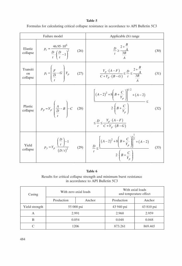
Critical collapse strength for Oilfield Tubular Goods
Critical collapse resistance of K-55 steel grade casing was calculated using APIequations from API Bulletin 5C3, 1989. Following formulas conclude minimum acceptable
483
collapse values, which are determinated by geometrical deviations of casing and yieldstrength of the casing material. Theoretical calculation formals are presented in Table 5,whereas results in Table 6.
5 10 2 16 32.8762 0.10679 10 0.21302 10 0.53132 10p p pA Y Y Y− − −= + ⋅ ⋅ + ⋅ ⋅ − ⋅ ⋅ (20)
6 30.026233 0.50609 10 pB Y−= + ⋅ ⋅ (21)
7 2 13 3465.93 0.030867 0.10483 10 0.36989 10p p pC Y Y Y− −= − + ⋅ − ⋅ ⋅ + ⋅ ⋅ (22)
3
6
2
3
46.95 102
3 3
12 2
p
BA
BA
FB B
BA AYB BAA A
⎛ ⎞⎜ ⎟
⋅ ⋅⎜ ⎟⎜ ⎟+⎝ ⎠
=⎛ ⎞ ⎛ ⎞⎜ ⎟ ⎜ ⎟
⋅ − ⋅ −⎜ ⎟ ⎜ ⎟⎜ ⎟ ⎜ ⎟+ +⎝ ⎠ ⎝ ⎠
(23)
( ) /G F B A= ⋅ (24)
Previous equations are based on zero axial stress, however in normal working condi-tions that is never the case. Considering axial loading (Figs 10 and 11) and temperatureeffects (Tab. 4), new derated yield strength is calculated as follows:
2
1 0.75 0.5 0.8a apa p
p p
S SY Y
Y Y
⎡ ⎤⎛ ⎞⎢ ⎥= ⋅ − ⋅ − ⋅ ⋅⎜ ⎟⎢ ⎥⎜ ⎟⎝ ⎠⎢ ⎥⎣ ⎦
(25)
where:Yp – yield strength of casing, MPa,
Ypa – reduced yield strength of casing by temperature effects and axial stress, MPa,Sa – axial stress, N,
t – pipe wall thickness, m.
484
Table 5
Formulas for calculating critical collapse resistance in accordance to API Bulletin 5C3
Table 6
Results for critical collapse strength and minimum burst resistancein accordance to API Bulletin 5C3
Failure model Applicable D/t range
Elastic collapse
(26)
(30)
Transition
collapse
(27)
(31)
Plastic collapse
(28)
(32)
Yield collapse (29)
(33)
With zero axial loads With axial loads
and temperature effect Casing
Production Anchor Production Anchor
Yield strength 55 000 psi 43 940 psi 43 810 psi
A 2.991 2.960 2.959
B 0.054 0.048 0.048
C 1206 873.261 869.465
6
2
46.95 10
1
⋅=⎛ ⎞⋅ −⎜ ⎟⎝ ⎠
cpD Dt t
2
3
+≥
BD A
BtA
⎛ ⎞⎜ ⎟
= − ⋅⎜ ⎟⎜ ⎟⎜ ⎟⎝ ⎠
t pF
p G YDt
( )( )
2
3
+⋅ −≤ ≤
+ ⋅ −p
p
BY A F D A
BC Y B G tA
⎛ ⎞⎜ ⎟
= ⋅ − −⎜ ⎟⎜ ⎟⎜ ⎟⎝ ⎠
p pA
p Y B CDt
( ) ( )
( )( )
1/ 222 8 2
2
⎛ ⎞⎡ ⎤− + +⎜ ⎟⎢ ⎥ + −⎜ ⎟⎢ ⎥⎝ ⎠⎣ ⎦ ≤
⎛ ⎞⋅ +⎜ ⎟⎜ ⎟⎝ ⎠
⋅ −≤ ≤
+ ⋅ −
p
p
p
p
CA B A
Y
CB
Y
Y A FD
t C Y B G
( )2
1
/
⎛ ⎞ −⎜ ⎟⎝ ⎠= ⋅y p
D
tp Y
D t
( ) ( )
1
222 8 2
2
⎛ ⎞⎡ ⎤− + +⎜ ⎟⎢ ⎥ + −⎜ ⎟⎢ ⎥⎝ ⎠⎣ ⎦≤
⎛ ⎞⋅ +⎜ ⎟⎜ ⎟⎝ ⎠
p
p
CA B A
YD
t CB
Y
485
Table 6 cont.
Minimum burst resistance in accordance to API
To calculate minimum burst resistance of the casing, Barlow’s equation was used [15].Same as collapse resistance, yield strength of the material should also be derated withtemperature coefficient of 0.8 (Tab. 4) and axial loading. Results for minimum burstresistance are shown in Table 6. Thickness of both casing strings was increased in orderto withstand the burst pressure load.
20.875 0.8pa
B resY t
PD
⋅ ⋅⎛ ⎞= ⋅ ⋅⎜ ⎟
⎝ ⎠(34)
4.3. Casing joints
The most common type of casing joints in geothermal industry are API ButtressStandard thread connections (API BTC), with proven strength both in compression andtension. These “trapezoid-shaped” threads are easily accessible and have lower amountof threads per inch [8, 14, 16].
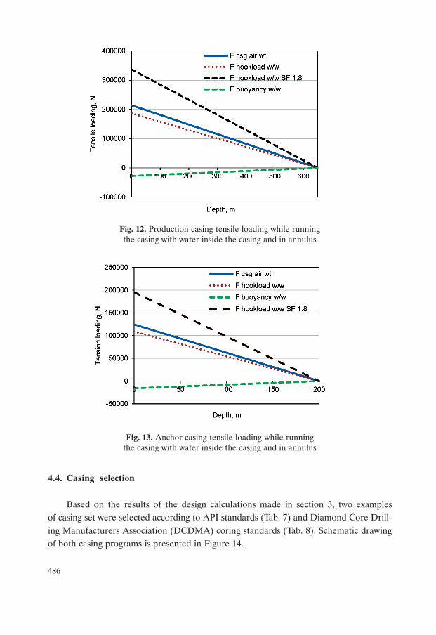
The highest tensile loads on joints are occurring while running the casing. Thuscalculations were made with casing strings filled with pure water inside and outside ofthe pipe (Figs 12 and 13). To meet safety requirements, design factor of 1.8 was applied.Calculated tension loads are minor and are far from exceeding the tensile strength ofthe join (232·103daN for production casing and for anchor casing 411·103daN) [14].
D 21.808 14.301 14.222
F 1.989 2.033 2.033
G 0.036 0.033 0.033
D/t ratio 22.082 22.126 22.082 22.126
Failure model
Plastic Plastic Plastic Plastic
Minimum Burst
Resistance
4 359 psi
30.0 MPa
4 350 psi
30.0 MPa
3 482 psi
24.0 MPa
3 465 psi
23.9 MPa
Collapse resistance
3 269 psi
22.5 MPa
3 254 psi
22.4 MPa
2 886 psi
19.9 MPa
2 870 psi
19.8 MPa
486
Fig. 12. Production casing tensile loading while runningthe casing with water inside the casing and in annulus
Fig. 13. Anchor casing tensile loading while runningthe casing with water inside the casing and in annulus
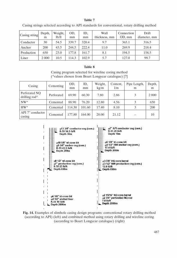
4.4. Casing selection
Based on the results of the design calculations made in section 3, two examplesof casing set were selected according to API standards (Tab. 7) and Diamond Core Drill-ing Manufacturers Association (DCDMA) coring standards (Tab. 8). Schematic drawingof both casing programs is presented in Figure 14.
487
Table 7
Casing strings selected according to API standards for conventional, rotary drilling method
Table 8
Casing program selected for wireline coring method(*values chosen from Boart Longyear catalogue) [7]
Fig. 14. Examples of slimhole casing design programs: conventional rotary drilling method(according to API) (left) and combined method using rotary drilling and wireline coring
(according to Boart Longyear catalogue) (right)
Casing string Depth, m
Weight, lb/ft
OD, mm
ID, mm
Wall thickness, mm
Connection OD, mm
Drift diameter, mm
Conductor 30 54.5 339.7 320.4 9.7 365.1 316.5
Anchor 200 43.5 244.5 222.4 11.0 269.9 218.4
Production 650 23.0 177.8 161.7 8.1 194.5 158.5
Liner 2 000 10.5 114.3 102.9 5.7 127.0 99.7
Casing Cementing OD, mm
ID, mm
Weight, kg/m
Content, l/m
Pipe Length, m
Depth, m
Perforated NQ drilling rod*
Perforated 69.90 60.30 7.80 2.86 3 2 000
NW* Cemented 88.90 76.20 12.80 4.56 3 650
HW* Cemented 114.30 101.60 17.40 8.10 3 200
API 7” conductor casing
Cemented 177.80 164.00 20.00 21.12 – 10
488
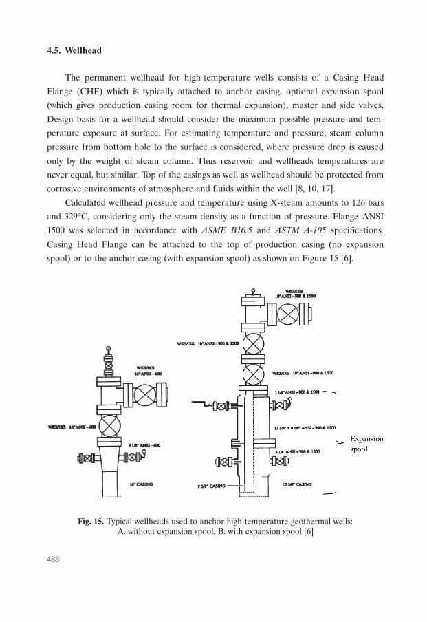
4.5. Wellhead
The permanent wellhead for high-temperature wells consists of a Casing Head
Flange (CHF) which is typically attached to anchor casing, optional expansion spool
(which gives production casing room for thermal expansion), master and side valves.
Design basis for a wellhead should consider the maximum possible pressure and tem-
perature exposure at surface. For estimating temperature and pressure, steam column
pressure from bottom hole to the surface is considered, where pressure drop is caused
only by the weight of steam column. Thus reservoir and wellheads temperatures are
never equal, but similar. Top of the casings as well as wellhead should be protected from
corrosive environments of atmosphere and fluids within the well [8, 10, 17].
Calculated wellhead pressure and temperature using X-steam amounts to 126 bars
and 329°C, considering only the steam density as a function of pressure. Flange ANSI
1500 was selected in accordance with ASME B16.5 and ASTM A-105 specifications.
Casing Head Flange can be attached to the top of production casing (no expansion
spool) or to the anchor casing (with expansion spool) as shown on Figure 15 [6].
Fig. 15. Typical wellheads used to anchor high-temperature geothermal wells:A. without expansion spool, B. with expansion spool [6]
489
5. CONCLUSIONS
1. Slim wells are drilled with much lower costs than regular or large size geothermal
wells and with less environmental impact. Such wells provide equally informative
geological and reservoir engineering data as large size holes. Slimhole technology
allows drilling three to four wells in cost of one large size well for better assessment
of geothermal reservoir and with lower economic rick.
2. Depending on geological characteristic of area different methods of slimhole drill-
ing can be used. Wireline coring method has lower environmental impact and
drilling costs (with core barrel can be used as casing string), than conventional rota-
ry drilling method. On the other hand, rotary method provides faster drilling
and there are no depth limitations. Casing loads calculations for rotary method are
already well described by API standards, where there are no well-established
methods of calculating casing loads in wireline casing strings.
3. This study shows that the casing setting depth methods assuming steam filled well or
two-phase flow, which is commonly used in geothermal industry, gives comparable
results to the Boiling Point Depth curve. Actual casing setting depths are usually
based on minimum temperature (e.g. 210°C for high-temperature wells) at the pro-
duction casing shoe and may be considerably deeper than the minimum crite-
ria. Then the minimum casing depths of the anchor and surface casings need to be
reassessed.
4. Properties of casing, found in API standards, do not include minimum strength
requirements at elevated temperatures. As yield strength of the casing material de-
creases significantly at higher temperatures, temperature correction factor from
New Zealand Standard 2015 should be used for geothermal well designs.
5. Internal pressure (burst) is the highest at the surface, while collapse pressure is
the highest at casing shoe. Tensile loads depend mostly on the weight of the casing.
Quite shallow setting of cemented casing strings in slimhole well results in high burst
loads and low collapse loads. Tensile loads are minor, due to the lightweight of the
casing. For exploratory geothermal wells, casing should be of low grade steel (K-55)
and casing joint should be of API Standard Buttpress.
6. While estimating the wellhead’s temperature and pressure, isenthalpic steam
column from bottom hole to the surface should considered, where pressure drop
is caused only by vapour density. Permanent wellhead can be installed either on
the top of the anchor or the production casing.
490
7. During drilling for geothermal resources, one can encounter high-temperature
formations containing corrosive fluids. As slotted liner is the deepest casing string
and it is installed in the open hole, it can experience severe corrosion, which can
radiate to shallower casing. Thus, revision of the slotted liner material (e.g. fiber
glass) should be considered in the future casing designs for slimhole wells.
Acknowledgements
Many thanks to staff of Keilir Institute of Technology, Dr. Sverrir Guðmundsson,
Ms. Krista Hannesdóttir and Mr. Guðmundur Borgţórsson for constant support and advice
during Michal Kruszewski’s stay in Iceland.
REFERENCES
[1] Friðleifsson G.O., Elders W.A., Zierenberg R., Weisenberger T.B., Harðarson