24
Michelson Interferometer Kit Assembly & User’s Guide INDUSTRIAL FIBER OPTICS Model Numbers: 45-940 45-941 45-942 45-943 45-944
MichelsonInterferometer Kit
Assembly & User’s Guide
IndustrIal FIber OptIcs
Model Numbers: 45-940 45-941 45-942 45-943 45-944

*
Copyright © 2010 Previous Printing © 2008
by Industrial Fiber Optics, Inc.Revision - E
Printed in the United States of America
* * *
All rights reserved. No part of this publication may be reproduced,stored in a retrieval system, or transmitted in any form or by any means
(electronic, mechanical, photocopying, recording, or otherwise)without prior written permission from Industrial Fiber Optics.
* * * * *

– i –
IntroductionThe Michelson Interferometer Kit 45-942 is a set of optical components and
mountings that assist in a rapid assembly of a Michelson Interferometer. This is a well-known device for splitting a beam of monochromatic light into two parts. These two parts travel along different optical paths and then merge to produce interference fringes on a screen.
The interference fringes shift noticeably whenever there is an almost unper-ceivable movement of one of the optical components. They will also shift when the effective length of one optical path changes slightly with respect to that of the second. These shifts make it possible to measure changes of a medium’s index of refraction and microscopic movements of components.
Before the advent of a laser with a visible beam, the alignment of interferom-eter components was very difficult to achieve under ordinary laboratory condi-tions. Now, using the bright beam of an inexpensive Industrial Fiber Optics laser pointer, alignment can be rapidly achieved and demonstrated.
As soon as you receive this kit inspect it and the shipping container for damage. If any damage is found, immediately refer to the section of this manual entitled “Shipment Damage Claims.“
Industrial Fiber Optics makes every effort to incorporate state-of-the-art tech-nology, highest quality, and dependability in its products. We constantly explore new ideas and products to best serve the rapidly expanding needs of industry and education. We encourage comments that you may have about our products, and we welcome the opportunity to discuss new ideas that may better serve your needs. For more information about our company and products refer to http//www.i-fiberoptics.com on the Worldwide Web.
Thank you for selecting this Industrial Fiber Optics product. We hope it meets your expectations and provides many hours of productive activity.
Sincerely,
The Staff at Industrial Fiber Optics

– ii –

– iii –
TABLE OF CONTENTSIntroduction……………………….................……....…………..…… i
SAFETY PRECAUTIONS…………................…......………...…….. 1
KIT CONFIGURATIONS……………….....................………...……. 1
Base Configuration..................................................................... 1
Optional Configurations.............................................................. 1
PARTS NOT INCLUDED IN KIT..................................................... 1
PARTS LIST FOR KIT 45-942......................................................... 2
PARTS LIST FOR OPTIONALCONFIGURATION.......................... 3
PREPARATION OF COMPONENTS............................................... 4
ASSEMBLY AND ALIGNMENT....................................................... 6
EXPERIMENT #1............................................................................. 9
Measuring the Coefficient of Linear Expansion of a Metal.......... 9
PROCEDURE................................................................................... 10
EXPERIMENT #2............................................................................ 12
Michelson Interferometer as a Seismograph............................. 12
EXPERIMENT #3............................................................................ 13
Sensing a Change in the Index of Refraction............................. 13
EXPERIMENT #4............................................................................. 14
Index of Refraction for a Gas...................................................... 14
CLEANING AND STORAGE............................................................ 15
SERVICE AND MAINTENANCE...................................................... 16
WARRANTY..................................................................................... 16
SHIPMENT DAMAGE CLAIMS....................................................... 17
– iv –
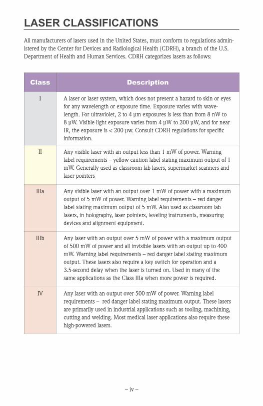
LASER CLASSIFICATIONSAll manufacturers of lasers used in the United States, must conform to regulations admin-istered by the Center for Devices and Radiological Health (CDRH), a branch of the U.S. Department of Health and Human Services. CDRH categorizes lasers as follows:
Class Description
I A laser or laser system, which does not present a hazard to skin or eyes for any wavelength or exposure time. Exposure varies with wave-length. For ultraviolet, 2 to 4 µm exposures is less than from 8 nW to 8 µW. Visible light exposure varies from 4 µW to 200 µW, and for near IR, the exposure is < 200 µw. Consult CDRH regulations for specific information.
II Any visible laser with an output less than 1 mW of power. Warning label requirements – yellow caution label stating maximum output of 1 mW. Generally used as classroom lab lasers, supermarket scanners and laser pointers
IIIa Any visible laser with an output over 1 mW of power with a maximum output of 5 mW of power. Warning label requirements – red danger label stating maximum output of 5 mW. Also used as classroom lab lasers, in holography, laser pointers, leveling instruments, measuring devices and alignment equipment.
IIIb Any laser with an output over 5 mW of power with a maximum output of 500 mW of power and all invisible lasers with an output up to 400 mW. Warning label requirements – red danger label stating maximum output. These lasers also require a key switch for operation and a 3.5-second delay when the laser is turned on. Used in many of the same applications as the Class IIIa when more power is required.
IV Any laser with an output over 500 mW of power. Warning label requirements – red danger label stating maximum output. These lasers are primarily used in industrial applications such as tooling, machining, cutting and welding. Most medical laser applications also require these high-powered lasers.

– 1 –
SAFETY PRECAUTIONS The output power of Industrial Fiber Optics laser pointers is low, but because the beam is intense and concentrated it should be treated with respect. As a safety precaution, the switch that activates the laser automatically turns the laser off whenever the operator releases pressure. Do not use a mechanical means to hold the switch in the ON position until you are sure that the beam will be confined and that there is no chance of it entering anyone’s eyes.
KIT CONFIGURATIONSBase Configuration
Interferometer Kit 45-942 contains a complete set of parts that is needed to assemble a basic Michelson Interferometer. To perform experiments an Industrial Fiber Optics laser pointer or equivalent is required but not included.
Optional Configurations
Interferometer Kit 45-940 contains all of the components in kit 45-942. In addition, Indus-trial Fiber Optics Laser Pointer IF-560 (650 nm, Class IIIa) is also included.
Interferometer Kit 45-941 contains all of the components in kit 45-942. In addition, Indus-trial Fiber Optics Laser Pointer IF-564 (635 nm, Class IIIa) is also included.
Interferometer Kit 45-943 contains all of the components in kit 45-942. In addition, Indus-
trial Fiber Optics Laser Pointer IF-563 (650 nm, Class II) is also included.
Interferometer Kit 45-944 contains all of the components in kit 45-942. In addition, Indus-trial Fiber Optics Laser Pointer IF-566 (532 nm, Class II) is also included.
Parts NOT Included In Kits
Screen (glossy white paper); Metal rod or tubing; Screw(s) or bolt(s); Clamp; Ring stand; Gas chamber; Vacuum pump; Soldering iron

– 2 –
Parts List for Kit 45-942
Qty Catalog No. Item, Description and Use
1 45-468 Fitted case.
1 120101 Instruction manual.
1 45-648 Optical platform 32.4 cm x 23.6 cm x 0.64 cm. Steel base provides a work surface to magnetically mount the laser holder and the U-shaped carriers.
6 45-649 U-shaped carriers. Used to position the components on the optical platform.
2 45-650 L-shaped carriers. Used to position the front-surface mirrors on the U-shaped carriers.
2 45-660 Magnetic strips. 15 cm long strips with adhesive backs. May be cut with scissors or scored with a knife and broken to provide magnetic connections among the components.
1 45-652 Short focal-length lens. Lens mounted on 6 cm square steel plate. Used to expand the interference patterns for viewing on the screen.
1 45-728 Beam splitter. Used to partially reflect and transmit the laser beam in two directions.
2 45-646 Front surface mirrors. Used to reflect and redirect laser beam.
1 45-251 Laser pointer holder. Holds laser pointer and magnetically attaches to base using two u-shaped carriers (45-649).
– 3 –
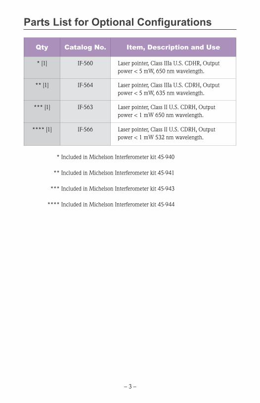
Parts List for Optional Configurations
Qty Catalog No. Item, Description and Use
* [1] IF-560 Laser pointer, Class IIIa U.S. CDHR, Output power < 5 mW, 650 nm wavelength.
** [1] IF-564 Laser pointer, Class IIIa U.S. CDRH, Output power < 5 mW, 635 nm wavelength.
*** [1] IF-563 Laser pointer, Class II U.S. CDRH, Output power < 1 mW 650 nm wavelength.
**** [1] IF-566 Laser pointer, Class II U.S. CDRH, Output power < 1 mW 532 nm wavelength.
* Included in Michelson Interferometer kit 45-940 ** Included in Michelson Interferometer kit 45-941 *** Included in Michelson Interferometer kit 45-943
**** Included in Michelson Interferometer kit 45-944

– 4 –
Preparation of Components For UseAfter checking that the interferometer kit is complete, you will complete the assembly of this by cutting the magnetic strip to size, peel off the adhesive backing and affix the strips to the appropriate parts. Refer to the instructions below.
A. Beam Splitter: Affix two narrow pieces of magnetic tape (approximately 10 mm [3/8 inch] lengths of the 25.4 mm [1 inch] wide tape) near ends of the beam splitter. Be careful to keep the surface of the beam splitter clean and free of fingerprints.
Fig.1. Beam splitter and the correctposition of magnetic tape
B. Front Surface Mirrors: Affix magnetic tape over the entire back surface of each mirror. Carefully peel off the protective blue covering from the mirrors front surface. Once the covering is removed, avoid touching the front surface of the mirror.
Fig. 2. Front surface mirror
C. U-Shaped Carriers: Affix two pieces of magnetic tape to the bottom of the carrier and additional pieces along the upright portions. The tape pieces should measure approximately 10 mm x 25.4 mm.
Fig. 3. U-Shaped carrier with the four locationswhere magnetic tape is installed

– 5 –
D. Laser pointer holder: Insert an Industrial Fiber Optics laser pointer into the center of the laser pointer holder as shown in Fig. 4. Tighten the six nylon screws around the laser pointer body to hold it securely in place. Be sure that the brass thumbscrew of the holder contacts the pushbutton switch of the pointer. Don’t thread the thumbscrew any further than required to contact the switch since it will activate the laser.
Fig. 4. Laser pointer holder and laser supported by two U-carriers
Fig. 5. Thumbscrew orientation
2004.eps
1690.eps
Note: It is not necessary to affix any magnetic tape to the L-shaped carriers or the square steel plate that holds the short focal-length lens.

– 6 –
Assembly and AlignmentMount all of the interferometer components (except a screen for viewing fringe patterns) on the base platform. See instructions on the following page.
A. Optical Platform B. Laser Pointer C. First Front Surface Mirror D. Second Front Surface Mirror E. Beam Splitter F. Diverging Lens G. Screen
Fig. 6 Schematic diagram of the interferometercomponents mounted on the platform

– 7 –
Insert an Industrial Fiber Optics laser pointer in the holder and mount it on the 1. optical platform. With the laser operating, check that the beam is horizontal.
Magnetically mount a front 2. surface mirror on L and U-shaped carriers Fig. 7. Attach it to the optical platform at location C. Adjust the mirror so the laser beam strikes its center and the reflected beam is returned to the laser. However, be careful that the beam does not actually re-enter the laser aperture.
Attach the beam splitter to a 3. U-shaped carrier and mount it to the platform at a 45-degree angle to the laser beam Fig. 6. Adjust its height so part of the beam will be transmitted through the splitter and the rest reflected at an angle of 90 degrees. Adjust its horizontal alignment so that the internal reflection inside the beam splitter is blocked by the black tape Fig. 8.
Place a screen, consisting of glossy white paper in the position shown in Fig. 6. A 4. bright red spot should appear on the screen, the returning beam reflected off the beam splitter.
Mount a second mirror on L and U-shaped carriers on the platform at location D. 5. Adjust the mirror so the split portion of the beam is reflected back through the beam splitter, producing a second red dot on the screen.
BeamSplitter
Masking Tape
MagneticTape
MagneticTape
2000.eps
Fig. 8. Blocking internal reflections inside the beam splitter.
Fig. 7. Diagram of front surface mirror assembly
Note: For optimum performance, the two mirrors should be equidistant from the center of the beam splitter. You may observe several additional faint red dots caused by unavoidable internal reflections of beams passing through the beam splitter. These do not affect the operation of the interferometer and can be ignored.
– 8 –
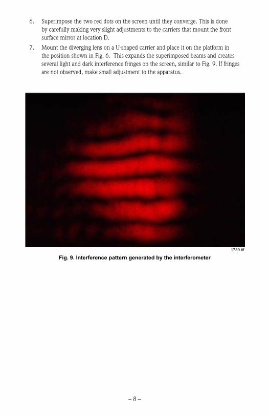
Superimpose the two red dots on the screen until they converge. This is done 6. by carefully making very slight adjustments to the carriers that mount the front surface mirror at location D.
7. Mount the diverging lens on a U-shaped carrier and place it on the platform in the position shown in Fig. 6. This expands the superimposed beams and creates several light and dark interference fringes on the screen, similar to Fig. 9. If fringes are not observed, make small adjustment to the apparatus.
Fig. 9. Interference pattern generated by the interferometer
1739.tif
– 9 –
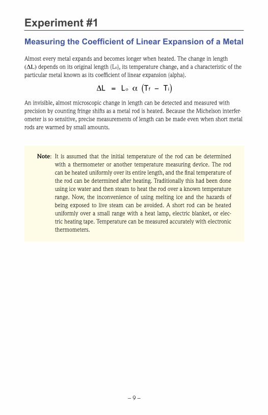
Experiment #1Measuring the Coefficient of Linear Expansion of a Metal
Almost every metal expands and becomes longer when heated. The change in length (ΔL) depends on its original length (Lo), its temperature change, and a characteristic of the particular metal known as its coefficient of linear expansion (alpha).
An invisible, almost microscopic change in length can be detected and measured with precision by counting fringe shifts as a metal rod is heated. Because the Michelson interfer-ometer is so sensitive, precise measurements of length can be made even when short metal rods are warmed by small amounts.
€
∆L = Lο α Tf − Ti( )
Note: It is assumed that the initial temperature of the rod can be determined with a thermometer or another temperature measuring device. The rod can be heated uniformly over its entire length, and the final temperature of the rod can be determined after heating. Traditionally this had been done using ice water and then steam to heat the rod over a known temperature range. Now, the inconvenience of using melting ice and the hazards of being exposed to live steam can be avoided. A short rod can be heated uniformly over a small range with a heat lamp, electric blanket, or elec-tric heating tape. Temperature can be measured accurately with electronic thermometers.

– 10 –
ProcedureObtain copper, brass, aluminum and iron rods that are approximately 10 to 20 1. cm long and less than 0.5 cm in diameter. If rods are not available, metal tubing, long metal screws, or bolts may be substituted.
Using an adhesive or double-sided sticky tape, fasten a piece of front surface mir-2. ror over the end of the metal rod.
Clamp the rod to the ringstand and set up the interferometer as shown in Fig. 10.
Fig. 10. Diagram of interferometer setup for experiment #1
Note: It is important to have equal distances from the mirrors to the center of the beam splitter.

– 11 –
Once the mirrors have been adjusted for wide fringes on the screen, heat the 3. rod and observe that fringes move slowly across the screen. Remove the source of heat and observe that the direction of fringe movement is reversed as the rod cools.
To determine the rod’s coefficient of linear expansion: 4.
a) Measure the initial length of the rod (Lo) and its initial temperature (Ti) before heating.
b) Apply a source of heat uniformly across the entire length of the rod from the mirror end to the ringstand clamp.
c) As the temperature of the rod increases, record the final temperature (Ti) and the number of fringes that moved across a selected point on the screen. (Remember that the change in length (∆L) is equal to one-half the wavelength of the laser beam for each fringe). Substitute these values in the equation below and solve for alpha, the coefficient on linear expan-sion.
€
∆L = Lο α Tf − Ti( )

– 12 –
Experiment #2
The Michelson Interferometer as a Seismograph
As you assembled and aligned the interferometer you likely noticed how sensitive it is to vibration or the slightest movement of either mirror. The steel base provided as an optical platform for the interferometer is relatively sturdy and convenient, but it’s not intended as a substitute for a rigid vibration isolated optical lab table. It does serve to illustrate how the Michelson interferometer can be used as an ultra sensitive motion or vibration detector (seismograph).
As you observe the interference fringes, gently tap the lab table on which the platform rests. The vibration from the tap travels into the platform and displaces one or both mirrors causing the fringe pattern to move. When the vibration stops the fringe movement stabi-lizes to its original fixed pattern. The interferometer is so sensitive that even pushing on the relatively stiff steel platform causes movement of the fringes. This shows that stiffness is a relative term since even a slight pressure on a steel plate causes flex that can be displayed if the instrument is sensitive enough. Specialized optical tables are engineered to resist flex while still maintaining a relatively low weight and reasonable thickness.
Besides conducted vibration, the mirrors will also respond to sound carried through the air. While observing the fringes, whistle or speak loudly near either fixed mirror – you should see a significant fringe movement synchronized with the sound. Consider that one of the fixed mirrors could be mounted in a way so that it would behave as an ultra sensitive microphone.
Michelson interferometers require careful setup on a rigid vibration isolated platform so they only respond to the change we wish to measure. Once that’s established either mirror can be used as a stable “reference arm”, while the other is used to sense movement, vibration, etc. The result is an extraordinarily sensitive measurement system that can be put together with relatively low cost using modern laser technology.

– 13 –
Experiment #3
Sensing a Change in the Index of Refraction
The Michelson interferometer can also sense the change in a basic property of an optical material – the index of refraction. Plug in a soldering iron and let it reach full operating temperature. Turn on the laser pointer in the interferometer setup and let it stabilize until the fringe pattern is static. Carefully bring the soldering iron just below the laser beam striking either fixed mirror and notice the effect on the fringe pattern.
Heat from the soldering iron lowers the air density around it, which also lowers the refractive index. The velocity of the laser beam increases as it passes through the reduced air density effectively changing the relative path length between the split beams. This qualitative demonstration shows how sensitive the interferometer is to minute changes in the speed of light as it passes through various media. In a more precise physical setup it’s possible to quantify the amount of change and use it to determine the refractive index for various gases.

– 14 –
Experiment #4
Index of Refraction for a Gas
Arrange the Michelson interferometer with a front surface mirror at one of the arms and a gas chamber mirror combination at the other arm. Use a vacuum pump to evacuate the air in the chamber and then allow air or other gas to return slowly. Air reduces the speed of light and effectively increases the beam path in the gas chamber. Each time the path increases by one wavelength, a fringe can be seen to shift on the screen. The approximate index of refraction for air (or any other gas in the chamber) can be determined by using the relationship:
Where: = index of refraction
= length of chamber
= number of fringes counted while transitioning from vacuum to atmo-spheric pressure
= wavelength of laser
A more precise formula would include temperature and the exact pressure differential between an evacuated chamber and true atmospheric pressure.
€
λ
€
m
€
L
€
n€
n = 2L + m λ( ) / 2L

– 15 –
Cleaning and Storage Whenever necessary, clean the mirrors, beam splitter, and lens with a dilute mixture of liquid detergent and lukewarm water – DO NOT USE ALCOHOL ON ALUMINIZED MIRROR SURFACES. NEVER USE ABRASIVE CLEANERS.
Soak a cotton ball in the detergent mixture and gently wipe the surface of the optical components. You may immerse mirrors in the mixture container but avoid doing that with lenses unless they are single component and not a cemented compound lens. Rinse the optics under running tap water to wash away the detergent mixture. If possible use distilled or purified water for a final rinse. Blow any remaining beads of water off with canned compressed air or a similar dusting product. Use a dry cotton ball to gently remove any remaining residue – DO NOT APPLY PRESSURE, SIMPLY WIPE THE SURFACE.
To help protect the component parts and keep them clean and dust free, return all loose items to their original positions in the fitted case after each use.

– 16 –
Service and MaintenancePeriodic operation and service of Industrial Fiber Optics’ laser pointers are not required. The batteries will periodically need to be replaced, refer to the instruction pamphlet included with the laser pointer for directions. The warranty will be voided if entry has been made to the pointer housing other than for replacement of batteries.
WarrantyThis kit was carefully inspected before leaving the factory. It is warranted for workmanship and completeness for 90 days. If any components were damaged in shipping, Industrial Fiber Optics will replace them at its discretion.
If this kit contains a laser pointer, the pointer comes with a 90-day warranty.
If any parts become lost or damaged, replacements may be obtained from Industrial Fiber Optics. Refer to the parts list on Page 2 and of this manual or to our web site, www.i-fiberoptics.com for identification.
Industrial Fiber Optics recognizes that responsible service to its customers is the basis of our continued operation. We welcome and solicit your feedback about our products and how they might be modified to best suit your needs.

– 17 –
Shipment Damage ClaimsIf damage to an Industrial Fiber Optics product should occur during shipping, it is impera-tive that it be reported immediately, both to the carrier and the distributor or salesperson from whom the item was purchased. DO NOT CONTACT INDUSTRIAL FIBER OPTICS.Time is of the essence because damage claims submitted more than five days after delivery may not be honored. If shipping damage has occurred during shipment, please do the fol-lowing:
Make a note of the carrier company; the name of the carrier employee; the date, •and the time of the delivery.
Keep all packing material. •
In writing, describe the nature of damage to the product.•
Notify the carrier immediately of any damaged product.•
Notify the distributor from whom the purchase was made.•
------------------------------

12 0101
Rules for Laser Safety• Lasers produce a very intense beam of light. Treat them with respect. Most
educational lasers have an output of less than 3 milliwatts, and will not harm the skin.
• Never look into the laser aperture while the laser is turned on! PERMANENT EYE DAMAGE COULD RESULT.
• Never stare into the oncoming beam. Never use magnifiers (such as binoculars or telescopes) to look at the beam as it travels – or when it strikes a surface.
• Never point a laser at anyone’s eyes or face, no matter how far away they are.
• When using a laser in the classroom or laboratory, always use a beam stop, or project the beam to areas, which people won’t enter or pass through.
• Never leave a laser unattended while it is turned on – and always unplug it when it’s not actually being used.
• Remove all shiny objects from the area in which you will be working. This includes rings, watches, metal bands, tools, and glass. Reflections from the beam can be nearly as intense as the beam itself.
• Never disassemble or try to adjust the laser’s internal components. Electric shock could result.


