8. Hydraulic Capacity Certification- New Crossing 15
9. References and Resources 16
10. Cross Section Guidelines 17
MDEQ Hydraulic Report Guidelines Page 3 Revised February 14, 2013
Introduction A hydraulic analysis is required on streams/drains with a drainage area of 2 square miles or more when a proposed project may cause an increase in existing floodplain elevations. When it is not definitive as to whether a project will or will not cause an increase, then an analysis should be provided even if to show that there was no increase. When a hydraulic analysis is required, a $1500 hydraulic review fee (for each analysis) should be submitted in addition to the normal application fee. The hydraulic analysis should compare the existing floodplain energy grade line elevations with the proposed floodplain energy grade line elevations for a range of discharges up to and including the 100-year flood frequency discharge. Flood frequency discharges for watercourses with a drainage area of 2 square miles or more may be requested free of charge from the MDEQ (page 10). If the proposed project causes an increase in the existing floodplain elevations then an engineer licensed in Michigan must certify that the increase is non-harmful. Harmful interference is defined as causing an increase stage or change in the direction of flow that causes, or is likely to cause: damage to property; a threat to life; pollution, impairment, or destruction of water or other natural resources. A copy of the damage assessment guidelines and certification language is found on pages 11-15. If the project causes an increase in flood elevations that are above the stream banks and occurs outside of the applicant’s property, then affected property owner statements (pages 13-14) need to be sent by certified mail to all the affected property owners, or the project must be redesigned. A project that is determined by the MDEQ to cause a harmful interference cannot be permitted. These guidelines are designed to assist those submitting a hydraulic analysis and report for state permitting under the State’s Floodplain Regulatory Authority found in Part 31, Water Resources Protection, of the Natural Resources and Environmental Protection Act, 1994 PA 451, as amended, for state concurrence of a Letter of Map Revision, or any other modeling that is submitted for review. The guidelines are intended for professionals familiar with floodplain management and hydraulic modeling. They do not provide instructions for using hydraulic modeling programs.
MDEQ Hydraulic Report Guidelines Page 4 Revised February 14, 2013
Hydraulic Analysis and Report Submittal Requirements The following information must be included as part of the submittal of a hydraulic report to the Michigan Department of Environmental Quality (MDEQ). A $1,500 hydraulic review fee in addition to the normal application fee. A Hydraulic Report (including supporting data, plans, and other documentation) prepared
and sealed by an engineer licensed in Michigan. For projects where there is an increase in the energy grade (an increase of 0.005 feet or
greater) for the proposed versus the existing conditions the following requirements apply:
o If there is any increase in the energy grade between existing and proposed conditions, the engineer must certify that the increase does not interfere harmfully with the discharge or stage characteristics of the stream.
o If there is any increase in energy grade between existing and proposed conditions that extends beyond the banks of the main channel and occurs outside of the applicant’s property, affected property owner statements need to be sent by certified mail to all the affected property owners (or the project must be redesigned to eliminate the increase).
o A project that causes a harmful interference cannot be permitted.
For projects located within a detailed floodplain study area mapped by the Federal Emergency Management Agency (FEMA), the following modeling may be required by the local community and/or FEMA in addition to the existing and proposed conditions:
o Base Conditions referenced (from the FEMA Flood Insurance Study) o Duplicate Effective (base condition plus updated/corrected geometry and flow
data) o Corrected Effective (duplicate effective plus the proposed conditions) o Additional flood profiles o Floodplain and/or floodway delineations o Projects that change the location elevation of a floodplain map produced by the
Federal Emergency Management Agency (FEMA) will generally require the applicant to obtain a conditional letter of map amendment from FEMA.
MDEQ Hydraulic Report Guidelines Page 5 Revised February 14, 2013
When is a Hydraulic Analysis Needed? This is a general list of when a hydraulic analysis is needed for review under the State’s Floodplain Regulatory Authority found in Part 31, Water Resources Protection, of the Natural Resources and Environmental Protection Act, 1994 PA 451, as amended. It does not indicate when a hydraulic analysis may be required by other agencies such as the county drain commissioner or the local community.
A hydraulic analysis is required for the following:
1. Filling or construction in the floodway that exceeds 1% of the cross sectional area of the 100 year floodway unless the construction is directly in-line, adjacent to and on the downstream side of an existing obstruction.
2. Stream relocation 3. Changing the FEMA floodway line 4. Culvert or bridge replacement projects that have the following characteristics (with all
other items remaining equal) : a. An increase in road grade more than the addition of a new wearing course
(assumed to be 4 inches or less) unless the existing road grade is above the 100 year floodplain elevation
b. A reduction in end area. c. An increase in the Manning’s roughness coefficient (ie. – going from a concrete
to metal culvert) d. A reduction in the efficiency of the entrance condition (ie.- going from a headwall
condition to a projecting or mitered end section. e. An extension onto an existing structure that exceeds 24 feet. f. A new culvert/bridge that is longer/wider than the existing structure g. A change in slope
A hydraulic analysis is not needed for the following:
1. If the stream/drain has a drainage area of less than 2 square miles. 2. If a project meets a minor project category found in Part 31, 3. Outside of a mapped floodway if a detailed map exists. 4. Encroachments representing 1% or less of the total 100-year floodway cross sectional
area. The 1% must be an equal and opposite encroachment; assume an equal encroachment on both sides of the river to calculate the percentage.
5. Culvert or bridge replacement where the size is increased such that there is a net increase in end area opening below the 100-year floodplain elevation with all other hydraulic factors remaining the same- ie same culvert length/bridge width, same or improved roughness condition, same or improved entrance conditions, same road grade unless the existing road grade is above the 100 year floodplain elevation, same slope.
MDEQ Hydraulic Report Guidelines Page 6 Revised February 14, 2013
6. A temporary crossing that is in place for 14 days or less where there is minimal blockage. Minimal blockage would be defined as having the top of the blockage no higher than 2 feet above the ordinary highwater mark. This type of work should be done during low flow conditions with the impounded water being pumped or culverted around the project site so as to maintain flow to the channel downstream of the work area.
7. Part width blockage of a stream where the blockage is ½ of the stream width or less, extends no more than 2 feet above the ordinary high water mark and the work is completed in 14 days or less.
8. For the installation of temporary sheet piling around bridge abutments/piers where the sheet piling is used to isolate the construction activity from the stream flow (ie allow work to occur in the dry.
9. A temporary bridge that is not more than 24 feet in width and that matches or exceeds and is directly adjacent to upstream bridge crossing.
10. A temporary culvert that is not more than 24 feet in length and that matches or exceeds and is directly adjacent to the upstream culvert crossing.
11. Removal of a dam except in a mapped floodplain area where it would be a benefit to the local community to show a lower 100-year floodplain elevation and where no grade control structures (cross vanes, rock ramps, J hooks, weirs) are being added.
12. Fish habitat structures that meet the minor project category under Part 301 and the following:
a. The width of the in stream structure shall not exceed 10% of the stream width. b. Fish habitat structures shall not be closer than 100 feet of each other. c. Structures that deflect flow from the channel bank shall note extend into the
stream more than 25% of the width of the stream. These structures shall not re-direct flow so as to cause erosion of the opposite bank.
d. Solid structures that extend from the water surface to the stream bottom shall have a deflection angle of 25 degrees or less.
Some projects may or may not require a hydraulic analysis. (Contact the district floodplain engineer to discuss)
1. Dam removal projects where grade control structures (cross vanes, rock ramps, J hooks, weirs) are being added particularly downstream of the existing dam.
2. J-hooks, weir, and cross vanes projects. When in doubt on other types of projects please contact your district floodplain engineer.
MDEQ Hydraulic Report Guidelines Page 7 Revised February 14, 2013
The Hydraulic Report The Hydraulic Report should provide an analysis of the proposed project compared to the existing conditions up to and including the 100-year frequency flood profile and the floodway/floodplain. The report should contain the following information. Introduction
Preparers name, company name, telephone number, and email. Describe the watercourse and location of investigation. Describe for whom the report is being prepared. Describe the name and type of project. Describe the scope of investigation including the alternatives analyzed and
evaluated. Describe the scope of the analysis (such as the absence of a floodway delineation
which may not be necessary in every situation such as a culvert analysis where there is no FEMA identified floodway).
Identify any existing studies or any history of work on the watercourse in the vicinity of the project including past flooding events.
Method of Analysis
Describe computational methods used to determine water surface profiles. Explain why the method was chosen and why it is appropriate for the project
evaluation. Explain any assumptions made in the application of the chosen method. Include references and provide a description and source of any computer
programs used. Hydraulic analysis computer programs such as HEC-RAS from the US Army Corp of Engineers or HY-8 from the Federal Highway Administration are preferred.
Use and reference MDEQ generated or approved discharges in the analysis. Explain any modeling iterations including the use of previous data (e.g. FEMA
study), the addition of updated/corrected geometry, etc. Upstream and Downstream Modeling Limits
Show the location of the modeling limits on the site development plan. Explain why the location was selected and the method used to determine the
starting water surface elevation. Include an analysis of calibration of the model(s) to existing FEMA Flood Insurance Study (FIS) profiles if they exist or other methods used to develop stable boundary downstream water surface conditions if no FIS is available.
The analysis must extend upstream to the point where any increase caused by the proposed project is dissipated.
Describe all modeling boundary conditions.
MDEQ Hydraulic Report Guidelines Page 8 Revised February 14, 2013
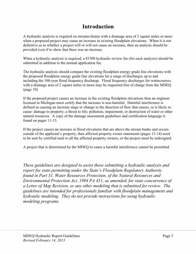
Variables, Coefficients, and Modeling Strategies
Discuss the following modeling variables and coefficients. Indicate references and explain all assumptions for the variables used in the model.
o Expansion and contraction o Orifice o Weir discharge o Friction o Include any other variables and coefficients that may apply to your model.
Provide photographs of present conditions and any other supporting information to justify values selected for existing and/or proposed conditions.
Describe the use of ineffective flow areas and/or blocked obstructions. Describe and provide supporting justification for the bridge/culvert modeling
options used. When a floodway is defined as part of the analysis, describe and provide
supporting justification of the floodway delineation method. For encroachments located in the floodway, equal and opposite encroachment into
the floodway must be modeled in the proposed conditions run. Assume an equal encroachment on both sides of the river to determine impacts.
Discussion
Provide a brief discussion and evaluation of the computations and analysis. Include a description of the present channel and floodway, the nature and
distribution of flow, and the proposed alterations and their resultant effect. Explain any unusual conditions that occur and all assumptions not previously
addressed that were part of the analysis. Conclusion
Provide a table comparing existing and proposed water surface elevations and energy grade lines for flood flows up to and including the 100-year flood flow.
Evaluate the effects of the proposed conditions on the watercourse, floodplain, and floodway (including upstream and, where appropriate, downstream effects).
MDEQ Hydraulic Report Guidelines Page 9 Revised February 14, 2013
APPENDIX/SUPPORTING DOCUMENTS A digital copy of the modeling runs for existing and proposed conditions. Each run
should be labeled appropriately. Extraneous runs should not be included. A profile sheet showing the channel inverts, water surface and energy grade line for both
existing and proposed conditions. A print out from a computer modeling program is not sufficient plan data.
A site development plan for existing and proposed conditions o A scaled plan view drawing o Location of all cross-sections used in the analysis o Flood Insurance Rate Map and flood profile (if available) o Existing and proposed topography o Property boundaries o Floodway delineation o Floodway alterations o Proposed floodway obstruction and property boundaries o River channel o Fill, excavation and grading o Existing and proposed bridges and culverts. Include the profiles of the road grade
along its highest points. (The information provided should be sufficient to analyze the crossings).
o The elevation datum used Note: The dimensions and work depicted in the model must match the permit plans and information in the application for permit.
Cross sections showing existing conditions and the proposed alterations. Cross sections should include the following information.
o Channel limits (the channel limits can be defined by the ordinary high water mark of the watercourse)
o Floodway limits o Floodplain boundary limits o Roughness coefficients o The coordinates of plotted points.
If the proposed project causes an increase in the energy grade elevation (greater than an increase of 0.005 feet or greater), you must provide a Damage Assessment Certificate (see example on page 12) to certify that the increase does not interfere harmfully with the discharge or stage characteristics of the stream. A harmful interference is defined as an increased stage or change in the discharge or direction of flow that causes or is likely to cause any of the following: damage to property; a threat to life; a threat to personal injury; pollution, impairment, or destruction of water or other natural resources.
If the proposed increase extends beyond the banks of the main channel and goes off the owner’s property then you must also send by certified mail the “Affected Property Owner Statements” to all upstream property owners impacted by the proposed increase. Verification that the letters were sent out by certified mail must be provided to the MDEQ.
A copy of the MDEQ discharge or discharge approval letter.
MDEQ Hydraulic Report Guidelines Page 10 Revised February 14, 2013
Requesting a Flood Discharge
Part 31 addresses flooding up to and including the 100-year (1% annual chance) flood. The Hydrologic Studies Program of the Water Resources Division calculates flood and low flow discharges, provides hydrologic engineering support for Nonpoint Source Pollution projects, and conducts other types of hydrologic analyses in support of the department's water-related programs.
You can request flood discharges by going to www.michigan.gov/hydrology and clicking “Request a flood or low flow discharge” or going to http://www.deq.state.mi.us/flow/index.shtml and clicking “Discharge Request Form.”
Discharges values are only valid for the person or entity that requested the discharge and are valid for one year after the date the response was sent.
In areas with a detailed FEMA Flood Insurance Study (FIS), the discharge from the FIS should be verified by the Hydrologic Studies Program.
If you have questions about requesting a flood discharge, you can contact the Hydrologic Studies Program at (517) 241-1210.
MDEQ Hydraulic Report Guidelines Page 11 Revised February 14, 2013
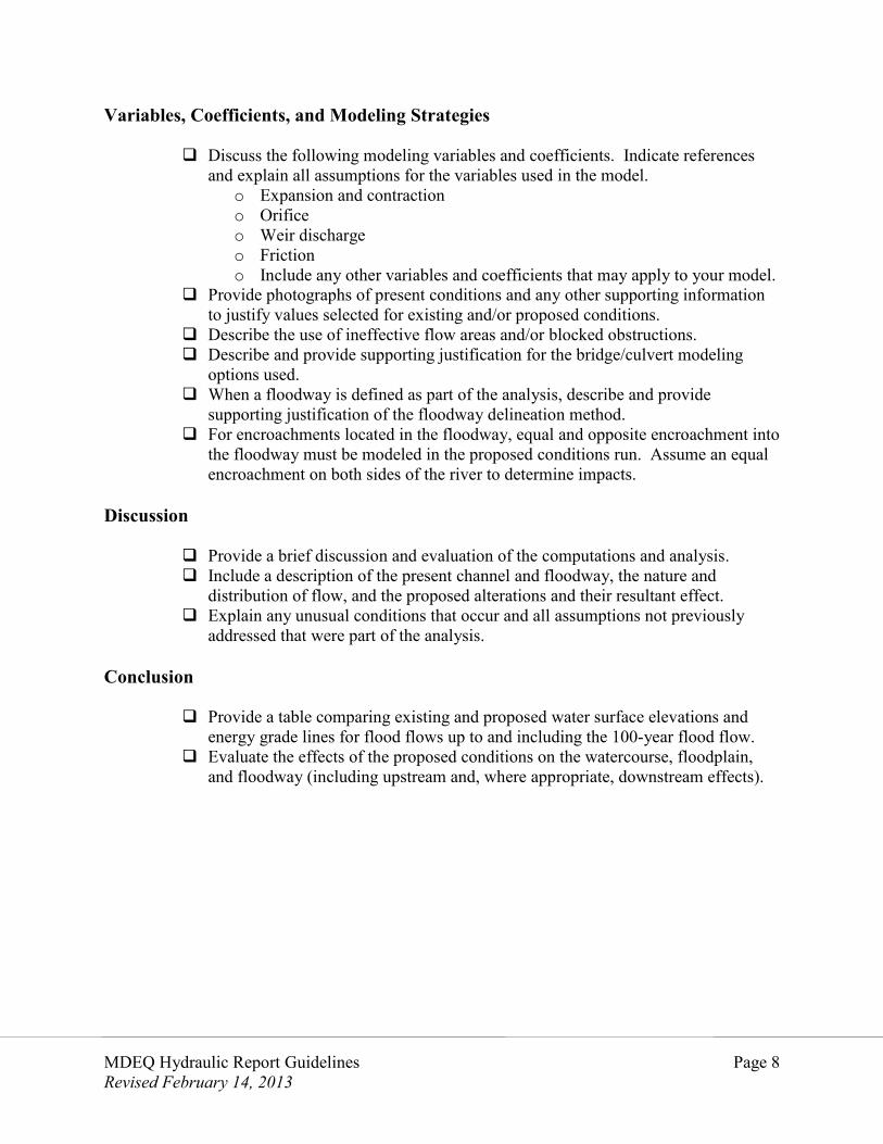
Damage Assessment Guidelines Proposed projects which cause an increase in flood stage (an increase of 0.005 feet or greater) that is not confined entirely within the limits of the applicant’s property require the following information to be submitted to the MDEQ. Submittal of this information does not guarantee that a permit can be issued. Property location map and a list of all property owners located within the area affected by
the increase in flood stage. A map showing the existing and proposed floodplain and all structures within and near
the affected area. For each structure, include the lowest adjacent ground elevation adjacent to the building (including deck stairs or supports), the lowest floor elevation, and the lowest sill elevation of a window or door of all structures located within the affected area.
A written damage assessment certification from a licensed engineer indicating that the
increase caused by the project will not cause a harmful interference and that the increase will not affect any insurable structures.
Notification shall be sent by certified mail to the affected property owners indicating the
extent of additional flooding and advising them to return the form to the MDEQ within 10 days. NOTE: Increases in flood stage will not be accepted for properties currently experiencing flood damage.
Copies of the letter(s) sent to the affected property owners and the certified mail receipts
must be submitted to the MDEQ Photographs of the affected properties and floodplain areas.
MDEQ Hydraulic Report Guidelines Page 12 Revised February 14, 2013
Damage Assessment Certification {Project Name} {Stream Name} {Town, Range, Section} {Community} {County} I, {Certifying Engineers Name & P.E. #}, do hereby certify that I have inspected the upstream adjoining properties and find that the reduction in hydraulic capacity and resulting {____} foot increase to upstream flood stages or diversion of flow will not cause a harmful interference or damage to adjacent structures or crop lands. Harmful interference is defined as an increased stage or change in the discharge or direction of flow that causes or is likely to cause any of the following: damage to property; a threat to life; a threat to personal injury; pollution, impairment, or destruction of water or other natural resources. (Affected Property Owner Statements must be sent to all property owners impacted by the proposed flood stage increase.)
MDEQ Hydraulic Report Guidelines Page 13 Revised February 14, 2013
Sample Affected Property Owner Statement Date: Department of Environmental Quality {District Floodplain Engineer Address} Dear _____________: SUBJECT: File {File Number} I/we (circle one) have been informed by the {Applicant/Agent} of a potential increased flood risk on my property. The increased risk would be caused by {describe project}. This project will cause an additional increase in the floodplain elevation at the upstream limits of the applicant’s property of {___} feet (elevation = {_______}) over existing floodplain conditions. I understand that this increased floodplain elevation could cause flooding on my property during a {100-year} flood which has a {1 percent chance} of occurring or being exceeded in any given year. I also understand that the proposed structure could increase flooding on my property during lesser flood frequencies. It is my opinion that this project will/will not (circle one) cause any of the following to my property: a) damage to property, b) threat to life, c) a threat to personal injury, d) pollution, impairment, or destruction of water or other natural resources. I can/cannot (circle one) recall any past flooding which has caused flood damage to my property. I can/cannot (circle one) recall that water has overtopped the existing road grade at the bridge/culvert location. Should additional information be required of me, I can be reached by writing {name} or telephone {telephone number}. Sincerely, {Property Owner(s) Signature(s)} {Address} {Phone} {Property Tax ID} (Form must be returned to the MDEQ within 10 days)
MDEQ Hydraulic Report Guidelines Page 14 Revised February 14, 2013
Date: Department of Environmental Quality Water Resources Division Transportation and Flood Hazard Unit PO Box 30458 Lansing, MI. 48909-7958 Dear _____________: SUBJECT: File ___________ I/we (circle one) have been informed by representatives of the ____________ County Road Commission of a potential increased flood risk on my property. The increased risk would be caused by replacing the existing ____ ft. span by ____ ft. rise (structure type) at the ___________ Road crossing of ____________ Creek with a _____ ft. span by _____ ft. rise (structure type). Installation of this structure will cause an additional increase in the floodplain elevation at the upstream limits of the road right-of-way of _____ feet (elevation =_______) over existing floodplain conditions. I understand that this increased floodplain elevation could cause flooding on my property during a {100-year} flood which has a {1 percent chance} of occurring or being exceeded in any given year. I also understand that the proposed structure could increase flooding on my property during lesser flood frequencies. It is my opinion that this project will/will not (circle one) cause any of the following to my property: a) damage to property, b) threat to life, c) a threat to personal injury, d) pollution, impairment, or destruction of water or other natural resources. I can/cannot (circle one) recall any past flooding which has caused flood damage to my property. I can/cannot (circle one) recall that water has overtopped the existing road grade at the bridge/culvert location. Should additional information be required of me, I can be reached by writing ________________ or telephone ____________. Sincerely, Property Owner(s) Signature(s) Address Phone Property Tax ID
(Form must be returned to the MDEQ within 10 days)
MDEQ Hydraulic Report Guidelines Page 15 Revised February 14, 2013
Hydraulic Capacity Certification (Replacement Crossing) Project Name Stream Name Town, Range, Section Township County I, Certifying Engineers Name & P.E. #, do hereby certify that the proposed _______ foot span by _______ foot rise {bridge/culvert} replacement including any change in road/driveway grade as shown on plans dated ____________________ is designed with an equal or greater hydraulic capacity when compared to existing conditions, and will not cause a harmful interference or damage to adjacent structures or croplands. Harmful interference is defined as an increased stage or change in the discharge or direction of flow that causes or is likely to cause any of the following: damage to property; a threat to life; a threat to personal injury; pollution, impairment, or destruction of water or other natural resources.
Hydraulic Capacity Certification (New Crossing) Project Name Stream Name Town, Range, Section Township County I, Certifying Engineers Name & P.E. #, do hereby certify that proposed _______ foot span by _______ foot rise {bridge/culvert} including the proposed road/driveway grade as shown on plans dated ___________________ is designed to pass the 100-year (1 % annual chance) flood without causing a harmful interference or damage to adjacent structures or croplands. Harmful interference is defined as an increased stage or change in the discharge or direction of flow that causes or is likely to cause any of the following: damage to property; a threat to life; a threat to personal injury; pollution, impairment, or destruction of water or other natural resources.
MDEQ Hydraulic Report Guidelines Page 16 Revised February 14, 2013
References and Resources
MDEQ Floodplain Management Websites:
www.michigan.gov/deqtransportationreview
or
www.michigan.gov/floodplainmanagement
Michigan Department of Transportation Drainage Manual
MDEQ Hydraulic Report Guidelines Page 17 Revised February 14, 2013
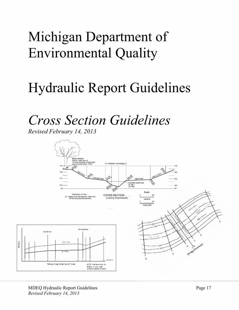
Michigan Department of Environmental Quality Hydraulic Report Guidelines Cross Section Guidelines Revised February 14, 2013
MDEQ Hydraulic Report Guidelines Page 18 Revised February 14, 2013
Cross Sections The computation of water surface profiles requires cross-sections at representative locations throughout the river reach. Cross sections provided as part of a hydraulic report should be generated from surveyed data. A printout from a hydraulic modeling program is not sufficient. General Requirements Cross sections location stations should increase from downstream to upstream. Each cross-section should be located on a topographic map of sufficient detail in order that the channel and overbank distances between sections can be measured accurately. Cross-sections should be taken perpendicular to the direction of the estimated center of mass of the flood flow. This direction, in some instances, may differ materially from that of the normal flow in the channel. Every effort should be made to obtain cross-sections that accurately represent the river geometry at all stages.
MDEQ Hydraulic Report Guidelines Page 19 Revised February 14, 2013
Cross Sections
Cross sections may not be uniform across the valley due to elevation or other geographic constraints. Bent or “dog leg” cross sections may be appropriate. Cross sections should not intersect.
Cross-sections should fully define transitional elements of a stream and floodplain such as; the cross-sectional area increasing or decreasing, channel or overbank roughness changes, or marked breaks in bottom slope. Each cross-section should be plotted at a reasonable scale with the left and right corresponding to that when viewed in the direction of flow (looking downstream). For each plotted point, the distance measured from a reference point on the left, and elevation should be shown. The water surface elevation and date taken should be included on each of the plotted cross-sections.
A profile of the channel bottom and water surface should be plotted from the cross-section data. The plotted distance between cross-sections is measured along the main channel during normal flow.
MDEQ Hydraulic Report Guidelines Page 20 Revised February 14, 2013
Cross Sections Cross Section Location and Spacing Locate a cross-section(s) at any property boundary and any city, township, county or other corporate boundaries. The distance between cross sections varies based on the stream slope, the floodplain width, and the uniformity of the channel. In general, cross section spacing of 500 feet is used when a river reach is fairly straight and uniform. Addition cross sections are required when there are changes in the features of the watercourse. The number of cross sections should be in proportion of the magnitude of the changes to the channel. Bends and meanders
Changes in channel slope
MDEQ Hydraulic Report Guidelines Page 21 Revised February 14, 2013
Cross Sections Changes in channel or floodplain geometry, such as encroachments, expansions, or
contractions.
Abrupt changes in cross-section or profile occurs, such as at bridges, dams or other manmade or natural restrictions, a sufficient number of cross-sections should be used to describe the change.
Changes in channel or overbank roughness
MDEQ Hydraulic Report Guidelines Page 22 Revised February 14, 2013
Cross Sections Bridges and Culvert Cross Sections Generally a minimum of six cross sections are required to model a bridge or culvert. However, more cross sections may be required to adequately represent site conditions in a model. At a minimum, cross sections should be located At the upstream and downstream bridge faces (not in road ditch line or on road shoulder)
At a location one bridge-span upstream
At a location four bridge-spans downstream
100-feet beyond the above cross-sections both upstream and downstream
Depending on where the analysis starts and the boundary conditions, there should be a
cross-section at least 500 feet downstream of the first bridge/culvert so that the model stabile at the point where the bridge/culvert will be analyzed.