5.0 POST INSTALLATION CHECK....................................................................................... 24
6.0 MICON 500L OPERATION .............................................................................................. 25 6.1 CONSOLE ASSESSING FOR PRICE CHANGING:MCIU ......................................................................25 6.2 READING TOTALIZERS ON A SINGLE TIER DISPENSER ..................................................................26
6.2.1 READING TOTALIZERS ON A SINGLE TIER DISPENSER .....................................................26 6.2.2 SETTING PRICES ON A SINGLE TIER DISPENSER...............................................................27
6.3 TWO TIER PRICE OPERATION.............................................................................................................28
6.3.1 TWO TIER OPTION INSTALLATION.........................................................................................28 6.3.2 SETTING PRICES ON A TWO TIER DISPENSER ...................................................................28 6.3.3 MAKING DISCOUNT PRICE SALES ON A TWO TIER DISPENSER.......................................29 6.3.4 READING TOTALIZERS ON A TWO TIER DISPENSER..........................................................29
11. COMMUNICATIONS INTERFACE CONNECTIONS FOR THE MICON 500LN (NORTH AMERICAN) ..........................................................................................................19
12. COMMUNICATIONS INTERFACE CONNECTIONS FOR THE MICON 500LE
9. HANDLE SHAFT ACTUATION FOR COUNTERCLOCKWISE ROTATION ........................10 10. PRICE SETTING USING THE MICON COMMUNICATOR ..................................................24 11. DISPLAY DOLLAR AND VOLUME TOTALS ........................................................................26 12. PRICE SETTING USING THE MICON COMMUNICATOR ..................................................27 13. READING TOTALIZERS.......................................................................................................30
14. THERMAL WELL LOCATION...............................................................................................34
Kraus Global Inc. 12/03 1 Micon 500L Publication Number 234AY09.INS R05 Installation Manual
1.0 IMPORTANT NOTICES All wiring must be installed in accordance with National and local electrical codes.
SUBSTITUTION OF COMPONENTS MAY IMPAIR INTRINSIC SAFETY. LA SUBSTITUTION DE COMPOSANTS PEUT COMPROMETTRE LA SÉCURITÉ INTRINSÈQUE.
When this unit is used in retail trade in Canada, Measurement Canada, an agency of Industry Canada, must be notified of the installation or service of this unit. This unit is subject to inspection upon installation and at such other times as the regulations may state. When ATCTM (automatic temperature compensation) is used, a thermal well must be provided. In addition to the thermal well and probe fitting, new installations will require two BC-256 labels reading "CORRECTED TO 15° C". These labels must be attached to each faceplate of the dispenser and be visible to the customer. These labels are provided with the MICON 500L, and additional labels are available upon request.
WARNING !
ATTENTION
!
AVERTISSEMENT
!
Kraus Global Inc. 12/03 2 Micon500L Publication Number 234AY09.INS R05 Installation Manual
MICON 500 is a registered trademark of Kraus Global Inc. ATC is a registered trademark of Kraus Global Inc.
Kraus Global Inc. 12/03 3 Micon 500L Publication Number 234AY09.INS R05 Installation Manual
2.0 PRE-INSTALLATION CHECK The MICON 500L is a computerized pumphead designed for use with liquid fuel (e.g., diesel, propane, butane) dispensers. After carefully unpacking the MICON 500L, inspect for shipping damage. Refer to the options label(s) on the MICON 500L shipping box(es) to ensure the MICON 500L is properly configured for the intended application. A preliminary electrical check should be performed as follows:
1. Observe position of the pump handle. The MICON 500L is normally shipped with the
actuator shaft in the battery OFF position: flat (beveled) surface on the end of the shaft facing DOWN. Current drain will be negligible, however, if unit shipped with battery ON.
2. Battery is ON whenever flat (beveled) side of shaft is facing any direction except DOWN. Battery should be ON with flat (beveled) side of shaft facing UP when handle OFF.
Prepare handle switch for a preliminary check by positioning shaft and coupler assembly in handle OFF position: a) Pull cotter pin. b) Rotate the coupler assembly to the desired “OFF” position. c) Rotate actuator shaft until the flat (beveled) side faces UP. d) Re-install cotter pin. The handle OFF coupler assembly will appear as in Figure 2. Coupler assembly may rest against stop pin #1 or stop pin #2, as long as flat (beveled) side of shaft faces UP when handle OFF.
battery OFF when flat (beveled) side of shaft facing DOWN
FIGURE 1 – BATTERY OFF ACTUATOR SHAFT POSITION
Kraus Global Inc. 12/03 Micon500L Publication Number 234AY09.INS R05 Installation Manual
4
2.0 PRE-INSTALLATION CHECK (CONT’D)
3. The MICON 500L digital display can be manually triggered to display configuration event counter data in the dollar display, model number in the volume display, and software version number in the price display, as shown in Figure 3. To do this:
Flip the handle switch rapidly ON, then OFF. The display will indicate as shown
in Figure 3. The event counter in the dollar display indicates the number of times the
settings have been changed with the INFO-PAC. The INFO-PAC is a hand-held, self-contained battery powered unit designed to monitor and program MICON electronic pumpheads.
FIGURE 2 – COUPLER ASSEMBLY HANDLE OFF POSITION
COUPLER ASSEMBLY
STOP PIN #1 STOP PIN #2
COTTER PIN
ACTUATOR SHAFT FLAT (BEVELED) SIDE UP IS HANDLE OFF (BATTERY ON) POSITION
Kraus Global Inc. 12/03 5 Micon500L Publication Number 234AY09.INS R05 Installation Manual
2.0 PRE-INSTALLATION CHECK (CONT’D)
4. Figure 3 above indicates the event counter in the MICON 500L dollar display is set to 0001, which means the pumphead has been programmed once already using the INFO-PAC. To check the current configuration of your MICON 500L, use the INFO-PAC receive function, described in the INFO-PAC Programming of MICON 500L Pumpheads manual, and outlined in steps a) to d) below: The RX MICON setting on the INFO-PAC is designed to receive MICON 500L settings from pumpheads which have already been programmed. To receive information from the MICON 500L: a) Go to breaker box and turn power OFF. Caution: Ensure breaker box does not feed power to equipment which
should remain ON.
configuration event counter in dollar display: Indicates number of times settings have been changed with the INFO-PAC.
MICON model in volume display:
software version number in price display
INFO-PAC model M500L is designed to configure MICON 500L pump computer heads used to control flow of liquid fuel product from dispensers. The INFO-PAC is a transmitter and receiver. Programmable pumphead features can be set up in the INFO-PAC memory, then transmitted to MICON heads. The INFO-PAC also receives and displays features already programmed to MICON pumpheads.
MICON 500L Display
INFO-PAC
FIGURE 3 – INFO-PAC AND CONFIGURATION EVENT COUNTERS ON THE MICON 500L
Kraus Global Inc. 12/03 6 Micon500L Publication Number 234AY09.INS R05 Installation Manual
2.0 PRE-INSTALLATION CHECK (CONT’D) The MICON 500L display should be flashing. If display goes blank, unit is in sleep (i.e., battery save) mode. To correct this, turn handle ON and OFF. Display will start flashing.
b) Turn INFO-PAC ON by pressing left arrow key. Using up or down arrow key,
scroll to INFO-PAC RX MICON option. Set RX MICON on by pressing left or right pointing arrow key.
c) Take INFO-PAC and go to the front display of the MICON 500L electronic
pumphead. Locate optical sensor (oval “hole”) at right of price display on MICON 500L.
Aim INFO-PAC receiver / transmitter (located behind red tinted filter at center edge of INFO-PAC) at MICON 500L optical sensor.
Red LED (light emitting diode) to left of MICON 500L price display flashes as INFO-PAC receives data from MICON 500L.
d) When INFO-PAC has received a copy of the MICON 500L setup information correctly, INFO-PAC display will show “Received Micon”. To view each setting, scroll with the up or down arrow key.
INFO-PAC
MICON 500L electronic pumphead display
Aim top of INFO-PAC (red window) at optical sensor
ON
FIGURE 5 – “RECEIVED MICON” INFO-PAC DISPLAY
FIGURE 4 – RECEIVING DATA FROM MICON 500L
Kraus Global Inc. 12/03 7 Micon500L Publication Number 234AY09.INS R05 Installation Manual
2.0 PRE-INSTALLATION CHECK (CONT’D)
5. Enter a price. See section 6.2.2 – Setting Prices on a Single Tier Dispenser, for a description of the procedure. Price reading is also described in section 6.2.1 – Reading Totalizers on a Single Tier Dispenser.
Setting prices and reading totalizers on two tier dispensers is described in sections 6.3.2, 6.3.3 and 6.3.4.
6. Note the reading of the mechanical counter. Rotate the input shaft on the bottom of
the MICON 500L in one direction until the mechanical counter has incremented by 1.00 units. On the MICON 500L the volume display should indicate 1.000 units. If the gallon to litre conversion option is used with the MICON 500L, the display should indicate 3.780 units. With a MICON 500L using ATC™, the volume display should indicate the multiplication factor ("MF") of the ATCTM. For example, if the ATCTM has an MF of four, the display should indicate 4.000 units.
7. Rotate the coupler assembly back to the original battery-off position. Flat side of
actuator shaft will be facing down.
If any faults are detected during this preliminary check, consult your factory or service representative.
1. The handle switch coupling on the side of the MICON 500L must be connected to the dispenser handle. In most installations, the dispenser handle can be coupled directly to the MICON 500L, without use of an adapter kit. The MICON 500L handle switch can be turned to the ON position by rotating the actuator shaft 90 degrees in either a clockwise or counterclockwise direction. The direction of rotation is dependent upon the position of the dispenser handle in relation to the coupler.
To verify correct placement of the actuator, the flat (beveled) side of the shaft should be in the battery ON position when the dispenser handle is OFF. This will be flat side UP (battery actually is ON in any position except flat side DOWN).
Kraus Global Inc. 12/03 8 Micon500L Publication Number 234AY09.INS R05 Installation Manual
3.1 HANDLE SWITCH COUPLING (CONT’D)
battery ON when flat (beveled) side of shaft facing UP
FIGURE 5 – STANDARD ACTUATOR SHAFT AND COUPLER ASSEMBLY POSITION
COUPLER ASSEMBLY
STOP PIN #1 STOP PIN #2
COTTER PIN
ACTUATOR SHAFT FLAT (BEVELED) SIDE UP IS HANDLE OFF (BATTERY ON) POSITION
THE COUPLER ASSEMBLY SHOWN REQUIRES A 90 DEGREE CLOCKWISE ROTATION TO TURN ON. IF COUPLER ASSEMBLY RESTS AGAINST STOP PIN #1 WHEN HANDLE OFF, ASSEMBLY WOULD REQUIRE 90 DEGREE COUNTERCLOCKWISE ROTATION TO TURN ON. IN EITHER INSTANCE, FLAT (BEVELED) END OF ACTUATOR SHAFT SNAPS TO POSITIVE OR NEGATIVE 90 DEGREE ANGLE WHEN HANDLE ON AND BATTERY ON. BATTERY IS ACTUALLY ON WHENEVER FLAT (BEVELED) SIDE OF SHAFT IS FACING ANY DIRECTION EXCEPT DOWN.
Kraus Global Inc. 12/03 9 Micon500L Publication Number 234AY09.INS R05 Installation Manual
FIGURE 6 INTRINSICALLY SAFE 2 PIN PLUG
FIGURE 7 CUSTOMER LEAD EXIT
3.1 HANDLE SWITCH COUPLING (CONT’D)
2. If desired, a normally open handle switch can be connected to the intrinsically safe 2 pin plug. In this case, the actuating shaft need not be connected and should be left in the handle OFF position.
3. Customer lead exit, located on the top of the explosion-proof housing, must be connected to a suitable junction box with rigid conduit (North American only). A seal fitting must be installed between the MICON 500LN and the junction box, and must be within 18” of the MICON 500LN.
4. In Canada, Measurement Canada, an agency of Industry Canada, requires that the MICON 500L have control of product flow so that the MICON 500L can stop product flow if a measurement fault is detected. Some dispensers in submersible systems incorporate a mechanically controlled valve which is not compatible with the MICON 500L installation. In such a case an electrically controlled valve would have to be installed.
North America: Connect rigid conduit at customer lead exit.
intrinsically safe 2 pin plug located in MICON 500L tub
Battery ON when flat (beveled) side of actuator shaft facing UP.
Kraus Global Inc. 12/03 10 Micon500L Publication Number 234AY09.INS R05 Installation Manual
FIGURE 8 ACTUATOR SHAFT AND COUPLER ASSEMBLY POSITION FOR CLOCKWISE ROTATION
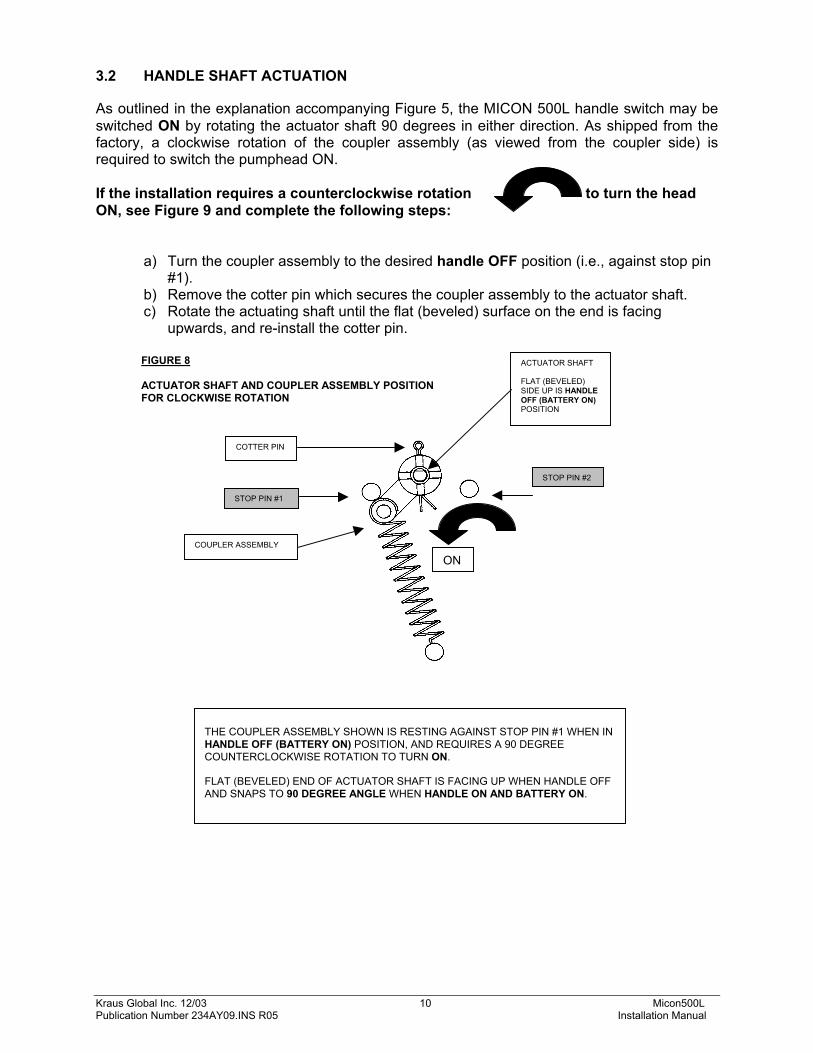
3.2 HANDLE SHAFT ACTUATION As outlined in the explanation accompanying Figure 5, the MICON 500L handle switch may be switched ON by rotating the actuator shaft 90 degrees in either direction. As shipped from the factory, a clockwise rotation of the coupler assembly (as viewed from the coupler side) is required to switch the pumphead ON. If the installation requires a counterclockwise rotation to turn the head ON, see Figure 9 and complete the following steps:
a) Turn the coupler assembly to the desired handle OFF position (i.e., against stop pin #1).
b) Remove the cotter pin which secures the coupler assembly to the actuator shaft. c) Rotate the actuating shaft until the flat (beveled) surface on the end is facing
upwards, and re-install the cotter pin.
THE COUPLER ASSEMBLY SHOWN IS RESTING AGAINST STOP PIN #1 WHEN IN HANDLE OFF (BATTERY ON) POSITION, AND REQUIRES A 90 DEGREE COUNTERCLOCKWISE ROTATION TO TURN ON. FLAT (BEVELED) END OF ACTUATOR SHAFT IS FACING UP WHEN HANDLE OFF AND SNAPS TO 90 DEGREE ANGLE WHEN HANDLE ON AND BATTERY ON.
COUPLER ASSEMBLY
STOP PIN #1
STOP PIN #2
ACTUATOR SHAFT FLAT (BEVELED) SIDE UP IS HANDLE OFF (BATTERY ON) POSITION
COTTER PIN
ON
Kraus Global Inc. 12/03 11 Micon500L Publication Number 234AY09.INS R05 Installation Manual
FIGURE 9 HANDLE SHAFT ACTUATION FOR COUNTERCLOCKWISE ROTATION
3.2 HANDLE SHAFT ACTUATION (CONT’D)
Remove cotter pin from coupler assembly after turning the assembly to the desired OFF position.
Rotate actuating shaft until flat side of actuator shaft faces UP when handle OFF, then re-install cotter pin.
Kraus Global Inc. 12/03 12 Micon500L Publication Number 234AY09.INS R05 Installation Manual
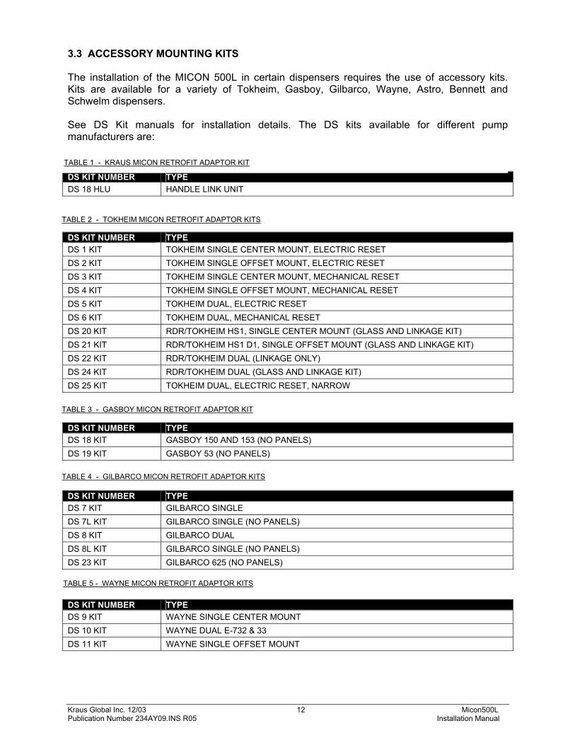
3.3 ACCESSORY MOUNTING KITS The installation of the MICON 500L in certain dispensers requires the use of accessory kits. Kits are available for a variety of Tokheim, Gasboy, Gilbarco, Wayne, Astro, Bennett and Schwelm dispensers. See DS Kit manuals for installation details. The DS kits available for different pump manufacturers are:
DS KIT NUMBER TYPE DS 18 HLU HANDLE LINK UNIT DS KIT NUMBER TYPE DS 1 KIT TOKHEIM SINGLE CENTER MOUNT, ELECTRIC RESET DS 2 KIT TOKHEIM SINGLE OFFSET MOUNT, ELECTRIC RESET DS 3 KIT TOKHEIM SINGLE CENTER MOUNT, MECHANICAL RESET DS 4 KIT TOKHEIM SINGLE OFFSET MOUNT, MECHANICAL RESET DS 5 KIT TOKHEIM DUAL, ELECTRIC RESET DS 6 KIT TOKHEIM DUAL, MECHANICAL RESET DS 20 KIT RDR/TOKHEIM HS1, SINGLE CENTER MOUNT (GLASS AND LINKAGE KIT) DS 21 KIT RDR/TOKHEIM HS1 D1, SINGLE OFFSET MOUNT (GLASS AND LINKAGE KIT) DS 22 KIT RDR/TOKHEIM DUAL (LINKAGE ONLY) DS 24 KIT RDR/TOKHEIM DUAL (GLASS AND LINKAGE KIT) DS 25 KIT TOKHEIM DUAL, ELECTRIC RESET, NARROW
DS KIT NUMBER TYPE DS 18 KIT GASBOY 150 AND 153 (NO PANELS) DS 19 KIT GASBOY 53 (NO PANELS)
DS KIT NUMBER TYPE DS 7 KIT GILBARCO SINGLE DS 7L KIT GILBARCO SINGLE (NO PANELS) DS 8 KIT GILBARCO DUAL DS 8L KIT GILBARCO SINGLE (NO PANELS) DS 23 KIT GILBARCO 625 (NO PANELS)
DS KIT NUMBER TYPE DS 9 KIT WAYNE SINGLE CENTER MOUNT DS 10 KIT WAYNE DUAL E-732 & 33 DS 11 KIT WAYNE SINGLE OFFSET MOUNT
TABLE 2 - TOKHEIM MICON RETROFIT ADAPTOR KITS
TABLE 4 - GILBARCO MICON RETROFIT ADAPTOR KITS
TABLE 5 - WAYNE MICON RETROFIT ADAPTOR KITS
TABLE 3 - GASBOY MICON RETROFIT ADAPTOR KIT
TABLE 1 - KRAUS MICON RETROFIT ADAPTOR KIT
Kraus Global Inc. 12/03 13 Micon500L Publication Number 234AY09.INS R05 Installation Manual
3.3 ACCESSORY MOUNTING KITS (CONT’D) DS KIT NUMBER TYPE DS 12 KIT ASTRO UNIVERSAL DUAL (NO PANELS) DS 13 KIT ASTRO UNIVERSAL SINGLE (NO PANELS) DS KIT NUMBER TYPE DS 14 KIT BENNETT DUAL (NO PANELS) DS 15 KIT BENNETT SINGLE OFFSET MOUNT (NO PANELS) DS 17 KIT BENNETT SINGLE CENTER MOUNT (NO PANELS) DS KIT NUMBER TYPE DS 16 KIT LTS SINGLE SCHWELM METER LPG (NO PANELS) 4.0 CUSTOMER HARNESS LEAD ELECTRICAL CONNECTIONS
TABLE 6 - ASTRO MICON RETROFIT ADAPTOR KITS
TABLE 7 - BENNETT MICON RETROFIT ADAPTOR KITS
TABLE 8 - SCHWELM MICON RETROFIT ADAPTOR KIT
Kraus Global Inc. 12/03 14 Micon500L Publication Number 234AY09.INS R05 Installation Manual
4.1 IMPORTANT WARNINGS
!!! IMPORTANT – PLEASE READ !!!
When performing installation or maintenance work of any kind, including servicing MICON 500L electronic pumphead main boards or using the INFO-PAC to program pumpheads, it is the responsibility of the service person performing the work to ensure: 1. All power to MICON pumphead(s) is turned OFF. 2. All supply of gas to dispenser(s) being serviced is shut OFF. 3. The customer lead exit, located on the top of the explosion-proof
housing, must be properly sealed when exiting into a Division 2 area (North American only). A suitable batting material must first be used to prevent the sealing compound from entering the housing. The seal must be a minimum depth of 5/8 inches or the inside diameter of the opening, whichever is the greater.
4. All wiring must be installed in accordance with national and/or local
electrical codes. 5. All unused wires must be capped or otherwise securely terminated. 6. External equipment connected to the customer harness shall not
exceed or generate more than 125 VAC for all units with 120 VAC rated input or controller outputs.
7. This unit must be connected to an appropriate power source as
specified by the rating nameplate. 8. Independent motor and solenoid power must not exceed the ratings
specified on the rating nameplate.
9. This unit must be grounded by means of all ground wires provided.
10. The local supply ground to which this device is connected and/or any metal structure upon which this unit is mounted shall be at the same potential as the I.S. barrier ground.
CAUTION
!
Kraus Global Inc. 12/03 15 Micon500L Publication Number 234AY09.INS R05 Installation Manual
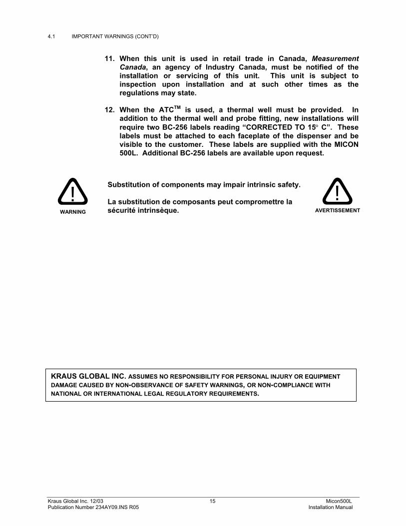
4.1 IMPORTANT WARNINGS (CONT’D)
11. When this unit is used in retail trade in Canada, Measurement Canada, an agency of Industry Canada, must be notified of the installation or servicing of this unit. This unit is subject to inspection upon installation and at such other times as the regulations may state.
12. When the ATCTM is used, a thermal well must be provided. In
addition to the thermal well and probe fitting, new installations will require two BC-256 labels reading “CORRECTED TO 15° C”. These labels must be attached to each faceplate of the dispenser and be visible to the customer. These labels are supplied with the MICON 500L. Additional BC-256 labels are available upon request.
Substitution of components may impair intrinsic safety. La substitution de composants peut compromettre la sécurité intrinsèque.
KRAUS GLOBAL INC. ASSUMES NO RESPONSIBILITY FOR PERSONAL INJURY OR EQUIPMENT DAMAGE CAUSED BY NON-OBSERVANCE OF SAFETY WARNINGS, OR NON-COMPLIANCE WITH NATIONAL OR INTERNATIONAL LEGAL REGULATORY REQUIREMENTS.
WARNING !
AVERTISSEMENT
!
Kraus Global Inc. 12/03 16 Micon500L Publication Number 234AY09.INS R05 Installation Manual
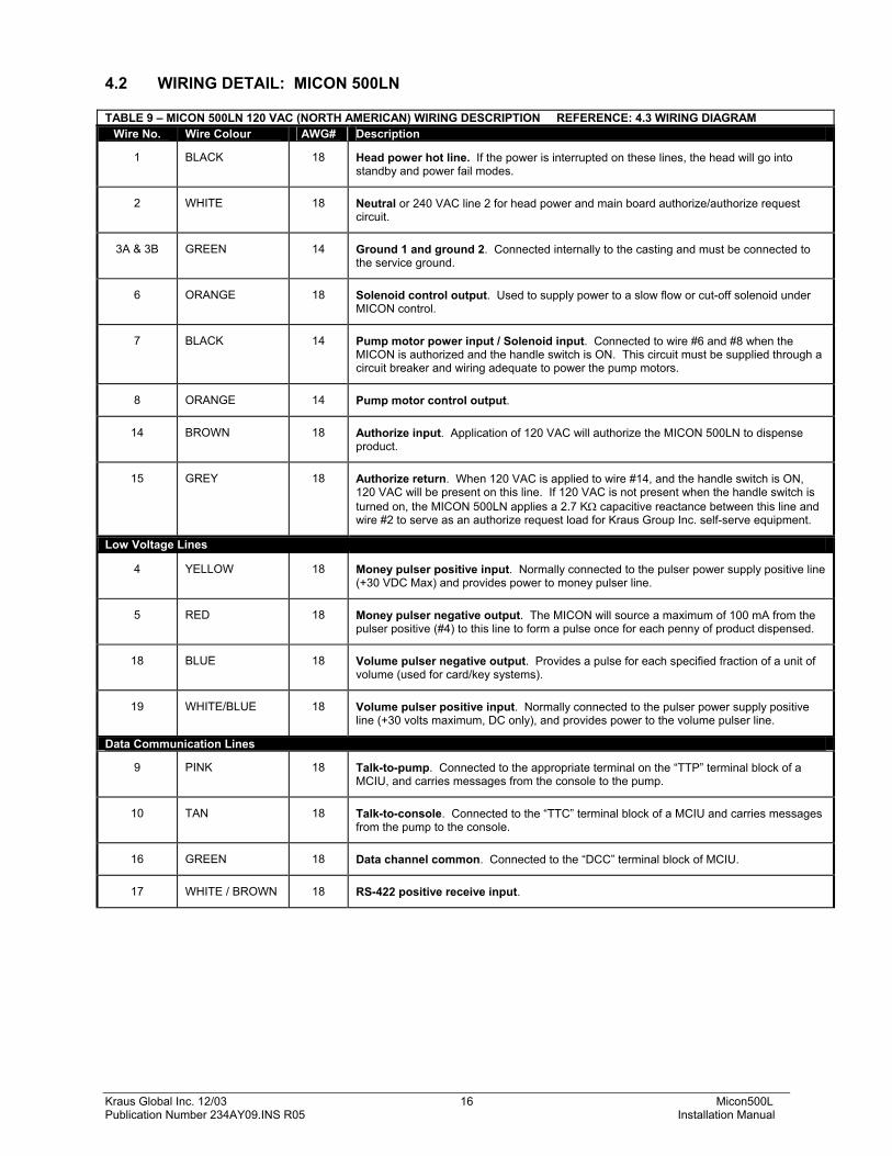
1 BLACK 18 Head power hot line. If the power is interrupted on these lines, the head will go into standby and power fail modes.
2 WHITE 18 Neutral or 240 VAC line 2 for head power and main board authorize/authorize request circuit.
3A & 3B GREEN 14 Ground 1 and ground 2. Connected internally to the casting and must be connected to the service ground.
6 ORANGE 18 Solenoid control output. Used to supply power to a slow flow or cut-off solenoid under MICON control.
7 BLACK 14 Pump motor power input / Solenoid input. Connected to wire #6 and #8 when the MICON is authorized and the handle switch is ON. This circuit must be supplied through a circuit breaker and wiring adequate to power the pump motors.
8 ORANGE 14 Pump motor control output.
14 BROWN 18 Authorize input. Application of 120 VAC will authorize the MICON 500LN to dispense product.
15 GREY 18 Authorize return. When 120 VAC is applied to wire #14, and the handle switch is ON, 120 VAC will be present on this line. If 120 VAC is not present when the handle switch is turned on, the MICON 500LN applies a 2.7 KΩ capacitive reactance between this line and wire #2 to serve as an authorize request load for Kraus Group Inc. self-serve equipment.
Low Voltage Lines
4 YELLOW 18 Money pulser positive input. Normally connected to the pulser power supply positive line (+30 VDC Max) and provides power to money pulser line.
5 RED 18 Money pulser negative output. The MICON will source a maximum of 100 mA from the pulser positive (#4) to this line to form a pulse once for each penny of product dispensed.
18 BLUE 18 Volume pulser negative output. Provides a pulse for each specified fraction of a unit of volume (used for card/key systems).
19 WHITE/BLUE 18 Volume pulser positive input. Normally connected to the pulser power supply positive line (+30 volts maximum, DC only), and provides power to the volume pulser line.
Data Communication Lines
9 PINK 18 Talk-to-pump. Connected to the appropriate terminal on the “TTP” terminal block of a MCIU, and carries messages from the console to the pump.
10 TAN 18 Talk-to-console. Connected to the “TTC” terminal block of a MCIU and carries messages from the pump to the console.
16 GREEN 18 Data channel common. Connected to the “DCC” terminal block of MCIU.
17 WHITE / BROWN 18 RS-422 positive receive input.
Kraus Global Inc. 12/03 17 Micon500L Publication Number 234AY09.INS R05 Installation Manual
4.3 MICON 500LN WIRING DIAGRAM
Kraus Global Inc. 12/03 18 Micon500L Publication Number 234AY09.INS R05 Installation Manual
4.4 WIRING DETAIL: MICON 500LE TABLE 10 - MICON 500LE 230 VAC (EUROPEAN) WIRING DESCRIPTION REFERENCE: 4.5 WIRING DIAGRAM Wire No. 230 VAC Lines - (metric type shielded cable) YEL/GRN Earth. Connected internally to the casting and must be connected to the service ground.
1 230 VAC head power hot line. If power is interrupted on this line, the head will go into standby and power-fail modes.
2 Neutral for head power and main board authorize/authorize request circuit. 3 Motor Output. 4 Motor/Solenoid Power 5 Solenoid Output. 6 Not Used 7 Not Used 8 Not Used
19 Authorize output. When 230 VAC is applied to wire #20 and the handle switch is on, 230 VAC will be present on this line. (3 Amp. maximum load)
20 Authorize input. Application of 230 VAC will “authorize” the MICON to dispense product. If 230 VAC is not present when the handle switch is turned on, the MICON applies a 14 KΩ capacitive reactance between this line and wire #2 to serve as an authorize request load for Kraus Industries Self-Serve equipment.
Wire No. Low Voltage Lines 9 Money pulser positive. Normally connected to the pulser power supply positive line (+30 volts maximum, DC
only) and provides power to the money and volume pulser lines. 10 Money pulser negative. The MICON will source a maximum of 100 mA from the pulser common (#9) to this
line to form a pulse once for each penny of product dispensed. (Used with KRAUS MONITOR and MICRO consoles.)
11 Volume pulser negative. Provides a pulse (as described above for money pulser) for each specified fraction of a unit of volume. (Used for card or key systems.)
15 Not used. 16 Not used 17 Not used 18 Not used 22 Volume pulser positive. Provides power to the volume pulser line.
Wire No. Micro 2, Concept 5000 & MCIU Data Communications Lines 12 Data channel common. This line is connected to the “DCC” terminal block of a MCIU. 13 Talk-to-console. This line is connected to the “TTC” terminal block of a MCIU and carries messages from the
pump to the console. 14 Talk-to-pump. This line is connected to the appropriate terminal on the “TTP” terminal block of a MCIU and
carries messages from the console to the pump. 21 RS-422 positive input.
Kraus Global Inc. 12/03 19 Micon500L Publication Number 234AY09.INS R05 Installation Manual
4.5 MICON 500LE WIRING DIAGRAM
Kraus Global Inc. 12/03 20 Micon500L Publication Number 234AY09.INS R05 Installation Manual
4.6 COMMUNICATION INTERFACE CONNECTIONS Tables 12 and 13 below describe communication interface connections for the following interface options: • Tokheim Interface • Gilbarco Interface • Tatsuno Interface • RS-422 Interface • RS-232 Interface • Kraus MNET Interface TABLE 11 – COMMUNICATIONS INTERFACE CONNECTIONS FOR THE MICON 500LN (NORTH AMERICAN)
Customer Harness Wire #
Tokheim Interface
Gilbarco 2-Wire
Interface
Tatsuno Interface
RS-422 Interface
RS-232 Interface
Kraus MNET
Interface 16 DCC Not used Not used OUT “+” Gnd DCC 10 TTC 2-wire “+” “+” OUT “-” Tx TTC 9 TTD 2-wire “-” “-” IN “-” Rx TTP
17 Not used Not used Not used IN “+” Not used Not used TABLE 12 – COMMUNICATIONS INTERFACE CONNECTIONS FOR THE MICON 500LE (EUROPEAN)
Customer Cable Wire
#
Tokheim Interface
Gilbarco 2-Wire
Interface
Tatsuno Interface
RS-422 Interface
RS-232 Interface
Kraus MNET
Interface 12 DCC Not used Not used OUT “+” Gnd DCC 13 TTC 2-wire “+” “+” OUT “-” Tx TTC 14 TTD 2-wire “-” “-” IN “-” Rx TTP 21 Not used Not used Not used IN “+” Not used Not used
Kraus Global Inc. 12/03 21 Micon500L Publication Number 234AY09.INS R05 Installation Manual
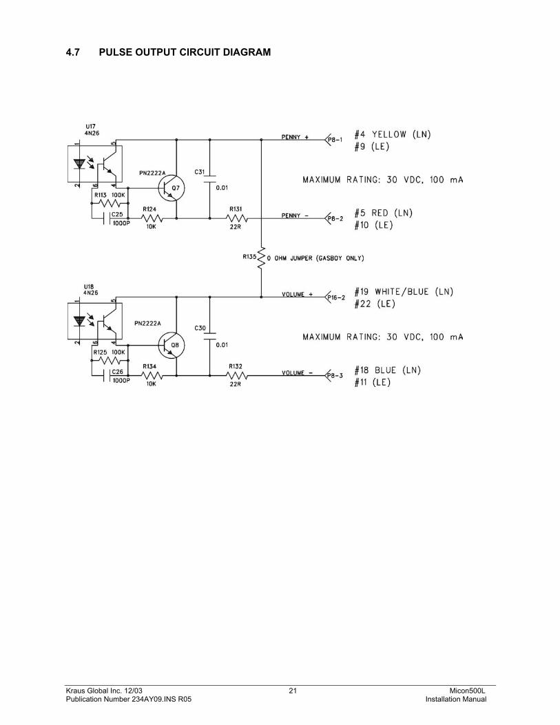
4.7 PULSE OUTPUT CIRCUIT DIAGRAM
Kraus Global Inc. 12/03 22 Micon500L Publication Number 234AY09.INS R05 Installation Manual
4.8 DUAL TWO PRODUCT DISPENSER WIRING DIAGRAM
Kraus Global Inc. 12/03 23 Micon500L Publication Number 234AY09.INS R05 Installation Manual
4.9 DUAL SINGLE PRODUCT DISPENSER WIRING DIAGRAM
Kraus Global Inc. 12/03 24 Micon500L Publication Number 234AY09.INS R05 Installation Manual
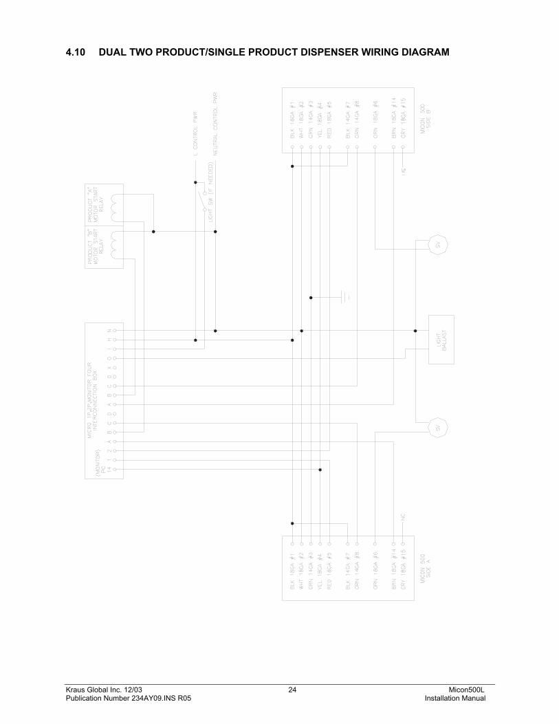
4.10 DUAL TWO PRODUCT/SINGLE PRODUCT DISPENSER WIRING DIAGRAM
Kraus Global Inc. 12/03 25 Micon500L Publication Number 234AY09.INS R05 Installation Manual
FIGURE 10 PRICE SETTING USING THE MICON COMMUNICATOR
5.0 POST INSTALLATION CHECK After completing the installation of the MICON and checking all wiring connections, correct operation should be verified as follows:
1. Enter a price, as described below (also described in section 6.2.2 – Setting Prices on a Single Tier Dispenser). a) Go to breaker box and turn OFF AC power to MICON 500L electronic pumphead being
serviced. Caution: Ensure breaker box does not feed power to equipment which should remain ON.
MICON display should be flashing.
If display is not flashing, unit is in sleep mode. To correct this, turn handle ON and OFF. Display will start flashing.
b) Take the MICON hand held communicator and go to the front display of the MICON 500L electronic pumphead display.
c) Aim the communicator at the optical sensor (oval hole ) at right of price display on MICON 500L.
d) To set prices:
While aiming the communicator’s transmitter (located on the end of the unit) at the MICON 500L optical display sensor, press and hold the “SET” until the display increments to the desired number.
Use the “SEL” key to select the next digit to be changed. Press and hold the “SET” key until the display increments to the desired number.
2. After entering a price, turn ON the 120 VAC (230 VAC European) MICON head
power. 3. Place the dispenser handle in the OFF position. Turn ON dispenser sequencing
power and ensure that no product can be dispensed. 4. If card lock equipment is being used, place the dispenser handle in the ON
position. Authorize the MICON. This is normally done by inserting the appropriate card into the card terminal, then entering data (i.e., i.d. number, mileage, etc.) as required. The authorization signal received by the card terminal is sent to the MICON 500L head via input wire #14 (N. American) or #20 (European).
MICON hand held communicator
MICON 500L electronic pumphead display
Aim end of communicator at optical sensor
Kraus Global Inc. 12/03 26 Micon500L Publication Number 234AY09.INS R05 Installation Manual
5.0 POST INSTALLATION CHECK (CONT’D)
5. For stand alone operation, turn ON the dispenser handle. The authorization in this case is bypassed and the main board receives a direct signal. The display resets and the main flow valve is signaled by the MICON to open and commence fuel flow.
6. When resetting, displays should flash to all 8’s momentarily, go blank, then return to zero. Now the solenoid valve controlling fuel flow should energize.
7. Dispense a convenient amount of product into a test can and check that the MICON 500L displays the proper volume and dollars amount. For testing the MICON 500L with ATCTM option refer to section 8.
8. Place the dispenser handle in the OFF position and ensure that the pump motor and/or solenoid shuts off.
This completes the post installation check. If the unit does not function as described above, contact your factory or service representative.
The method used to set prices to MICON 500L electronic pumpheads is dependent upon the type of self serve consoles employed.
If you are using Kraus Global Inc. Monitor 4 Console Systems, refer to sections
6.2.1- Reading Totalizers and 6.2.2 – Setting Prices, for information regarding price changes and reading of totalizers.
If you are using a Kraus Global Inc. Micon Communication Interface Unit (MCIU),
MICON 500L totalizers and prices may be accessed through the console. Refer to owner’s manual for details.
If it is necessary to place the station in manual mode of operation, all of the affected dispensers must be “reset”:
1. Place the console Emergency switch in the Emergency position and wait for all MICON 500L registers to go blank.
2. Return the Emergency switch to the normal position and place the manual switch in the manual position. The station may now be operated in the manual mode.
3. Manual mode switch switches AC power to line #14 (North American or line #20 (European: Authorize). In manual mode when emergency switch in position, AC power is removed from solenoid power line.
6.2 MICON 500L COMMUNICATOR OPERATION
ATTENTION !
Kraus Global Inc. 12/03 27 Micon500L Publication Number 234AY09.INS R05 Installation Manual
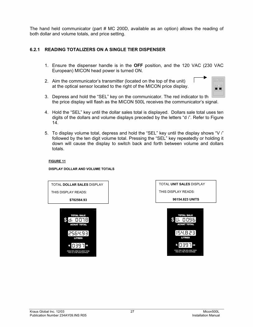
FIGURE 11 DISPLAY DOLLAR AND VOLUME TOTALS
The hand held communicator (part # MC 200D, available as an option) allows the reading of both dollar and volume totals, and price setting.
6.2.1 READING TOTALIZERS ON A SINGLE TIER DISPENSER
1. Ensure the dispenser handle is in the OFF position, and the 120 VAC (230 VAC European) MICON head power is turned ON.
2. Aim the communicator’s transmitter (located on the top of the unit)
at the optical sensor located to the right of the MICON price display. 3. Depress and hold the “SEL” key on the communicator. The red indicator to the left of
the price display will flash as the MICON 500L receives the communicator’s signal.
4. Hold the “SEL” key until the dollar sales total is displayed. Dollars sale total uses ten digits of the dollars and volume displays preceded by the letters “d l”. Refer to Figure 14.
5. To display volume total, depress and hold the “SEL” key until the display shows “V l”
followed by the ten digit volume total. Pressing the “SEL” key repeatedly or holding it down will cause the display to switch back and forth between volume and dollars totals.
TOTAL DOLLAR SALES DISPLAY THIS DISPLAY READS:
$782564.93
TOTAL UNIT SALES DISPLAY THIS DISPLAY READS:
96154.823 UNITS
Kraus Global Inc. 12/03 28 Micon500L Publication Number 234AY09.INS R05 Installation Manual
FIGURE 12 PRICE SETTING USING THE MICON COMMUNICATOR
6.2.2 SETTING PRICES ON A SINGLE TIER DISPENSER
1. Go to breaker box and turn OFF AC power to MICON 500L electronic pumphead
being serviced. Caution: Ensure breaker box does not feed power to equipment which should remain ON.
MICON display should be flashing.
If display is OFF, unit is in sleep mode. To correct this, turn handle ON and OFF. Display will start flashing. The dollar (top) display on the MICON 500L displays the dollar amount and “Prc 1”.
2. Take the MICON hand held communicator and go to the front display of the MICON
500L electronic pumphead. 3. Aim the communicator at the optical sensor (oval hole ) at right of price
display on MICON 500L.
4. To set prices: While aiming the communicator’s transmitter (located on the end of the unit) at
the MICON 500L optical display sensor, press and hold the “SET” key until the MICON display increments to the desired number.
Use the “SEL” key to select the next digit to be changed. Press and hold the
“SET” key until the display increments to the desired number. When the correct price per unit has been entered, restore head power while
handle switch remains in the OFF position.
MICON hand held communicator
MICON 500L electronic pumphead display
Aim end of communicator at optical sensor
Kraus Global Inc. 12/03 29 Micon500L Publication Number 234AY09.INS R05 Installation Manual
6.3 TWO TIER PRICE OPERATION On MICON 500L units equipped with the two tier price option it is possible to make sales at two different prices. For example, cardholders may receive a discount from the regular price while fuel is dispensed to non-cardholders at full price. The unit maintains separate totalizers for each price of sales. 6.3.1 TWO TIER OPTION INSTALLATION Two tier installation requires a connector (included with part #W392 - harness) and pricing push-button switch (part #PWP 320) or key-switch (part #Y101). To order these optional parts contact your local service representative. To install the two tier option:
Connect the push button switch between the blue and orange wires on the provided connector. The push button switch can then be mounted in a 7/8” hole in the side of the dispenser.
An optional key-switch is available, which can be used instead of, or together with,
the push-button. Wire the key-switch and push-button in series, not parallel.
6.3.2 SETTING PRICES ON A TWO TIER DISPENSER Setting prices on a two tier dispenser is the same as on a single tier dispenser, except that pressing the DISCOUNT button will change which price is being set.
1. To set “Prc 1”, which is the regular price, turn OFF AC head power at the breaker
box. The display should be flashing. The dollar display on the MICON 500L displays the dollar amount and “Prc 1” at first.
Set this price by aiming the communicator’s transmitter (on top of unit) at the optical sensor (oval hole ) at right of price display on MICON 500L. Press the SEL key to select the digit to be changed, and press the SET key to increment to the desired number.
2. To set “Prc 2”, which is the discounted price, press the DISCOUNT button
located on the side of the dispenser. The dollar display on the MICON 500L will then display the dollar amount and “Prc 2” at first. “Prc 2” indicates the discounted price. Set this price by aiming the communicator at the optical sensor (oval hole ) at right of price display on MICON 500L. Press the SEL key to select the digit to be changed, and press the SET key to increment to the desired number.
Kraus Global Inc. 12/03 30 Micon500L Publication Number 234AY09.INS R05 Installation Manual
6.3.3 MAKING DISCOUNT PRICE SALES ON A TWO TIER DISPENSER
1. To make a discount priced sale, simply press the DISCOUNT push button, located on the side of the dispenser, before turning the dispenser handle ON. When the button is pressed, the discount price will be displayed. The next sale will proceed at the discount price. If the DISCOUNT button is pressed by mistake and you do not wish to make a
discounted sale, simply press the DISCOUNT button again and the dispenser will revert back to the regular price.
Pressing the DISCOUNT button while the dispenser handle is in the ON position has
no effect on the dispenser. 2. When the discounted sale is completed, turn the dispenser handle to the OFF
position. The regular price will again be displayed and subsequent sales will occur at the regular price.
The INFO-PAC used to monitor and program the MICON 500L pumpheads has a setting intended for use when two tier (regular and discount) pricing is in effect: PRC RESTORE (price restore). When this setting is ON (default setting), the MICON automatically reverts back to tier 1 (regular pricing) after each discounted transaction. It is possible to set PRC RESTORE OFF, in which case the price used for the current sale is retained for the next sale. Refer to INFO-PAC MICON 500L Programming Manual for details.
6.3.4 READING TOTALIZERS ON A TWO TIER DISPENSER Reading volume and dollar totals on two tier dispenser totalizers is the same as on single tier dispensers totalizers, except that pressing the DISCOUNT button will change which volume/dollar setting (regular or discount) is being read.
The two tier dispenser contains two sets of totalizers: volume and dollar totals for regular priced sales; volume and dollar totals for the discount priced sales.
To read the totalizers:
1. Proceed as on page 27 by ensuring the dispenser handle is in the OFF position,
and the 120 VAC (230 VAC European) MICON head power is turned ON. Display should be flashing. Aim the communicator’s transmitter (on top of unit) at the optical sensor (oval hole ) at right of price display on MICON 500L. Press and hold the SEL key until the dollar sales total is displayed.
NOTE !
Kraus Global Inc. 12/03 31 Micon500L Publication Number 234AY09.INS R05 Installation Manual
FIGURE 13 READING TOTALIZERS
6.3.4 READING TOTALIZERS ON A TWO TIER DISPENSER (CONT’D)
2. Display will show “d I” for regular dollar totals. Press the DISCOUNT button. Display will show “d I I” for discount dollar totals.
3. Press the SEL key until the display shows “v I” (regular priced volume total) or “v I I”
(discount priced volume total). Press the DISCOUNT button to switch back and forth between “v I” and “v I I”.
4. Press and hold the SEL to switch back and forth between dollar and volume total
displays. Manually adding regular and discount volume or dollar totals will yield grand sales totals.
6.4 ELECTRONIC AUDIT TRAILS The MICON 500L is equipped with electronic audit trails in the form of non-resettable event counters. This feature is facilitated in software, and meets the current requirements of Measurement Canada regulations. The top display of the MICON 500L electronic pumphead indicates the number of changes to device configuration parameters performed with the INFO-PAC, as shown in Fig. 3.
display reads $782564.93
REGULAR TOTAL DOLLAR SALES DISPLAY
DISCOUNT TOTAL DOLLAR SALES DISPLAY
display reads $704308.44
press DISCOUNT button on dispenser side to switch back and forth
display reads 96154.823 units
display reads 86539.343 units
REGULAR TOTAL VOLUME SALES DISPLAY
DISCOUNT TOTAL VOLUME SALES DISPLAY
press DISCOUNT button on dispenser side to switch back and forth
press SEL key on communicator to switch between dollar and volume displays
Kraus Global Inc. 12/03 32 Micon500L Publication Number 234AY09.INS R05 Installation Manual
7.0 ELECTRONIC CALIBRATOR ADJUSTMENT The MICON 500L is equipped with an electronic calibration feature. This feature provides the MICON 500L with the capability of electronically compensating for meter errors of +/-19.99%. The required calibration error is programmed into the MICON via the INFO-PAC hand held programming device. The factory default is set for 0% calibration error. If the meter is correctly calibrated, no further adjustment is necessary. When the inspection switch (connected between P12-1 and P12-5) is turned ON, the MICON will display calibration information or ATCTM (automatic temperature compensation) information (if ATCTM is installed). The display then indicates: TOP DISPLAY temperature (ATCTM installed and ON) % calibration (ATCTM OFF) CENTER DISPLAY uncompensated vol. (same as normal volume if ATCTM is OFF or not
installed) BOTTOM DISPLAY flow rate/status Until flow begins, the product compensation type will be displayed for one of the following products:
GAS = GASOLINE ProP = propane dESL = diesel fuel OFF = ATC turned OFF or not installed
If calibration adjustment is required, follow guidelines below:
1. To receive MICON 500L settings with the INFO-PAC, follow steps as outlined below:
To receive information from the MICON 500L: 1) Go to breaker box and turn power OFF. Caution: Ensure breaker box does not feed power to equipment which should remain ON. The MICON 500L display should be flashing. If display is blank, unit is in sleep (i.e., battery save) mode. To correct this, turn handle ON and OFF. Display will start flashing. 2) Turn INFO-PAC ON by pressing left arrow key. Using up or down arrow key, scroll to INFO-PAC RX MICON option. Set RX MICON on by pressing left or right pointing arrow key. 3) Take INFO-PAC and go to the front display of the MICON 500L electronic pumphead. Locate optical sensor (oval “hole”) at right of price display on MICON 500L. Aim INFO-PAC receiver / transmitter (located behind red tinted filter at centre edge of INFO-PAC) at MICON 500L optical sensor. Red LED (light emitting diode) to left of MICON 500L price display flashes as INFO-PAC receives data from MICON 500L. 4) When INFO-PAC has received a copy of the MICON 500L setup information correctly, INFO-PAC display will show “Received Micon”. To view each setting, scroll with the up or down arrow key. 2. If MICON 500L is equipped with ATCTM, set INFO-PAC menu option ATC off.
Kraus Global Inc. 12/03 33 Micon500L Publication Number 234AY09.INS R05 Installation Manual
7.0 ELECTRONIC CALIBRATOR ADJUSTMENT (CONT’D) 3. Set INFO-PAC calibration factor to C.FACTOR +00.00% (default). 4. Follow steps to transmit INFO-PAC settings to MICON 500L, outlined in the INFO-PAC
MICON 500L Programming Manual and described below.
To transmit information to the MICON 500L: 1. Switch OFF the head power to the MICON 500L, by removing cover of explosion-proof MICON 500L housing and
removing fuse. The MICON 500L display should be flashing. This requires breaking of a Weights and Measures seal on the cover, and removal of bolts. Flip switch inside MICON 500L to enable programming mode.
2. Scroll to INFO-PAC TRANSMIT option. Set TRANSMIT on. Before transmitting settings from the INFO-PAC to the MICON 500L electronic pumphead, scroll carefully through
all options displayed on the INFO-PAC, and ensure that each and every one is still on the desired setting, even if you have changed only a single setting.
Whenever programming with the INFO-PAC, ALL parameters are rewritten in the MICON 500L. 3. Locate optical sensor (oval “hole” ) at right of price display on MICON 500L. 4. Aim INFO-PAC transmitter/receiver (located in center behind red tinted filter on edge of INFO-PAC) at MICON 500L
optical sensor. Red LED to left of MICON 500L price display flashes as MICON receives data from INFO-PAC.
5. When MICON 500L has correctly received setup information, will show on MICON 500L price display.
Exit programming mode by flipping switch inside MICON 500L to DOWN (Normal position). 7. Switch the head power back ON and run the MICON 500L using the new settings. 8. Replace the cover of the explosion-proof MICON 500L housing and: a) Install a suitable legal seal through the two adjacent drilled cover bolts to ensure the cover cannot be removed without breaking the seal. b) Install a suitable legal handle seal through the handle shaft, behind the cotter pin, so that the handle coupler cannot be removed from the handle shaft. 5. Place MICON 500L handle switch in ON position. Observe MICON dollars and volume
displays reset to zero. 6. Dispense a known volume of product and record the reading on the volume display.
Kraus Global Inc. 12/03 34 Micon500L Publication Number 234AY09.INS R05 Installation Manual
7.0 ELECTRONIC CALIBRATOR ADJUSTMENT (CONT’D) 7. Use formula below to calculate percentage correction required: % Correction = Actual Volume - Register Volume X 100 Register Volume 8. Set calibration factor on INFO-PAC to the closest setting available. Example Product dispensed: 25.00 Litres Register reading: 26.360 Litres % Correction = (25.000 – 26.360) X 100 = - 5.159% 26.360 Set INFO-PAC calibration factor to C.FACTOR – 5.16%. Place the programming switch into program mode and transmit the calibration factor to the
MICON with the TRANSMIT function. The dollars section of the MICON 500L display would show “-5.16” for the example given.
9. Repeat steps 5 and 6, to verify the calibration of the MICON 500L. 10. If ATCTM used at this installation, set ATCTM INFO-PAC menu option ATC on, and
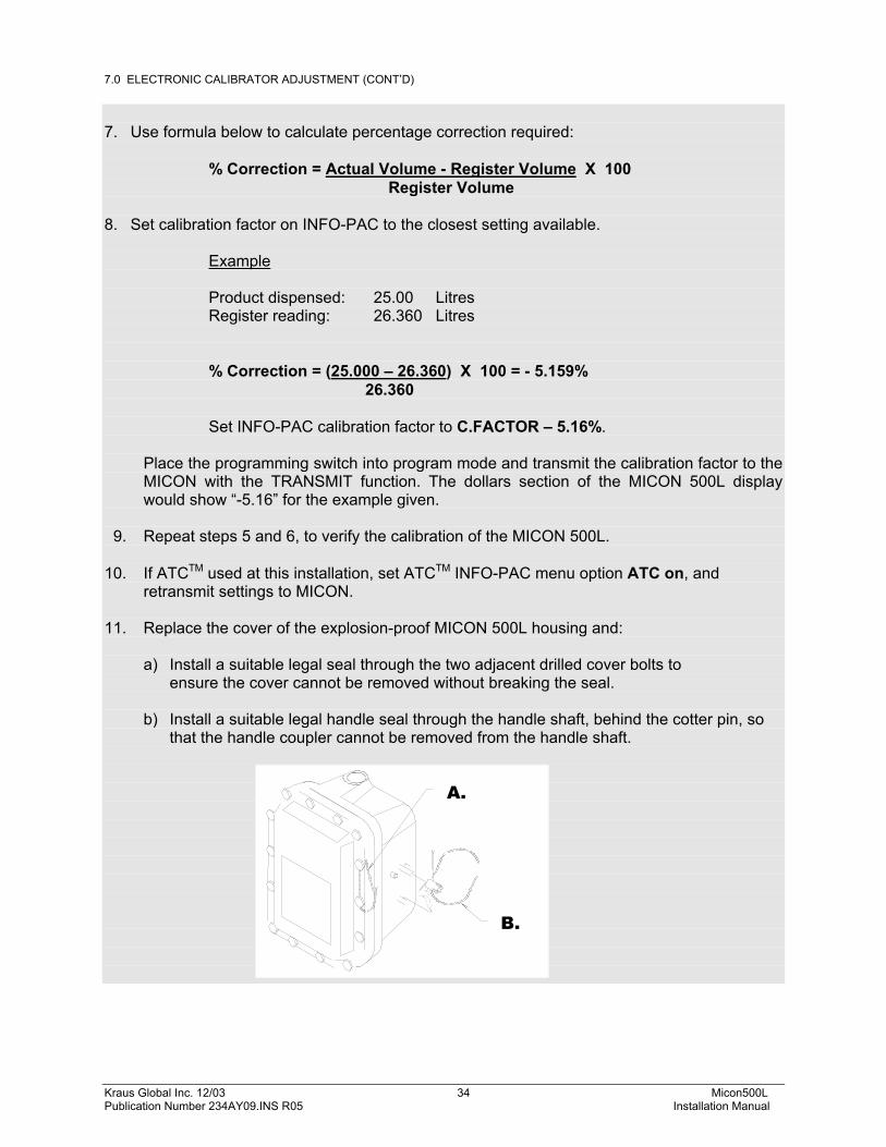
retransmit settings to MICON. 11. Replace the cover of the explosion-proof MICON 500L housing and: a) Install a suitable legal seal through the two adjacent drilled cover bolts to ensure the cover cannot be removed without breaking the seal. b) Install a suitable legal handle seal through the handle shaft, behind the cotter pin, so
that the handle coupler cannot be removed from the handle shaft.
B.
A.
Kraus Global Inc. 12/03 35 Micon500L Publication Number 234AY09.INS R05 Installation Manual
8.0 AUTOMATIC TEMPERATURE COMPENSATION The MICON 500L is optionally available with automatic temperature compensation of the product dispensed. To install the MICON 500L with the ATCTM feature, it will be necessary to install the temperature probe and a test well in the meter line.
It is a requirement of Measurement Canada, an agency of Industry Canada, that a thermal well be provided next to the installed temperature probe, for inspection purposes. The following guidelines should be observed when installing an inspection test well: 1. The thermal well must be positioned to retain thermally conductive fluid.
The hole in the fuel line should be drilled (drill size Q) so that the well will be at an angle within 45° of vertical when the well is installed and the assembly is reconnected.
2. Install a 1/8 inch NPT test well extension fitting (Kraus part # BC 546) if needed, into the hole which was drilled into the fuel line. The inside of the 1/8 inch NPT fitting will be drilled out to accommodate the insertion of the test well (Kraus part # BC 407).
• Test well and probe are to be as close together as practical and the
test well must be accessible to the inspector after installation. Fittings are supplied with the MICON 500L (additional fittings available upon request).
• The fitting should provide easy access for the insertion of a
thermometer. • The fitting should be placed in an appropriate location so as not to
hinder reinstallation of the assembly.
3. Install the test well into the extension fitting and tighten into place.
4. Cover the test well assembly with the supplied protective plug.
FIGURE 14 THERMAL WELL LOCATION
TEMPERATURE PROBE
THERMAL TEST WELL
ATTENTION
!
Kraus Global Inc. 12/03 36 Micon500L Publication Number 234AY09.INS R05 Installation Manual
8.0 AUTOMATIC TEMPERATURE COMPENSATION (CONT’D)
If the connection is made with less than 5 threads fully engaged, it will be necessary to solder the fitting into place. Connections which are in excess of 5 full threads do not require soldering, but must make use of a thread sealing compound suitable for use with the intended fuel type.
In addition to the test well and probe fitting, new installations will require two BC-256 labels ("CORRECTED TO 15°C"). These labels must be attached to each faceplate of the dispenser and be visible to the customer. Labels are provided with MICON 500L and additional labels are available upon request. The Automatic Temperature Compensator feature compensates the volume of product delivered to the equivalent volume at 15 degrees Celsius (15oC default). In order to accurately sense the temperature of the product, the probe must be directly immersed into the product as close as possible to the meter. The following procedure should be used to verify the operation of the ATCTM:
1. Install and connect the temperature probe. 2. Turn the inspection switch to the ATCTM position. 3. Dispense a convenient volume of product into a test can and record the temperature
and volume of the product in the can. 4. The volume indicated on the display of the MICON 500L is the UNCOMPENSATED
volume. This volume should agree directly with the volume measured in the test can. If it does not agree, the meter is out of calibration.
5. Calculate the compensated volume in the test can using the actual volume and the
temperature of the product in the test can and the appropriate correction tables. The calculated compensated volume should agree with the compensated volume shown when inspection switch in “normal” display position. If the values do not agree, a problem exists in the MICON or its installation.
6. Return the inspection switch to the upwards position for "normal" display position.
This completes the testing of the ATCTM. If you encounter any difficulty please contact your service representative.
ATTENTION
!
Kraus Global Inc. 12/03 37 Micon500L Publication Number 234AY09.INS R05 Installation Manual
9.0 PULSER ASSEMBLY REPLACEMENT If troubleshooting procedures indicate a defective pulser board and / or disk then the entire base assembly should be replaced as described in steps 1 to 6, as follows:
This does not apply to remote pulsers.
1. Remove the MICON face plates. 2. Unplug the harness that enters the pulser housing. 3. Remove any other necessary hardware in order to slide the base out from under
the explosion proof housing (it may be necessary to loosen the conduit coupling to lift the tub assembly).
4. Install the new base assembly. 5. Reassemble the MICON. Connect the wire harness.
Reverse polarity of the two signal lines: WHITE wire provides leading digital signal; YELLOW wire provides lagging digital signal. If polarity of pulser board is not reversed, solenoid valve will shut OFF whenever flow is detected.
6. Test the dispenser for proper operation.
NOTE !
NOTE !
Kraus Global Inc. 12/03 38 Micon500L Publication Number 234AY09.INS R05 Installation Manual
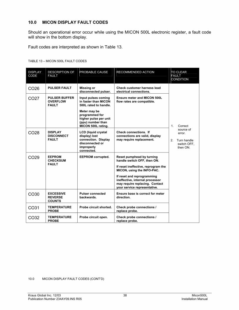
10.0 MICON DISPLAY FAULT CODES
Should an operational error occur while using the MICON 500L electronic register, a fault code will show in the bottom display. Fault codes are interpreted as shown in Table 13.
TABLE 13 – MICON 500L FAULT CODES
DISPLAY CODE
DESCRIPTION OF FAULT
PROBABLE CAUSE RECOMMENDED ACTION TO CLEAR FAULT CONDITION
CO26 PULSER FAULT Missing or disconnected pulser.
Check customer harness lead electrical connections.
CO27 PULSER BUFFER OVERFLOW FAULT
Input pulses coming in faster than MICON 500L rated to handle.
Meter may be programmed for higher pulse per unit (ppu) number than MICON 500L rating.
Ensure meter and MICON 500L flow rates are compatible.
CO28 DISPLAY DISCONNECT FAULT
LCD (liquid crystal display) lost connection. Display disconnected or improperly connected.
Check connections. If connections are valid, display may require replacement.
CO29 EEPROM CHECKSUM FAULT
EEPROM corrupted. Reset pumphead by turning handle switch OFF, then ON.
If reset ineffective, reprogram the MICON, using the INFO-PAC.
If reset and reprogramming ineffective, internal processor may require replacing. Contact your service representative.
Kraus Global Inc. 12/03 40 Micon500L Publication Number 234AY09.INS R05 Installation Manual
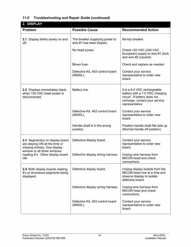
11.0 Troubleshooting and Repair Guide
If, after installation, the dispenser does not operate as it is supposed to, the following tables should be consulted before calling your service representative.
Troubleshooting tables have been divided alphabetically into the following categories:
1. communicator
2. display
3. (MICON) pumphead power
4. pump motor and/or solenoid valve
5. registration
1. COMMUNICATOR
Problem Possible Cause Recommended Action
1.1 Unable to read totals or price setting with the communicator, but it functions normally with other MICON heads.
Defective optical reader on the display board. Defective display wiring harness. Defective KIL 463 control board (M500L). Older communicators may not work on newer MICONS, the communicator may need to be replaced or modified.
Replace display board. Replace harness. Contact your service representative to order new board. Contact your service representative for communicator upgrade or replacement.
1.2 Communicator exhibits poor range when attempting to set prices or read totals on all MICON heads.
Optical reader is in direct sunlight. Weak or dead battery in communicator.
Shade optical reader with hand. Unscrew back of communicator and replace 9 volt transistor battery.
Kraus Global Inc. 12/03 41 Micon500L Publication Number 234AY09.INS R05 Installation Manual
11.0 Troubleshooting and Repair Guide (continued)
2. DISPLAY
Problem Possible Cause Recommended Action 2.1 Display blinks slowly on and off.
The breaker supplying power to wire #1 has been tripped. No head power. Blown fuse. Defective KIL 463 control board (M500L).
Re-trip breaker. Check 120 VAC (240 VAC European) supply to wire #1 (hot) and wire #2 (neutral). Check and replace as needed. Contact your service representative to order new board.
2.2 Displays immediately blank when 120 VAC head power is disconnected.
Battery low. Defective KIL 463 control board (M500L). Handle shaft is in the wrong position.
It is a 6.0 VDC rechargeable battery with a 7.0 VDC charging circuit. If battery does not recharge, contact your service representative. Contact your service representative to order new board Position handle shaft flat side up (Normal handle off position).
2.3 Segment(s) on display board are staying ON all the time or missing entirely. One display window or all three windows reading 8’s. Other display board OK.
Unplug display boards from the MICON head one at a time and observe display to isolate defective board. Unplug wire harness from MICON head and check connections. Contact your service representative to order new board.
Kraus Global Inc. 12/03 42 Micon500L Publication Number 234AY09.INS R05 Installation Manual
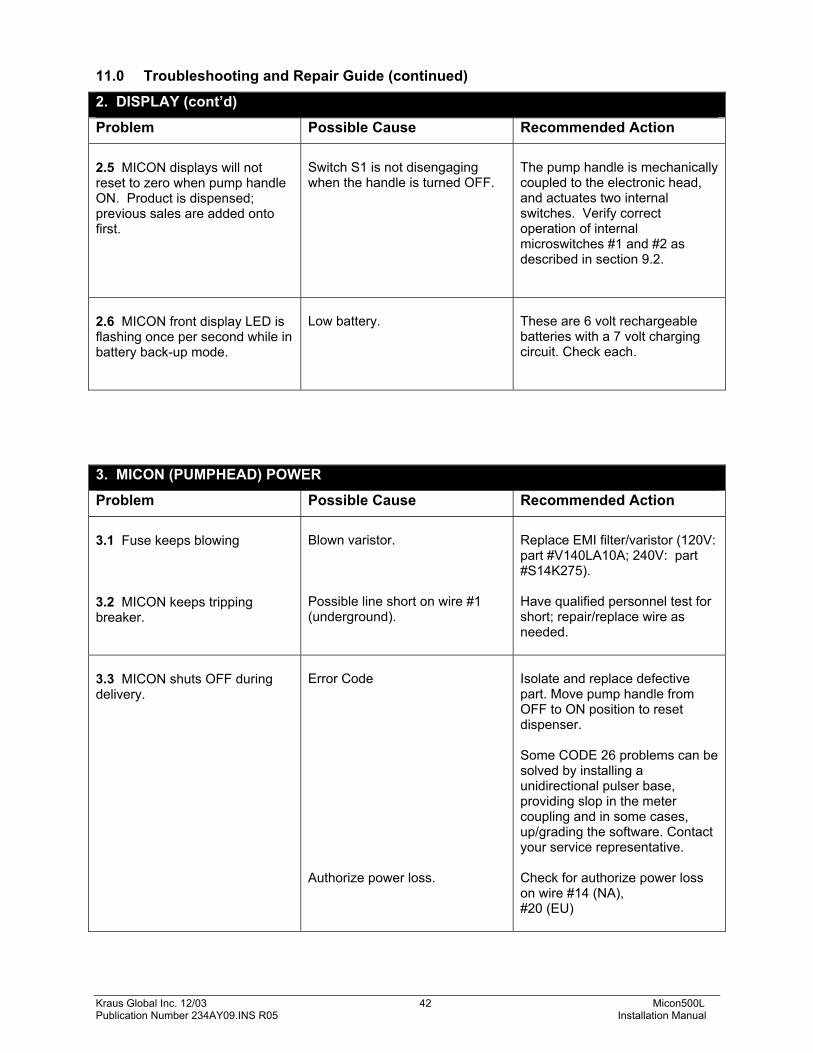
11.0 Troubleshooting and Repair Guide (continued)
2. DISPLAY (cont’d)
Problem Possible Cause Recommended Action 2.5 MICON displays will not reset to zero when pump handle ON. Product is dispensed; previous sales are added onto first.
Switch S1 is not disengaging when the handle is turned OFF.
The pump handle is mechanically coupled to the electronic head, and actuates two internal switches. Verify correct operation of internal microswitches #1 and #2 as described in section 9.2.
2.6 MICON front display LED is flashing once per second while in battery back-up mode.
Low battery.
These are 6 volt rechargeable batteries with a 7 volt charging circuit. Check each.
3. MICON (PUMPHEAD) POWER
Problem Possible Cause Recommended Action 3.1 Fuse keeps blowing 3.2 MICON keeps tripping breaker.
Blown varistor. Possible line short on wire #1 (underground).
Replace EMI filter/varistor (120V: part #V140LA10A; 240V: part #S14K275). Have qualified personnel test for short; repair/replace wire as needed.
3.3 MICON shuts OFF during delivery.
Error Code Authorize power loss.
Isolate and replace defective part. Move pump handle from OFF to ON position to reset dispenser. Some CODE 26 problems can be solved by installing a unidirectional pulser base, providing slop in the meter coupling and in some cases, up/grading the software. Contact your service representative. Check for authorize power loss on wire #14 (NA), #20 (EU)
Kraus Global Inc. 12/03 43 Micon500L Publication Number 234AY09.INS R05 Installation Manual
11.0 Troubleshooting and Repair Guide (continued)
3. MICON (PUMPHEAD) POWER (cont’d)
Problem Possible Cause Recommended Action 3.4 MICON shuts OFF at beginning of delivery.
Reversed pulser lines. (Observe the PPU (price per unit) display in the MICON. If fault code CO30 displays, problem is excessive reverse counts, caused by backward connected pulser. No pulses being generated (pulser). (Observe the PPU [price per unit] display in the MICON. If fault code CO26 displays, problem is missing or disconnected pulser.) Observe the PPU (price per unit) display in the MICON. If fault code CO27 displays, problem is pulser buffer overflow fault.
Locate the 4 wire harness between the pulser and the Micon. Connect WHITE wire where YELLOW located; connect YELLOW wire where WHITE located. Check harness lead electrical connections. Micro motion meter may be programmed for higher ppu than MICON rating. Ensure Micro-Motion meter and MICON flow rates are compatible.
Kraus Global Inc. 12/03 44 Micon500L Publication Number 234AY09.INS R05 Installation Manual
11.0 Troubleshooting and Repair Guide (continued)
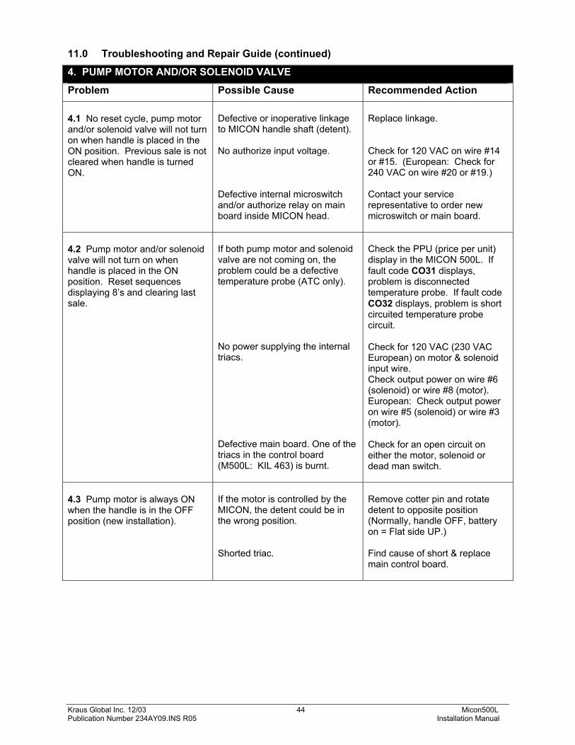
4. PUMP MOTOR AND/OR SOLENOID VALVE
Problem Possible Cause Recommended Action 4.1 No reset cycle, pump motor and/or solenoid valve will not turn on when handle is placed in the ON position. Previous sale is not cleared when handle is turned ON.
Defective or inoperative linkage to MICON handle shaft (detent). No authorize input voltage. Defective internal microswitch and/or authorize relay on main board inside MICON head.
Replace linkage. Check for 120 VAC on wire #14 or #15. (European: Check for 240 VAC on wire #20 or #19.) Contact your service representative to order new microswitch or main board.
4.2 Pump motor and/or solenoid valve will not turn on when handle is placed in the ON position. Reset sequences displaying 8’s and clearing last sale.
If both pump motor and solenoid valve are not coming on, the problem could be a defective temperature probe (ATC only). No power supplying the internal triacs. Defective main board. One of the triacs in the control board (M500L: KIL 463) is burnt.
Check the PPU (price per unit) display in the MICON 500L. If fault code CO31 displays, problem is disconnected temperature probe. If fault code CO32 displays, problem is short circuited temperature probe circuit. Check for 120 VAC (230 VAC European) on motor & solenoid input wire. Check output power on wire #6 (solenoid) or wire #8 (motor). European: Check output power on wire #5 (solenoid) or wire #3 (motor). Check for an open circuit on either the motor, solenoid or dead man switch.
4.3 Pump motor is always ON when the handle is in the OFF position (new installation).
If the motor is controlled by the MICON, the detent could be in the wrong position. Shorted triac.
Remove cotter pin and rotate detent to opposite position (Normally, handle OFF, battery on = Flat side UP.) Find cause of short & replace main control board.
Kraus Global Inc. 12/03 45 Micon500L Publication Number 234AY09.INS R05 Installation Manual
11.0 Troubleshooting and Repair Guide (continued)
5. REGISTRATION
Problem Possible Cause Recommended Action 5.1 Product can be dispensed but it’s not registering on either the mechanical totalizer or electronic display.
Inoperative drive to MICON input shaft. Stripped or loose gears on MICON base. This only occurs when direct drive meters are used (i.e., those that do not use a remote pulser). Broken coupling between the meter and electronic register.
5.4 MICON is losing its price settings and totals.
Low battery.
It is a 6.0 VDC rechargeable battery with a 7.0 VDC charging circuit. If battery does not recharge, contact your service representative.
5.5 MICON totals are jumping or the price is changing by itself.
Low battery. Defective KIL 463 control board (M500L).
It is a 6.0 VDC rechargeable battery with a 7.0 VDC charging circuit. If battery does not recharge, contact your service representative. Contact your service representative to order new board.
After correcting source of error, always turn dispenser handle switch OFF, then ON.
REMINDER !
Kraus Global Inc. 12/03 46 Micon500L Publication Number 234AY09.INS R05 Installation Manual