PDHonline Course E294 (3 PDH) Micro-Combined Heat and Power Systems 2012 Instructor: Lee Layton, PE PDH Online | PDH Center 5272 Meadow Estates Drive Fairfax, VA 22030-6658 Phone & Fax: 703-988-0088 www.PDHonline.org www.PDHcenter.com An Approved Continuing Education Provider
Introduction A product that is just emerging in the residential sector is micro-combined heat and power systems. A micro-combined heat and power system (m-CHP) is a power source that will simultaneously generate useful heat, cooling effects, and power for residential or small commercial applications. Micro-CHP systems are generally considered to be systems of 15 kW electrical demand or smaller. Combined heat and power (CHP) generation systems are not new. In fact, they have been around for well over a century. In the late 1800’s steam was the prime mover for mechanical equipment in industrial plants and the steam was also used to generate electricity for lighting. In the early 1900’s steam driven equipment was replaced with electric motors, but combined heat and power systems, also known as co-generation systems, continued to be used in industrial plants and, in fact, co-generation is still a popular concept for industry. Building on the success of co-generation in the industrial sector, products are now appearing in the residential sector that will supply both the heat and power needs of a residential home. The components of a m-CHP system include a prime mover, a heat exchanger for hot water, a heat exchanger for building heat, an electrical generator, and maybe an absorption chiller, and a desiccant dehumidifier. The prime mover may be a reciprocating engine, turbine, fuel cell, or some other type of energy source that can be used to produce electricity. The waste heat from the prime mover is then used to ‘fuel’ the other components of the m-CHP system. A major distinction between industrial CHP systems and m-CHP systems is that industrial CHP systems generate electricity and heat is the useful by-product for other functions. However, with a m-CHP system, the systems are primarily driven by the heat demand of the home and electricity is a by-product. This difference is significant, because if there is not a major heat load, then the system cannot economically generate a useful amount of electricity. This may mean that m-CHP systems will only find a niche market in predominately cold climates. In this course, we will look at the various components of a micro-combined heat and power system including the prime movers that are the back-bone of the system, heat exchangers, absorption chillers, and desiccant dehumidifiers. But, first let’s begin with an overview of m-CHP systems.
II. Micro-Combined Heat & Power Systems When considering m-CHP systems a logical question is “how can m-CHP units that use gas fired prime movers be more efficient than central station electricity generation?” In fact, a m-CHP prime mover is generally much less efficient than a central station generator that uses coal, nuclear, or even gas to fire its boilers. Central station units lose about 50% of their energy in waste heat during production and the power still must be transmitted to the load center where the end user is located. To transport the power generated by a central station generator, the voltage must be increased for transmission to the distant load center. Losses occur during this transformation. Furthermore, energy is loss in the transportation of electrical energy across the high voltage transmission lines. Once the power is transported to a general area the voltage must be reduced and then transported across lower voltage distribution lines to residential neighborhoods where the voltage is again reduced to levels suitable for use within a home. Each of the voltage transformations and each power line that distributes the power consume some of the power generated by the central station generator. The end result is that only about 45% of the energy produced is actually available for consumption at the end user. Figure 1 shows a typical electric power system.
Contrast this with a m-CHP system where the electricity is generated right at the end user and the waste heat from the unit is utilized for space heating and domestic hot water. Since the m-CHP avoids transportation losses, the end user efficiency can approach 75% - if the waste heat can be fully utilized. Figure 2 shown below is a representation of the energy transport from a natural gas field to the end use in the home. Approximately 10% of the energy is consumed in retrieving the natural gas and another 20% is lost in processing and delivery of the gas. This leaves 70% of the energy available for the m-CHP system.
With a typical m-CHP system about 70% of the energy (e.g. natural gas) delivered to the home is converted into useful heat for space and water heating. Approximately 20% of the energy is converted into electricity and the remaining 10% is lost as waste heat. These units compare favorably with a conventional natural gas central heating system where 80% of the energy is converted into heat and the remaining 20% is lost as waste heat. The following chart shows a breakdown of energy consumption in the typical residential home in the United States. From the chart we can see that heating is the largest energy consumer in the home at 62% of the total energy use. The next largest consumer is cooling load, which accounts for 23% of the home’s energy use. Lights and other miscellaneous appliances account for about 10% followed by cooking, which is about 5% of a typical home’s energy consumption. Figure 4 shown below is a typical application of m-CHP. In this example natural gas is supplied to the m-CHP system. The system generates electricity which is fed into the main AC panel in the house (shown as the green line on the diagram). Waste heat from the m-CHP system generates hot water, which is supplied to heating radiators throughout the house and to the hot water storage tank (hot water is shown in red on the diagram). Hot water is also supplied to the absorption chiller, which provides cooling in the house. The remaining waste heat is exhausted through the flue vent.
For another view of a m-CHP, look at the schematic in Figure 5. As you can see, the prime mover turns an electrical generator to generate electricity. In the process, the prime mover will generate heat from the exhaust gases and from the cooling system installed on the prime mover.
The waste heat from the prime mover is used to generate hot water. The hot water is then fed into heating radiators to heat the home and the hot water is fed into a hot water storage tank for domestic hot water needs. The hot water can also be used to operate an absorption chiller for cooling and a desiccant dehumidifier. There are several options for the prime mover in the m-CHP system. The following are the most promising methods of driving a m-CHP system,
Some of the prime movers, reciprocating engines for instance, not only generate hot exhaust gases, but also generate waste heat from the engine’s cooling systems. Others, such as fuel cells, generate hot water through a chemical reaction process. Recent advances in engine technology have improved the economic viability of m-CHP systems. We will look at each of these technologies in detail in the next section. Heat exchangers allow for the recovery of the waste heat from the prime mover to be turned into useful energy. Heat exchangers take the hot exhaust gases from an engine and transfer the heat energy to another air source that can then be ducted into a building for space heating, much like a traditional gas furnace. Some heat exchangers transfer the waste heat to a liquid to produce hot water. In some cases the waste heat from engine cooling systems can be used to transfer heat energy. Absorption chillers provide cooling by using heat. Unlike conventional electric chillers, which use mechanical energy in a vapor compression process to provide refrigeration, absorption chillers primarily use waste heat energy with limited mechanical energy for pumping. An absorption chiller transfers thermal energy from the heat source to the heat sink through an absorbent fluid and a refrigerant. The absorption chiller accomplishes its refrigeration effect by absorbing and then releasing water vapor into and out of a special solution. The process begins as heat is applied at the generator and water vapor is driven off to a condenser. The cooled water vapor then passes through an expansion valve where the pressure reduces. The low-pressure water vapor then enters an evaporator, where ambient heat is added from a load and the actual cooling takes place. The heated, low-pressure vapor returns to the absorber, where it recombines with the solution and becomes a low-pressure liquid. This low-pressure solution is pumped to a higher pressure and into the generator to repeat the process.
Absorption chillers meet the sensible cooling load of a building, but the latent load is met by reducing the relative humidity of the air. Ideally, the relative humidity in a building should be below 60%. A desiccant dehumidifier is a device that employs a desiccant material to produce a dehumidification effect. Desiccant materials directly absorb moisture from the air. The moisture content in a desiccant material is a function of the relative humidity of the surrounding air. A desiccant dehumidifier works by exposing the desiccant material to a high relative humidity air stream, allowing it to attract and retain some of the water vapor, which reduces the humidity of the air stream. Waste heat is then used to heat an air stream to pass through the desiccant material to draw out the retained moisture and regenerate the desiccant for another cycle. A concern when attempting to transfer the CHP technology from industry to micro-CHP systems for residential applications is the difference in the electric load cycles. In industrial plants, the base electric load is fairly constant and typically runs for more than 75% of the hours during the year. In a residential application, the heat load may only be present for 30-40% of the hours in the year and without the heat load the m-CHP system will not be efficient to operate to just meet the electrical demand. Residential electrical demand is also much more variable than industrial loads. Average residential loads range from about one to 1.5 kW, but will have peaks in excess of 10 kW. An electric hair dryer alone will have a peak demand of 1.5 kW. Therefore, m-CHP systems can only meet a portion of the electric load of a residential application and must be supplemented with grid connected power. Regardless of the economic benefit, there may be an environmental benefit to m-CHP systems in some applications. Due to cold climates and high energy cost m-CHP systems are beginning to appear in Japan and Europe. The US market has not seen any appreciable use of m-CHP yet, but the market is expected to grow – especially in northern climates.
Sensible cooling accounts for the interior heat gain due to heat conduction, convection, and radiation from the exterior into the interior, and from occupants and appliances. Latent cooling load is created by moisture in the air, including from outside air infiltration and that from indoor sources such as occupants, plants, cooking, showering, etc.
III. Primer Movers As previously mentioned, the most popular options for m-CHP prime movers are reciprocating engines, Stirling engines, micro-turbines, Rankine cycle engines, and fuel cells. The basic operation and the advantages and disadvantages of these units are described below in more detail.
Reciprocating Engines Reciprocating engines, also known as internal combustion engines, require fuel, air, compression, and a combustion source to function. They make up the largest share of the small power generation market and can be used in a variety of applications due to their small size, low unit costs, and useful thermal output. Reciprocating engines fall into one of two categories depending on the ignition source: spark ignition (SI), typically fueled by gasoline or natural gas; or compression ignition (CI), which are typically fueled by diesel oil. Reciprocating engines also are categorized by the number of revolutions it takes to complete a combustion cycle. A two-stroke engine completes its combustion cycle in one revolution, and a four-stroke engine completes the combustion process in two revolutions. The four-stroke SI engine has an intake, compression, power, and exhaust cycle. In the intake stroke, as the piston moves downward in its cylinder, the intake valve opens and the upper portion of the cylinder fills with fuel and air. When the piston returns upward in the compression cycle, the spark plug fires and ignites the fuel/air mixture. This controlled combustion forces the piston down in the power stroke, turning the crankshaft and producing useful shaft power. Finally, the piston moves up again, exhausting the burnt fuel and air in the exhaust stroke. The four-stroke CI engine operates in a similar manner, except diesel fuel and air ignite when the piston compresses the mixture to a critical pressure. At this pressure, no spark or ignition system is needed because the mixture ignites spontaneously, providing the energy to push the piston down in the power stroke. The two-stroke engine, whether SI or CI, has a higher power density, because it requires half as many crankshaft revolutions to produce power. However, two-stroke engines let more fuel pass through, resulting in higher hydrocarbon emissions in the form of unburned fuel. Waste heat from a reciprocating engine can produce 100C hot water and is responsible for approximately 30% of the energy input from the fuel source. The engine exhaust is capable of producing hot air temperatures of up to 650C and account for another 30% of the energy input. With friction losses of 5% the base efficiency of the engine is about 35%. With both coolant and exhaust heat recovery, and considering the work produced by the engine itself, a reciprocating engine can recover up to 70-80% of the fuel source energy.
Reciprocating engines can be installed to accommodate baseload, peaking, emergency or standby power applications. Commercially available engines range in size from 10 kW to more than 7 MW, making them suitable for many distributed-power applications. Utilities can install engines to provide baseload or peak shaving power. However, the most promising markets for reciprocating engines are on-site for residential m-CHP systems. With fast start-up times, reciprocating engines can play integral backup roles in many building energy systems. On-site reciprocating engines become even more attractive in regions with high electric rates. When properly treated, the engines can run on fuel generated by waste treatment (methane) and other biofuels. By using the recuperators that capture and return waste exhaust heat, reciprocating engines can be used in combined heat and power (CHP) systems to achieve energy efficiency levels approaching 80%. In fact, reciprocating engines make up a large portion of the CHP or cogeneration market. Commercially available engines have efficiencies of around 35% and yield NOx emissions of 0.5-2.0 grams per horsepower hour (hp-hr) for lean-burn natural gas engines. The installed cost for a reciprocating engine ranges from between $700 and $1,400 per kW depending on size and whether the unit is for a straight generation or cogeneration application. Operating and maintenance costs range from $0.008 to $0.018/kWh. Exhaust temperature for most reciprocating engines is 375-650C in non-CHP mode and 175-250C in a CHP system after heat recovery. Noise levels with sound enclosures are typically between 70-80 dB. The reciprocating-engine systems have several major components: Fuel storage, handling, and conditioning, prime mover, emission controls, waste recovery and radiators, and electrical switchgear. Reciprocating engines can have a substantial maintenance costs and require regular routine maintenance. Diesel engines are heavier and noisier than gasoline engines, but they can be more powerful and more fuel efficient. The advantages of reciprocating engines includes quick start times, low capital costs, mature technology, fuel flexible, simple operation, minimum auxiliary equipment required. However, they are noisy, require frequent maintenance, and generate significant emissions. It is anticipated that future reciprocating engines will achieve NOx levels of 0.1 h/hp-hr and will have fuel-to-electricity conversion efficiencies of 50%. These units will be capable of handling a wide variety of fuels from natural gas, propane, to biogas and hydrogen. Stirling Engines A Stirling engine is an external combustion engine which is in contrast to the more conventional internal combustion engine. It is a closed-cycle piston heat engine. The term closed-cycle means that the working gas is permanently contained within the cylinder, unlike the open-cycle internal combustion engine, which vents the working fluid to the atmosphere. It operates through the use of an external heat source and an external heat sink, each maintained within a limited temperature range, and having a sufficiently large temperature difference between them.
In the conversion of heat into mechanical work, Stirling engines can achieve the highest efficiency of any heat engine, limited only by the properties of the working gas and engine materials, such as friction, thermal conductivity, etc. The engines can theoretically run on any heat source of sufficient quality, including solar, chemical and nuclear. In contrast to internal combustion engines, Stirling engines are usually more energy efficient, quieter, and more reliable with lower-maintenance requirements. Their economics are characterized with have high capital costs and low operating costs. They tend to be larger and heavier than an equivalent capacity internal combustion engine. In recent years, the advantages of Stirling engines have become increasingly significant, given the general rise in energy costs, energy shortages and environmental concerns such as climate change. Another potentially useful characteristic of the Stirling engine is that it can function as a heat pump and can be used in m-CHP applications. Since the Stirling engine is a closed cycle, it contains a fixed quantity of gas. This "working fluid" is generally air, hydrogen or helium. In normal operation, the engine is sealed and no gas enters or leaves the engine. No valves are required, unlike other types of piston engines. Like most heat-engines it cycles through four main processes: cooling, compression, heating and expansion. This is accomplished by moving the gas back and forth between hot and cold heat exchangers. The hot heat exchanger is in thermal contact with an external heat source and the cold heat exchanger being in thermal contact with an external heat sink. A change in gas temperature will cause a corresponding change in gas pressure, while the motion of the piston causes the gas to be alternately expanded and compressed. The gas follows the behavior described by the gas laws which describe how the pressure, temperature and volume of the gas are related. When the gas is heated, because it is in a sealed chamber, the pressure rises and acts on the power piston to produce a power stroke. When the gas is cooled the pressure drops and this means that less work needs to be done by the piston to compress the gas on the return stroke, thus yielding a net power output. Therefore, the Stirling engine uses the potential energy difference between its hot end and cold end to establish a cycle of a fixed amount of gas expanding and contracting within the engine, thus converting a temperature difference across the machine into mechanical power. The greater the temperature difference between the hot and cold sources, the greater the power produced, and thus, the lower the efficiency required for the engine to run. Some Stirling engines use a regenerator. The regenerator is a reverse flow heat exchanger, which is used to improve thermal efficiency. Thermal regeneration improves the overall efficiency and power produced by a Stirling engine. A regenerator is not always used on low temperature difference (LTD) designs, but is almost always used on high temperature difference (HTD) Stirling engines.
The regenerator is located in the path of the gas between the hot and cold heat exchangers. As the gas cycles between the hot and cold spaces, over 90% of its heat is temporarily transferred to and from the regenerator. The regenerator essentially recycles unused heat, and thus reduces the heat flow requirements of the hot and cold heat exchangers.
There are three types of Stirling engines: The Alpha, Beta, and Gamma. The Alpha type engine relies on interconnecting the power pistons of multiple cylinders to move the working gas, with the cylinders held at different temperatures. The Beta and Gamma type Stirling engines use a displacer piston to move the working gas back and forth between hot and cold heat exchangers in the same cylinder. The following is an explanation of how an Alpha type Stirling engine operates. See Figure 6 for a diagram of an Alpha type Stirling engine. An alpha Stirling contains two separate power pistons in separate cylinders. One cylinder is heated by an external heat source and the other is cooled by an external cooling source. The gas chambers of the two cylinders are connected, and the pistons are connected to each other mechanically by a linkage that determines how they will move in relation to one another.
There are four parts to the Stirling cycle. In the first cycle, heat is added to the gas inside the heated cylinder (the cylinder on the left in the drawing), causing pressure to build. This forces the piston to move to the right. This is the part of the Stirling cycle that does work. In the next cycle, the “hot” piston moves left while the “cold” piston moves down. This pushes the hot gas into the cooled cylinder, which quickly cools the gas to the temperature of the cooling source, lowering its pressure. This makes it easier to compress the gas in the next part of the cycle. In the third cycle, the piston in the cooled cylinder starts to compress the gas. (Heat generated by this compression is removed by the cooling source.) In the final stage the “cold” piston moves up while the “hot” piston moves to the right. This forces the gas into the heated cylinder, where it quickly heats up, building pressure, at which point the cycle repeats. (The crankshaft’s inertia helps move the pistons through their non-working cycles.)
A beta Stirling has a single power piston arranged within the same cylinder on the same shaft as a displacer piston. The displacer piston is a loose fit and does not extract any power from the expanding gas but only serves to shuttle the working gas from the hot heat exchanger to the cold heat exchanger. When the working gas is pushed to the hot end of the cylinder it expands and pushes the power piston. When it is pushed to the cold end of the cylinder it contracts and the momentum of the machine, usually enhanced by a flywheel, pushes the power piston the other way to compress the gas. A gamma Stirling is simply a beta Stirling in which the power piston is mounted in a separate cylinder alongside the displacer piston cylinder, but is still connected to the same flywheel. The gas in the two cylinders can flow freely between them but remains a single body. This configuration produces a lower compression ratio but is mechanically simpler and often used in multi-cylinder Stirling engines.
Stirling engines have efficiencies of 15-30%, without heat recovery. Typical operating temperatures range from 650C to 800C with electrical engine conversion efficiencies of around 40%. These high operating temperatures can be used to provide high quality waste heat. Stirling engines have the following advantages,
1. Waste heat is relatively easy to recover. 2. They can run directly on any available heat source. 3. A continuous combustion process can be used to supply heat, so most types of emissions
can be greatly reduced. 4. Require very little maintenance. 5. Simple design.
The disadvantages of Stirlings include,
1. Stirling engines that run on small temperature differentials are quite large for the amount of power that they produce.
2. A Stirling engine cannot start instantly; it literally needs to "warm up". 3. It is difficult to control the power output of a Stirling engine. 4. Stirling engines are very expensive.
Micro-turbines Microturbines are small combustion turbines of a size comparable to a refrigerator and with outputs of 30 kW to 400 kW. They are used for stationary energy generation applications at sites with space limitations for power production. They are fuel-flexible machines that can run on natural gas, biogas, propane, butane, diesel, and kerosene. Microturbines have few moving parts, high efficiency, low emissions, low electricity costs, and waste heat utilization opportunities; and are lightweight and compact in size. Waste heat recovery can be used in m-CHP systems to achieve energy efficiency levels greater than 80%. Microturbines consist of a compressor, combustor, turbine, alternator, recuperator, and generator. Microturbines are classified by the physical arrangement of the component parts: single shaft or two-shaft, simple cycle or recuperated, inter-cooled, and reheat. The machines generally operate at more than 40,000 rpm, while some machines operate at more than 100,000 rpm. A single shaft is the more common design, because it is simpler and less expensive to build. Conversely, the split shaft is necessary for machine-drive applications, which do not require an inverter to change the frequency of the AC power. Efficiency gains can be achieved with greater use of materials like ceramics, which perform well at higher engine-operating temperatures.
In simple cycle, microturbines heated, compressed air is mixed with fuel and burned under constant pressure conditions. The resulting hot gas is allowed to expand through a turbine to perform work. Simple-cycle microturbines have a lower cost, higher reliability, and more heat available for CHP applications than recuperated units. Recuperated units use a heat exchanger that recovers some of the heat from an exhaust stream and transfers it to the incoming air stream. The preheated air is then used in the combustion process. If the air is preheated, less fuel is necessary to raise its temperature to the required level at the turbine inlet. Recuperated units have a higher efficiency and thermal-to-electric ratio than un-recuperated units, and yield 30%-40% fuel savings from preheating.
or. the turbine is fed back through the recuperator to preheat the incoming
ombustion air.
s
or other 0C.
owever, with a recuperator, the exhaust gas temperature may be less than 300C.
ributed energy resources such as energy-storage devices and thermally
ctivated technologies.
stallation cost averages $2,200 per kW for power only systems and $2,600 for CHP systems.
Following Figure 7, air enters the compressor and is pre-heated for combustion in the recuperator. The air mixes with the fuel in the combustor, and the combusted air/fuel mixture expands through the turbine. The turbine shaft drives both the compressor and the generatThe exhaust fromc The waste heat from a microturbine is primarily in the form of hot exhaust gases. This heat isuitable for powering a steam generator, building heat, thermal storage devices, or use in an absorption cooling system. The recuperator will limit some of the waste heat available fapplications. In non-recuperator systems, the exhaust gas temperature is around 60H Microturbines can be used in a wide range of applications in the commercial, industrial, and institutional sectors. Microturbines can be used for backup power, baseload power, premium power, remote power, grid support, peak shaving, cooling and heating power. Microturbines canbe paired with other dista The typical 30 kW unit package cost averages $1,100 per kW. For gas-fired microturbines, the in
atch the load profile. 4. They are generally too large for residential for m-CHP systems.
missions of less than 7ppm (using natural gas), and a service life of over 45,000 hours.
ankine Cycle Engines
r low
stics. They are just beginning to be considered as a potential source for m-CHP ystems.
he
ter, though other liquids can also be used.
ess.
id is in
t
p
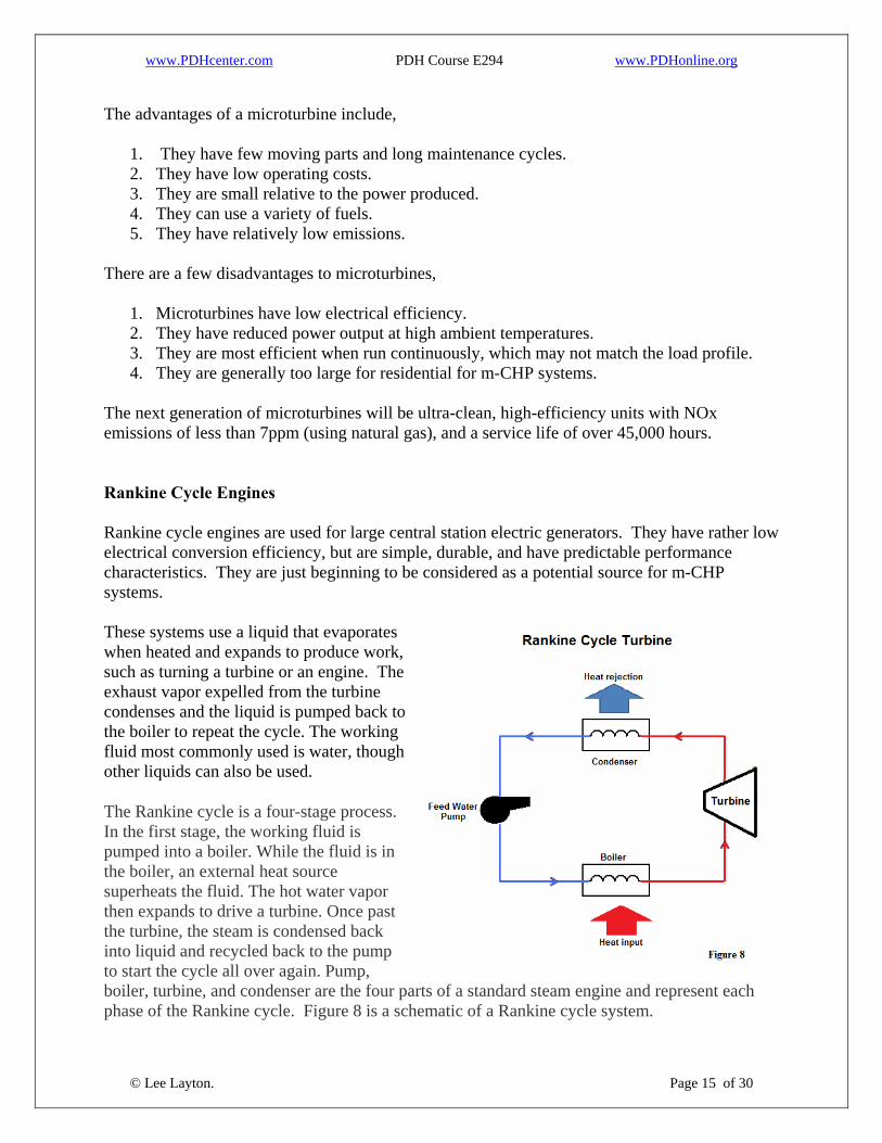
epresent each phase of the Rankine cycle. Figure 8 is a schematic of a Rankine cycle system.
1. They have few moving parts an2. They have low operating costs. 3. They are small relative to the po4. They can use a variety of fuels.
T
1. Microturbines have low electrical efficiency. 2. They have reduced power output at high ambient temperatures. 3. They are most efficient when run continuously, which may not m
The next generation of microturbines will be ultra-clean, high-efficiency units with NOx e R Rankine cycle engines are used for large central station electric generators. They have ratheelectrical conversion efficiency, but are simple, durable, and have predictable performancecharacteris These systems use a liquid that evaporates when heated and expands to produce work, such as turning a turbine or an engine. Texhaust vapor expelled from the turbine condenses and the liquid is pumped back tothe boiler to repeat the cycle. The working fluid most commonly used is wa
The Rankine cycle is a four-stage procIn the first stage, the working fluid is pumped into a boiler. While the fluthe boiler, an external heat source superheats the fluid. The hot water vapor then expands to drive a turbine. Once pasthe turbine, the steam is condensed back into liquid and recycled back to the pumto start the cycle all over again. Pump, boiler, turbine, and condenser are the four parts of a standard steam engine and r
In comparison to gas turbines where a significant fraction of the work generated by the turbine is required to drive the compressor, limiting net work output and efficiency, a Rankine cycle requires very little power for ancillary needs. By condensing the steam to water, the work required by the pump will only consume approximately 1% of the turbine power resulting in a much higher efficiency. As liquids are far less compressible they require only a fraction of the energy needed to compress a gas to the same pressure.
The efficiency of a Rankine cycle is usually limited by the working fluid. Without the pressure going super critical the operating temperature range is quite small; turbine entry temperature is typically 565C and condenser temperatures are around 30C. This gives a theoretical efficiency of around 63% compared with an actual efficiency of 42% for a modern coal fired power station. The working fluid in a Rankine cycle follows a closed loop and is re-used constantly. There are four processes in the Rankine cycle, each changing the state of the working fluid. See the drawing in figure 8 above. In the first step the working fluid is pumped from low to high pressure, as the fluid is a liquid at this stage the pump requires little input energy. Next, the high pressure liquid enters a boiler where it is heated at constant pressure by an external heat source to become a dry saturated vapor. In a m-CHP system, the heat source is likely natural gas. Passing through the boiler the dry saturated vapor expands through a turbine generating power output usually orders of magnitude greater than the power required by the pump. This decreases the temperature and pressure of the vapor and some condensation may occur. In the final step, the wet vapor enters a condenser where it is cooled at a constant low pressure to become a saturated liquid. It is fully condensed to a liquid to minimize the work required by the pump. In an ideal Rankine cycle, the compression by the pump and the expansion in the turbine would be completely reversible and there would be no losses in the conversion. Of course, in the real world the process does generate losses, which increases the power required by the pump and decreases the power generated by the turbine. The efficiency of the steam turbine will be limited by water droplet formation. As the water condenses, water droplets hit the turbine blades at high speed causing pitting and erosion, gradually decreasing the efficiency of the turbine. The easiest way to overcome this problem is by superheating the steam. Two main variations of the basic Rankine cycle: Rankine cycle with reheat and Regenerative Rankine cycles.
A Rankine cycle with reheat uses two turbines in series. The first accepts vapor from the boiler at high pressure. After the vapor has passed through the first turbine, it re-enters the boiler and is
reheated before passing through a second, lower pressure turbine. This prevents the vapor from condensing during its expansion which can seriously damage the turbine blades, and improves the efficiency of the cycle. The other variation is the regenerative Rankine cycle. With this process, the working fluid is heated by steam tapped from the hot portion of the cycle after emerging from the condenser. This increases the average temperature of heat addition which in turn increases the thermodynamic efficiency of the cycle. Another type of Rankine cycle is the Organic Rankine Cycle (ORC). These systems use some type of organic chemical as the working fluid instead of water. Typical refrigerants, such as Freon, are frequently used in ORC systems. ORC systems allow the Rankine cycle to have higher pressures or volumes as the working fluid goes from the expansion through the turbine to condensation. The ORC systems also allow the turbines to run at slower speeds. ORC systems are the most likely form of Rankine cycle for m-CHP systems. The advantages of applying Rankine cycle systems to m-CHP is that the working fluid is a liquid and is easy to manage, the systems are relatively simple and reliable, and since it is a closed loop system with a condenser, heat recovery should be straightforward. Fuel Cells A fuel cell is an electrochemical energy conversion device that converts hydrogen and oxygen into electricity and water. This unique process is practically silent, nearly eliminates emissions, and has no moving parts.
Similar to a battery, fuel cells have an anode and a cathode separated by an electrolyte. Hydrogen enters the anode and air (oxygen) enters the cathode. The hydrogen and oxygen are separated into ions and electrons, in the presence of a catalyst. Ions are conducted through the electrolyte
while the electrons flow through the anode and the cathode via an external circuit. The current produced can be utilized for electricity. The ions and electrons then recombine, with water and heat as the only byproducts. Fuel cell systems typically consist of a fuel processor, fuel cell stack, and power conditioner. The fuel processor, or reformer, converts hydrocarbon fuels to a mixture of hydrogen-rich gases and, depending on the type of fuel cell, can remove contaminants to provide pure hydrogen. The fuel cell stack is where the hydrogen and oxygen electrochemically combine to produce electricity. The electricity produced is direct current (DC) and the power conditioner converts the DC electricity to alternating current (AC) electricity, for which most of the end-use technologies are designed. As a hydrogen infrastructure emerges, the need for the reformer will disappear as pure hydrogen will be available near point of use. The primary fuel cell technologies under development are Phosphoric acid fuel cells, Polymer electrolyte membrane, solid oxide fuel cells, Direct-methanol fuel cell, molten carbonate fuel cell, alkaline fuel cell, and regenerative fuel cells. Each is briefly explained below. Phosphoric acid fuel cell (PAFC) -A phosphoric acid fuel cell (PAFC) consists of an anode and a cathode made of a finely dispersed platinum catalyst on carbon paper, and a silicon carbide matrix that holds the phosphoric acid electrolyte. These fuel cells operate at 190-210C and achieve 35 to 45% fuel-to-electricity efficiencies and have commercially-validated reliabilities of 90-95%. This is the most commercially developed type of fuel cell and is being used in hotels, hospitals, and office buildings. Health hazards of phosphoric acid may limit commercialization. Polymer electrolyte membrane (PEM) fuel cell - The polymer electrolyte membrane (PEM) fuel cell uses a thin fluorinated plastic sheet that allows hydrogen ions (protons) to pass through it. The membrane is coated on both sides with highly dispersed metal alloy particles (mostly platinum) that are active catalysts. Proton Exchange Membrane Fuel Cells (PEMFCs) operate at relatively low temperatures of 70-100C have high-power density, can vary their output quickly to meet shifts in power demand, however, they are not well suited to m-CHP systems because of their low operating temperatures. Solid oxide fuel cells (SOFC) – These units operate at temperatures up to 1,000C. A solid oxide system usually uses a hard ceramic material such as a thin layer of zirconium oxide instead of a liquid electrolyte. The cathode is lanthanum manganate and the anode is nickel-zirconia. The solid-state ceramic construction of SOFC’s enables high temperatures, allows more flexibility in fuel choice, and contributes to stability and reliability. SOFCs are capable of fuel-to-electricity efficiencies of 45% to 55% and total system thermal efficiencies up to 85% in combined-cycle applications. This is a promising option for high-powered applications, including m-CHP systems.
Direct-methanol fuel cell (DMFC) - A relatively new member of the fuel cell family, the direct-methanol fuel cell (DMFC) is similar to the PEM cell in that it uses a polymer membrane as an electrolyte. However, a catalyst on the DMFC anode draws hydrogen from liquid methanol, eliminating the need for a fuel reformer.
Molten carbonate fuel cell (MCFC) - The molten carbonate fuel cell uses a molten carbonate salt as the electrolyte. MCFC technology has the potential to reach fuel-to-electricity efficiencies of 45% to 60%. Operating temperatures for MCFCs are around 650C, which allows total system thermal efficiencies up to 50% in combined-cycle applications. MCFCs have been operated on hydrogen, carbon monoxide, natural gas, propane, landfill gas, marine diesel, and simulated coal gasification products and are good candidates for m-CHP systems. Alkaline fuel cell (AFC) -The alkaline fuel cell uses an alkaline electrolyte such as potassium hydroxide. Originally used by NASA on missions, it is now finding applications in hydrogen-powered vehicles. AFCs contain a potassium hydroxide (KOH) solution as the electrolyte and operate at temperatures between 60 and 260C. The fuel supplied to an AFC must be pure hydrogen. Carbon monoxide poisons an AFC, and carbon dioxide (even the small amount in the air) reacts with the electrolyte to form potassium carbonate. AFC’s are a special application fuel cell and are not well suited for the residential m-CHP market. Regenerative Fuel Cells - This special class of fuel cells produces electricity from hydrogen and oxygen, but can be reversed and powered with electricity to produce hydrogen and oxygen. Fuel cell systems can be sized for grid-connected applications or customer-sited applications in residential, commercial, and industrial facilities. Depending on the type of fuel cell, useful heat can be captured and used in a m-CHP system. The following table shows the status of the various types of fuel cell designs.
It is expected that high-temperature natural gas-fueled MCFC’s and SOFC’s will be available soon that will cost $1,000 - $1,500 per kW, have efficiencies of 60%, have ultra-low emissions,
and a 40,000 hour stack life. Other efforts include raising the operating temperature of the PEM fuel cell for building, cooling, heating, and power applications and improve reformer technologies to extract hydrogen from a variety of fuels, including natural gas, propane, and methanol.
Fuel cells may find a use in m-CHP systems. They are quite and convert chemical energy directly into electricity without a combustion process and the associated mechanical losses of an engine type system. The main disadvantages of fuel cells are capital costs, and lack of commercially available products.
IV. Heat Recovery A key component to the success of micro-combined heat and power systems is heat recovery. Because prime movers give up 40% - 70% of their available energy as waste heat, m-CHP systems can make use of this energy, which will increase the overall thermal efficiency of a system. Heat recovery converts waste heat to useful energy and is primarily accomplished through the use of heat exchangers. The type of prime mover determines the characteristics of the waste heat and the effectiveness with which useful energy can be recovered. Waste heat is typically released in the form of either engine cooling load or hot exhaust gases. The range of usable temperatures varies depending on the type of prime mover employed. Table 1 lists the waste heat temperatures available from different types of prime movers. (Note: The temperatures in Table 1 are useable temperatures for waste heat and will differ from the exhaust temperatures shown in the previous section.)
Table 1 Waste Heat Capacity
Prime Mover Usable TemperaturesDiesel Engine 80 – 480 C Gas Engine 150 – 260 C Stirling Engine 425 – 550 C Fuel Cell 60 – 400 C Microturbine 200 – 350 C
Some waste heat may be utilized in the power generation process such as for combustion pre-heaters or Stirling recuperators and is called internal heat recovery. Heat available for use in absorption chillers and desiccant dehumidification devices is known as external heat recovery. Recovered heat is classified based on the temperature of the heat. Low temperature heat recovery is less than 230C, medium temperature is 650C, and high temperature is above 650C. From Table 1, we see that a fuel cell is in the low to medium temperature range since the waste heat from a fuel cell is between 60C and 400C. Because combustion exhaust gases or cooling fluids cannot be used directly in most applications, heat exchangers are used to facilitate the transfer of waste heat thermal energy to heat recovery applications. Devices that transfer energy between fluids at different temperatures by heat transfer modes are known as heat exchangers. Heat exchangers are classified based on the component and fluid characteristics and fall into one of four categories,
1. Recuperator 2. Transmural heat transfer 3. Single phase/Two-phase 4. Geometry
A recuperator heat exchanger is based on a continuous transfer of heat between two fluid streams. Transmural heat exchangers separate the two fluid streams using a wall or series of walls. Single phase/two-phase refers to the physical state of the fluids flowing in the heat exchanger. Single-phase flow implies that both fluids are either completely gaseous or liquid. If
evaporation or condensation is taking place, the device involves two phases. Geometry refers to the basic shape of the heat-exchanger passages that contain the fluid. Transmural recuperators with single-phase flow can be sub-divided further by flow arrangement into the following categories:
1. Counter-flow 2. Cross-flow 3. Parallel flow
These three configurations are shown is the figure below.
As you can see in Figure 10, in the counter-flow mode, the two fluids travel in opposing directions. In the cross-flow mode the two fluids flow perpendicular to each other. In the parallel flow mode, the fluids travel in the same direction. An important concept when discussing cross-flow heat exchangers is mixing. A fluid is said to be unmixed if the passageway contains the same discrete portion of fluid throughout its traverse of the exchanger. If the fluid passageways are such that fluid from one passageway can mix with fluid from others, the fluid is mixed. Cross-flow heat exchangers are classified as both fluids unmixed, both fluids mixed, or one fluid mixed and one fluid unmixed. Heat transfer in a heat exchanger usually involves convection in each fluid and conduction through the walls separating the two fluid streams.
Convection is the transfer of heat energy in a gas by the movement of currents in the fluid. Conduction is the transfer of heat energy through matter from one matter to another.
Waste heat devices can be classified as gas-to-gas, gas-to-liquid, or liquid-to-liquid heat exchangers. Figure 11, below shows the types of waste heat recovery processes. In this figure, the gas represented is air.
Gas-to-Gas Heat Exchangers Gas-to-gas waste heat recovery exchangers are used as recuperators to preheat combustion air in internal combustion engines and microturbines. Rotary regenerators are often used in Stirling engines to recover and store heat. Gas-to-gas heat exchangers find many applications in m-CHP systems. Metallic radiation recuperators, convection recuperators, and a runaround coil are the three primary types of gas-to-gas heat exchangers. A metallic radiation recuperator is a tube-in-tube heat exchanger that consists of two concentric metal tubes. Hot exhaust gas flows through the inner tube, and the air to be preheated flows through the outer tube. The majority of the heat is transferred from the hot gas to the inner wall through radiation. The heat transfer in the outer tube then takes place through convection. Air and gas counter-flow yields the highest heat exchange performance. Metallic radiation recuperators typically achieve an effectiveness of up to 40%. Metallic radiation recuperators are typically not used in m-CHP applications. Convection recuperators are cross-flow heat exchangers with exhaust gases flowing normal to a tube bundle with air to be preheated flowing in the tubes. Convection recuperators can be used in low-temperature applications such as space heating, direct-fired absorption chillers, or return air heating in a desiccant dehumidification system.
A runaround coil consists of two connected heat exchangers that circulate a working fluid. The working fluid is heated by the waste gas with one heat exchanger and then circulated to the other heat exchanger where the fluid heats a stream of cool air. Runaround coils are used in HVAC applications and can be coupled with distributed generation components to produce warm air for heating, to heat return air for desiccant dehumidification devices, or to run an absorption chiller.
Gas-to-Liquid Heat Exchangers Gas-to-liquid heat exchangers include economizers, waste heat boilers, heat-pipe heat exchangers, and thermal fluid heaters. Economizers and thermal fluid heaters are used for low- to medium-temperature waste heat recovery while waste heat boilers and heat-pipe heat exchangers, are used for medium- to high-temperature heat recovery. Economizers are most often used with boilers to preheat the boiler feedwater. An economizer is an individually finned-tube bundle, with gas flowing outside normal to the finned tubes and water flowing inside the tubes. Thermal fluid heaters are double-pipe heat exchangers that use waste heat gases to heat a high-temperature organic heat transfer fluid. Thermal fluid heaters operate on the same principle as a domestic warm-water system, except that the water is replaced by a high-temperature organic heat transfer fluid. The heat transfer fluid can be circulated and used for heating and heat-driven absorption chillers. Economizers and thermal fluid heaters are good candidates for m-CHP systems because of the amount of thermal energy available for heat recovery. Liquid-to-Liquid Heat Exchangers Liquid-to-liquid waste heat recovery heat exchangers are typically used in industrial applications and use shell-and-tube heat exchangers or plate-heat exchangers. These systems are not likely to be used in m-CHP applications.
V. Absorption Chillers An absorption chiller is a heat driven form of heat pump that transfers heat from a low temperature to a high temperature using heat as the driving energy. This is in contrast to a regular heat pump that uses an electric motor, or compressor, as the driving energy. The absorption cycle operates on the principle that some substances have an affinity for other liquids or vapors and will absorb them under certain conditions. The refrigerant is absorbed by an absorbent to form a liquid solution. The pressure of the liquid solution is then raised to a higher pressure.
The absorbent used in the absorption cycle forms a liquid solution and the refrigerant vapor must be recovered from the liquid solution before the refrigerant enters the condenser. This process involves heat transfer from a relatively high-temperature source. Because the thermal energy input into the system is much higher than the work input through the pump, absorption chillers are considered to be heat driven. The components of the absorption chiller include an absorber, pump, heat generator, heat exchanger, expansion valves, condenser, and an evaporator. Figure 12 is a schematic of an absorption chiller.
Follow the schematic in Figure 12, for an explanation of how an absorption chiller operates. The process starts at the input to the absorber, where low–pressure refrigerant vapor enters the
absorber. In the absorber, the refrigerant vapor is dissolved in an absorbent and rejects the heat of condensation and the heat of mixing to form a liquid solution. The pressure of the refrigerant/absorbent solution is then raised by the pump and sent to the generator. In the generator, heat is added to the refrigerant/absorbent solution to vaporize the refrigerant, removing the refrigerant from the solution. The liquid absorbent has a higher boiling temperature than the refrigerant and, therefore, stays in the liquid form. There are two streams exiting the generator. As the absorbent leaves the generator it passes through a heat exchanger to increase the efficiency of the thermal compressor. The hot solution leaving the generator is used to preheat the refrigerant/absorbent solution entering the generator. After leaving the heat exchanger, the absorbent then passes through an expansion value decreasing the pressure of the absorbent to the evaporator pressure before entering the absorber again. The other stream exiting the generator is the refrigerant. The refrigerant exits to the condenser at a high temperature and pressure. The high-temperature, high-pressure refrigerant vapor enters the condenser with a pressure such that the ambient temperature is higher than the condensation temperature of the refrigerant. The refrigerant vapor condenses as it passes through the condenser, rejecting heat to the ambient environment. Next, the high-pressure, low/temperature liquid refrigerant enters the expansion valve where the refrigerant experiences a decrease in pressure to the evaporator pressure. The low-pressure, low-temperature liquid refrigerant is at a pressure such that the boiling temperature of the refrigerant is lower than the ambient temperature of the environment. As the liquid refrigerant passes through the evaporator, the refrigerant boils, absorbing heat from the ambient air (e.g. the air inside the building). The refrigerant exits the evaporator as a high-temperature, low-pressure vapor to complete the cycle. Refrigerant/ absorber media for absorption chillers are either water/lithium bromide or ammonia/water. Water/lithium bromide absorption chillers utilize water as the refrigerant and lithium bromide as the absorbent. Because water is used as the refrigerant, applications for the water/lithium bromide absorption chillers must have refrigeration temperatures above 0C. The coefficient of performance (COP) of water/lithium bromide is in the range of 0.7 to 1.2. The ammonia/water combination utilizes ammonia as the refrigerant and water and the absorbent. The use of the ammonia as the refrigerant allows much lower refrigerant temperatures. The advantage of ammonia/water absorption chillers is their ability to provide direct gas-fired and air-cooled air conditioning. The COP of ammonia/waster chillers is around 0.5. Concerns about the health effects of ammonia may limit the use of this solution. Absorption chillers are classified as single-effect, double-effect, or triple effect. Single-effect absorption chillers contain one stage of generation, such as the system shown in Figure 12. Single-effect absorption chillers use low-pressure steam or hot water as the energy source. Typical temperature requirements range from 90C to 130C.
Double-effect absorption systems include a second generator, condenser, and heat exchanger that operate at higher temperature. In a double-effect absorption system, refrigerant vapor is recovered from the first-stage generator in the high temperature condenser. The refrigerant/absorbent in the second-stage generator is at a lower temperature than the solution in the first-stage generator. The refrigerant vapor from the first stage generator flows through the second stage generator where a portion of the refrigerant condenses back into liquid while the
remainder remains in the vapor phase. Additional refrigerant is vaporized in the second-stage generator by the high temperature and the heat of vaporization supplied by the refrigerant from the first-stage generator. The refrigerant vapor from both generator stages flows to the condenser while the absorbent solution flows back to the absorber. The purpose of the two stages that make up the double-effect absorption cycle is to increase the COP of the cycle. This is made possible through the use of the recuperative heat exchangers used in the system. Double-effect chillers yield higher COPs than single-effect chillers. The COP for double-effect absorption chillers varies from 1.0 to 1.2 for water/lithium bromide chillers. Triple-effect absorption chillers are in development. These chillers will be direct-fired and are expected to provide a 50% thermal efficiency improvement over double-effect absorption chillers. Triple-effect absorption chillers do not feature a distinct third generator stage; rather they use internally-recovered heat to achieve high efficiencies. Triple effect water/lithium bromide chillers may achieve COPs of 1.6 and greater. Another absorption technology that is gaining in popularity is the generator absorber heat exchange (GAX) cycle. GAX chillers use an ammonia/water working fluid. GAX-cycle systems hold great potential for residential and light commercial applications and provide capacities as low as 3 tons. GAX absorption chillers have COPs of approximately 0.7. Absorption chillers can be directly fired or indirectly fired. Direct-fired absorption chillers utilize a natural gas burner and can supply waste heat for a desiccant dehumidification device or hot water. Direct-fired chillers are often used in areas where electric rates are high and gas utilities offer lower rates or rebate programs to replace vapor-compression chillers. Indirect-fired fired absorption chillers are utilized where there is an existing source of heat that can be recovered. The supplied heat can be in the form of hot water or exhaust gases. All of the prime mover technologies that are applicable to m-CHP can produce waste heat sufficient to drive an absorption chiller. This coupling ability makes absorption cycle chiller systems very desirable for m-CHP applications. An absorption chiller in an m-CHP system may not utilize all of the waste heat that is input into the chiller. Just as with direct-fired chillers, this remaining heat may be used in a desiccant dehumidification device or to produce hot water.
The temperature of the waste heat available from a power source determines the appropriate absorption configuration. For instance, microturbines, with high exhaust gas temperatures, can use any of the absorption chillers. However, a reciprocating engine will likely be able to only use a single-effect chiller.
VI. Dehumidification A desiccant dehumidifier is a device that employs a desiccant material to produce a dehumidification effect. These systems employ desiccants, which are materials that attract and hold moisture. Desiccant dehumidification technologies are an attractive component of an m-CHP system because desiccant regeneration provides an excellent use for waste heat. Controlling humidity is important for protecting moisture sensitive items, preventing mildew, and preventing corrosion. Desiccant dehumidification systems remove moisture from the air by forcing the water vapor directly into a desiccant material. The moisture from the air is attracted to desiccants since an area of low vapor pressure is created at the surface of the desiccant. The pressure exerted by the water in the air is higher, so the water molecules move from the air to the desiccant and the air is dehumidified. If the desiccant material is cool and dry, its surface vapor pressure is low, and moisture is attracted and absorbed from the air, which has a higher vapor pressure. After the desiccant material becomes wet and hot, it must undergo regeneration, where it is moved to another air stream and the water vapor is expelled by raising the temperature. After regeneration, the desiccant material is ready to be brought back to absorb more water vapor. Desiccants can be either solids or liquids. The difference between solid and liquid desiccants is their reaction to moisture. Some simply collect moisture and are called adsorbents. Silica gel is an example of a solid adsorbent. Desiccants that undergo a chemical or physiological change as they collect moisture are called absorbents. Absorbents can be either liquids or solids and they become liquid as they absorb moisture. Sodium chloride, common table salt, is a good example of an absorbent. Solid desiccant materials include silica gels, zeolites, activated aluminas and activated bauxites. The selection of a desiccant material depends on the regeneration temperature, the level of dehumidification, and the operating temperature. Solid desiccant materials are arranged in a variety of ways in desiccant dehumidification systems. A large desiccant surface area in contact with the air stream is desirable and a way to bring regeneration air to the desiccant material is necessary. Liquid absorbents include ethylene glycol, sulfuric acid, lithium chloride, calcium chloride, and lithium bromide. Figure 13 is a schematic of a liquid desiccant system.
In the system shown in Figure 13, the moist process air is exposed to a concentrated desiccant solution in an absorber. As the solution absorbs water vapor from the air stream, the solution concentration drops, and the weak solution is taken to a regenerator where heat is used to drive off the water and the concentrated solution is returned to the absorber. A solid desiccant system may use a desiccant wheel that rotates continuously at about 20 revolutions per hour between the process and regeneration air streams. The wheel is constructed by placing a thin layer of desiccant material on a support structure. The support structure is formed so that the wheel consists of many small parallel channels coated with desiccant. The channels are small enough to ensure laminar flow through the wheel. A sliding seal is used on the face of the wheel to separate the two streams. Both solid and liquid systems use regeneration. In an m-CHP system, regeneration energy is drawn from the waste heat of a power-generation component. The temperature requirements of regeneration are less than 120C so just about any m-CHP system will generate sufficient waste heat. Desiccant dehumidification systems complement absorption chillers because they can be used to handle the latent cooling needs of a facility leaving only the sensible cooling needs for the absorption chiller.
Summary Micro-combined heat and power (m-CHP) systems hold promise as an efficient means to deliver heating, cooling, and electric power to residential buildings. Some of the barriers to m-CHP systems include the selection of a prime mover that can efficiently generate electricity and deliver waste heat that is sufficient for heating needs, absorption chillers, and desiccant dehumidifiers. Another major barrier is that, in many parts of the country, the heating need is not sufficient to use all of the waste heat available from the prime mover, which will negatively impact the total system efficiency of the m-CHP system. As development continues and the technology evolves, m-CHP systems may be able to convert up to 90% of the fuel input into useful energy, which may help the country reduce greenhouse gases.