Banothu Thavu. / International Journal of New Technologies in Science and Engineering Vol. 1, Issue. 1, Jan. 2014, ISSN XXXX-XXXX Available online @ www.ijntse.com 61 Micro Controller based Current Fed Dual Bridge DC-DC Converter Banothu Thavu Abstract-Here emphasis is to realize a new isolated current –fed pulse width modulation dc-dc converter –current fed dual- bridge dc –dc converter – with small inductance and no dead time operation Previously current fed full bridge dc-dc converter were used for few applications. There are few draw backs in current fed full bridge converter. The output of the dc choppers with resistive load is discontinue and contains harmonics .The ripple content is normally reduced by an LC filters But concentrating now current fed dual bridge. The new topology has more than 3 x smaller inductance than that of current –fed full-bridge converter , thus having faster transient response speed Compared with the conventional Full bridge Converter, the dc to dc converter with the new topologies have lower input current ripple, less stress on power switching components and smaller output filter inductor. Index Terms-Current-fed, dc-dc converter, deadtime, dual-bridge, 1.1INTRODUCTION The main reason why AC electricity was accepted as the form of choice for the modern electric power system is the magnetic transformer. The inability to conveniently change voltage levels became one of the major drawbacks of Edison’s early DC system concept. The DC transformer can be a device that, like its AC counterpart, provides lossless transfer of energy between circuits at different voltage or current levels which become useful to adopt DC system in place of existing AC systems. In power electronics the DC – transformer is realized as a DC – DC converter. Energy is transferred between two DC circuits at different voltage and current levels. Importance ofDC – DC Conversion DC to DC conversion is significant in electronic circuit applications and is becoming increasingly important. Modern fixed- output DC power Supplies find their way into products ranging from home appliances to industrial controllers. A DC-to-DC converter is a device that accepts a DC input voltage and produces a DC output voltage. Typically the output produced is at a different voltage level than the input. In addition, DC-to-DC converters are used to provide noise isolation, power bus regulation, etc. This is a summary of some of the popular DC-to-DC converter topologies: Today most supplies are built with DC to DC converters. The incoming AC is rectified directly with a simple diode circuit and then the high level DC is converted to desired levels. Modern power supplies of this type range from 2V output for special logic up to 500V or more for industrial applications. Others are intended to handle the 12V level used in many telephone networks. Converters for 12V to 24V support analog power supply applications and are also used in many commercial designs for automobiles. The output of the oscillator is fed to main output transformer through the MOSFETS driving stage. This is a step-up transformer, which generates 30V AC from a DC source of 12V. Contemporary research in DC-DC power conversion is strongly motivated by the need to increase performance while reducing size and maintaining or improving efficiency.
Transcript
Banothu Thavu. / International Journal of New Technologies in Science and EngineeringVol. 1, Issue. 1, Jan. 2014, ISSN XXXX-XXXX
Available online @ www.ijntse.com 61
Micro Controller based Current Fed DualBridge DC-DC Converter
Banothu Thavu
Abstract-Here emphasis is to realize a new isolated current –fed pulse width modulation dc-dcconverter –current fed dual- bridge dc –dc converter – with small inductance and no dead timeoperation Previously current fed full bridge dc-dc converter were used for few applications. Thereare few draw backs in current fed full bridge converter. The output of the dc choppers withresistive load is discontinue and contains harmonics .The ripple content is normally reduced by anLC filters But concentrating now current fed dual bridge. The new topology has more than 3 xsmaller inductance than that of current –fed full-bridge converter , thus having faster transientresponse speed Compared with the conventional Full bridge Converter, the dc to dc converter withthe new topologies have lower input current ripple, less stress on power switching components andsmaller output filter inductor.
Index Terms-Current-fed, dc-dc converter, deadtime, dual-bridge,
1.1INTRODUCTION
The main reason why AC electricity was accepted as the form of choice for the modern electric powersystem is the magnetic transformer. The inability to conveniently change voltage levels became one ofthe major drawbacks of Edison’s early DC system concept. The DC transformer can be a device that, likeits AC counterpart, provides lossless transfer of energy between circuits at different voltage or currentlevels which become useful to adopt DC system in place of existing AC systems. In power electronicsthe DC – transformer is realized as a DC – DC converter. Energy is transferred between two DC circuitsat different voltage and current levels.
Importance ofDC – DC Conversion
DC to DC conversion is significant in electronic circuit applications and is becoming increasinglyimportant. Modern fixed- output DC power Supplies find their way into products ranging from homeappliances to industrial controllers. A DC-to-DC converter is a device that accepts a DC input voltageand produces a DC output voltage. Typically the output produced is at a different voltage level than theinput. In addition, DC-to-DC converters are used to provide noise isolation, power bus regulation, etc.This is a summary of some of the popular DC-to-DC converter topologies: Today most supplies are builtwith DC to DC converters. The incoming AC is rectified directly with a simple diode circuit and then thehigh level DC is converted to desired levels. Modern power supplies of this type range from 2V outputfor special logic up to 500V or more for industrial applications. Others are intended to handle the 12Vlevel used in many telephone networks. Converters for 12V to 24V support analog power supplyapplications and are also used in many commercial designs for automobiles. The output of the oscillatoris fed to main output transformer through the MOSFETS driving stage. This is a step-up transformer,which generates 30V AC from a DC source of 12V. Contemporary research in DC-DC power conversionis strongly motivated by the need to increase performance while reducing size and maintaining orimproving efficiency.
Banothu Thavu. / International Journal of New Technologies in Science and EngineeringVol. 1, Issue. 1, Jan. 2014, ISSN XXXX-XXXX
Available online @ www.ijntse.com 62
To combat these difficulties, new circuit topologies and system architectures can beused. Replacinghard-switched square-wave topologies with resonant, soft-switched converters allows high frequencyconverter designs that take advantage of techniques employed in tuned radio frequency power amplifiers.To solve the problem of controlling thishigh-frequency DC-DC converters, a new architectural approachwill be employed whichpartially decouples the problems of efficient power conversion and controlledpower delivery.In this project work, the PWM oscillator is designed to produce 20 KHzapproximately,because the transformer core (Ferrite core) used in this project work can with stand up to20KHz only.
Problems with High-Frequency Power ConversionWhereas at low frequencies conduction losses are generally dominant, at highfrequencies two other lossmechanisms, switching loss and gating loss, must also beconsidered. In addition, traditional controlstrategies for low frequency converters areimpractical at high frequencies. Finally, implementing passivecomponents compatible withefficient power processing at high frequency is often difficult; inductors areof particularconcern, as there exist few permeable materials whose performance is acceptableforapplication in high frequency power conversion.
Switching LossSwitching loss arises from the fact that no practical active element can turn on or off instantaneously:there is some interval during which the device must traverse the region between the on and off states.During this time, the device both conducts current and dropsVoltage, dissipating power. To ameliorateswitching losses, zero-voltage switching topologies are often employed. In these topologies, a continuousresonating action is used toensure that switches only change state when supporting little or no voltage.While ZVS canbe advantageous when applied to DC-DC conversion at full load, it becomes a problematlight load: since the losses accompanying resonant operation are present at all loadconditions,efficiency when delivering only a fraction of full power is severely reduced.
Gating LossGating loss is a result of the fact that turning any active device on or off involves atransfer of energy. Ina MOSFET, for example, the gate capacitance must be charged to turnthe device on and discharged toturn it off. In a switching scheme where the gate terminal isCharged from the supply and discharged intoground, power loss proportional to frequencyresults. By employing resonant structures in driving thegate, energy can be recovered andreused in subsequent cycles. In the simplest of such circuits, theenergy transferred onto thegate capacitor is transferred off and stored on an external inductor until thenext switching.Cycle; in this way, energy is only lost in conduction. In effect, a resonant gate driver isitselfan RF amplifier; thus, the benefits of resonant gate drive can often be most fully developedby usinga cascade of resonant converters, one driving the next.
Control StrategiesControl strategies employed at low frequencies are not easily adapted to efficient highfrequencytopologies. Since such strategies often required direct manipulation of theharmonic content of operatingwaveforms, they are generally incompatible with ZVS andresonant gate drive topologies. Regulation canbe achieved by other techniques, such asfrequency control; even so, realizing regulation over a wideload range becomes increasinglydifficult as frequencies increase, as do considerations of converterdynamics and the complexity of implementing control circuitry.The purpose of this project work is todemonstrate the operation of DC – DC converter. The main advantage of this converter is, the output
Banothu Thavu. / International Journal of New Technologies in Science and EngineeringVol. 1, Issue. 1, Jan. 2014, ISSN XXXX-XXXX
Available online @ www.ijntse.com 63
voltage of this converter can beprogrammed, so that the required voltage can be obtained. The basicoscillator of theconverter is designed with PWM (Pulse Width Modulation) IC, for this purpose 3524 ICisinternal oscillator; with the help of two external components i.e., Resistor andcapacitor connected toPin No.6 and 7of the IC; frequency can be varied from 1Hz to50KHZ. The required frequency is 20KHz approximately.
The oscillator frequency can be easily set by an external resistor. The output of theoscillator is fed tomain output transformer through the MOSFETS driving stage. This is astep-up transformer, whichgenerates 30V AC from a DC source of 12V.The selection of inverter transistors or power MOSFETSand the design of theinverter transformer depend on the specific requirement of the inverter. If theaccuracy ofthe specification is more or the tolerances are higher, it is more difficult to design and thecostalso increases considerably. DC-to-DC converters are usually designed for the highestpossibleefficiency but if the output and frequency stability are higher, it simplicity. Some ofthe specificrequirements of an inverter or converter may be listed as follows;_ Input Voltage and its variation_ Nominal output voltage and its regulation_ Output frequency and its stability_ Output power_ Type of load and power factor_ Overall efficiency at various loads_ Size and weightThe controller used in this project is ATMEL 89C51, and this is 40pin IC having 32I/O lines. TheATMEL AT89C51 is a low power, higher performance CMOS 8-bitmicrocomputer with 4K bytes offlash programmable and erasable read only memory(PEROM). Its high-density non-volatile memorycompatible with standard MCS-51instruction set makes it a powerful controller that provides highlyflexible and cost effectivesolution to control applications.Micro-controller works according to theprogram written in it. The program is writtenin such a way, so that the Micro controller can read and itcan store the information receivedfrom the keyboard. According to the received information from thekeyboard, the Microcontroller energizes the corresponding relay. These relay contacts are used tocontrol thereference voltage of variable regulator. Micro-controllers are "Embedded" inside some otherdevice so that they can controlthe features or actions of the product.
2. FULL BRIDGE DC-DC CONVERTER.
The novel soft-switching topology for DC–DC converters for Regulated- Outputapplications and forConstant–Input, Variable Output applications is discussed by (AyyanarR. et al, 2001). The features hereare Zero voltage switching down to no–load without seriousconduction loss penalty, constant frequencyoperation and near-ideal filter waveforms. Theconverter operation is analysed for typical Switched–mode power supply applications i.e.,fixed and well– regulated output voltage and for battery chargerswith a PFC pre-regulatori.e., for fixed–input, variable output applications.
Isolated converter topologies:Isolated converter topologies provide advantages in applications requiring largevoltage conversionratios. Transformer isolation can reduce switch and diode device stressesand allows multiple windingsor taps to be used to for multiple converter outputs. The full bridgeis a popular design for both buck andboost applications and has become a basis fornumerous resonant zero voltage and zero current switching(ZVS, ZCS) schemes. Often inhigh power applications a phase shift modulation (PSM) switching
Banothu Thavu. / International Journal of New Technologies in Science and EngineeringVol. 1, Issue. 1, Jan. 2014, ISSN XXXX-XXXX
Available online @ www.ijntse.com 64
scheme is used to achieveZVS and/or ZCS transitions through the interaction of converter parasiticenergy storageelements. Another advantage for using the full bridge converter is the fact that whenpower application are requested the full bridge converter can act as a modular block and thatit is possibleto stack up . For this purpose the chosen topology for the converter to be used in this application is a Fullbridge phase shifted PWM converter. Higher power application are requested the full bridge convertercan act as a modular block and thatit is possible to stack up. For this purpose the chosen topology for theconverter to be used inthis application is a Full bridge phase shifted PWM converter.
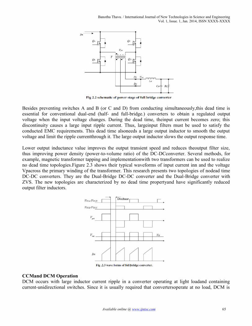
FB-Converter Model in DCM & CCMIn order to reduce the size and the weight of magnetic components it is desirable toincrease theswitching frequency for DC-DC converters. When conventional PWMconverters are operated at highfrequencies, the circuit parasitic has negative effects on theconverter performance. Switching lossesincrease in high power applications and snubbersand/or other means of protection are required, whichintroduce significant losses and lowerthe efficiency. In the case of the conventional full bridgeconverter, the diagonally oppositeswitches (Q1 and Q2, or Q3 and Q4) are turned on and offsimultaneously.Operation:In the FB-PWM converter, when all four switches are turned off, the load current freewheels through therectifier diodes. In this case the energy stored in the leakageinductance of the power transformer causessevere ringing with MOSFET junctioncapacitances. This creates the need for using snubbers thatincrease the overall lossesbringing down the efficiency. If snubbers are not used, the selection of thedevices becomesmore difficult as the voltage rating for these switches has to be much higher. As thevoltagerating goes up, so do the conduction losses and as a result the overall losses increase. At thesametime the cost increases as well. In order to minimize the parasitic ringing, the gatesignals of Q2 and Q4are delayed (phase-shifted) with respect to those of Q1 and Q3, so thatthe primary of the transformer iseither connected to the input voltage or shorted.The leakage inductance current is never interrupted, thussolving the problem of parasitic ringing associated with the conventional full-bridge PWM converter.
Banothu Thavu. / International Journal of New Technologies in Science and EngineeringVol. 1, Issue. 1, Jan. 2014, ISSN XXXX-XXXX
Available online @ www.ijntse.com 65
Besides preventing switches A and B (or C and D) from conducting simultaneously,this dead time isessential for conventional dual-end (half- and full-bridge.) converters to obtain a regulated outputvoltage when the input voltage changes. During the dead time, theinput current becomes zero; thisdiscontinuity causes a large input ripple current. Thus, largeinput filters must be used to satisfy theconducted EMC requirements. This dead time alsoneeds a large output inductor to smooth the outputvoltage and limit the ripple currentthrough it. The large output inductor slows the output response time.
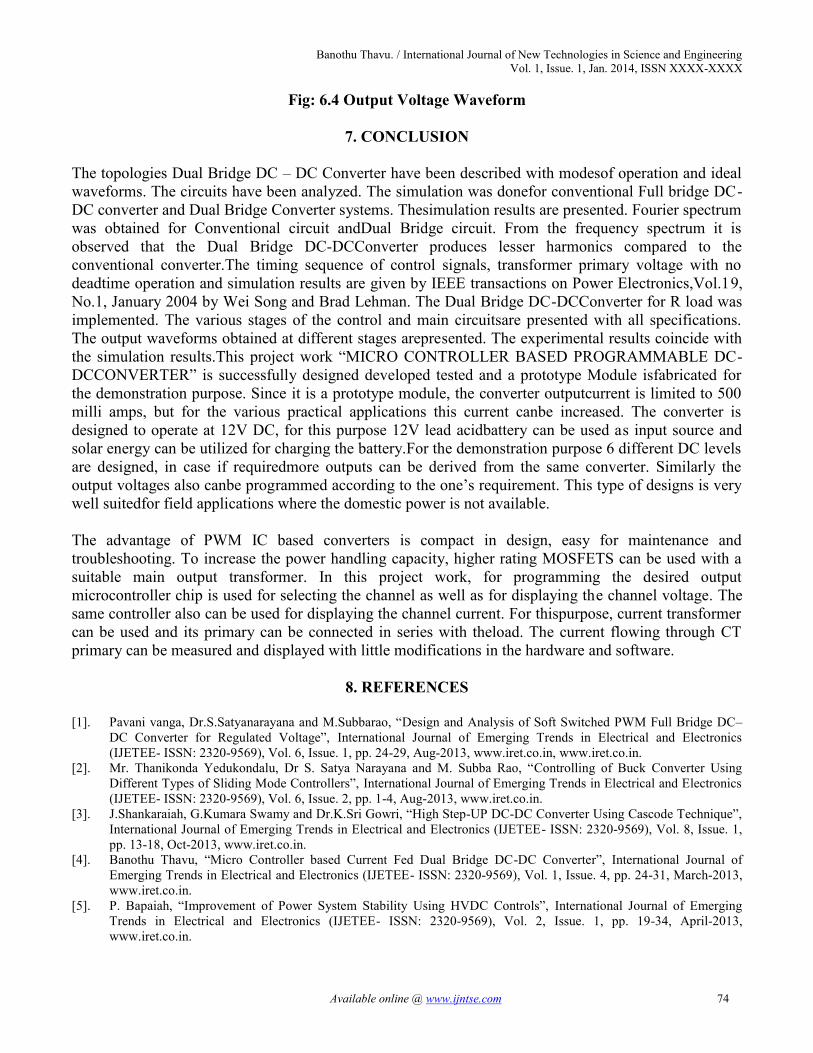
Lower output inductance value improves the output transient speed and reduces theoutput filter size,thus improving power density (power-to-volume ratio) of the DC-DCconverter. Several methods, forexample, magnetic transformer tapping and implementationwith two transformers can be used to realizeno dead time topologies.Figure 2.3 shows their typical waveforms of input current inn and the voltageVpacross the primary winding of the transformer. This research presents two topologies of nodead timeDC-DC converters. They are the Dual-Bridge DC-DC converter and the Dual-Bridge converter withZVS. The new topologies are characterized by no dead time propertyand have significantly reducedoutput filter inductors.
CCMand DCM OperationDCM occurs with large inductor current ripple in a converter operating at light loadand containingcurrent-unidirectional switches. Since it is usually required that convertersoperate at no load, DCM is
Banothu Thavu. / International Journal of New Technologies in Science and EngineeringVol. 1, Issue. 1, Jan. 2014, ISSN XXXX-XXXX
Available online @ www.ijntse.com 66
frequently encountered. The properties of the converter changeradically in the discontinuous conductionmode. The conversion ratio M becomes loaddependent and the output impedance is increased.
The ripple magnitude depends on the applied voltage, the inductance value, and onthe transistorconduction time DTs. However, the ripple does not depend on the loadresistance R. The inductor currentripple magnitude varies with the applied voltages ratherthan the applied currents. If the load resistance isincreased so that the DC load current isdecreased, the ripple magnitude L i. will remain unchanged. Ifthe load resistance increasesthere will be a point when L i I. = is reached. As the load is decreased, thediode currentcannot be negative therefore the diode must become reverse biased before the end oftheswitching period. This is what is known as discontinuous conduction mode (DCM).
3. DUAL BRIDGE DC-DC CONVERTER AND BLOCKDIAGRAM AND ITS BRIEFDESCRIPTION
Dual Bridge DC-DC Converter
With the wide spread use of low voltage microprocessors as well as various low –voltage ICs, researchon DC – DC converters with low voltage and high current output hasbecome increasingly important.There has been a recent trend in industry to use the bridgetopologies in lower conversion power rangesof 100W to 300W and lower input voltage inthe tens of volts. This chapter deals with the circuitdescription and operation of the twoTopologies of Dual bridge DC to DC converter. Also, thecomparison of the circuit withConventional full bridge is done and the Fourier spectra of both thecircuits are presented.
Topologies to Prevent Dead TimeThe topologies used to prevent dead time are the two transformer implementationwith two diode outputrectifier and the tapped primary full bridge circuit.
Banothu Thavu. / International Journal of New Technologies in Science and EngineeringVol. 1, Issue. 1, Jan. 2014, ISSN XXXX-XXXX
Available online @ www.ijntse.com 67
Advantages of No Dead Time OperationThe topologies with no dead time during the operation result in energy beingcontinuously transmittedfrom DC source to the output load in the whole switching period.Because of the lower input ripplecurrent in a no dead time DC – DC converter, theconducted EMI filter is relatively smaller. Loweroutput inductance value improves theoutput transient speed and reduces the output filter size, thusimproving power density (powerto volume ratio) of the DC – DC converterCircuit Description:The switches S1, S2, S3 and S4 form a Full bridge converter. The switches S1, S2 andcapacitors C1, C2form a Half bridge converter. Dual - bridge shown in Figure 3.3 is the.Combination of the two bridges.The two bridges are connected by S5 for bidirectional controlof current. Suppose the converter works insteady state and its output inductor current isunder continuous conduction mode. The high frequencytransformer is modelled by the following: the transformer has theturn’s ratio n, its total stray inductanceLσ is the sum of the primary stray inductance and thesecondary stray inductance reflected across thetransformer to the primary. The magnetizinginductance Lm is much bigger than the leakageinductance.Figure 3.3 Dual bridge DC-DC converters.
Circuit:
Banothu Thavu. / International Journal of New Technologies in Science and EngineeringVol. 1, Issue. 1, Jan. 2014, ISSN XXXX-XXXX
Available online @ www.ijntse.com 68
Circuit OperationIn mode 1 as in Figure 3.4(a) the switches S1 and S4 are turned on. TheLoad Current flows through S1,load and S4. The voltage across the primary side oftransformer, Vp = Vin and voltage across thesecondary side of transformer, Vs=nVin. Inputcurrent iin increases and equals the primary windingcurrent ip.
In mode 2 as in Figure 3.4. (b) The switches S4 is off and S5 is on. The current ip flowsthrough S1, loadand S5 charging C2 while the capacitor C1 discharges. The voltages, Vp =Vin/2 and Vs = nVp =nVin/2. At t2, S1 and S5 turn off and S2 and S3 turn on.
Banothu Thavu. / International Journal of New Technologies in Science and EngineeringVol. 1, Issue. 1, Jan. 2014, ISSN XXXX-XXXX
Available online @ www.ijntse.com 69
The mode 3 operation as in Figure 3.4(c) is in symmetry with time intervalt0 < t< t1 and the voltage,Vs= nVp=-nVin. The operation of mode 4 as in Figure 3.4(d) is insymmetry with time interval t1< t< t2and now the voltage, Vs= nVp =-nVin/2.
Idealized WaveformsThe ideal waveforms of the Dual Bridge converter are shown inFigure 3.5
The control signals of the switches S1 to S5 are as shown. VS1 and VS2 are two 50%duty ratiocomplementary control signals of S1 and S2. VS3 and VS4 are control signals ofswitches S3 and S4with duty ratio, D and switching frequency, f. VS5 operates at f0 = 2f (T0 =T/2). The values of D and(1-D) are obtained from the equations 4.1 and 4.2.D = (t1 - t0) / T0 = (t3 – t2) / T0 … (3.1)1 - D = (t2 - t1)/ T0 = (t4 – t3) / T0 … (3.2)
Banothu Thavu. / International Journal of New Technologies in Science and EngineeringVol. 1, Issue. 1, Jan. 2014, ISSN XXXX-XXXX
Available online @ www.ijntse.com 70
Advantages of Dual bridge topology over ConventionalMethodsThe following are the advantages of Dual bridge topology over the conventional methods._ No dead time._ One power transformer and no magnetic tapping on the primary winding._ significantly reduced input current ripple._ significantly reduced output filter inductance value, thus inductor size._ Less stress on switching components._ Self – Driven synchronous rectifiers can be used as output rectifiers to increase thePower efficiency of the converter._ The ZVS dual bridge DC – DC converter is implemented by fixed frequency PWMControl without using phase – modulated control.
4. BLOCK DIAGRAM AND ITS BRIEF DESCRIPTIONThe block diagram and its brief description of the project work “MICROCONTROLLER BASEDPROGRAMMABLE DC - DC CONVERTER” is explained in thischapter. The main block diagram,which is shown at the end of this chapter, consistsfollowing blocks.
Fig: 4.1 block diagram for micro controller based programmable dc - dc converter
DC- DC Converters – An OverviewMany Industrial drives and processes take power from DC voltage sources. In mostcases, conversion ofDC source voltage to different levels is required. For example, Bus,Train, Ship, Flight, etc; Generallythese kind of huge traveling bodies are equipped with hugebatteries, and with the help of this DC – DCConverter, different DC levels are generated toenergize various electronics equipment’s. There
Banothu Thavu. / International Journal of New Technologies in Science and EngineeringVol. 1, Issue. 1, Jan. 2014, ISSN XXXX-XXXX
Available online @ www.ijntse.com 71
Fig: 4.2 Hardware implementation of“Micro controller based current fed dual bridge dc-dc converter”
is a need to energize electrical devices likeTube light, cooler, etc.; for which AC voltage is required andwith the help of an inverterconnected to a fixed DC source as input source, the required AC voltage canbe generated.Weather it is a Inverter or Converter, the input source is DC, and generates differentDClevels or from DC to AC source to energize various Electrical and Electronic devices belongsto thesetraveling bodies.
Many Industries (manufacturers of DC – DC converters) offering high powerconverters up to 1000W.Using high switching frequency, hybrid circuit, chip-on-board andsurface mounting technologies, theseDC-DC converters provide high power density, a lowprofile and high efficiency. Accurate currentsharing and fixed frequency synchronization ofDC-DC converters allows reliable parallel operation foreasy expansion. The product linecovers commercial, industrial and military grade applications.
SIMULATION RESULTS5. Simulation of Current Fed Full bridge DC-DC converter
Simulation circuit for current fed ful bridge DC-DC converter is shown in fig: 5.1
Banothu Thavu. / International Journal of New Technologies in Science and EngineeringVol. 1, Issue. 1, Jan. 2014, ISSN XXXX-XXXX
Available online @ www.ijntse.com 72
Fig: 5.1 Current-Fed Full Bridge DC-DC Converter
Fig: 5.2 input and Output Voltage Waveforms
Fig: 5.3 Transformer & Secondary Waveforms
Fig: 5.4Output Voltage WaveformThe simulation was done for conventional half bridge and Full bridge DC-DCconverter and Dual BridgeConverter systems. The simulation results are presented. Fourierspectrum was obtained for Conventionalcircuit and Dual Bridge circuit. From the frequencyspectrum it is observed that the Dual bridge DC-DCconverter produces lesser harmonicscompared to the conventional converter. Significantly reduced inputcurrent ripple.
6. Simulation of Current Fed Dual bridge DC-DC converter
Banothu Thavu. / International Journal of New Technologies in Science and EngineeringVol. 1, Issue. 1, Jan. 2014, ISSN XXXX-XXXX
Banothu Thavu. / International Journal of New Technologies in Science and EngineeringVol. 1, Issue. 1, Jan. 2014, ISSN XXXX-XXXX
Available online @ www.ijntse.com 74
Fig: 6.4 Output Voltage Waveform
7. CONCLUSION
The topologies Dual Bridge DC – DC Converter have been described with modesof operation and idealwaveforms. The circuits have been analyzed. The simulation was donefor conventional Full bridge DC-DC converter and Dual Bridge Converter systems. Thesimulation results are presented. Fourier spectrumwas obtained for Conventional circuit andDual Bridge circuit. From the frequency spectrum it isobserved that the Dual Bridge DC-DCConverter produces lesser harmonics compared to theconventional converter.The timing sequence of control signals, transformer primary voltage with nodeadtime operation and simulation results are given by IEEE transactions on Power Electronics,Vol.19,No.1, January 2004 by Wei Song and Brad Lehman. The Dual Bridge DC-DCConverter for R load wasimplemented. The various stages of the control and main circuitsare presented with all specifications.The output waveforms obtained at different stages arepresented. The experimental results coincide withthe simulation results.This project work “MICRO CONTROLLER BASED PROGRAMMABLE DC-DCCONVERTER” is successfully designed developed tested and a prototype Module isfabricated forthe demonstration purpose. Since it is a prototype module, the converter outputcurrent is limited to 500milli amps, but for the various practical applications this current canbe increased. The converter isdesigned to operate at 12V DC, for this purpose 12V lead acidbattery can be used as input source andsolar energy can be utilized for charging the battery.For the demonstration purpose 6 different DC levelsare designed, in case if requiredmore outputs can be derived from the same converter. Similarly theoutput voltages also canbe programmed according to the one’s requirement. This type of designs is verywell suitedfor field applications where the domestic power is not available.
The advantage of PWM IC based converters is compact in design, easy for maintenance andtroubleshooting. To increase the power handling capacity, higher rating MOSFETS can be used with asuitable main output transformer. In this project work, for programming the desired outputmicrocontroller chip is used for selecting the channel as well as for displaying the channel voltage. Thesame controller also can be used for displaying the channel current. For thispurpose, current transformercan be used and its primary can be connected in series with theload. The current flowing through CTprimary can be measured and displayed with little modifications in the hardware and software.
8. REFERENCES
[1]. Pavani vanga, Dr.S.Satyanarayana and M.Subbarao, “Design and Analysis of Soft Switched PWM Full Bridge DC–DC Converter for Regulated Voltage”, International Journal of Emerging Trends in Electrical and Electronics(IJETEE- ISSN: 2320-9569), Vol. 6, Issue. 1, pp. 24-29, Aug-2013, www.iret.co.in, www.iret.co.in.
[2]. Mr. Thanikonda Yedukondalu, Dr S. Satya Narayana and M. Subba Rao, “Controlling of Buck Converter UsingDifferent Types of Sliding Mode Controllers”, International Journal of Emerging Trends in Electrical and Electronics(IJETEE- ISSN: 2320-9569), Vol. 6, Issue. 2, pp. 1-4, Aug-2013, www.iret.co.in.
[3]. J.Shankaraiah, G.Kumara Swamy and Dr.K.Sri Gowri, “High Step-UP DC-DC Converter Using Cascode Technique”,International Journal of Emerging Trends in Electrical and Electronics (IJETEE- ISSN: 2320-9569), Vol. 8, Issue. 1,pp. 13-18, Oct-2013, www.iret.co.in.
[4]. Banothu Thavu, “Micro Controller based Current Fed Dual Bridge DC-DC Converter”, International Journal ofEmerging Trends in Electrical and Electronics (IJETEE- ISSN: 2320-9569), Vol. 1, Issue. 4, pp. 24-31, March-2013,www.iret.co.in.
[5]. P. Bapaiah, “Improvement of Power System Stability Using HVDC Controls”, International Journal of EmergingTrends in Electrical and Electronics (IJETEE- ISSN: 2320-9569), Vol. 2, Issue. 1, pp. 19-34, April-2013,www.iret.co.in.
Banothu Thavu. / International Journal of New Technologies in Science and EngineeringVol. 1, Issue. 1, Jan. 2014, ISSN XXXX-XXXX
Available online @ www.ijntse.com 75
[6]. Brijesh M.Patel, Minesh k. Joshi and Dhaval N. Tailor, “Design and Simulation of Boost Converter for ConstantOutput Voltage”, International Journal of Emerging Trends in Electrical and Electronics (IJETEE- ISSN: 2320-9569),Vol. 8, Issue. 1, pp. 19-24, Oct-2013, www.iret.co.in.
[7]. U.Vinod kumar and P.Sai Sampath Kumar, “Loaded Resonant Converter for the DC to DC Energy ConversionApplications”, International Journal of Emerging Trends in Electrical and Electronics (IJETEE- ISSN: 2320-9569),Vol. 6, Issue. 2, pp. 21-28, Aug-2013, www.iret.co.in.
[8]. Jil sutaria, Manisha shah and Chirag chauhan, “Comparative Analysis of Single Phase and Multiphase Bi-DirectionalDC-DC Converter”, International Journal of Emerging Trends in Electrical and Electronics (IJETEE- ISSN: 2320-9569), Vol. 2, Issue. 1, pp. 41-46, April-2013, www.iret.co.in.
[9]. Dhana Prasad Duggapu, Satya Venkata Kishore Pulavarthi and Swathi Nulakajodu, “Comparison between DiodeClamped and HBridge Multilevel Inverter (5 to 15 odd levels)”, International Journal of Emerging Trends in Electricaland Electronics (IJETEE- ISSN: 2320-9569), Vol. 1, Issue. 4, pp. 66-78, March-2013, www.iret.co.in.
[10]. P.Chaithanya Deepak and S. Nagaraja Rao, “Cascaded H-Bridge Multilevel Inverter Using Inverted Sine Wave PWMTechnique”, International Journal of Emerging Trends in Electrical and Electronics (IJETEE- ISSN: 2320-9569), Vol.6, Issue. 1, pp. 39-44, Aug-2013, www.iret.co.in.
[11]. Dharmesh.V.Khakhkhar, “Design and Simulation of Novel Integral Switching Cycle Control for Heating Load”,International Journal of Emerging Trends in Electrical and Electronics (IJETEE- ISSN: 2320-9569), Vol. 5, Issue. 1,pp. 41-44, July-2013, www.iret.co.in.
[12]. Mukesh Gupta, Sachin Kumar and Vagicharla Karthik, “Design and Implementation of Cosine Control Firing Schemefor Single Phase Fully Controlled Bridge Rectifier”, International Journal of Emerging Trends in Electrical andElectronics (IJETEE- ISSN: 2320-9569), Vol. 3, Issue. 1, pp. 40-46, May-2013, www.iret.co.in.
[13]. L. Sai Suman Rao and S. Nagaraja Rao, “Three Level Neutral Point Clamped Back to Back Converter”, InternationalJournal of Emerging Trends in Electrical and Electronics (IJETEE- ISSN: 2320-9569), Vol. 6, Issue. 1, pp. 45-50,Aug-2013, www.iret.co.in.
[14]. M. M. Irfan, “Simulation of High Voltage Gain Zero Voltage Switching Boost Converter”, International Journal ofEngineering Trends in Electrical and Electronics (IJETEE- ISSN: 2320-9569) Vol. 3, Issue 1, pp. 88-92, May, 2013,www.iret.co.in.
[15]. A Mallikarjuna Prasad, S Thirumalaiah, U chaithanya and P Nagarjuna, “Simulation of New Multilevel InverterTopology”, International Journal of Emerging Trends in Electrical and Electronics (IJETEE- ISSN: 2320-9569), Vol.1, Issue. 1, pp. 68-73, March-2013, www.iret.co.in.
[16]. Mr. Ambadas. S. Mane and Mr. Vijay. B. Suryawanshi, “Analysis of Five Level Inverter”, International Journal ofEmerging Trends in Electrical and Electronics (IJETEE- ISSN: 2320-9569), Vol. 1, Issue. 1, pp. 98-101, March-2013,www.iret.co.in.
[17]. Mashhood Hasan, Dinesh Kumar and Zafar Khan, “Multimodules of Diode Clamped Multilevel Converter: A NovelOption for High Power Facts Controller”, International Journal of Emerging Trends in Electrical and Electronics(IJETEE- ISSN: 2320-9569), Vol. 2, Issue. 1, pp. 109-112, April-2013, www.iret.co.in.
[18]. Santhosh Kumar Vasireddy and Munfar Ali G, “Parallel Power Flow AC/DC Converter with Input Power FactorCorrection and Tight Output Voltage Regulation for Universal Voltage Applications”, International Journal ofEmerging Trends in Electrical and Electronics (IJETEE- ISSN: 2320-9569), Vol. 1, Issue. 4, pp. 55-65, March-2013,www.iret.co.in.
[19]. R. Subbarayudu, K. Kishore Reddy and Dr K. Sri Gowri, “A Novel Power Converter for Integrated Traction EnergyStorage”, International Journal of Emerging Trends in Electrical and Electronics (IJETEE- ISSN: 2320-9569), Vol. 6,Issue. 2, pp. 37-45, Aug-2013, www.iret.co.in.
[20]. Manish Raval and Ved Vyas Dwivedi, “Commencing the FACTS in Variable Energy Sources Network to OptimizeExisting Transmission System with Stability”, International Journal of Emerging Trends in Electrical and Electronics(IJETEE- ISSN: 2320-9569), Vol. 2, Issue. 1, pp. 96-104, April-2013, www.iret.co.in.
[21]. Ankush Malhar and Parag Nijhawan, “Improvement of Power Quality of Distribution Network with DTC Drive UsingUPQC”, International Journal of Emerging Trends in Electrical and Electronics (IJETEE- ISSN: 2320-9569), Vol. 5,Issue. 2, pp. 1-6, July-2013, www.iret.co.in.
[22]. Akhib Khan Bahamani, Dr. G.V. Siva Krishna Rao, Dr. A.A. Powly Thomas and Dr V.C. Veera Reddy, “Modelingand Digital Simulation of DPFC System using Matlab Simulink”, International Journal of Emerging Trends inElectrical and Electronics (IJETEE- ISSN: 2320-9569), Vol. 6, Issue. 1, pp. 1-5, Aug-2013, www.iret.co.in.
[23]. P. Bapaiah, “Power Quality Improvement by using DSTATCOM”, International Journal of Emerging Trends inElectrical and Electronics (IJETEE- ISSN: 2320-9569), Vol. 2, Issue. 4, pp. 1-12, April-2013, www.iret.co.in
Banothu Thavu. / International Journal of New Technologies in Science and EngineeringVol. 1, Issue. 1, Jan. 2014, ISSN XXXX-XXXX
Available online @ www.ijntse.com 76
[24]. Sudharshan Rao Gandimeni and Vijay Kumar K, “Unified Power Quality Conditioner (UPQC) During Voltage Sagand Swell”, International Journal of Emerging Trends in Electrical and Electronics (IJETEE- ISSN: 2320-9569), Vol.1, Issue. 4, pp. 12-23, March-2013, www.iret.co.in
[25]. Rajshekar Sinagham and K. Vijay Kumar, “Role of Interline Power Flow Controller for Voltage Quality”,International Journal of Emerging Trends in Electrical and Electronics (IJETEE- ISSN: 2320-9569), Vol. 1, Issue. 4,pp. 51-54, March-2013, www.iret.co.in
[26]. Seelam Swarupa, and K. V. S. Ramachandra Murthy, “Control Strategy for Unified Power Flow Controller”,International Journal of Emerging Trends in Electrical and Electronics (IJETEE- ISSN: 2320-9569), Vol. 2, Issue. 1,pp. 59-63, April-2013, www.iret.co.in.
[27]. Rajan Sharma and Parag Nijhawan, “Role of DSTATCOM to Improve Power Quality of Distribution Network withFOC Induction Motor Drive as Load”, International Journal of Emerging Trends in Electrical and Electronics(IJETEE- ISSN: 2320-9569), Vol. 5, Issue. 1, pp. 83-88, July-2013, www.iret.co.in.
[28]. Mr. N. Peddaiah, Mr. K. Veera Sekhar, Mr. J. Lakshman and Mr. G. Rajashekhar, “A Revolutionary Idea to ImprovePower Quality by Using Distributed Power Flow Controller [DPFC]”, International Journal of Emerging Trends inElectrical and Electronics (IJETEE- ISSN: 2320-9569), Vol. 2, Issue. 1, pp. 1-5, April-2013, www.iret.co.in.
[29]. R.Dinesh kumar and P.Karuppusamy, “Performance Analysis of Soft Switched Seven Level Inverter for PhotovoltaicSystem”, International Journal of Emerging Trends in Electrical and Electronics (IJETEE – ISSN: 2320-9569) Vol. 5,Issue. 3, pp. 11-16, July-2013, www.iret.co.in.
[30]. M.Balachandran and N.P.Subramaniam, “Fuzzy Logic Controller for Z-Source Cascaded Multilevel Inverter”,International Journal of Emerging Trends in Electrical and Electronics (IJETEE- ISSN: 2320-9569), Vol. 6, Issue. 1,pp .30-34, Aug-2013, www.iret.co.in.
[31]. Dr Rama Rao P.V.V. and Ms. N. VENUPRIYA, “SPWM Based Two Level VSI for Microgrid Applications”,International Journal of Emerging Trends in Electrical and Electronics (IJETEE- ISSN: 2320-9569), Vol. 7, Issue. 1,pp. 3-6, Sep-2013, www.iret.co.in.
[32]. Omveer Singh, Prabhakar Tiwari, Ibraheem and Arunesh Kr. Singh, “A Survey of Recent Automatic GenerationControl Strategies in Power Systems”, International Journal of Emerging Trends in Electrical and Electronics(IJETEE- ISSN: 2320-9569), Vol. 7, Issue. 2, pp. 1-14, Sep-2013, www.iret.co.in.
[33]. Dr. Tarun Chopra, “Future Directions of Research in Fault Diagnosis and Intelligent Control of Complex Systems”,International Journal of Emerging Trends in Electrical and Electronics (IJETEE – ISSN: 2320-9569) Vol. 7, Issue. 1,pp. 1-2, Sep-2013, www.iret.co.in.
[34]. P.Pugazhendiran, M.Sujith and Dr.S.S.Jayachandran, “Matlab Based HVCT Fault Analysis”, International Journal ofEmerging Trends in Electrical and Electronics (IJETEE- ISSN: 2320-9569), Vol. 2, Issue. 1, pp. 105-108, April-2013,www.iret.co.in.
[35]. Jayeshkumar G. Priolkar and Vinayak N. Shet, “A Review on Protection Issues in Microgrid”, International Journal ofEmerging Trends in Electrical and Electronics (IJETEE- ISSN: 2320-9569), Vol. 2, Issue. 1, pp. 6-11, April-2013,www.iret.co.in.
[36]. Neha Gupta, Harish Balaga, D. N. Vishwakarma, “Numerical Differential Protection of Power Transformer using GATrained ANN”, International Journal of Emerging Trends in Electrical and Electronics (IJETEE- ISSN: 2320-9569),Vol. 3, Issue.1, pp. 1-7, May-2013, www.iret.co.in.
[37]. T. Hariharan, S. Raja and S. Hareesh, “Real Power Loss Minimization using Fuzzy logic Controller”, InternationalJournal of Emerging Trends in Electrical and Electronics (IJETEE- ISSN: 2320-9569), Vol. 6, Issue. 2, pp. 46-49,Aug-2013, www.iret.co.in
[38]. T.Hariharan and Dr.M.GopalaKrishnan, “Optimal Reactive Power Flow using Fuzzy logic Controller Technique”,International Journal of Emerging Trends in Electrical and Electronics (IJETEE- ISSN: 2320-9569), Vol. 1, Issue. 1,pp. 49-53, March-2013, www.iret.co.in
[39]. Miss Shraddha Mehta, Miss Mital Upahaya, Miss Mita Rathod, “CloudComputing: A Review”, International Journalof Emerging Trends in Electrical and Electronics (IJETEE- ISSN: 2320-9569), Vol. 4, Issue. 2, pp. 29-31, June-2013,www.iret.co.in.
[40]. Ms. Mohini Pande, Mr.Dishant Vyas, Ms.Roopakiran Yeluri and Prof.(Mrs).Suvarna K.Gaikwad, “MicrocontrollerBased Neural Network Controlled Low Cost Autonomous Vehicle”, International Journal of Emerging Trends inElectrical and Electronics (IJETEE- ISSN: 2320-9569), Vol. 2, Issue. 4, pp. 36-39, April-2013, www.iret.co.in.
[41]. Arun Kumar, Munish Vashishth and Lalit Rai. “Liquid level control of coupled tank system using Fractional PIDcontroller”, International Journal of Emerging Trends in Electrical and Electronics (IJETEE- ISSN: 2320-9569), Vol.3, Issue. 1, May-2013, www.iret.co.in.
Banothu Thavu. / International Journal of New Technologies in Science and EngineeringVol. 1, Issue. 1, Jan. 2014, ISSN XXXX-XXXX
Available online @ www.ijntse.com 77
[42]. Rajdeep Singh, Kumari Kalpna, Dawindar Kumar Mishra, “Hybrid Optimization Technique for Circuit PartitioningUsing PSO and Genetic Algorithm”, International Journal of Emerging Trends in Electrical and Electronics (IJETEE-ISSN: 2320-9569), Vol. 4, Issue. 2, pp. 69-71, June-2013, www.iret.co.in.
[43]. Manju khare, Yogendra kumar, Ganga Agnihotri and V.K. Sethi, “Simulation and Analysis of Maximum-Power-Point-Tracker for Photovoltaic Arrays”, International Journal of Emerging Trends in Electrical and Electronics(IJETEE- ISSN: 2320-9569), Vol. 1, Issue. 1, pp .1-6, March-2013, www.iret.co.in.
[44]. MoganapriyaKrishnakumar andPanneerselvamManickam, “Modeling and Neuro-Fuzzy Control of DFIG in WindPower Systems for Grid Power Leveling”, International Journal of Emerging Trends in Electrical and Electronics(IJETEE – ISSN: 2320-9569) Vol. 3, Issue.1, pp. 8-14, May-2013, www.iret.co.in.
[45]. Devendra Singh, Gyanendra yadav, DivyaPratap Singh and GyanRanjan Gupta, “Maximum Power Point Tracking ForPV Based Solar System: A Review”, International Journal of Emerging Trends in Electrical and Electronics (IJETEE-ISSN: 2320-9569), Vol. 3, Issue.1, pp. 29-30, May-2013, www.iret.co.in.
[46]. Bhanupriya.R and Subasri.R, “Nonlinear Disturbance Control in a Wind Energy Conversion System Using Theta-DControl”, International Journal of Emerging Trends in Electrical and Electronics (IJETEE- ISSN: 2320-9569), Vol. 6,Issue. 1, pp. 35-38, Aug-2013, www.iret.co.in.
[47]. Rupert Gouws and Elizbe van Niekerk, “Prototype Super-capacitor Photovoltaic Streetlight with xLogic SuperRelayFunctionality”, International Journal of Emerging Trends in Electrical and Electronics (IJETEE- ISSN: 2320-9569),Vol. 7, Issue. 1, pp. 34-39, Sep-2013, www.iret.co.in.
[48]. Brijesh M. Patel, Kalpesh J.Chudasma, Hardik A.Shah, “Simulation of Single Phase Inverter using PSIM Software forSolar P.V. System give Constant Output Voltage at Different Solar Radiation”, International Journal of EmergingTrends in Electrical and Electronics (IJETEE- ISSN: 2320-9569), Vol. 4, Issue. 1, pp. 26-31, June-2013,www.iret.co.in
[49]. Mrs. S. Sathana and Ms. Bindukala M.P, “Hybrid Solar and Wind Power Conversion Using DFIG with Grid PowerLeveling”, International Journal of Emerging Trends in Electrical and Electronics (IJETEE- ISSN: 2320-9569), Vol. 1,Issue. 1, pp. 43-48, March-2013, www.iret.co.in.
[50]. Mr.K.Saravanan and Dr. H. Habeebullah Sait, “Multi Input Converter for Distributed Renewable Energy Sources”,International Journal of Emerging Trends in Electrical and Electronics (IJETEE- ISSN: 2320-9569), Vol. 2, Issue. 1,pp. 51-58, April-2013, www.iret.co.in.
[51]. Mrs. Thivya Balasubramanian., Mr. Rajesh. T. Mr.RajaPerumal T.A, “Load Sharing In A Hybrid Power System WithRenewable Energy Sources”, International Journal of Engineering Trends in Electrical and Electronics (IJETEE-ISSN: 2320-9569) Vol. 3, Issue 1, pp. 35-39, May, 2013, www.iret.co.in.
[52]. K. K. Saravanan , Dr. N. Stalin and S. T. Jayasuthahar, “Review of Renewable Energy Resources in Clean GreenEnvironment”, International Journal of Emerging Trends in Electrical and Electronics (IJETEE- ISSN: 2320-9569),Vol. 1, Issue. 1, pp. 54-58, March-2013, www.iret.co.in.
[53]. S.Sathish Kumar and S. Chinnaiya, “Switched Inductor Quasi-z-source Inverter for PMSG based Wind EnergyConversion System”, International Journal of Emerging Trends in Electrical and Electronics (IJETEE- ISSN: 2320-9569), Vol. 3, Issue. 1, pp. 41-46, May-2013, www.iret.co.in.
[54]. C.Bhuvaneswari and R.Rajeswari, “Study Analysis of Hybrid Power Plant (Wind-Solar) - Vertical Axis WindTurbine-Giromill Darrieus Type with Evacuated Tube Collectors”, International Journal of Emerging Trends inElectrical and Electronics (IJETEE- ISSN: 2320-9569), Vol. 1, Issue. 1, pp. 80-83, March-2013, www.iret.co.in.
[55]. Deepali Sharma, Uphar Tandon, Nitin Saxena, “Development of 1000W, 230volt Solar Photovoltaic Power ElectronicConversion System”, International Journal of Emerging Trends in Electrical and Electronics (IJETEE- ISSN: 2320-9569), Vol. 3, Issue. 1, pp. 70-74, May-2013, www.iret.co.in.
[56]. K.Gayathri, S.gomathi and T.Suganya, “Design of Intelligent Solar Power System Using PSO Based MPPT withAutomatic Switching between ON grid and OFF Grid Connections”, International Journal of Emerging Trends inElectrical and Electronics (IJETEE- ISSN: 2320-9569), Vol. 1, Issue. 1, pp. 95-97, March-2013, www.iret.co.in.
[57]. D.Pugazhenthi, P.Sathishbabu and R.M.SasiRaja, “A NOVEL NINE-SWITCH CONVERTER FOR SOLARENERGY GENERATION SYSTEMS”, International Journal of Engineering Trends in Electrical andElectronics(IJETEE- ISSN: 2320-9569) Vol. 3, Issue 1, pp. 83-87, May, 2013, www.iret.co.in.
[58]. Panchal Mehulkumar J and Ved Vyas Dwivedi, “Sustainable Energy Development and Appropriate Options to EnergySustainability Threats in India”, International Journal of Emerging Trends in Electrical and Electronics (IJETEE-ISSN: 2320-9569), Vol. 2, Issue. 4, pp. 83-89, April-2013, www.iret.co.in.
[59]. Mr. Karthick R.T and Dr. Ashok Kumar L, “Stand-Alone Solar Power Generation System with Constant CurrentDischarge”, International Journal of Emerging Trends in Electrical and Electronics (IJETEE- ISSN: 2320-9569), Vol.5, Issue. 1, pp. 108-114
Banothu Thavu. / International Journal of New Technologies in Science and EngineeringVol. 1, Issue. 1, Jan. 2014, ISSN XXXX-XXXX
Available online @ www.ijntse.com 78
[60]. Banothu Thavu, Thuraka Rajendra, Ravi Bukya and M. Maheswararao, “Modeling and Power-SynchronizationControl of Grid-Connected VSC- HVDC”, International Journal of Emerging Trends in Electrical and Electronics(IJETEE- ISSN: 2320-9569), Vol. 1, Issue. 1, pp .84-94, March-2013, www.iret.co.in.
[61]. R.Satish Kumar , D. Lenine and Ch. Sai Babu, “Modeling and Analysis of PFC with Appreciable Voltage Ripple toAchieve Fast Transient Response”, International Journal of Emerging Trends in Electrical and Electronics (IJETEE-ISSN: 2320-9569), Vol. 7, Issue. 1, pp. 53-57, Sep-2013, www.iret.co.in.
[62]. M.Lavanya and J.Krithika Jothi, “Reliability Assessment of Power Generation System Using Seeker OptimizationAlgorithm”, International Journal of Emerging Trends in Electrical and Electronics (IJETEE- ISSN: 2320-9569), Vol.1, Issue. 1, pp. 59-63, March-2013, www.iret.co.in.
[63]. Apoorva Saxena and Subhash Chandra, “Rural Off Grid Electrification Using Hybrid Mini grid and its SocioEconomic Impact : A Case Study of District Pilibhit”, International Journal of Emerging Trends in Electrical andElectronics (IJETEE- ISSN: 2320-9569), Vol. 2, Issue. 1, pp. 70-73, April-2013, www.iret.co.in.
[64]. C. Brahmananda Babu, D. Lenine and Chintapalli. K. Sudhakar, “An Improved Performance of Power FactorCorrection Circuits with Average Current Control Approach”, International Journal of Emerging Trends in Electricaland Electronics (IJETEE- ISSN: 2320-9569), Vol. 7, Issue. 1, pp.58-62, Sep-2013, www.iret.co.in.
[65]. K ElanSeralathan, Joseph Richards A, Rajasekaran C, Sambath kumar S and Santhosh Kumar G, “Modleing ofElectric Tree Progression in the Presence of Barrier”, International Journal of Emerging Trends in Electrical andElectronics (IJETEE- ISSN: 2320-9569), Vol. 5, Issue. 2, pp. 49-52, July-2013, www.iret.co.in
[66]. Ratandeep Gupta, Rashmi Chandra, Vikas Chaudhary and Nitin Saxena, “OPTIMAL LOAD DISPATCH USINGBCOEEFICIENT”, International Journal of Emerging Trends in Electrical and Electronics (IJETEE- ISSN: 2320-9569), Vol. 3, Issue. 1, pp. 53-56, May-2013, www.iret.co.in.
[67]. K.Sandhya, Dr.A.Jaya Laxmi and Dr.M.P.Soni, “Optimal Placement of Distribution Generation in Radial DistributionSystem”, International Journal of Emerging Trends in Electrical and Electronics (IJETEE- ISSN: 2320-9569), Vol. 2,Issue. 1, pp. 74-80, April-2013, www.iret.co.in.
[68]. K V S Ramachandra Murthy, Mamta Karayat, P. K. Das, A. Ravi Shankar & G. V. Srihara Rao, “Loss LessDistribution using Optimal Capacitor and Type -3 DG Placement”, International Journal of Engineering Trends inElectrical and Electronics (IJETEE- ISSN: 2320-9569) Vol. 3, Issue 1, pp. 57-60, May, 2013, www.iret.co.in.
[69]. K ElanSeralathan, Joseph Richards A, Rajasekaran C, Sambath kumar S and Santhosh Kumar G, “Modleing ofElectric Tree Progression with Different Barrier Width and Field Studies”, International Journal of Emerging Trendsin Electrical and Electronics (IJETEE- ISSN: 2320-9569), Vol. 5, Issue. 2, pp. 53-58, July-2013, www.iret.co.in.
[70]. K ElanSeralathan, Joseph Richards A, Rajasekaran C, Sambath kumar S and Santhosh Kumar G, “Understanding theField Conditions Around the Barrier for Electric Tree Propagation”, International Journal of Emerging Trends inElectrical and Electronics (IJETEE- ISSN: 2320-9569), Vol. 5, Issue. 2, Jpp. 59-63, uly-2013, www.iret.co.in.
[71]. Ms.Santoshi Gupta, “Simulation of PQ Disturbances by MATLAB”, International Journal of Emerging Trends inElectrical and Electronics (IJETEE- ISSN: 2320-9569), Vol. 1, Issue. 1, pp. 74-79, March-2013, www.iret.co.in.
[72]. M.Sankar, G.Murugaraja, D.VasanthaKumar, S.Vignesh, B.Ramachendran, “Simulate and Analysis of the Limit ofOutput Capacitor Reduction in Power Factor Correctors by Distorting the Line Input Current”, International Journal ofEngineering Trends in Electrical and Electronics (IJETEE- ISSN: 2320-9569) Vol. 3, Issue 1, pp. 65-69, May, 2013,www.iret.co.in.
[73]. Mrs Babita Panda, Dr. Bhagabata Panda and Dr. P.K Hota, “Smart Grid Hybrid Generation System”, InternationalJournal of Emerging Trends in Electrical and Electronics (IJETEE- ISSN: 2320-9569), Vol. 2, Issue. 4, pp. 68-70,April-2013, www.iret.co.in.
[74]. M. Koteswara Rao, T.Ganeshkumar and PappuPawan Puthra, “Mitigation of Voltage Sag and Voltage Swell by UsingD-STATCOM and PWM Switched Autotransformer”, International Journal of Emerging Trends in Electrical andElectronics (IJETEE- ISSN: 2320-9569), Vol. 7, Issue. 1, pp. 40-48, Sep.-2013, www.iret.co.in.
[75]. T. S. Sirish, G. V. Srihara Rao & K V S Ramachandra Murthy, “Optimal Capacitor and DG Placement for Loss LessDistribution on 69- Bus System using KVS – Direct Search Algorithm”, International Journal of Engineering Trendsin Electrical and Electronics(IJETEE- ISSN: 2320-9569), Vol. 3, Issue 1, pp. 31-34, May, 2013, www.iret.co.in
[76]. K. Sreekanth Reddy, “Simulation of ZVS H-Bridge Inverter Using Soft Switching Boost Converter”, InternationalJournal of Emerging Trends in Electrical and Electronics (IJETEE- ISSN: 2320-9569), Vol. 7, Issue. 1, pp. 21-26,Sep-2013, www.iret.co.in
[77]. Shilpi Nayak, Shraddha Kaushik and Ishawari Prasad Sahu, “Algorithm for Removal of DC Offset in Current andVoltage Signals”, International Journal of Emerging Trends in Electrical and Electronics (IJETEE- ISSN: 2320-9569),Vol. 1, Issue. 1, pp. 40-42, March-2013, www.iret.co.in
Banothu Thavu. / International Journal of New Technologies in Science and EngineeringVol. 1, Issue. 1, Jan. 2014, ISSN XXXX-XXXX
Available online @ www.ijntse.com 79
[78]. T. Nireekshana , Dr.G.Kesava Rao and Dr.S.Siva Naga Raju, “Congestion Mitigation based on Generator Sensitivitiesin Deregulation”, International Journal of Emerging Trends in Electrical and Electronics (IJETEE- ISSN: 2320-9569),Vol. 1, Issue. 1, pp. 13-19, March-2013, www.iret.co.in
[79]. M.Abitha Thangam and Dr.V.Gopalakrishnan, “Power Factor Improvement Using PQ Theory Based HybridController for Three Phase Converter”, International Journal of Emerging Trends in Electrical and Electronics(IJETEE- ISSN: 2320-9569), Vol. 1, Issue. 1, pp. 20-24, March-2013, www.iret.co.in
[80]. Mamta Karayat, G. V. Srihara Rao, Ravi Kumar Kenguva & K V S Ramachandra Murthy, “Optimal Capacitor andType -2 DG Placement using Modified KVS – Direct Search Algorithm for Loss Less Distribution”, InternationalJournal of Engineering Trends in Electrical and Electronics(IJETEE- ISSN: 2320-9569) Vol. 3, Issue 1, pp. 20-24,May, 2013, www.iret.co.in
[81]. U. Ravi Kumar, G. Surya Chandra & K V S Ramachandra Murthy, “Optimal Placement of SPV based DG usingHeuristic Search Strategies for Loss Less Distribution”, International Journal of Emerging Trends in Electrical andElectronics (IJETEE- ISSN: 2320-9569), Vol. 6, Issue. 1, pp. 13-23, Aug-2013, www.iret.co.in.
[82]. S. D. Gokhale and Dr. S. A. Patil, “Variable Frequency HV Testing of Capacitor Using PIC 18F452”, InternationalJournal of Emerging Trends in Electrical and Electronics (IJETEE- ISSN: 2320-9569), Vol. 7, Issue. 1, pp. 13-20,Sep-2013, www.iret.co.in.
[83]. Swati Agrawal, Dr.Prema Daigawane and Dr.J.B.Helonde, “Comparison of Induced Voltages in Different CasesDescribing the Effect of High Voltage on Transmission Line”, International Journal of Emerging Trends in Electricaland Electronics (IJETEE- ISSN: 2320-9569), Vol. 8, Issue. 1, pp. 25-29, Oct-2013, www.iret.co.in
[84]. K. Chandram, Ch. Venkat Rao, G. V. Srihara Rao & K V S Ramachandra Murthy, “Optimal Placement of Type -1 DGusing KVS – Direct Search Algorithm for Loss Less Distribution”, International Journal of Engineering Trends inElectrical and Electronics (IJETEE- ISSN: 2320-9569) Vol. 3, Issue 1, pp. 25-28, May, 2013, www.iret.co.in.
[85]. T. Suneel, “Space Vector Modulation Controlled Hybrid Active Power Filter for Power Conditioning”, InternationalJournal of Emerging Trends in Electrical and Electronics (IJETEE- ISSN: 2320-9569), Vol. 1, Issue. 4, pp. 32-50,March-2013, www.iret.co.in.
[86]. G.Vijayakumar and R Anita, “Renewable Energy Based Shunt Compensator for Power Quality Improvement”,International Journal of Emerging Trends in Electrical and Electronics (IJETEE – ISSN: 2320-9569), Vol. 9, Issue. 1,Nov-2013, www.iret.co.in.
[87]. J. Suryakumari and G. Sahiti, “Analysis and Simulation of Modified Adaptive Perturb and Observe MPPT Techniquefor PV Systems”, International Journal of Emerging Trends in Electrical and Electronics (IJETEE – ISSN: 2320-9569), Vol. 9, Issue. 1, Nov-2013, www.iret.co.in.
[88]. Danish Chaudhary, Amit Kumar Singhal, Madhur Chauhan, “Analysis of Harmonic Free Voltage Regulator withSimulation Technique”, International Journal of Emerging Trends in Electrical and Electronics (IJETEE – ISSN:2320-9569), Vol. 9, Issue. 1, Nov-2013, www.iret.co.in.
[89]. Aslam P. Memon, Waqar A. Khan, Riaz H. Memon, Asif Ali Akhund, “Laboratory Studies of Speed Control of DCShunt Motor and the Analysis of Parameters Estimation”, International Journal of Emerging Trends in Electrical andElectronics (IJETEE – ISSN: 2320-9569), Vol. 9, Issue. 1, Nov-2013, www.iret.co.in.
[90]. Aslam P. Memon, A. Sattar Memon, Asif Ali Akhund, Riaz H. Memon, “Multilayer Perceptrons Neural NetworkAutomatic Voltage Regulator With Applicability And Improvement In Power System Transient Stability”,International Journal of Emerging Trends in Electrical and Electronics (IJETEE – ISSN: 2320-9569), Vol. 9, Issue. 1,Nov-2013, www.iret.co.in.
[91]. Aslam P. Memon, M. Aslam Uqaili, Zubair A. Memon, Asif A. Akhund, “Time-Frequency Analysis Techniques forDetection of Power System Transient Disturbances”, International Journal of Emerging Trends in Electrical andElectronics (IJETEE – ISSN: 2320-9569), Vol. 9, Issue. 1, Nov-2013, www.iret.co.in.
[92]. V.Samba Siva Raju, Mr. S.Srinu, “Fault Detection and Mitigation in Multilevel Cascaded Converter STATCOM’s”,International Journal of Emerging Trends in Electrical and Electronics (IJETEE – ISSN: 2320-9569), Vol. 9, Issue. 1,Nov-2013, www.iret.co.in.
[93]. Dhanorkar Sujata , E. Himabindu, “Voltage Sag Mitigation Analysis Using DSTATCOM Under Different Faults inDistribution System”, International Journal of Emerging Trends in Electrical and Electronics (IJETEE – ISSN: 2320-9569), Vol. 9, Issue. 1, Nov-2013, www.iret.co.in.
[94]. Vishal Phaugat, Hari Mohan Rai, Subham Gupta and Rohit Thakran, “Effect of Binder on Viscosity with Shear Rate”,International Journal of Emerging Trends in Electrical and Electronics (IJETEE – ISSN: 2320-9569), Vol. 9, Issue. 1,Nov-2013, www.iret.co.in.
[95]. Shivam Thakur, Hari Mohan Rai, Sidharth Kumar and Suman Pawar, “Factors Determining the Speed and Efficiencyof a Micro-Processor in a PC”, International Journal of Emerging Trends in Electrical and Electronics (IJETEE –ISSN: 2320-9569), Vol. 9, Issue. 1, Nov-2013, www.iret.co.in.
Banothu Thavu. / International Journal of New Technologies in Science and EngineeringVol. 1, Issue. 1, Jan. 2014, ISSN XXXX-XXXX
Available online @ www.ijntse.com 80
[96]. G.Paranjothi and R.Manikandan, “Photovoltaic Based Brushless DC Motor Closed Loop Drive for Electric Vehicle”,International Journal of Emerging Trends in Electrical and Electronics (IJETEE – ISSN: 2320-9569), Vol. 9, Issue. 1,Nov-2013, www.iret.co.in.
[97]. C. N. Bhende, S. Mishra, S. G. Malla, “Permanent Magnet Synchronous Generator Based Standalone Wind EnergySupply System”, IEEE Transaction on sustainable energy, Vol. 2, No.2, 2011.
[98]. S.G. Malla, C. N. Bhende, S. Mishra, “Photovoltaic based Water Pumping System”, International Conference onEnergy, Automation and Signal (ICEAS), 2011.
[99]. J. M. R. Malla and S. G. Malla, “Three level diode clamped inverter for DTC-SVM of induction Motor”, InternationalConference on Power Electronics, Drives and Energy Systems (PEDES), 2010.
[100]. Wei song, Brad Lehman “Current-Fed-Dual Bridge D.C-D.C converter”,IEEETransactions on Power Electronics ,Vol22,No2 ,March 2007.pp451-459.
[101]. Lizhi. Zhu,K.Wang,F.CLee”New start-up schems for isolated full bridge boostconverters”, IEEE Transactions onPower Electronics ,Vol 18,No4 ,July2003,pp 946-951.
[102]. A.Domingo, Ruiz-caballero “A new Fly back current-Fed push pull D.C-D.Cconverter” IEEE Transactions on PowerElectronics ,Vol 14,No6 ,Nov 1999,pp 1056-1064.
[103]. Peter Mantovanelli,IvoBarbi” A new current fed isolated PWM D.C-D.Cconverter”, in the proceedings of IEEEinternational conference on the PowerElectronics,pp290-296,1995.
[104]. Victor Yakushev, Valery Meleshin and Simon Fraidlin“Full-Bridge Isolated Current Fed Converter with Activeclamp,” 0-7803-5160-6/99/$10.00@1999 IEEE.
[105]. Riccardo Borgatti, Renato Stefani, Onorio Bressan“1 KW, 9KV DC-DC ConverterModule with Time-sharing Controlof Output Voltage and Input Current,” IEEETRANSACTION ON POWER ELECTRONICS VOL: NO.4,OCTOMBER 1993.
[106]. K. Wang, F. C. Lee, and J. Lai, “Operation principles of bi-directional full-bridgeDc- Dc converter with unified soft-switching scheme and soft-starting capability,” InProc. IEEE PESC, 2000, pp. 111–118.
[107]. W. C. P. De AragaoFilho and I. Barbi, “A comparison between two current-fedPush-pull dc–dc converters—analysis,design and experimentation, “in Proc.IEEE INTELEC, 1996, pp. 313–320.
[108]. L. Yan and B. Lehman, “An integrated magnetic isolated two-inductor boostConverter: analysis, design andexperimentation,” IEEE Trans. Power Electron. vol. 20,no. 2, pp. 332–342, Mar. 2005.
9. APPENDIX
HARDWARE DETAILS
The IC’s and other important components used in this project work, procured from theHyderabadElectronics Market. The details or data sheets of the IC’s are down loaded from theInternet. Thefollowing are the web sites that can be browsed for collecting the data sheets._www. Texas Instruments.com_www. National semiconductors.comwww. Fairchild semiconductors.comThe following are the IC’s and other important components used in this project work(1) 89C51 Microcontroller Chip(2) 74LS573 Latch(3) SGS 3524 PWM IC(4) LM 317 3-Terminal Adjustable Regulator(5) Voltage Regulator(6) Z44 Power MOSFETS(7) Relay(8) BC 547The required PCB’S (Printed Circuit boards) for the project work fabricated by SUNRISE CIRCUITS,Kushaiguda Industrial Estate, Hyderabad. Kushaiguda Industrial Estate isvery famous for fabricating theIndustrial grade PCB’s.
Banothu Thavu. / International Journal of New Technologies in Science and EngineeringVol. 1, Issue. 1, Jan. 2014, ISSN XXXX-XXXX