Micro-Metrics Company H-501 Pencil Hardness Gage Technical Data Sheet Description and Uses The Micro-Metrics H-501 Pencil Hardness Gage is practical for use in the laboratory, on the production line, or in the field to assess quantitatively the rigidity or firmness (elastic modulus) of organic coatings applied to rigid substrates such as metal. Hardness values may define requirements for particular coatings applications or may be used to evaluate state-of-cure or aging of coating. Principle When two materials of different degrees or hardness or rigidity are forced against each other, one of the materials either yields or crumbles, while the other is unaffected. Thus a scale of relative hardness can be established on the basis of the ability of one material to scratch or deform another. This principle has long been used in the mineralogy field where it is known as the Mohs Hardness Scale (F. Mohs, 1820). Thus, the hardest material, diamond, is arbitrarily given a hardness value of 10, and other materials range downward through Corundum–9, Quartz–7, Apatite–5, Calcite–3, and Talc–1. Mechanical drawing pencil leads of available grades cover the hardness spectrum of useful organic coatings. The crumbling mode of failure is an essential char- acteristic of the drawing leads, making them suitable for this application. In this test, pencil leads of decreasing hardness values are forced against a coated surface in a precisely defined manner until one lead fails to mars the surface. Surface hardness is defined by the hardest pencil grade that just fails to mar the painted surface. The Micro-Metrics H-501 Pencil Hardness Gage is unique in that it provides a compact single unit for performing the testing, rather than a set of easily lost individual lead holders. The importance of this difference should not be discounted, especially when several individuals may be working with a single instrument, or when the testing must be done in awkward or difficult situations, where swapping out single lead holders may result in dropping one. Micro-Metrics Company 4450 Ansley Lane CUMMING, GA 30040-5252 www.micro-metrics.com
Transcript
Micro-Metrics Company
H-501 Pencil Hardness GageTechnical Data Sheet
Description and UsesThe Micro-Metrics H-501
Pencil Hardness Gage is
practical for use in the laboratory,
on the production line, or in the field
to assess quantitatively the rigidity or firmness (elastic modulus) of organic coatings applied to rigid
substrates such as metal. Hardness values may define requirements for particular coatings
applications or may be used to evaluate state-of-cure or aging of coating.
PrincipleWhen two materials of different degrees or hardness or rigidity are forced against each other, one of
the materials either yields or crumbles, while the other is unaffected. Thus a scale of relative hardness
can be established on the basis of the ability of one material to scratch or deform another. This
principle has long been used in the mineralogy field where it is known as the Mohs Hardness Scale
(F. Mohs, 1820). Thus, the hardest material, diamond, is arbitrarily given a hardness value of 10, and
other materials range downward through Corundum–9, Quartz–7, Apatite–5, Calcite–3, and Talc–1.
Mechanical drawing pencil leads of available grades cover the hardness spectrum
of useful organic coatings. The crumbling mode of failure is an essential char-
acteristic of the drawing leads, making them suitable for this application.
In this test, pencil leads of decreasing hardness values are forced against a
coated surface in a precisely defined manner until one lead fails to mars the
surface. Surface hardness is defined by the hardest pencil grade that just fails to
mar the painted surface.
The Micro-Metrics H-501 Pencil Hardness Gage is unique in that it provides a compact single unit for
performing the testing, rather than a set of easily lost individual lead holders. The importance of this
difference should not be discounted, especially when several individuals may be working with a
single instrument, or when the testing must be done in awkward or difficult situations, where
swapping out single lead holders may result in dropping one.
Micro-Metrics Company
4450 Ansley Lane
CUMMING, GA 30040-5252
www.micro-metrics.com
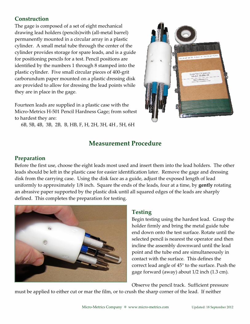
ConstructionThe gage is composed of a set of eight mechanical
drawing lead holders (pencils)with (all-metal barrel)
permanently mounted in a circular array in a plastic
cylinder. A small metal tube through the center of the
cylinder provides storage for spare leads, and is a guide
for positioning pencils for a test. Pencil positions are
identified by the numbers 1 through 8 stamped into the
plastic cylinder. Five small circular pieces of 400-grit
carborundum paper mounted on a plastic dressing disk
are provided to allow for dressing the lead points while
they are in place in the gage.
Fourteen leads are supplied in a plastic case with the
Micro-Metrics H-501 Pencil Hardness Gage; from softest
Carrying case: Cylindrical padded vinyl with snap top
References1. Smith, W.T., “Standardization of the Pencil Hardness Test,” Official Digest, 28, p. 232 ff (1956).
2. ASTM D3363, Method of Test for Film Hardness by Pencil Test.
3. Pencil Hardness Tests. Sherwin Williams Industrial Test Data Sheet TD-11.
4. NACE, TPC Publication No. 2, “Coatings and Linings for Immersion Service,” p. 22 (1972).
Micro-Metrics Company � www.micro-metrics.com Updated: 18 September 2012
OG202
Micro-Metrics CompanyProducts
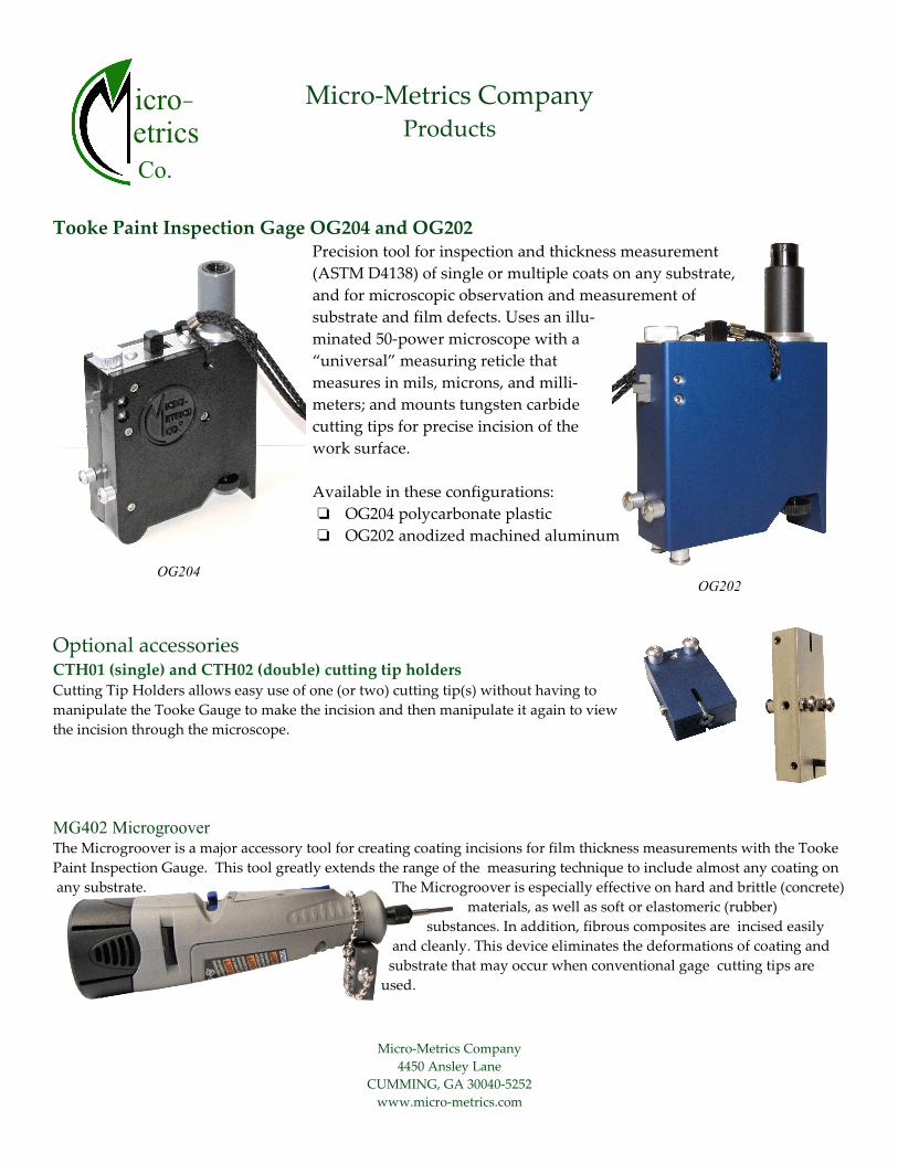
Tooke Paint Inspection Gage OG204 and OG202Precision tool for inspection and thickness measurement
(ASTM D4138) of single or multiple coats on any substrate,
and for microscopic observation and measurement of
substrate and film defects. Uses an illu-
minated 50-power microscope with a
“universal” measuring reticle that
measures in mils, microns, and milli-
meters; and mounts tungsten carbide
cutting tips for precise incision of the
work surface.
Available in these configurations:
� OG204 polycarbonate plastic
� OG202 anodized machined aluminum
Optional accessories CTH01 (single) and CTH02 (double) cutting tip holders Cutting Tip Holders allows easy use of one (or two) cutting tip(s) without having to
manipulate the Tooke Gauge to make the incision and then manipulate it again to view
the incision through the microscope.
MG402 Microgroover The Microgroover is a major accessory tool for creating coating incisions for film thickness measurements with the Tooke
Paint Inspection Gauge. This tool greatly extends the range of the measuring technique to include almost any coating on
any substrate. The Microgroover is especially effective on hard and brittle (concrete)
materials, as well as soft or elastomeric (rubber)
substances. In addition, fibrous composites are incised easily
and cleanly. This device eliminates the deformations of coating and
substrate that may occur when conventional gage cutting tips are