Product Data Sheet PS-00599, Rev. C April 2006 Micro Motion ® H-Series Hygienic Mass, Density, and Volume Meter With MVD ™ Technology • Mass flow accuracy to ±0.10%, volume flow accuracy to ±0.15%, and density accuracy to ±0.001 g/cc (±1.0 kg/m 3 ) on liquids • 32 Ra (0.8 µm) internal surface finish, with 15 Ra (0.4 µm) available • EHEDG approved and 3-A authorized • Self-draining • Optional secondary containment
Transcript
Product Data SheetPS-00599, Rev. CApril 2006
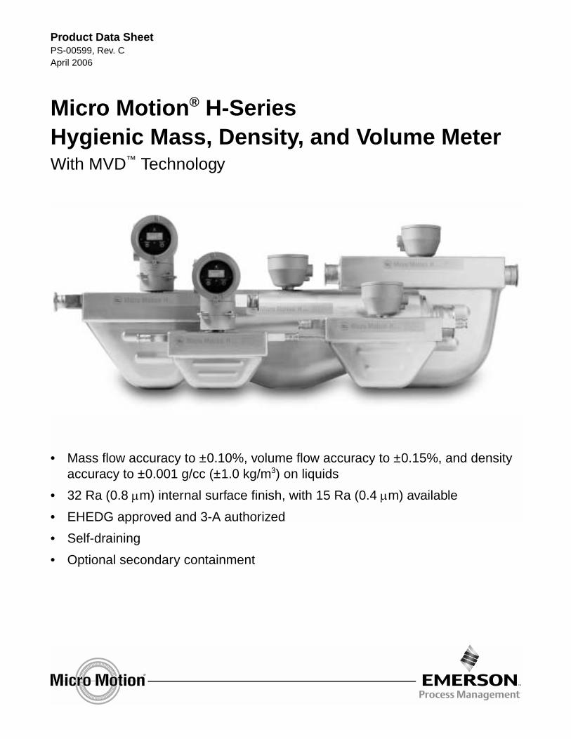
Micro Motion® H-SeriesHygienic Mass, Density, and Volume MeterWith MVD™ Technology
• Mass flow accuracy to ±0.10%, volume flow accuracy to ±0.15%, and density accuracy to ±0.001 g/cc (±1.0 kg/m3) on liquids
• 32 Ra (0.8 µm) internal surface finish, with 15 Ra (0.4 µm) available
• EHEDG approved and 3-A authorized
• Self-draining
• Optional secondary containment
2 Micro Motion® H-Series Hygienic Meter
Micro Motion® H-Series hygienic meter
Micro Motion H-Series meters offer highly accurate flow and density measurement for virtually any process fluid and with cleanability unmatched by any other dual-tube Coriolis flowmeter.
Hygienic standards
Micro Motion H-Series meters feature a 32 Ra (0.8 µm) internal surface finish, which is both 3-A authorized and EHEDG certified. All H-Series meters can be installed to be self-draining.
Micro Motion H-Series meters are also available with an improved surface finish option. This option provides a fully electro-polished flow path with an average surface finish of 15 Ra (0.4 µm).
3-A
Micro Motion H-Series meters are authorized to 3-A Sanitary Standards for Milk and Dairy Products.
EHEDG
Micro Motion H-Series meters are approved by the European Hygienic Equipment Design Group. H-Series sensors comply with the hygienic criteria of Machinery Directive 98/37/EC, annex 1 (additional essential health and safety requirements for certain categories of machinery), section 2.1 (agri-foodstuffs machinery). Test results show that Micro Motion H-Series sensors can be cleaned in place (CIP) at least as well as reference pipe.
ASME BPE
All Micro Motion H-Series meters are designed according to strict ASME guidelines for Bio-Processing Equipment.
Secondary containment
Micro Motion H-Series meters can be purchased with an optional secondary containment rating. This rating is supported by a pneumatic leak test of the sensor enclosure, along with documentation that describes how the safety of the sensor has been verified according to ASME B31.3 standards.
Product selector
Micro Motion offers an online product selector and configurator for finding the best products to fit your application. To use this program, visit our web site at www.micromotion.com.
(1) Volume measurement is based on a process-fluid density of 1 g/cc. For fluids with density other than 1 g/cc, the maximum volume flow rate equals the maximum mass flow rate divided by the fluid’s density.
lb/min kg/h gal/min l/h
Maximum flow rate H025 76 2068 9 2068
H050 180 4900 22 4900
H100 820 22,320 98 22,320
H200 2350 63,960 282 63,960
H300 10,000 272,000 1200 272,000
Mass flow accuracy(2)
(2) Stated flow accuracy includes the combined effects of repeatability, linearity, and hysteresis.
Transmitter with MVD Technology
±0.10% of rate(3)(4)
(3) When flow rate < (zero stability / 0.001), then mass flow accuracy = ±[(zero stability / flow rate) × 100]% of rate and repeatability = ±[½(zero stability / flow rate) × 100]% of rate.
(4) When ordered with the ±0.15% calibration option, mass flow accuracy on liquid = ±0.15% when flow rate ≥ (zero stability / 0.0015). When flow rate < (zero stability / 0.0015), then accuracy = ±[(zero stability / flow rate) × 100]% of rate.
All other transmitters(5)
(5) Model H300 sensors are only compatible with MVD Technology transmitters.
±0.15% of rate ±[(zero stability / flow rate) × 100]% of rate
Volume flow accuracy(2) Transmitter with MVD Technology
±0.15% of rate(6)(7)
(6) When flow rate < (zero stability / 0.001), then volume flow accuracy on liquid = ±[1.5 × (zero stability / flow rate) × 100]% of rate and repeatability = ±[½(zero stability / flow rate) × 100]% of rate.
(7) When ordered with the ±0.15% calibration option, volume flow accuracy on liquid = ±0.25% when flow rate ≥ (zero stability / 0.0017). When flow rate < (zero stability / 0.0017), then volume accuracy on liquid = ±[1.5 × (zero stability / flow rate) × 100]% of rate.
Repeatability Transmitter with MVD Technology
±0.05% of rate(3)
All other transmitters ±0.10% of rate ±[½(zero stability / flow rate) × 100]% of rate
lb/min kg/h gal/min l/h
Zero stability H025 0.0065 0.1765 0.0008 0.1765
H050 0.020 0.544 0.002 0.544
H100 0.080 2.177 0.010 2.177
H200 0.256 6.965 0.031 6.965
H300 0.80 21.76 0.096 21.76
4 Micro Motion® H-Series Hygienic Meter
Liquid flow performance continued
Density performance (liquid only)
Typical accuracy, turndown, and pressure drop with transmitter with MVD Technology
To determine accuracy, turndown, and pressure drop with your process variables, use the Micro Motion product selector and configurator, available at www.micromotion.com.
Turndown 40:1 20:1 2:1
Accuracy (± %) 0.26 0.13 0.10
Pressure drop
psi 0.1 0.3 14.2
bar 0.01 0.02 0.98
Accuracy(1)
(1) Stated accuracy and repeatability with calibration option 1 (see page 24). With other calibration options, accuracy is ±0.002 g/cm3 (2.0 kg/m3) and repeatability is ±0.001 g/cm3 (±1.0 kg/m3).
±0.001 g/cm3 ±1.0 kg/m3
Repeatability ±0.0005 g/cm3 ±0.5 kg/m3
Range Up to 5 g/cm3 Up to 5000 kg/m3
Flow rate, % of maximum
Acc
ura
cy, %
–1.0
–0.8
–0.6
–0.4
–0.2
0
0.2
0.4
0.6
0.8
1.0
0 100908070605040302010
40:1
20:1
1:12:1
Micro Motion® H-Series Hygienic Meter 5
Gas flow performance
When selecting sensors for gas applications, measurement accuracy is a function of fluid mass flow rate independent of operating temperature, pressure, or composition. However, pressure drop through the sensor is dependent upon operating temperature, pressure, and fluid composition. Therefore, when selecting a sensor for any particular gas application, it is highly recommended that each sensor be sized using Micro Motion’s product selector, available at www.micromotion.com.
Mass Volume(1)
(1) Standard (SCFM) reference conditions are 14.7 psia and 68 °F. Normal (Nm3/h) reference conditions are 1.013 bar and 0 °C.
lb/min kg/h SCFM Nm3/h
Typical flow rates that produce approximately 10 psid (0.68 bar) pressure drop on air at 68 °F (20 °C) and 100 psi (6.8 bar)
Typical accuracy and pressure drop with H100 with MVD Technology
Air at 68 °F (20 °C), static pressures as indicated on graph
Natural gas (MW 16.675) at 68 °F (20 °C), static pressures as indicated on graph
Standard or Normal Volumetric CapabilityStandard and normal volumes are “quasi mass” flow units for any fixed composition fluid. Standard and normal volumes do not vary with operating pressure, temperature, or density. With knowledge of density at standard or normal conditions (available from reference sources), a Micro Motion meter can be configured to output in standard or normal volume units without the need for pressure, temperature, or density compensation. Contact your local sales representative for more information.
bar inches H2Opsig
20
15
10
5
0
1.5
1.0
0.5
0
600
500
400
300
200
100
00
0.5
1.0
1.5
2.0
0 20 40 60 80 100 120 140 160
0 1000 2000 3000 4000
Flow rate
Acc
ura
cy (
± %
of
rate
)
100 psi(7 bar)
500 psi(35 bar)
1000 psi(70 bar)
lb/min
kg/h
Pre
ssu
re d
rop
bar inches H2Opsig
20
15
10
5
0
1.5
1.0
0.5
0
600
500
400
300
200
100
00
0.5
1.0
1.5
2.0
0 20 40 60 80 100 120 140 160
0 1000 2000 3000 4000
Flow rate
Acc
ura
cy (
± %
of
rate
)
100 psi(7 bar)
500 psi(35 bar)
1000 psi(70 bar)
lb/min
kg/h
Pre
ssu
re d
rop
Micro Motion® H-Series Hygienic Meter 7
Temperature specifications
Accuracy All models ±1 °C ± 0.5% of reading in °C
Repeatability All models ±0.2 °C
Temperature limits(1)
(1) Temperature limits may be further restricted by hazardous area approvals. See pages 10–16.
All models with all electronics options (except the IFT9701 transmitter) (2)(3)
(2) The difference in temperature between the process fluid and the case cannot exceed 120 °F (66 °C) for H300 sensors.
(3) The temperature extender option allows the sensor case to be insulated without covering the transmitter, core processor, or junction box, but does not affect temperature ratings.
Sensors with integral IFT9701 transmitter(4)
(4) Refer to the IFT9701 Product Data Sheet for more information about its temperature limits.
Ambient temperature:+131 °F (+55 °C) maximum
Process temperature:+257 °F (+125 °C) maximum
Am
bien
t tem
pera
ture
in °
F (
°C)
Process fluid temperature °F (°C)
Mount electronics remotely; use j-box
–148 (–100)
–112 (–80)
–76 (–60)
–40 (–40)
–4 (–20)
32 (0)
68 (20)
104 (40)
140 (60)
176 (80)
–148
(–1
00)
–76
(–60
)
–4 (
–20)
68 (
20)
140
(60)
248
(120
)
91 (33)
–58 (–50)
Mount electronics remotely; use j-box*
* When ambient temperature is below –58 °F (–50 °C), a core processor must be heated to bring its local ambient temperature to between –58 °F (–50 °C) and +140 °F (+60 °C). Long-term storage of electronics at ambient temperatures below –58 °F (–50 °C) is not recommended.
158 (70)
392
(200
)
–112
(–8
0)
–40
(–40
)
32 (
0)
104
(40)
212
(100
)
284
(140
)
320
(160
)
356
(180
)
176
(80)
8 Micro Motion® H-Series Hygienic Meter
Pressure ratings
Vibration limits
psi bar
Flow tube rating(1)
(1) Pressure rating at 77 °F (25 °C), according to ASME B31.3. For temperatures above 300 °F (148 °C), pressure needs to be derated as follows. Linear interpolation may be used between specified temperatures.
Sensor with standard surface finish 1450 100
Sensor with improved surface finish 1015 70
PED compliance Sensors comply with council directive 97/23/EC of 29 May 1997 on Pressure Equipment
ASME B31.3 secondary containment rating(1)
Burst pressure used to determine ASME B31.3 secondary containment rating
psi bar psi bar
Housing rating(2)
(2) Sensor housing is only rated when the secondary containment case option is purchased.
H025 166 11.4 1884 130
H050 135 9.3 1530 105
H100 109 7.5 1281 88.3
H200 64 4.4 760 52.4
H300 256 17.7 2630 180
Meets IEC 68.2.6, endurance sweep, 5 to 2000 Hz, 50 sweep cycles at 1.0 g
Flow tubes (316L sensors) Housing (all sensors)up to 300 °F (up to 148 °C) None None
at 400 °F (204 °C) 7.2% derating 5.4% derating
Micro Motion® H-Series Hygienic Meter 9
Environmental effects
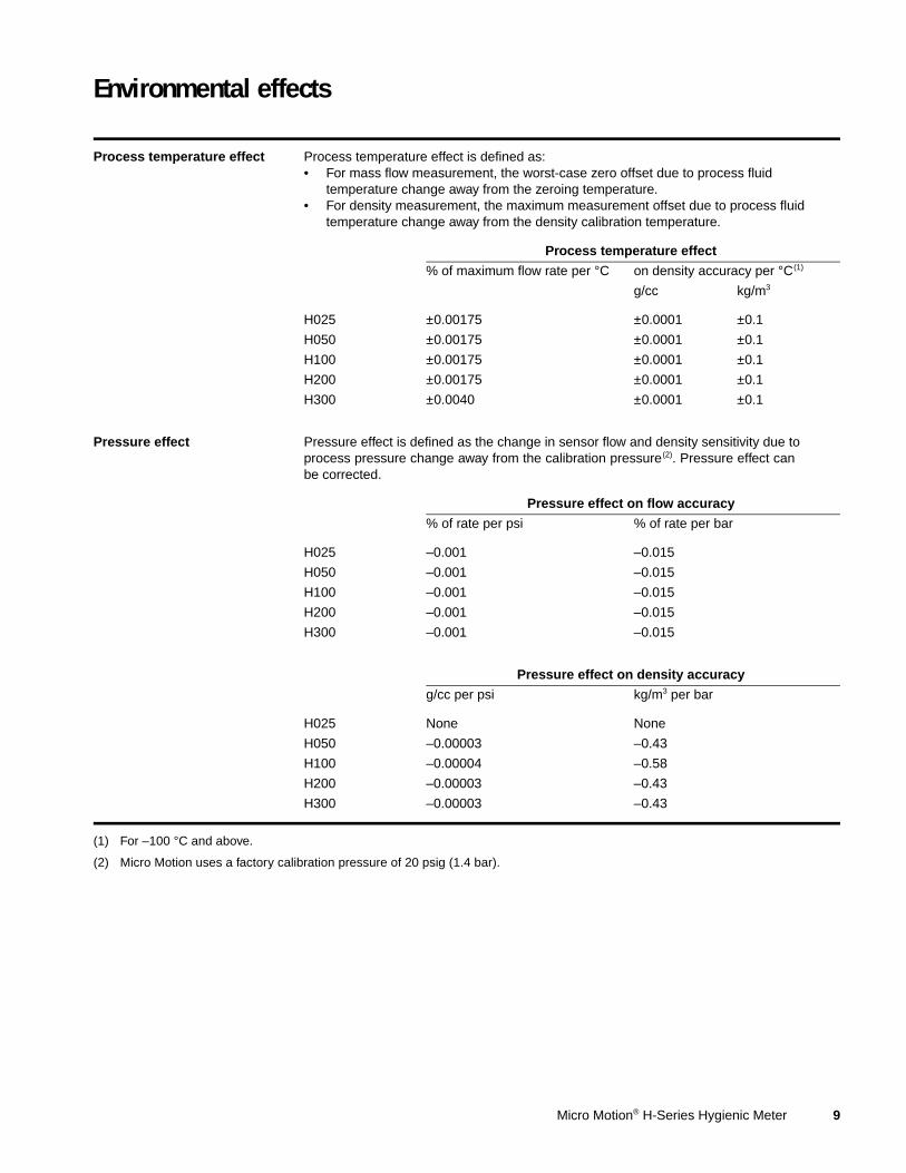
Process temperature effect Process temperature effect is defined as:• For mass flow measurement, the worst-case zero offset due to process fluid
temperature change away from the zeroing temperature.• For density measurement, the maximum measurement offset due to process fluid
temperature change away from the density calibration temperature.
Process temperature effect
% of maximum flow rate per °C on density accuracy per °C(1)
(1) For –100 °C and above.
g/cc kg/m3
H025 ±0.00175 ±0.0001 ±0.1
H050 ±0.00175 ±0.0001 ±0.1
H100 ±0.00175 ±0.0001 ±0.1
H200 ±0.00175 ±0.0001 ±0.1
H300 ±0.0040 ±0.0001 ±0.1
Pressure effect Pressure effect is defined as the change in sensor flow and density sensitivity due to process pressure change away from the calibration pressure(2). Pressure effect can be corrected.
(2) Micro Motion uses a factory calibration pressure of 20 psig (1.4 bar).
Pressure effect on flow accuracy
% of rate per psi % of rate per bar
H025 –0.001 –0.015
H050 –0.001 –0.015
H100 –0.001 –0.015
H200 –0.001 –0.015
H300 –0.001 –0.015
Pressure effect on density accuracy
g/cc per psi kg/m3 per bar
H025 None None
H050 –0.00003 –0.43
H100 –0.00004 –0.58
H200 –0.00003 –0.43
H300 –0.00003 –0.43
10 Micro Motion® H-Series Hygienic Meter
Hazardous area classifications
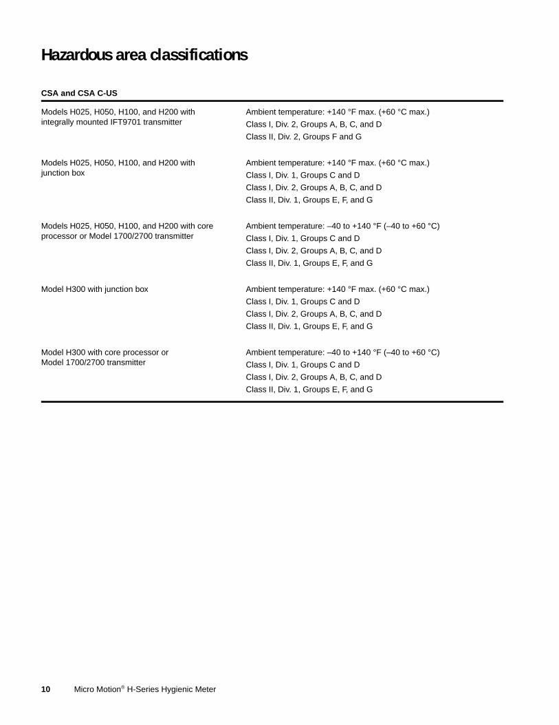
CSA and CSA C-US
Models H025, H050, H100, and H200 with integrally mounted IFT9701 transmitter
Ambient temperature: +140 °F max. (+60 °C max.)
Class I, Div. 2, Groups A, B, C, and D
Class II, Div. 2, Groups F and G
Models H025, H050, H100, and H200 with junction box
Ambient temperature: +140 °F max. (+60 °C max.)
Class I, Div. 1, Groups C and D
Class I, Div. 2, Groups A, B, C, and D
Class II, Div. 1, Groups E, F, and G
Models H025, H050, H100, and H200 with core processor or Model 1700/2700 transmitter
Ambient temperature: –40 to +140 °F (–40 to +60 °C)
Class I, Div. 1, Groups C and D
Class I, Div. 2, Groups A, B, C, and D
Class II, Div. 1, Groups E, F, and G
Model H300 with junction box Ambient temperature: +140 °F max. (+60 °C max.)
Class I, Div. 1, Groups C and D
Class I, Div. 2, Groups A, B, C, and D
Class II, Div. 1, Groups E, F, and G
Model H300 with core processor or Model 1700/2700 transmitter
Ambient temperature: –40 to +140 °F (–40 to +60 °C)
Class I, Div. 1, Groups C and D
Class I, Div. 2, Groups A, B, C, and D
Class II, Div. 1, Groups E, F, and G
Micro Motion® H-Series Hygienic Meter 11
Hazardous area classifications continued
ATEX(1)
(1) ATEX “T” rating depends on the maximum temperature shown in the graphs above.
Models H025, H050, H100, and H200 with integral core processor or Model 1700/2700 transmitter
Transmitter with display:
0575 II 2 (1) G EEx ib IIB+H2 T1–5
II 2 D IP65 T °C
Core processor or transmitter without display:
0575 II 2 G EEx ib IIC T1–T5
II 2 D IP65 T °C
Max
. am
bie
nt
tem
per
atu
re (
°C)
Sensor fluid temperature (°C)
De-rate at slope = –0.25 °C per °C fluid
The maximum surface temperature for dust is as follows: T5:T 95 °C, T4:T 130 °C, T3–T1:T 183 °C.
H025 and H050 with C.I.C. A2
Max
. am
bie
nt
tem
per
atu
re (
°C)
Sensor fluid temperature (°C)
De-rate at slope = –0.25 °C per °C fluid
The maximum surface temperature for dust is as follows: T5:T 95 °C, T4:T 130 °C, T3:T 195 °C, T2–T1:T 216°C.
H100 with C.I.C. A2
Max
. am
bie
nt
tem
per
atu
re (
°C)
Sensor fluid temperature (°C)
De-rate at slope = –0.25 °C per °C fluid
The maximum surface temperature for dust is as follows: T5:T 95 °C, T4:T 130 °C, T3:T 195 °C, T2 to T1:T 206 °C.
H200 with C.I.C. A1
12 Micro Motion® H-Series Hygienic Meter
Hazardous area classifications continued
ATEX(1)
(1) ATEX “T” rating depends on the maximum temperature shown in the graphs above.
Models H025, H050, H100, and H200 with junction box when connected to an MVD transmitter
0575 II 2 G EEx ib IIC T1–T6
II 2 D IP65 T °C
Max
. am
bie
nt
tem
per
atu
re (
°C)
Sensor fluid temperature (°C)
The maximum surface temperature for dust is as follows: T6:T 80 °C, T5:T 95 °C, T4:T 130 °C, T3–T1:T 183 °C. The minimum process and ambient temperature for dust is –40 °C.
H025 and H050 with C.I.C. A2
Max
. am
bie
nt
tem
per
atu
re (
°C)
Sensor fluid temperature (°C)
The maximum surface temperature for dust is as follows: T6:T 80 °C, T5:T 95 °C, T4:T 130 °C, T3:T 195 °C, T2 to T1:T 216 °C. The minimum process and ambient temperature for dust is –40 °C.
H100 with C.I.C. A2
Max
. am
bie
nt
tem
per
atu
re (
°C)
Sensor fluid temperature (°C)
The maximum surface temperature for dust is as follows: T6:T 80 °C, T5:T 95 °C, T4:T 130 °C, T3:T 195 °C, T2 to T1:T 202 °C. The minimum process and ambient temperature for dust is –40 °C.
H200 with C.I.C. A1
Micro Motion® H-Series Hygienic Meter 13
Hazardous area classifications continued
ATEX(1)
(1) ATEX “T” rating depends on the maximum temperature shown in the graphs above.
Models H025, H050, H100, and H200 with junction box when connected to a non-MVD transmitter
0575 II 2 G EEx ib IIC T1–T6
II 2 D IP65 T °C
Max
. am
bie
nt
tem
per
atu
re (
°C)
Sensor fluid temperature (°C)
The maximum surface temperature for dust is as follows: T6:T 80 °C, T5:T 95 °C, T4:T 130 °C, T3–T1:T 183 °C. The minimum process and ambient temperature for dust is –40 °C.
H025 and H050 with C.I.C. A2
Max
. am
bie
nt
tem
per
atu
re (
°C)
Sensor fluid temperature (°C)
The maximum surface temperature for dust is as follows: T6:T 80 °C, T5:T 95 °C, T4:T 130 °C, T3:T 195 °C, T2 to T1:T 216 °C. The minimum process and ambient temperature for dust is –40 °C.
H100 with C.I.C. A2
Max
. am
bie
nt
tem
per
atu
re (
°C)
Sensor fluid temperature (°C)
The maximum surface temperature for dust is as follows: T6:T 80 °C, T5:T 95 °C, T4:T 130 °C, T3:T 195 °C, T2 to T1:T 202 °C. The minimum process and ambient temperature for dust is –40 °C.
H200 with C.I.C. A1
14 Micro Motion® H-Series Hygienic Meter
Hazardous area classifications continued
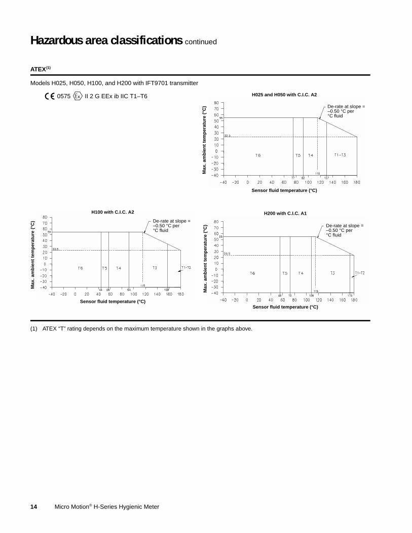
ATEX(1)
(1) ATEX “T” rating depends on the maximum temperature shown in the graphs above.
Models H025, H050, H100, and H200 with IFT9701 transmitter
0575 II 2 G EEx ib IIC T1–T6
Max
. am
bie
nt
tem
per
atu
re (
°C)
Sensor fluid temperature (°C)
De-rate at slope = –0.50 °C per °C fluid
H025 and H050 with C.I.C. A2
Max
. am
bie
nt
tem
per
atu
re (
°C)
Sensor fluid temperature (°C)
De-rate at slope = –0.50 °C per °C fluid
H100 with C.I.C. A2
Max
. am
bie
nt
tem
per
atu
re (
°C)
Sensor fluid temperature (°C)
De-rate at slope = –0.50 °C per °C fluid
H200 with C.I.C. A1
Micro Motion® H-Series Hygienic Meter 15
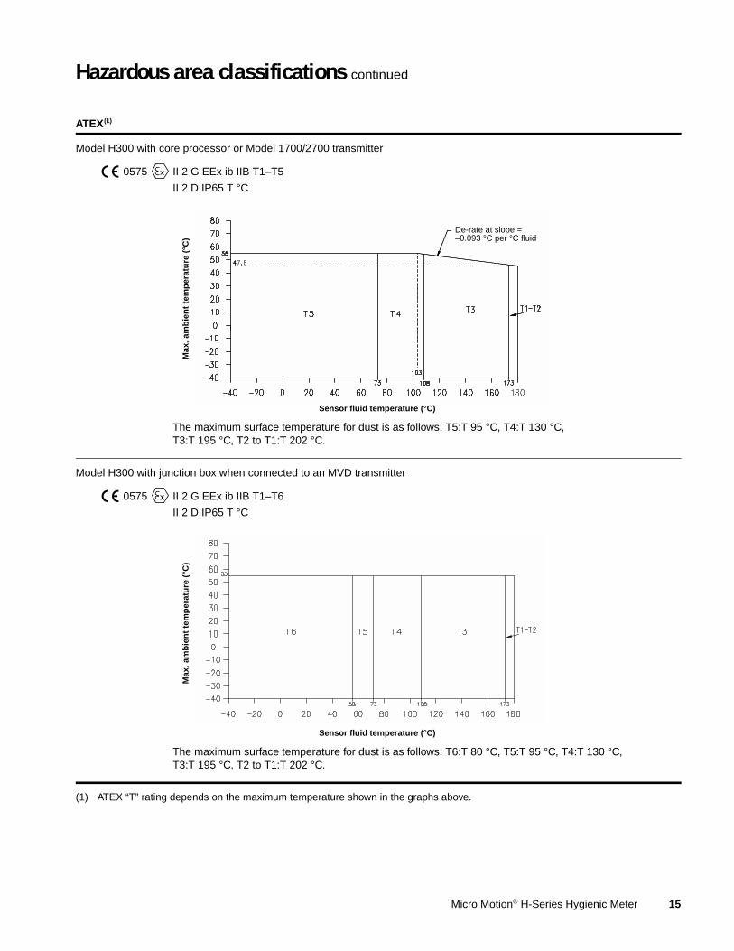
Hazardous area classifications continued
ATEX(1)
(1) ATEX “T” rating depends on the maximum temperature shown in the graphs above.
Model H300 with core processor or Model 1700/2700 transmitter
0575 II 2 G EEx ib IIB T1–T5
II 2 D IP65 T °C
The maximum surface temperature for dust is as follows: T5:T 95 °C, T4:T 130 °C, T3:T 195 °C, T2 to T1:T 202 °C.
Model H300 with junction box when connected to an MVD transmitter
0575 II 2 G EEx ib IIB T1–T6
II 2 D IP65 T °C
The maximum surface temperature for dust is as follows: T6:T 80 °C, T5:T 95 °C, T4:T 130 °C, T3:T 195 °C, T2 to T1:T 202 °C.
Max
. am
bie
nt
tem
per
atu
re (
°C)
Sensor fluid temperature (°C)
De-rate at slope = –0.093 °C per °C fluid
Max
. am
bie
nt
tem
per
atu
re (
°C)
Sensor fluid temperature (°C)
16 Micro Motion® H-Series Hygienic Meter
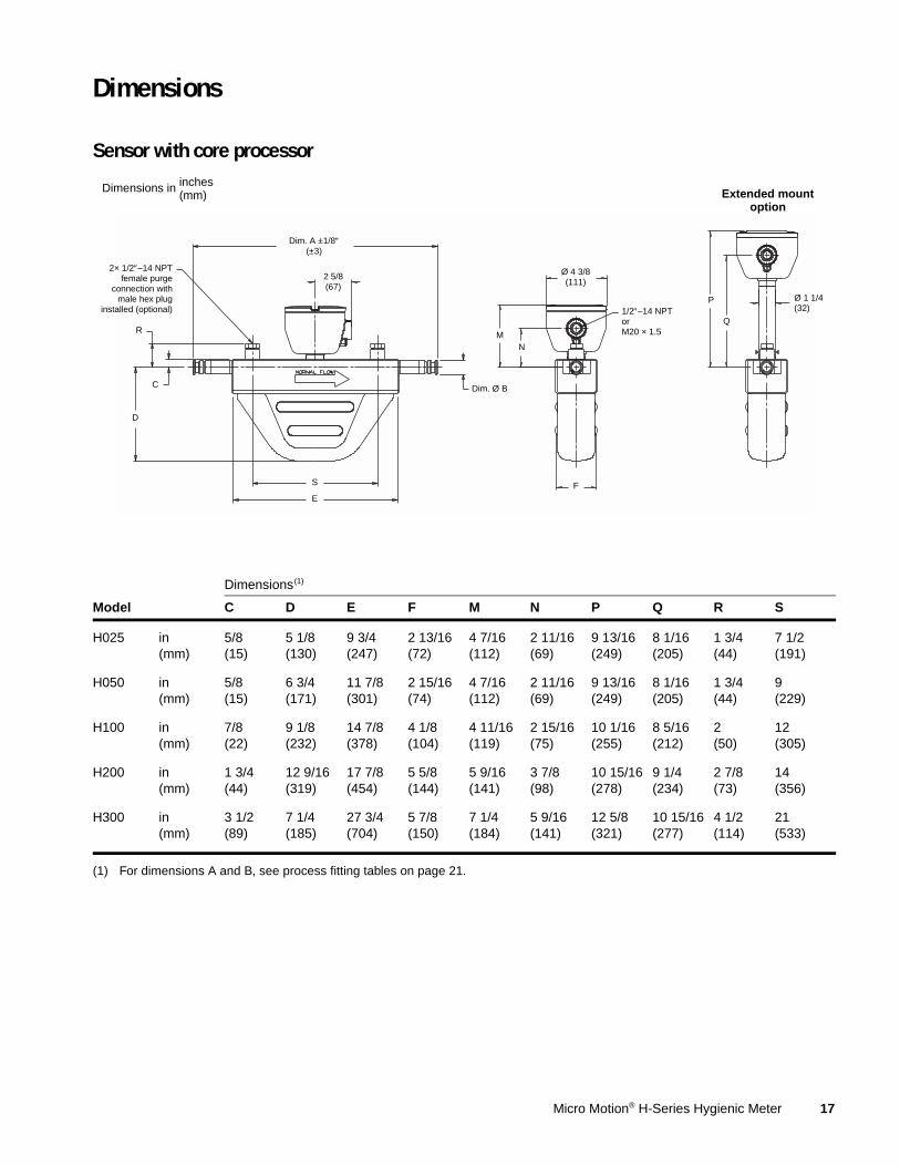
Materials of construction
Weight
Wetted parts(1)
(1) General corrosion guidelines do not account for cyclical stress, and therefore should not be relied upon when choosing a wetted material for your Micro Motion flowmeter. Please refer to Micro Motion’s corrosion guide for material compatibility information.
Sensor with standard surface finish
316L stainless steel, 32 Ra (0.8 µm) surface finish
Sensor with improved surface finish
316L stainless steel, 15 Ra (0.4 µm) electro-polished surface finish
Junction box Polyurethane-painted aluminum; NEMA 4X (IP 65)
Weights provided are the weight of the flowmeter with sanitary fittings.
H025 H050 H100 H200 H300
lb kg lb kg lb kg lb kg lb kg
Sensor with integrally mountedIFT9701 transmitter
14 7 16 7 24 11 47 21 — —
Sensor with integrally mountedcore processor(1)
(1) Weights given are for sensor with stainless steel core processor. Subtract 4 lb (2 kg) for aluminum core housing option (electronics interface codes Q, V, W, and Y).
13 6 15 7 23 11 42 19 136 62
Sensor with extendedcore processor(1)
14 7 16 7 24 11 43 20 137 62
Sensor with integrally mountedModel 1700 or 2700 transmitter
P Secondary containment with test report and purge fittings (1/2-inch NPT female)
Code Electronics interface
Q 4-wire polyurethane-painted aluminum integral core processor for remotely mounted transmitter with MVD Technology
A 4-wire stainless steel integral core processor for remotely mounted transmitter with MVD Technology
V 4-wire polyurethane-painted aluminum integral core processor with extended mount for remotely mounted transmitter with MVD Technology
B 4-wire stainless steel integral core processor with extended mount for remotely mounted transmitter withMVD Technology
C Integrally mounted Model 1700 or 2700 transmitter
W(1)
(1) When electronics interface W, D, Y, or E is ordered with approval codes C, A, or Z, an MVD Direct Connect I.S. barrier is supplied. No barrier is supplied when ordered with approval codes M or N.
Polyurethane-painted aluminum integral core processor for MVD Direct Connect™ installations
D(1) Stainless steel integral core processor for MVD Direct Connect installations
Y(1) Polyurethane-painted aluminum integral core processor with extended mount for MVD Direct Connect installations
E(1) Stainless steel integral core processor with extended mount for MVD Direct Connect installations
I(2)
(2) Not available with Model H300.
Integrally mounted IFT9701 transmitter
R 9-wire polyurethane-painted aluminum junction box
H 9-wire polyurethane-painted aluminum junction box with extended mount
Continued on next page
Micro Motion® H-Series Hygienic Meter 23
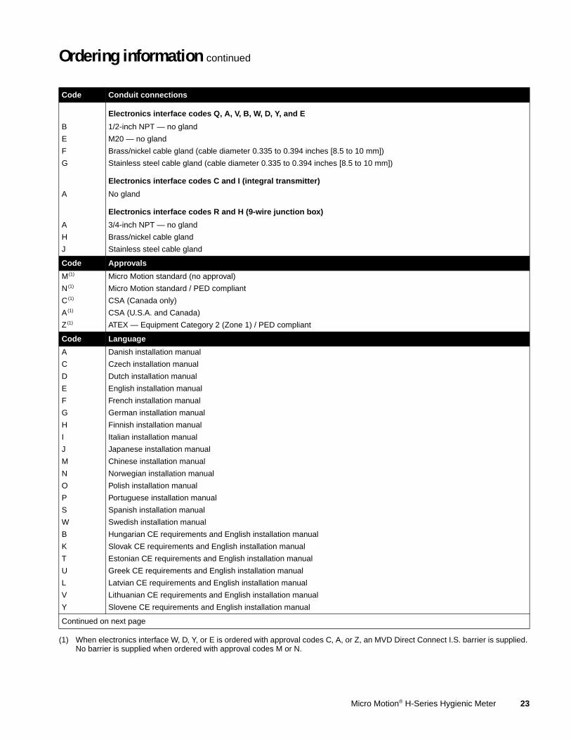
Ordering information continued
Code Conduit connections
Electronics interface codes Q, A, V, B, W, D, Y, and E
B 1/2-inch NPT — no gland
E M20 — no gland
F Brass/nickel cable gland (cable diameter 0.335 to 0.394 inches [8.5 to 10 mm])
G Stainless steel cable gland (cable diameter 0.335 to 0.394 inches [8.5 to 10 mm])
Electronics interface codes C and I (integral transmitter)
A No gland
Electronics interface codes R and H (9-wire junction box)
A 3/4-inch NPT — no gland
H Brass/nickel cable gland
J Stainless steel cable gland
Code Approvals
M(1)
(1) When electronics interface W, D, Y, or E is ordered with approval codes C, A, or Z, an MVD Direct Connect I.S. barrier is supplied. No barrier is supplied when ordered with approval codes M or N.
Due to Micro Motion’s commitment to continuous improvement of our products, all specifications are subject to change without notice. ELITE, ProLink, and the Micro Motion logo are registered trademarks, and MVD and MVD Direct Connect are trademarks of Micro Motion, Inc., Boulder, Colorado. The Emerson logo is a trademark of Emerson Electric Co. All other trademarks are property of their respective owners.
For the latest Micro Motion product specifications, view the PRODUCTS section of our web site at www.micromotion.com