MICROCHANNELS IN MACRO THERMAL MANAGEMENT SOLUTIONS by Boris V. KOSOY Original scientific paper UDC: 532.546:519.876.5:66.045.1 BIBLID: 0354-9836, 10 (2006), 1, 81-98 Modern progress in electronics is associated with increase in computing ability and processing speed, as well as decrease in size. Future applica- tions of electronic devices in aviation, aerospace and high performance consumer products’ industry demand on very stringent specifications con- cerning miniaturization, component density, power density and reliability. Excess heat produces stresses on internal components inside the electronic device, thus creating reliability problems. Thus, a problem of heat genera- tion and its efficient removal arises and it has led to the development of ad- vanced thermal control systems. Present research analyses a thermody- namic feasibility of micro capillary heat pumped networks in thermal management of electronic systems, considers basic technological con- strains and design availability, and identifies perspective directions for the further studies. Computer Fluid Dynamics studies have been performed on the laminar con- vective heat transfer and pressure drop of working fluid in silicon micro- -channels. Surface roughness is simulated via regular, constructal, and sto- chastic models. Three-dimensional numerical solution shows significant ef- fects of surface roughness in terms of the rough element geometry such as height, size, spacing and the channel height on the velocity and pressure fields. Key words: micro-channels, roughness, computer fluid dynamics, con- structal principle, micro-capillary heat pumping networks, thermal management Introduction Thermal management is a crucial facilitating technology in the development of modern electronics. It has enabled many of the so-called Moore’s law advances in com- puters and microelectronics, which took place in the last years. As the power supplied to electronic packages and microelectromechanical system (MEMS) type devices in- creases, the problem of thermal control becomes critical. Assembly and packaging tech- nologies are being driven to simultaneously meet very demanding requirements in the ar- eas of performance, power, junction temperature, package geometry, and cost. These demands, plus increased reliability expectations, will push the cooling and packaging 81
Transcript
MICROCHANNELS IN MACRO THERMAL
MANAGEMENT SOLUTIONS
by
Boris V. KOSOY
Original scientific paperUDC: 532.546:519.876.5:66.045.1
BIBLID: 0354-9836, 10 (2006), 1, 81-98
Mod ern prog ress in elec tron ics is as so ci ated with in crease in com put ingabil ity and pro cess ing speed, as well as de crease in size. Fu ture ap pli ca -tions of elec tronic de vices in avi a tion, aero space and high per for mancecon sumer prod ucts’ in dus try de mand on very strin gent spec i fi ca tions con -cern ing min ia tur iza tion, com po nent den sity, power den sity and re li abil ity.Ex cess heat pro duces stresses on in ter nal com po nents in side the elec tronicde vice, thus cre at ing re li abil ity prob lems. Thus, a prob lem of heat gen er a -tion and its ef fi cient re moval arises and it has led to the de vel op ment of ad -vanced ther mal con trol sys tems. Pres ent re search anal y ses a ther mo dy -namic fea si bil ity of mi cro cap il lary heat pumped net works in ther malman age ment of elec tronic sys tems, con sid ers ba sic tech no log i cal con -strains and de sign avail abil ity, and iden ti fies per spec tive di rec tions for thefur ther stud ies.Com puter Fluid Dy nam ics stud ies have been per formed on the lam i nar con -vec tive heat trans fer and pres sure drop of work ing fluid in sil i con mi cro--chan nels. Sur face rough ness is sim u lated via reg u lar, constructal, and sto -chas tic mod els. Three-di men sional nu mer i cal so lu tion shows sig nif i cant ef -fects of sur face rough ness in terms of the rough el e ment ge om e try such asheight, size, spac ing and the chan nel height on the ve loc ity and pres surefields.
Key words: mi cro-chan nels, rough ness, com puter fluid dy nam ics, con-structal prin ci ple, mi cro-cap il lary heat pump ing net works,ther mal man age ment
Introduction
Ther mal man age ment is a cru cial fa cil i tat ing tech nol ogy in the de vel op ment ofmod ern elec tron ics. It has en abled many of the so-called Moore’s law ad vances in com -put ers and mi cro elec tron ics, which took place in the last years. As the power sup plied toelec tronic pack ages and microelectromechanical sys tem (MEMS) type de vices in -creases, the prob lem of ther mal con trol be comes crit i cal. As sem bly and pack ag ing tech -nol o gies are be ing driven to si mul ta neously meet very de mand ing re quire ments in the ar -eas of per for mance, power, junc tion tem per a ture, pack age ge om e try, and cost. Thesede mands, plus in creased re li abil ity ex pec ta tions, will push the cool ing and pack ag ing
81
lim its of elec tronic prod ucts. Con ven tional meth ods of heat re moval are sim ply not ca pa -ble to deal with the ther mal gra di ents, which lead to ma te rial fail ure. It there fore be comes nec es sary to look be yond tra di tional ther mal man age ment so lu tions.
From this point of view, liq uid-va por phase change, di rect and in di rect liq uidcool ing, im ping ing jets, drop lets, and sprays are at trac tive cool ing op tions for re mov inghigh heat fluxes be cause of their as so ci ated heat trans fer co ef fi cients. Liq uid cool ingwith boil ing has been ex ten sively stud ied in the past, start ing with the pi o neer ing worksof Park and Bergles [1], Carvalho and Bergles [2], Bergles and Bar-Co hen [3], Incropera[4], and Bar-Co hen [5]. The main is sues in ves ti gated are the crit i cal heat flux lev els thatcan be at tained, tem per a ture over shoot and in cip i ent ex cur sion, bub ble growth and de -par ture as well as the ef fect of sur face en hance ment. Ma et al. pres ent an ex ten sive lit er a -ture sur vey of jet im pinge ment cool ing with and with out boil ing, [6]. En hanced sur faceshave been in ves ti gated at length by Ravigururajan and Bergles [7] and sev eral other re -search ers, and cor re spond ing sur veys have been pub lished by Webb [8]. En hanced sur -faces have proven suc cess ful in in duc ing higher heat trans fer rates and lower tem per a ture over shoots in pool and jet im pinge ment boil ing. In the con text of elec tron ics cool ing,Nakayama et al. [9] in ves ti gated the ef fect of nu cle ation sites and de signed en hanced sur -faces that achieved crit i cal heat fluxes above 100 W/cm2 with flu o ri nate di elec tric liq -uids. In this re spect Amon et al. [10] de ter mined the op ti mal con fig u ra tion of mi -cro-struc tured sil i con sur faces, which could be used as the heat spread ers.
Ef fec tive in di rect liq uid cool ing with two-phase heat trans fer has been re al izedby means of heat pipes and thermosyphons, [11]. Thus, due to the lim ited space andpower avail able in laptops, heat pipes are ide ally suited for cool ing the high power chips.Three or four mil li me ter di am e ter mi cro heat pipes can ef fec tively re move the high fluxheat from the pro ces sor and spread the heat load over a rel a tively large area heat sink,where the heat flux is so low that it can be ef fec tively dis si pated through the note bookcase to the am bi ent air. More over, mod ern trends within the sub se quent wick pump ingtech nol ogy make the per spec tive of Mi cro-Cap il lary Heat Pumped Net works(MCHPN’s) for ther mal man age ment of elec tron ics both prom is ing and re al is tic, [12].
Ba si cally, two-phase heat trans fer, in volv ing evap o ra tion of a liq uid in a hot re -gion and con den sa tion of va por in a cold re gion, can pro vide the re moval of much higherheat fluxes than can be achieved through con ven tional forced air-cool ing, which is therea son why con sid er able re search has been re di rected to wards these ap proaches for ther -mal man age ment of elec tron ics. There fore, in re cent years the en tire group of de vices,based on the use of fea tures and ad van tages of two-phase heat trans fer in cap il lary-po -rous struc tures has been cre ated. Since ma jor ity of the de vices re lated to this group hasbeen de vel oped rather re cently, their stud ies ba si cally have con stricted ex per i men talback ground, di rected to study ing of dis tinc tive prin ci ples of heat and mass trans fer. Thisstate ment rep re sents an es sen tial draw back for ex e cu tion of the de tailed ther mo dy namicde sign of such sys tems and the re spec tive ther mo dy namic op ti mi za tion. From this pointof view the goal of the pres ent pa per is not a raw at tempt to sug gest a pan a cea for the res o -lu tion of all prob lems in the ap pli ca tion of the MCHPN’s at one stroke, but to ar range there spec tive ac cents, al low ing as to over come a gap within con ven tional meth ods of thether mo dy namic anal y sis of cool ing sys tems, and to cre ate pre con di tions for its fur ther de -
82
THERMAL SCIENCE: Vol. 10 (2006), No. 1, pp. 81-98
vel op ment. Sub se quently, first we shall list some im por tant fea tures of cap il lary-po rousstruc tures, mak ing them as at trac tive con struc tion el e ment for the pres ent and fu ture ther -mal man age ment sys tems.
Capillary-porous structures
Many nat u ral ma te ri als fall in the cat e gory of po rous me dia, e. g., rocks, sands,soils, woods, etc. [13]. Many struc tures made of packed or sintered solid par ti cles, suchas sphere packs or fi ber mats, and foams are ar ti fi cial po rous me dia, com monly used inmany in dus trial pro cesses, e. g., heat trans fer, gas sep a ra tion, pe tro leum en gi neer ing, etc.As a mat ter of fact, al most all nat u ral and ar ti fi cial ma te ri als are po rous, in some sense,100% per fect solid ma te rial is hardly ex is tent. The term po rous solid is even used to de -note crys tal struc tures with mo lec u lar-level pores that al low trans por ta tion of mol e culesthrough those small pores. Hence, par tic u lar mag ni tude of po rous me dia in many in dus -trial pro cesses (e. g. heat trans fer, cat a lyst, dis til la tion, etc.) is due to the ex is tence ofpores.
The pore is a void space, which is not oc cu pied by solid. A quan ti ta tive mea surefor the amount of pore space in a ma te rial is po ros ity, which is de fined by a ra tio of thevoid space, Vp, to nom i nal solid space, V V / V .p, e = Through these pores, flu ids can betrans ported in va por or liq uid phase. Due to the com plex ity of pore struc ture, mass trans -port oc curs through com plex path com posed of many pores. The ex is tence of pores in asolid fa cil i tates fast heat trans fer or chem i cal re ac tion by in creas ing the con tact area be -tween solid and fluid. The spe cific solid/fluid sur face area, A12/V is much larger thannom i nal sur face area, and eas ily ex ceeds 103 m2/m3.
Re cent prog ress in ther mal sci ences al lowed pre dic tion and dis cov er ing of newad van tages of the solid cap il lary-po rous struc tures as so ci ated with their pos si ble ap pli ca -tion as the con struc tion el e ments for power gen er a tion, re frig er a tion and heat pump ingsys tems’ de sign [14-16]. Some at trac tive op tions for mi cro-cap il lary struc ture ap pli ca -tion in ad vanced ther mal man age ment so lu tions are listed in brief be low.
Nu mer ous mod ern fluidic ap pli ca tions in the ar eas of elec tron ics, med i cine andchem is try call for the de vel op ment of mi cro-pumps that can ef fi ciently and re li ably han -dle flu ids. To meet this need, a num ber of mi cro-pumps fab ri cated with MEMS tech -niques have been re ported in the lit er a ture, [17, 18]. Most of the pro posed mi cro-pumpsare just mi cro ver sions of tra di tional pumps, while it is pos si ble to move liq uids and con -stit u ents in liq uids with out us ing any mov ing parts. Non-me chan i cal pumps can be de -signed based on ther mally driven liq uid-va por phase change in solid mi cro-cap il larystruc ture. To ac tu ate a fluid flow in a mi cro-chan nel, pump ing mech a nisms based on liq -uid-va por phase change have been re ported by Takagi et al. [19] and Ozaki [20].
A pas sive cir cu la tion of the work ing fluid in va por cy cles by means of pro to typepis ton driven en gine was in tro duced by Kobayashi [21]. John son et al. [22] pre sented apro to type thermosyphon Ran kine en gine. While, in both pa pers max i mum ther mal ef fi -cien cies of en gines were far less than 10% and the flow cir cu la tion was grav ity driven, asop posed to be ing driven by cap il lary pres sure. How ever, the max i mum cap il lary pres sure
83
Kosoy, B. V.: Microchannels in Macro Thermal Management Solutions
of con ven tional solid cap il lary-po rous struc tures is too low (ap prox i mately 100 kPa, dueto min i mum pore di am e ters in the or der of 10–5 m) to be of sig nif i cant con cern for driv ingof gen er a tors in heat en gines. Mod ern ad vances in nanotechnology have made it in creas -ingly prac ti cal to cre ate high-po ros ity ma te ri als with me dian sur face pore di am e ters inthe or der of a few nanometers, [23, 24]. The o ret i cally sim i lar struc tures ap plied as cap il -lary pumps in va por cy cles with non-me chan i cal com pres sion can pro vide cap il lary pres -sures in the or der of sev eral mil lion Pascal.
Mi cro-cap il lary struc tures are cur rently used in wicks of con ven tional, loop heat pipes (LHP’s) and cap il lary pumped loops (CPL’s). The main pur pose of a wick is to gen -er ate the cap il lary pump ing pres sure re quired to trans port a work ing fluid along atwo-phase heat trans fer loop. The per for mance of the wick is set by its pore ra dius andper me abil ity. The cap il lary pump ing head gen er ated is in versely re lated to the pore size.How ever, as the pore size de creases, so does the wick’s per me abil ity. This causes an in -crease in re sis tance to flow. Ac cord ingly, an op ti mum must be found for a given ap pli ca -tion.
Width of the wick is its im por tant fea ture, which must be op ti mized. The heattrans port ca pa bil ity of the heat pipe is raised by in creas ing the wick width. The over allther mal re sis tance at the evap o ra tor also de pends on the con duc tiv ity of the work ing fluid in the wick. The wick must also be chem i cally and phys i cally sta ble in its op er at ing en vi -ron ment over long pe ri ods. This would in clude ex po sure to op er at ing tem per a tures andtem per a tures in volved in fab ri ca tion. There are sev eral types of wick struc tures avail able, in clud ing swaged or ex truded grooves, screen mesh, ca bles/fi bers, and sintered pow dermetal. This list of wick struc tures’ types is in or der of de creas ing per me abil ity and de -creas ing pore ra dius.
Grooved wicks have a large pore ra dius and a high per me abil ity, as a re sult, thepres sure losses are low, but the pump ing head is also low. Grooved wicks can trans ferhigh heat loads in a hor i zon tal or grav ity aided po si tion, but can not trans fer large loadsagainst grav ity. An ex am ple is in in stances where the heat-in put area of the heat pipe isplaced phys i cally above the cooled re gions of the heat pipe. Screen-mesh wick struc turescan be made with finer pores and, there fore, of fer im proved per for mance over sim -ple-groove wick struc tures. Since the in stal la tion of the screen is an ad di tional step in thefab ri ca tion of the heat pipe and be cause the pro cess can be te dious, screen-mesh wickheat pipes are slightly more ex pen sive than groove-wick heat pipes. Fi brous ma te ri als,like ce ram ics, have also been used widely. They gen er ally have smaller pores. The maindis ad van tage of ce ramic fi bers is that, they have lit tle stiff ness and usu ally re quire a con -tin u ous sup port by a metal mesh. Thus, while the fi ber it self may be chem i cally com pat i -ble with the work ing flu ids, the sup port ing ma te ri als may cause prob lems.
More re cently, in ter est has turned to car bon fi bers as a wick ma te rial. Car bon fi -ber fil a ments have many fine lon gi tu di nal grooves on their sur face, have high cap il larypres sures, and are chem i cally sta ble. A num ber of heat pipes that have been suc cess fullycon structed us ing car bon fi ber wicks seem to show a greater heat trans port ca pa bil ity.Sintered-pow der metal wicks are po rous metal struc tures, ap prox i mately 50 per centdense, which have small pore ra dius and rel a tively low per me abil ity. Since the size of thepar ti cles used in form ing the sintered struc ture can be var ied, a tai lored high-per for mance
84
THERMAL SCIENCE: Vol. 10 (2006), No. 1, pp. 81-98
wick can be made us ing this pro cess. Sintered-pow der metal-wick heat pipes can bemade to work in any ori en ta tion, even with the pipe ver ti cal and the heat source at the top. This ca pa bil ity makes the sintered-pow der metal-wick struc ture a very high-per for mance sys tem, par tic u larly suit able for ap pli ca tions where the use-ori en ta tion of the de vice isun cer tain.
Hall [25] sug gested im prove ment of the cap il lary ca pa bil ity by us ing an ad -vanced wick struc ture – graded wick. While uni form wicks are easy to man u fac ture butdo not pro vide the max i mum cap il lary ca pa bil ity re quired in many ap pli ca tions, es pe -cially for heat pipes that are op er at ing against grav ity and long. Be cause the liq uid va porpres sure dif fer en tial changes con tin u ously from the evap o ra tor to con denser, a gradedwick that cor re sponds to this change is able to pro vide the max i mum cap il lary ca pa bil ityand the min i mum liq uid flow re sis tance.
Thermal design and optimizationof micro-capillary heat pumping networks
Var i ous ther mal de sign tools are now avail able in the de sign ing of elec troniccom po nents, pack ages, and sys tems. Ther mal con duc tion codes are used to model heatflow and tem per a tures within a pack age. Com pu ta tional fluid dy nam ics (CFD) codes areused to model fluid flow around and through pack age as sem blies along with the as so ci -ated pres sure drop and heat trans fer from ex posed pack age sur faces to the fluid stream. In ad di tion, some CFD codes have con ju gate ca pa bil ity mak ing it pos si ble to model ther mal con duc tion within the pack age struc ture si mul ta neously with mod el ing fluid flow andheat trans fer in the cool ing fluid. How ever, fur ther im prove ments are needed to re ducethe time con sumed in de fin ing the pack age ge om e try and struc ture and to en ter re lateddata pre pa ra tory to run ning a model.
Tra di tional use of flow net work anal y sis in the de sign of elec tron ics cool ing sys -tems has been dis cussed by Ellison, [26]. Belady et al. [27] pre sented de tailed de scrip tion of gen er al ized flow net work mod el ing meth od ol ogy for the pre dic tion of flow, pres sure,and bulk tem per a ture dis tri bu tions in ar bi trarily com plex net works.
Any elec tronic cool ing sys tem can be rep re sented as a net work of com po nentssuch as ducts, heat sinks, screens, fil ters, pas sages within card ar rays, fans, bends, and teejunc tions. In ter con nec tions of these com po nents cor re spond to the paths fol lowed by thecool ant as it passes through the sys tem. While, an es sen tial dis ad van tage of this meth od -ol ogy con sists in lack of abil ity to pre dict the de tails of flow and heat trans fer within acom po nent.
Cal cu lat ing sys tem-wide flow and tem per a ture dis tri bu tions re quires spec i fi ca -tion of the flow and heat trans fer char ac ter is tics for the com po nents used in the net workmodel. The pres sure loss in a com po nent rep re sents a func tion of flow rate with the fol -low ing equation:
Dpf Q
A=
æ
èç
ö
ø÷
r
2
2
(1)
85
Kosoy, B. V.: Microchannels in Macro Thermal Management Solutions
Change in the bulk tem per a ture across a com po nent is cal cu lated by spec i fy ingthe heat dis si pated in that com po nent. Fur ther, the av er age sur face tem per a ture of thecom po nent is de ter mined from the sur face heat trans fer co ef fi cient. The fol low ing formof the cor re la tions that re late Nusselt num ber to the Reynolds and Prandtl num bers areused for this pur pose:
Nu =C m nRe Pr (2)
The cal cu la tion of the heat loss/gain in each link in com bi na tion with the im po -si tion of en ergy bal ance at each junc tion en ables pre dic tion of tem per a ture dis tri bu tion in the sys tem.
Orig i nal ap proach to the de vel op ment of elec tron ics’ cool ing sys tems was pre -sented by Bejan [28] in the ex tent of his constructal the ory. The au thor considered a fi -nite-size vol ume in which heat was gen er ated at ev ery point and which was cooledthrough a small patch (heat sink) lo cated on its bound ary. As sum ing avail abil ity of fi niteamount of high con duc tiv ity (kp) ma te rial, the op ti mal dis tri bu tion of kp ma te rial throughthe given vol ume has been de ter mined such that the high est tem per a ture was min i mized.The op ti mized ge om e try formed by the slow and fast flow re gimes unites all the vol -ume-to-point flows. This sin gle prin ci ple of geo met ric op ti mi za tion and sub se quent con -struc tion (growth) is re peated to ward stepwise larger vol ume scales. The end re sult is theop ti mized ar chi tec ture (shape and struc ture) of the com pos ite that con nects the sink point to the fi nite-size vol ume. If the heat source dis charges it self to one point in un steadymode, then the constructal minimization of vol ume-to-point re sis tance is equiv a lent tothe minimization of the time of dis charge, or the max i mi za tion of the speed of ap proachto uni for mity (sys tem’s in ter nal equi lib rium).
Thus, the Bejan’s prin ci ple of evo lu tion is: For a fi nite-size sys tem to per sist intime (to live), it must evolve in such a way that it pro vides eas ier ac cess to the im posedcur rents that flow through it, [29]. For in stance, this con cept al lows a de ter min is tic pre -dic tion of the op ti mum struc ture of elec tron ics’ cool ing sys tems. Sim i larly, im provedther mal spread ers and mi cro heat pipe ar rays can be de signed at the constructal the orybase to ex tend heat from con cen trated chip heat sources to the larger sur face area pro -vided by the mod ule cap or heat sink for re moval by the ex ter nal cool ing me dium. Sim u -la tion of the heat and mass trans fer pro cesses in the rough mi cro-chan nels ar rays could be con sid ered as the the o ret i cal ba sis for the fur ther de vel op ment and ap pli ca tion of theConstructal the ory in mod ern tech nol o gies [30, 31].
Design of the velocity fieldsin rough microchannels
Mo tion of liq uid in microchannel could be de scribed by equa tions of mass andim pulse bal ances in dimensionless forms as:
U
X
U
Y
U
ZX Y Z+ + =0 (3)
86
THERMAL SCIENCE: Vol. 10 (2006), No. 1, pp. 81-98
Re UU
XU
U
YU
U
Z
P
X
U
X
UX
XY
XZ
X X X
¶+ +
æ
èç
ö
ø÷= - + +
2
2
2
Y
U
Z
UU
XU
U
YU
U
Z
P
Y
X
XY
YY
ZY
2
2
2+
+ +æ
èç
ö
ø÷= - +Re
2
2
2
2
2
2
U
X
U
Y
U
Z
UU
XU
U
YU
U
Z
Y Y Y
XZ
YZ
ZZ
+ +
+ +æ
èçRe
ö
ø÷= - + + +
P
Z
U
X
U
Y
U
Z
Z Z Z2
2
2
2
2
2
(4)
Here Reynolds num ber is de ter mined as Re = UmH/v.For es ti ma tion of rough ness ef fect, the Poiseuille cor re la tion for the di men -
sionless pres sure drops has been used as:
DD
DPpH
UX
m
= =m
12 (5)
The cal cu la tions were based on the CFD meth ods (www.ansys.com/cfx) for a3-D case. Fig ure 1 pres ents break ing up of the space re gion on the fi nite el e ments for theconstructal (fig. 1a) and reg u lar (fig. 1b) coverages. The cal cu la tions have been con -ducted on the lat tice of 32 ´ 32 ´ 32 cells.
The height of the com put able cell’s vol ume from the con sid er ations of sym me -try was cho sen as equal to the half of the chan nel height, H. Thus, sym met ric bound arycon di tions where de fined as:
¶¶
U
Z
U
ZU Z
U
Z
U
ZU Y c
X YZ
X YZ
= = = =
= = = =
0 0 0 0
0 0 0
, ,
, ,
at
at /
, , .
H
U
Y
U
YU YX Z
Y
¶= = = =0 0 0 05at
(6)
87
Kosoy, B. V.: Microchannels in Macro Thermal Management Solutions
Figure 1. (a) 3-D calculation lattice for constructal coverage; (b) 3-D calculationlattice for regular coverage
The con di tion of ad he sion’s ab sence cor re sponds to the equal ity to the zero ofall ve loc ity com po nents at Y = 0. The pe ri odic bound ary con di tions in tro duced in pa per[32] are rep re sented by the set of cor re la tions as:
U X Y Z U X d Y Z
U X Y Z U X d Y Z
U X Y Z
X X
Y Y
Z
( , , ) ( , , )
( , , ) ( , , )
( , ,
= +
= +
) ( , , )= +U X d Y ZZ
(7)
The di rec tions of streams in the el e ment of microchannel with the de signedrough ness of sur face are il lus trated in fig. 2. In the be gin ning, the cal cu la tions were con -ducted for the fol low ing con di tions:
X U U UX Z Y= = = =0 1 0, , (8)
X b H U U UX Z Y= = = =/ , ,1 0 (9)
The de rived bound ary con di tions at the out let were matched to the in let con di -tions in or der to af ford the pe ri od ic ity [30]. For the last it er a tion the fol low ing con di tionswere ex e cuted:
X U U
U U U U
X X X X b H
Y X Y X b H Z X Z X b H
= =
= =
= =
= = = =
0 0
0 0
, ,
,
/
/ /
(10)
88
THERMAL SCIENCE: Vol. 10 (2006), No. 1, pp. 81-98
Figure 2. Boundary conditions in the problem of flowlines around ofheterogeneous surface
X b HU
XU U U U
X
Y X Y X b H Z X Z X b H
= =
= == = = =
/ , ,
/ , /
¶0
0 0
(11)
Results of calculation of the velocity andpressure fields in micro-channels
For test ing of the sim u la tion data, the flow in a smooth chan nel has been con sid -ered and cal cu la tion re sults were com pared to the an a lyt i cal model. Cal cu la tions havebeen ex e cuted in the range of the Reynolds num bers of 0.1… 100. For the cho sen cal cu la -ble lat tice the min i mum er ror at Re = 0.1 was equal to 0.1%, when the max i mum in ac cu -racy at Re = 100 was equal to 0.3%. Fig ure 3 pres ents char ac ter is tic dis tri bu tion of the ve -loc ity field for the reg u lar cov er age, dem on strat ing pe ri odic char ac ter of the so lu tion.
Geo met ri cal sizes that more pre cisely cor re spond to the de scrip tions of the realmi cro-fluidic de vices were var ied as:- height of the rectangular micro-channel, H: 10…100 mm,- height of the element of heterogeneity, h: 0.1 … 2 mm,- width, a : 0.1… 1 mm, and- distances between the elements of roughness through the length and breadth of stream
– (b = c) were chosen as equal (5 … 50 mm).
89
Kosoy, B. V.: Microchannels in Macro Thermal Management Solutions
Figure 3. Velocity distribution along the regular heterogeneous surface
The 3-D be hav ior of flowlines around the el e ments of het er o ge neous sur faces isrep re sented in figs. 4 and 5. The stag na tion ar eas in the neigh bor ing of el e ments of het er -o ge ne ity are ap peared clearly here.
90
THERMAL SCIENCE: Vol. 10 (2006), No. 1, pp. 81-98
Figure 4. Velocity fields for the constructal model of roughness(H = 5 mm, h = 0.5 mm, a = 1.0, b = 2.0 mm)
Figure 5. Velocity fields for the regular model of roughness(H = 5 mm, h = 0.5 mm, a = 2 mm, b = 2 mm)
The ef fect of height of rough ness’ el e ment is most sub stan tial at the flow of liq -uid in mi cro-chan nels. The re sults of cal cu la tions of pres sure gra di ent de pend ing on theheight of rough ness and side size of het er o ge ne ity el e ment for the reg u lar model ofrough ness are rep re sented in fig. 6. For cer tainty in cal cu la tions the value of dis tance be -tween the el e ments of het er o ge ne ity was taken as b = c = 10 mm. It was cho sen on the ba -sis of nu meral ex per i ments, in or der to elim i nate the mu tual in flu ence of dif fer ent fac torson the change of pres sure gra di ent. At more low val ues of b, de vi a tions from thePoiseuille flow’s mode be come ev i dent and must be also taken into ac count. If the val uesof b are ex ceeded 20 mm, the cor re la tion be tween the el e ments of het er o ge ne ity is un im -por tant and flow in mi cro-chan nels with such rough ness is sim i lar to the flows in smoothchan nels. Sharp growth of pres sure drop is ob served, when the at ti tude of height ofrough ness to ward the height of chan nel ex ceeds 20%. If the at ti tude of height of het er o -ge neous el e ment to ward the height of chan nel, h/H makes 0.5, de vi a tions of the pres suregra di ent from the Poiseuille flow ap pear in 20 times higher. On the other hand, the in -crease of microchannel’s height re sults in di min ish ment of rough ness ef fect on theflowlines of work ing liq uid. Con ven tional cor re la tions for smooth chan nels be come fully suit able for the cal cu la tions of flows in mi cro-chan nels, if the value h/H be comes lessthan 0.2.
Hence, dis tinc tion be tween the mod els of het er o ge ne ity to be used ap pears notso sub stan tial in com par i son with the ef fect of geo met ri cal pa ram e ters of het er o ge ne ity.High-qual ity pic ture of flow mo tion for the constructal and ca sual mod els of rough ness aslightly dif fers from the reg u lar pic ture and con duces to more sharp al ter na tion of ar eas of flow ex pan sion and com pres sion that cre ates pre-con di tions for the se vere losses of ki -netic en ergy. Di ver gences be tween dif fer ent mod els of the sur face het er o ge ne ity are notso sig nif i cant, and for the ranges of geo met ri cal pa ram e ters con sid ered in the pres ent re -search did not ex ceed 20%. Max i mal dif fer ences for the re sulted gra di ents were ap peared at the ra tios of h/H > 0.4. Be sides, the in di cated dis tinc tions do not have sys tem atic char -
91
Kosoy, B. V.: Microchannels in Macro Thermal Management Solutions
Figure 6. The effect of geometricalparameters of roughness on thedimensionless pressure gradient
ac ter, and ef fect of sizes of het er o ge ne ity el e ments on the pres sure gra di ent can ap peareven re verse (for ex am ple, at the small val ues of pa ram e ter a the value of DP/DX for thereg u lar model of het er o ge ne ity ap pears higher than for the constructal and ca sual, whileat the large val ues of a the re verse pic ture emerges).
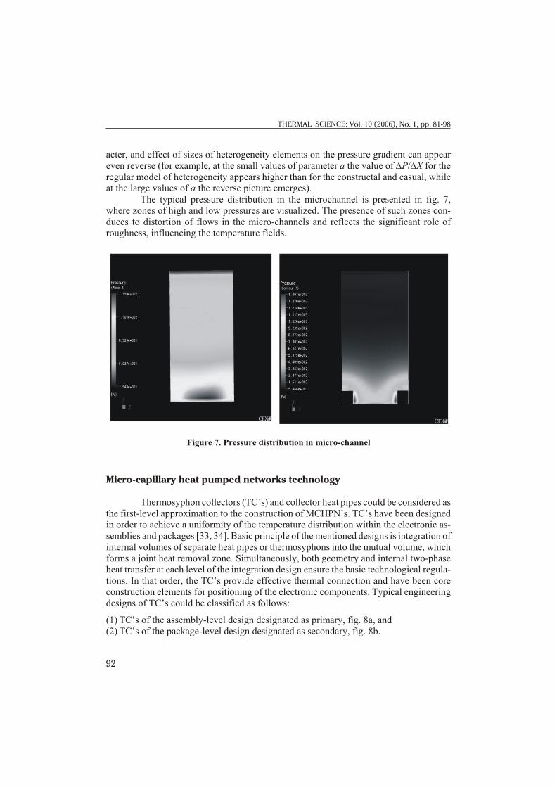
The typ i cal pres sure dis tri bu tion in the microchannel is pre sented in fig. 7,where zones of high and low pres sures are vi su al ized. The pres ence of such zones con -duces to dis tor tion of flows in the mi cro-chan nels and re flects the sig nif i cant role ofrough ness, in flu enc ing the tem per a ture fields.
Micro-capillary heat pumped networks technology
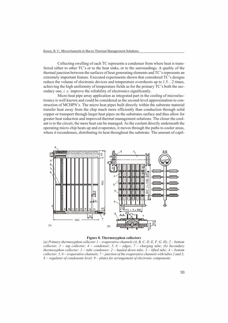
Thermosyphon col lec tors (TC’s) and col lec tor heat pipes could be con sid ered as the first-level ap prox i ma tion to the con struc tion of MCHPN’s. TC’s have been de signedin or der to achieve a uni for mity of the tem per a ture dis tri bu tion within the elec tronic as -sem blies and pack ages [33, 34]. Ba sic prin ci ple of the men tioned de signs is in te gra tion of in ter nal vol umes of sep a rate heat pipes or thermosyphons into the mu tual vol ume, whichforms a joint heat re moval zone. Si mul ta neously, both ge om e try and in ter nal two-phaseheat trans fer at each level of the in te gra tion de sign en sure the ba sic tech no log i cal reg u la -tions. In that or der, the TC’s pro vide ef fec tive ther mal con nec tion and have been corecon struc tion el e ments for po si tion ing of the elec tronic com po nents. Typ i cal en gi neer ingde signs of TC’s could be clas si fied as fol lows:
(1) TC’s of the assembly-level design designated as primary, fig. 8a, and(2) TC’s of the package-level design designated as secondary, fig. 8b.
92
THERMAL SCIENCE: Vol. 10 (2006), No. 1, pp. 81-98
Figure 7. Pressure distribution in micro-channel
Col lect ing swell ing of each TC rep re sents a con denser from where heat is trans -ferred ei ther to other TC’s or to the heat sinks, or to the sur round ings. A qual ity of thether mal junc tion be tween the sur faces of heat gen er at ing el e ments and TC’s rep re sents an ex tremely im por tant fea ture. Ex e cuted ex per i ments shown that con sid ered TC’s de signsre duce the vol ume of elec tronic de vices and tem per a ture over shoots up to 1.5…2 times,achiev ing the high uni for mity of tem per a ture fields as for the pri mary TC’s both the sec -ond ary one, i. e. im prove the re li abil ity of elec tron ics sig nif i cantly.
Mi cro heat pipe ar ray ap pli ca tion as in te grated part in the cool ing of mi cro elec -tron ics is well known and could be con sid ered as the sec ond-level ap prox i ma tion to con -struc tion of MCHPN’s. The mi cro heat pipes built di rectly within the sub strate ma te rialtrans fer heat away from the chip much more ef fi ciently than con duc tion through solidcop per or trans port through larger heat pipes on the sub strates sur face and thus al low forgreater heat re duc tion and im proved ther mal man age ment so lu tions. The closer the cool -ant is to the cir cuit, the more heat can be man aged. As the cool ant di rectly un der neath theop er at ing mi cro chip heats up and evap o rates, it moves through the paths to cooler ar eas,where it recondenses, dis trib ut ing its heat through out the sub strate. The amount of cap il -
93
Kosoy, B. V.: Microchannels in Macro Thermal Management Solutions
Figure 8. Thermosyphon collectors(a) Primary thermosyphon collector 1 - evaporative channels (A, B, C, D, E, F, G, H); 2 - bottomcollector; 3 - top collector; 4 - condenser; 5, 6 - edges; 7 - charging tube; (b) Secondarythermosyphon collector: 1 - tube condenser; 2 - hauled down tube; 3 - lifted tube; 4 - bottomcollector; 5, 6 - evaporative channels; 7 - junction of the evaporative channels with tubes 2 and 3;8 - regulator of condensate level; 9 - plates for arrangement of electronic components
lary pres sure in side the tubes is a func tion of the size of the pas sages. As the struc tures get smaller, more pump ing ac tion is cre ated within the sub strate. A cool ant and mi cro pipege om e try can be se lected that best trans fers heat given each de vice’s de sign and op er at -ing tem per a ture range.
Mallik et al. [35] de vel oped a tran sient three-di men sional fi nite dif fer encemodel to eval u ate the per cent re duc tion in the max i mum chip sur face tem per a ture, themean sur face tem per a ture, and the ther mal gra di ent oc cur ring on the chip for 100 mm di -am e ter pipes. They ob served sig nif i cant re duc tions in the max i mum chip tem per a ture ofup to 40 per cent and in the tran sient re sponse time, point ing up the im prove ment of theheat re mov ing ca pa bil ity. Pe ter son et al. [36] per formed ex per i ments on mi cro heat pipear ray. Their re sults proved clearly that an ar ray of mi cro heat pipes as an in te gral part ofsil i con wa fers can sig nif i cantly im prove the per for mance and re li abil ity of semi con duc -tor de vices, by in creas ing the ef fec tive ther mal con duc tiv ity, de creas ing ther mal gra di -ents, and re duc ing the in ten sity and num ber of lo cal ized hot spots.
As it was men tioned, fur ther im prove ments in ther mal de sign and op ti mi za tionof mi cro heat pipe ar rays for cool ing of elec tron ics should be ac com plished by means ofthe constructal prin ci ple of shape and struc ture for ma tion. Keep ing in mind theconstructal prin ci ple and wick pump ing tech nol ogy tools, a next step to MCHPN’s de -sign could be de vel oped by us ing the novel so lu tions from microengineering andnanotechnology (see fig. 9).
Concluding remarks
Con ven tional cool ing tech nol o gies in the elec tronic in dus try have lim i ta tions on re mov ing non-uni form, high heat fluxes from the sur face of mi cro pro ces sors. The com bi -
94
THERMAL SCIENCE: Vol. 10 (2006), No. 1, pp. 81-98
Figure 9. New generation of micro-capillary heat pumping networks
na tion of high heat fluxes with the non-uni for mity of heat dis si pa tion re quires tech nol o -gies able to re move large amounts of heat in a spa tially and tem po rally vari able man ner.
Ther mal man age ment sys tem for ad vanced elec tron ics needs to meet the se lec -tion cri te rion of re li abil ity, sim plic ity, low cost, and above all, ef fec tive ness. Ac count inga huge num ber of mi cro com po nents with vary heat gen er a tion in ten si ties and con -tradictory tem per a ture re gimes within a com plex elec tronic sys tem, ther mo dy nam i callyproved, op ti mum ther mal man age ment sys tem ap pears a com plex net work of cool ing,heat dis si pat ing, trans fer and pump ing el e ments. Dif fer ent ideas have been used to de -velop such high per for mance ther mal man age ment sys tems. Re search ers try to uti lize thepas sive forces in the liq uid such as cap il lary ef fect, os motic ef fect, vis cos ity ef fect, andex pan sion ef fect to cre ate self cir cu lat ing cool ing and heat dis si pat ing de vices.
Since Cot ter [37] pro posed us ing mi cro heat pipes for heat re moval in semi con -duc tor ma te ri als, a num ber of steady state and tran sient mod els for mi cro heat pipes havebeen pro posed, tested and ver i fied. Mi cro heat pipes have po ten tial to solve the over heat -ing prob lem at submicron level. Fur ther im prove ments in ther mal de sign and op ti mi za -tion of mi cro heat pipe ar rays for cool ing of elec tron ics should be ac com plished by means of the constructal prin ci ple of shape and struc ture for ma tion.
Ve loc ity, pres sure and tem per a ture fields oc cur ring in mi cro- and macro-chan-nels at the anal y sis of dif fer ent mod els of het er o ge neous sur faces (reg u lar, ca sual, andconstructal) con firm the sim i lar ity of im pulse trans fer pro cesses at iden ti cal bound arycon di tions. Thus, con ven tional cor re la tions for the heat trans fer co ef fi cients and hy drau -lic resistances at the flows in chan nels re main ap pli ca ble for mi cro- and macro-chan nelscase, if bound ary con di tions and geo met ri cal lim i ta tions are prop erly for mu lated. Ex ist -ing di ver gences in ex per i men tal data of dif fer ent au thors are con nected with dif fi cul tiesin re pro duc tion of iden ti cal ex per i men tal con di tions and their ac cu racy, in stead of newphys i cal phe nom ena that could be re lated to the mi cro-scales, and the re cent ex per i men -tal data just con firmed such stand point [38].
It is clear that the fol low ing prog ress in mi cro elec tron ics should be as so ci atedwith the in te gra tion of mi cro-cool ing, heat pump ing, mi cro-chan nels and other mi cro-de -vices into the en tire elec tronic sys tem. Nat u rally, en gi neer ing ther mo dy nam ics’ state ofthe art with re spect to the de sign and op ti mi za tion of cool ing, re frig er a tion and heatpump ing sys tems both with me chan i cal and non-me chan i cal com pres sion prin ci ples willrep re sent a sig nif i cant knowl edge-base for the novel MCHPN’s de vel op ments. Prob a blythe next gen er a tion of the MCHPN’s will rep re sent a com plete anal ogy to abiotic skin formi cro-elec tronic de vice. Thus, us ing of cap il lary-po rous struc tures as the con struc tion el -e ment and two-phase liq uid-va por tran si tion as the es sen tial heat trans fer mech a nism will per form a re al is tic op por tu nity for the ef fec tive net work in te gra tion in the near est de -cades.
Nomenclature
A – flow area , [m2]A12 - solid/fluid surface area, [m2]
95
Kosoy, B. V.: Microchannels in Macro Thermal Management Solutions
a - width of the channel, [mm]b, c - distances between the elements of roughness through the length and breadth of
jjjjstream, [mm]C, m, n - constants, [–]f - loss coefficient, [–] H - height of the channel, [mm]h - height of the element of heterogeneity, [mm] kp - thermal conductivity, [Wm–1K–1)]Nu - Nusselt number, [–]Dp - pressure drop, [Pa]Q - volumetric flow rate, [m3/s]Pr - Prandtl number, [–]Re - Reynolds number, [–]Um - average velocity of liquid flow in the minimum cross section of the channel, [m/s]UX, UY, UZ - dimensionless components of flow velocity along side the coordinate axes, rated to
– Um, [–]V - nominal solid space, [m3]Vp - void space, [m3]X, Y, Z - dimensionless coordinates, rated to H, [–]
[1] Park, K. A., Bergles, A. E., Boil ing Heat Trans fer Char ac ter is tics of Sim u lated Mi cro elec -tronic Chips with De tach able Heat Sinks, Pro ceed ings, 8th In ter na tional Heat Trans fer Con -fer ence, San Fransisco, USA, 1986, Vol. 4, pp. 2099-2104
[2] Carvalho, R. D. M., Bergles, A. E., The In flu ence of Subcooling on the Pool Nu cle ate Boil ing and Crit i cal Heat Flux of Sim u lated Elec tronic Chips, Pro ceed ings, 9th In ter na tional HeatTrans fer Con fer ence, Je ru sa lem, Is rael, 1990, pp. 289-294
[3] Bergles, A. E., Bar-Co hen, A., Di rect Liq uid Cool ing of Mi cro elec tronic Com po nents, in:Ad vances in Ther mal Mod el ing of Elec tronic Com po nents and Sys tems (Eds. A. Bar-Co hen,A. D. Kraus), Hemi sphere Pub lish ing Corp. New York, USA, 1990, Vol. 2, pp. 233-250
[4] Incropera, F. P., Liq uid Im mer sion Cool ing of Elec tronic Com po nents, Heat Trans fer inElec tronic and Mi cro elec tronic Equip ment (Ed. A. E. Bergles), Hemi sphere Pub lish ingCorp., New York, USA, 1990, pp. 407-444
[5] Bar-Co hen, A., Ther mal Man age ment of Elec tronic Com po nents with Di elec tric Liq uids, In -ter na tional Jour nal of JSME, 36 (1993), 1, pp. 1-25
[6] Ma, C. F., Gan, Y. P., Tian, Y. C., Lei, D. H., Gomi, T., Liq uid Jet Im pinge ment Heat Trans -fer with or with out Boil ing, Jour nal of Ther mal Sci ence, 2 (1993), 1, pp. 32-49
[7] Ravigururajan, T. S., Bergles, A. E., Vi su al iza tion of Flow Phe nom ena Near En hanced Sur -faces, Jour nal of Heat Trans fer, 116 (1994), 1, pp. 54-57
[8] Webb, R. L., Prin ci ples of En hanced Heat Trans fer, John Wiley & Sons, New York, USA,1994
96
THERMAL SCIENCE: Vol. 10 (2006), No. 1, pp. 81-98
[9] Nakayama, W., Daikoku, T., Kuwahara, H., Nakajima, T., Dy namic Model of En hance ment Boil ing Heat Trans fer on Po rous Sur faces, Part I: Ex per i men tal In ves ti ga tion, ASME Jour nalof Heat Trans fer, 102 (1980), 3, pp. 445-450
[10] Amon, C. H., Murthy, J. Y., Yao, S. C., Narumanchi, S., Wu, C. F., Hsieh, C. C., MEMS En -abled Ther mal Man age ment of High-Heat-Flux De vices, Ed i fice: Em bed ded Drop let Im -pinge ment for In te grated Cool ing of Elec tron ics, Jour nal of Ex per i men tal Ther mal andFluid Sci ence, 25 (2001), 5, pp. 231-242
[11] Pe ter son, G. P., An In tro duc tion to Heat Pipes, John Wiley & Sons, Inc., New York, USA,1994
[12] Kosoy, B. V., Wick Pump ing Tech nol ogy, Pro ceed ings, NATO ASI on Emerg ing Tech nol o -gies and Tech niques in Po rous Me dia, Ovidius Uni ver sity Press, Constantza, Ro ma nia, 2003,pp. 198-208
[13] Kaviany, M., Prin ci ples of Heat Trans fer in Po rous Me dia, 2nd ed, Springer-Verlag, Berlin,1999
[14] Kosoy, B. V., The Fea si bil ity and De sign of High Pres sure Wick Evap o ra tors for Re frig er a -tion Ma chines, Pro ceed ings on CD, In ter na tional Con gress of Re frig er a tion, Wash ing tonDC, 2003, ICR-204
[15] Kosoy, B. V., Ther mo dy namic Con cept of Cap il lary Pumped Re frig er a tion Loop, Pro ceed -ings, 5th International Sem i nar Heat Pipes, Heat Pumps, Re frig er a tors, Minsk, 2003, pp.320-328
[16] Kosoy, B.V., Pas sive Ther mal Con trol in Re frig er a tion and Cool ing, Pro ceed ings, In ter na -tional Short Course on Pas sive Ther mal Con trol, Antalya, Tur key, Beggel House, New York,USA, 2003, pp. 131-149
[17] Shoji, S., Esashi, M., Matsuo, M., Pro to type Min ia ture Blood Gas An a lyzer Fab ri cated on aSil i con Wa fer, Sen sors Ac tu a tors, 14 (1988), 1, pp. 101–107
[18] Gravesen, P., Branebjerg, J., Jensen, O. S., Microfluidics, J. Micromech. Microeng., 3(1993), 1, pp. 168–182
[19] Takagi, H. et al., Phase Trans for ma tion Type Mi cro Pump, Pro ceed ings, In ter na tional Sym -po sium on Mi cro Ma chine and Hu man Sci ence, Nagoya, Ja pan, 1994, pp. 199-202
[20] Ozaki, K., Pump ing Mech a nism Us ing Pe ri odic Phase Changes of a Fluid, Pro ceed ings,IEEE Mi cro Elec tro Me chan i cal Sys tems Work shop, 1995, pp. 31-36
[21] Kobayashi, Y., Heat Pipe Ther mo dy namic Cy cle and Its Ap pli ca tions, ASME Jour nal of So -lar En ergy En gi neer ing, 107 (1985), 1, pp. 153-159
[22] John son, P. et al., Heat Pipe Tur bine Be com ing a Re al ity, Pro ceed ings, 5th IHPS, Tsukuba,Ja pan, 1996, pp. 338-343
[23] Scharff, P., New Car bon Ma te ri als for Re search and Tech nol ogy, Car bon, 36 (1998), 4, pp.481-486
[24] Co hen, M. L., Pre dict ing New Ma te ri als and Their Prop er ties, Solid Sate Com mu ni ca tions,107 (1998), pp. 589-596
[25] Hall, M., Wick Sur face Mod el ing in Heat Pipes, Trans ac tions,1991 Amer i can Nu clear So ci -ety Win ter Meet ing, San Francisco, USA, 1991, p. 735
[26] Ellison, G. N., Ther mal Com pu ta tions for Elec tronic Equip ment, Rob ert E. Krieger Pub lish -ing Co., Malibar, FL, USA, 1989
[27] Belady, C., Kelkar, K. M., Patankar, S. V., Im proved Pro duc tiv ity with Use of Flow Net workMod el ing in Elec tron ics Pack ag ing, Elec tron ics Cool ing, 5 (1999), 1, pp. 36-40
[28] Bejan, A., Constructal-The ory Net work of Con duct ing Paths for Cool ing a Heat Gen er at ing Vol ume, Int. J. Heat Mass Trans fer, 40 (1997), 3, pp. 799-816
[29] Bejan, A., Ad vanced En gi neer ing Ther mo dy nam ics, 2nd ed, John Wiley and Sons, New York, USA, 1997
[30] Bejan, A. et al., Po rous and Com plex Flow Struc tures in Mod ern Tech nol o gies, Springer-Verlag, Berlin, 2004
[31] Kakac, S., Microscale Heat Trans fer – Fun da men tals and Ap pli ca tions in Bi o log i cal andMicroelectromechanical Sys tems, Ex tended Ab stracts, NATO ASI, Cesme, Tur key, 2004
97
Kosoy, B. V.: Microchannels in Macro Thermal Management Solutions
[32] Patankar, S. V., Liu, C. H., Spar row, E. M., Fully De vel oped Flow and Heat Trans fer in Ducts Hav ing Streamwise-Pe ri odic Vari a tions of Cross Sec tional Area, ASME J. Heat Trans fer, 99 (1997), 1, pp. 180-186
[33] Smirnov, H. F., Reznikov, V. V., Thermophysical Prob lems of Elec tronic Equip ment Cool -ing with the Re frig er at ing Evap o ra tive Sys tems, Pro ceed ings, Sem i nar on Heat and MassTrans fer in the Elec tronic De vice Tech nol o gies, Minsk, 1989, Vol. 1, pp. 10-22
[34] Smirnov, H. F., Kosoy, B. V., Tkachenko, V. B., Heat pipe tech nol ogy for Re frig er a tion andCool ing, Key note lec ture #1, Pro ceed ings, 12th In ter na tional Heat Pipe Con fer ence, Mos cow, 2002, pp. 5-17
[35] Mallik, A. K., Pe ter son, G. P., Weichold, M. H., On the Use of Mi cro Heat Pipes as an In te -gral Part of Semi con duc tor De vices, Jour nal of Elec tronic Pack ag ing, 114 (1992), 4, pp.436-442
[36] Pe ter son, G. P., Duncan, A. B., Weichold, M. H., Ex per i men tal In ves ti ga tions of Mi cro HeatPipes Fab ri cated in Sil i con Wa fers, Jour nal of Heat Trans fer, 115 (1993), 3, pp. 751-756
[37] Cot ter, T. P., Prin ci ples and Pros pects for Mi cro Heat Pipes, Pro ceed ings, 5th In ter na tionalHeat Pipe Con fer ence, Tsukuba, Ja pan, 1984, pp. 328-335
[38] Agoustini, B. et al., Liq uid Flow Fric tion Fac tor and Heat Trans fer Co ef fi cient in SmallChan nels: an Ex per i men tal In ves ti ga tion, Ex per i men tal Ther mal and Fluid Sci ence, 28(2004), 2, pp. 97-103
Author's address:
B. V. KosoyOdessa State Academy of Refrigeration,1/3, Dvoryanskaya St.65082 OdessaUkraine