6
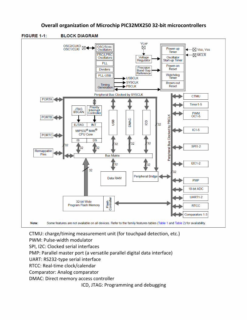
Overall organization of Microchip PIC32MX250 32‐bit microcontrollers
CTMU: charge/timing measurement unit (for touchpad detection, etc.) PWM: Pulse‐width modulator SPI, I2C: Clocked serial interfaces PMP: Parallel master port (a versatile parallel digital data interface) UART: RS232‐type serial interface RTCC: Real‐time clock/calendar Comparator: Analog comparator DMAC: Direct memory access controller
ICD, JTAG: Programming and debugging

Organization of I/O pins
Pins can be used as digital input, digital output, or analog input; when used as outputs they can be configured normally or in open‐drain configuration. As inputs, they include optional pullup resistors. Finally, peripheral devices like UARTs and counters can be flexibly assigned to varying pins.

Example of an internal peripheral controller: USB interface unit

Programming
The program memory is written with a special high‐voltage programming pulse,
generated by a PICkit3 programmer or similar device. The processors have a register and
stack structure optimized for programming in C or C++. The actual hardware instruction
set consists of primitive operations like the following:
Most instructions will operate on 32‐bit registers in a single instruction cycle; i.e., at a rate
of 40‐50 MHz. This is equivalent to a microprocessor with a much higher clock speed,
since a complete instruction executes on each cycle.

Typical circuit
The schematic diagram below shows a PIC32 microcontroller with a precise crystal clock,
a 6‐pin programming header, a serial display output, and an SPI interface to a dual 12‐bit
DAC. It is similar to the configuration used in Lab 10 for Physics 3150.


