1 Environment, Energy Security, and Sustainability (E2S2) Symposium and Exhibition Microgrid with Solar Power and Fuel Cell Technology 16 June 2010 Dan Markiewicz Senior Director, Electrical Design
Transcript
1
Environment, Energy Security, and Sustainability (E2S2)
Symposium and Exhibition
Microgrid with Solar Power and Fuel Cell Technology
16 June 2010
Dan MarkiewiczSenior Director, Electrical Design
Report Documentation Page Form ApprovedOMB No. 0704-0188
Public reporting burden for the collection of information is estimated to average 1 hour per response, including the time for reviewing instructions, searching existing data sources, gathering andmaintaining the data needed, and completing and reviewing the collection of information. Send comments regarding this burden estimate or any other aspect of this collection of information,including suggestions for reducing this burden, to Washington Headquarters Services, Directorate for Information Operations and Reports, 1215 Jefferson Davis Highway, Suite 1204, ArlingtonVA 22202-4302. Respondents should be aware that notwithstanding any other provision of law, no person shall be subject to a penalty for failing to comply with a collection of information if itdoes not display a currently valid OMB control number.
1. REPORT DATE 16 JUN 2010 2. REPORT TYPE
3. DATES COVERED 00-00-2010 to 00-00-2010
4. TITLE AND SUBTITLE Microgrid with Solar Power and Fuel Cell Technology
9. SPONSORING/MONITORING AGENCY NAME(S) AND ADDRESS(ES) 10. SPONSOR/MONITOR’S ACRONYM(S)
11. SPONSOR/MONITOR’S REPORT NUMBER(S)
12. DISTRIBUTION/AVAILABILITY STATEMENT Approved for public release; distribution unlimited
13. SUPPLEMENTARY NOTES Presented at the NDIA Environment, Energy Security & Sustainability (E2S2) Symposium & Exhibitionheld 14-17 June 2010 in Denver, CO. U.S. Government or Federal Rights License
14. ABSTRACT
15. SUBJECT TERMS
16. SECURITY CLASSIFICATION OF: 17. LIMITATION OF ABSTRACT Same as
Report (SAR)
18. NUMBEROF PAGES
21
19a. NAME OFRESPONSIBLE PERSON
a. REPORT unclassified
b. ABSTRACT unclassified
c. THIS PAGE unclassified
Standard Form 298 (Rev. 8-98) Prescribed by ANSI Std Z39-18
2
OVERVIEW
• Background
• Terminology
• Project Objective
• Requirements
• Microgrid System
• Planned Testing
3
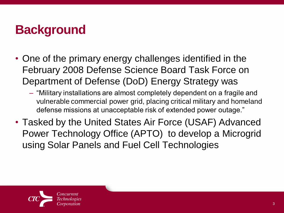
Background
• One of the primary energy challenges identified in the
February 2008 Defense Science Board Task Force on
Department of Defense (DoD) Energy Strategy was – “Military installations are almost completely dependent on a fragile and
vulnerable commercial power grid, placing critical military and homeland
defense missions at unacceptable risk of extended power outage.”
• Tasked by the United States Air Force (USAF) Advanced
Power Technology Office (APTO) to develop a Microgrid
using Solar Panels and Fuel Cell Technologies
4
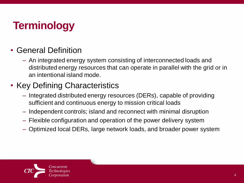
Terminology
• General Definition– An integrated energy system consisting of interconnected loads and
distributed energy resources that can operate in parallel with the grid or in
an intentional island mode.
• Key Defining Characteristics– Integrated distributed energy resources (DERs), capable of providing
sufficient and continuous energy to mission critical loads
– Independent controls; island and reconnect with minimal disruption
– Flexible configuration and operation of the power delivery system
– Optimized local DERs, large network loads, and broader power system
5
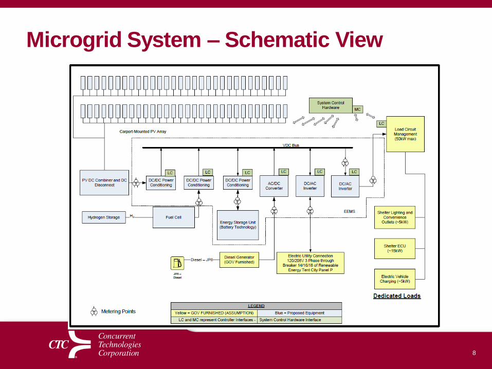
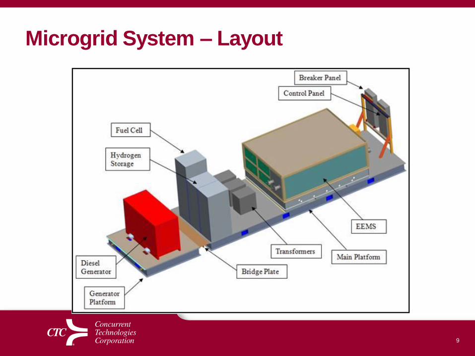
Project Objective
• Design, integrate, test and sustain a DC based 50 kW
microgrid with multiple power sources which will
demonstrate:
– Reliably supply power to dedicated loads in a prioritized fashion
– Supply excess power to the grid, when appropriate
– Make intelligent decisions when the PV array (and other sources)
should directly supply power to the load
– Make intelligent decisions when the PV array (and other sources)
should supply power to charge the battery energy storage system
– Make intelligent decisions when none of the options are available
and allow the load to be sourced via a grid connection or the
government furnished back-up generator.
6
Requirements
• Ability to run grid tied or islanded
• High reliability electrical supply to identified loads
• Load prioritization
• Effectively manage energy storage to maximize energy
supply to critical loads
• Control system to monitor loads and sources, and
effectively manage these loads and sources to attain high
reliability supply to critical loads
• Data collection to determine metrics of system operation
• Supply a maximum of 50 kW output
7
Requirements - Site
• Environmental and weather concerns– Lightning protection
• Stand-off distances from tents and specific equipment
• Footprint, size, and overall weight of equipment
• Ability to cover, conceal, and protect interconnecting