Microphone Intermodulation Distortion Measurements using the High Pressure Microphone Calibrator Type 4221 by Pierre Bernard, Bruel & Kjasr IntTOdurtion since, with the 4221, sound pres- sure is independent of coupler vo- In applications where micro- lume variation, atmospheric pres- phones are used to measure very sure variation, change from adia- high sound pressure levels, special batic to isothermic conditions at low calibration may be needed to check frequencies, non linearity in load im- linearity, distortion and other char- pedance at high dynamic pressures. acteristics of the measuring system. Further, harmonic distortion of Type For measuring intermodulation dis- 4221 is approx. 6dB lower than tortion, both excitation frequencies the theoretical limit obtainable with should be regulated. A system al- a constant volume displacement sys- lowing this type of measurement at tern at 164dB. Full details on Type sound pressure levels up to 164dB 4221 are given in References [1] is described in the following and ty- and [2]. pical results are given. For intermodulation distortion, measurements, two excitation tones MPBSUrinQ SvStfim are necessar V- Botn tones should ** be regulated independently due to In order to obtain very high sound the resonance of the coupler pressure levels, the B & K High Pres- (Fig.2). Using traditional compres- sure Microphone Calibrator Type sion techniques, such a dual fre- 4221 should be used. This instru- quency compressor loop would re- ment, shown in Fig. 1, allows meas- suit in a relatively complex system urements at sound pressure levels (Reference [3]). However, a rather up to 164dB with continuous exci- simple measurement system can be tation (levels up to 172dB SPL may obtained using the Audio Test Sta- be obtained with tone-burst excita- tion Type 21 1 6 (Fig.3). tinn iicinn thp fnPtinn 5-wsfpm Tvne tion using the Gating System Type 4440). The Calibrator is delivered with two couplers, a Low Frequency Cou- pler allowing measurements down to below 0,01 Hz, and a High Pres- sure Coupler giving a frequency range of 3 Hz to 1000 Hz (using compression to compensate for the coupler resonance). The high sound pressure is produced by a piston moved by an electrodynamic exci- ter. Such a force-controlled system has definite advantages over con- stant volume displacement systems (such as the pistonphone) for very high sound pressure level excitation 083—80 Fig.2. Frequency Response of Type 4221 fitted with the High Pressure Coupler Fig.1. The High Pressure Microphone Cali- brator Type 4221
Transcript
Microphone Intermodulation Distortion Measurements using the High Pressure Microphone Calibrator Type 4221
by Pierre Bernard, Bruel & Kjasr
IntTOdurtion since, wi th the 4 2 2 1 , sound pressure is independent of coupler vo-
In applications where micro- lume variation, atmospheric pres-phones are used to measure very sure variation, change from adia-high sound pressure levels, special batic to isothermic conditions at low calibration may be needed to check frequencies, non linearity in load im-linearity, distortion and other char- pedance at high dynamic pressures. acteristics of the measuring system. Further, harmonic distortion of Type For measuring intermodulation dis- 4221 is approx. 6dB lower than tort ion, both excitation frequencies the theoretical limit obtainable with should be regulated. A system al- a constant volume displacement sys-lowing this type of measurement at tern at 164dB. Full details on Type sound pressure levels up to 164dB 4221 are given in References [1] is described in the following and ty- and [2]. pical results are given.
For intermodulation distort ion, measurements, two excitation tones
MPBSUrinQ SvStfim a r e n e c e s s a r V - B o t n tones should ** be regulated independently due to
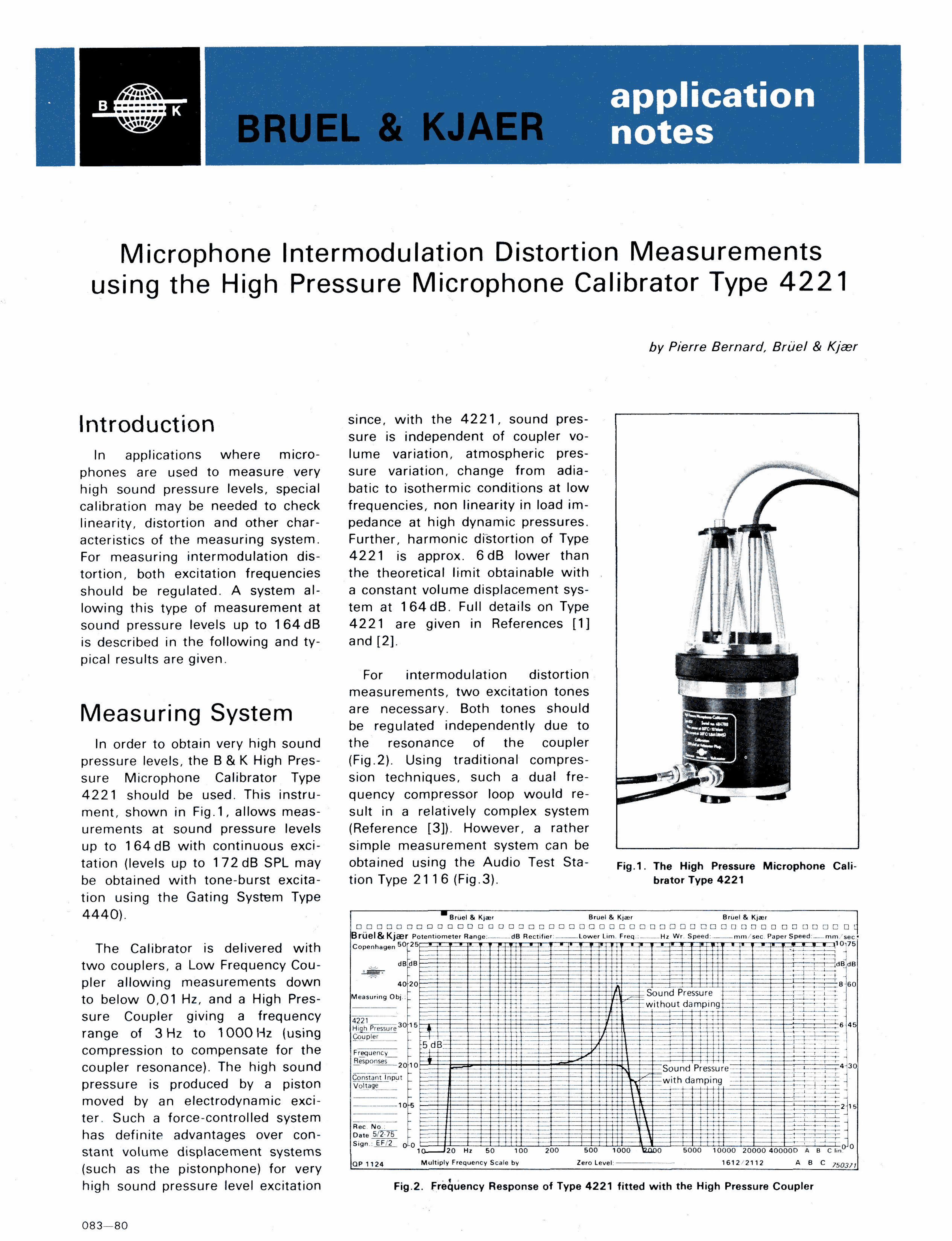
In order to obtain very high sound the resonance of the coupler pressure levels, the B & K High Pres- (Fig.2). Using traditional compres-sure Microphone Calibrator Type sion techniques, such a dual fre-4221 should be used. This instru- quency compressor loop would re-ment, shown in Fig. 1 , allows meas- suit in a relatively complex system urements at sound pressure levels (Reference [3]). However, a rather up to 164dB with continuous exci- simple measurement system can be tation (levels up to 172dB SPL may obtained using the Audio Test Sta-be obtained wi th tone-burst excita- tion Type 21 1 6 (Fig.3). tinn iicinn thp fnPtinn 5-wsfpm Tvne tion using the Gating System Type 4440) .
The Calibrator is delivered wi th two couplers, a Low Frequency Coupler allowing measurements down to below 0,01 Hz, and a High Pressure Coupler giving a frequency range of 3 Hz to 1000 Hz (using compression to compensate for the coupler resonance). The high sound pressure is produced by a piston moved by an electrodynamic exciter. Such a force-controlled system has definite advantages over constant volume displacement systems (such as the pistonphone) for very high sound pressure level excitation
083—80
Fig.2. Frequency Response of Type 4221 f i t ted with the High Pressure Coupler
F ig .1 . The High Pressure Microphone Calibrator Type 4221
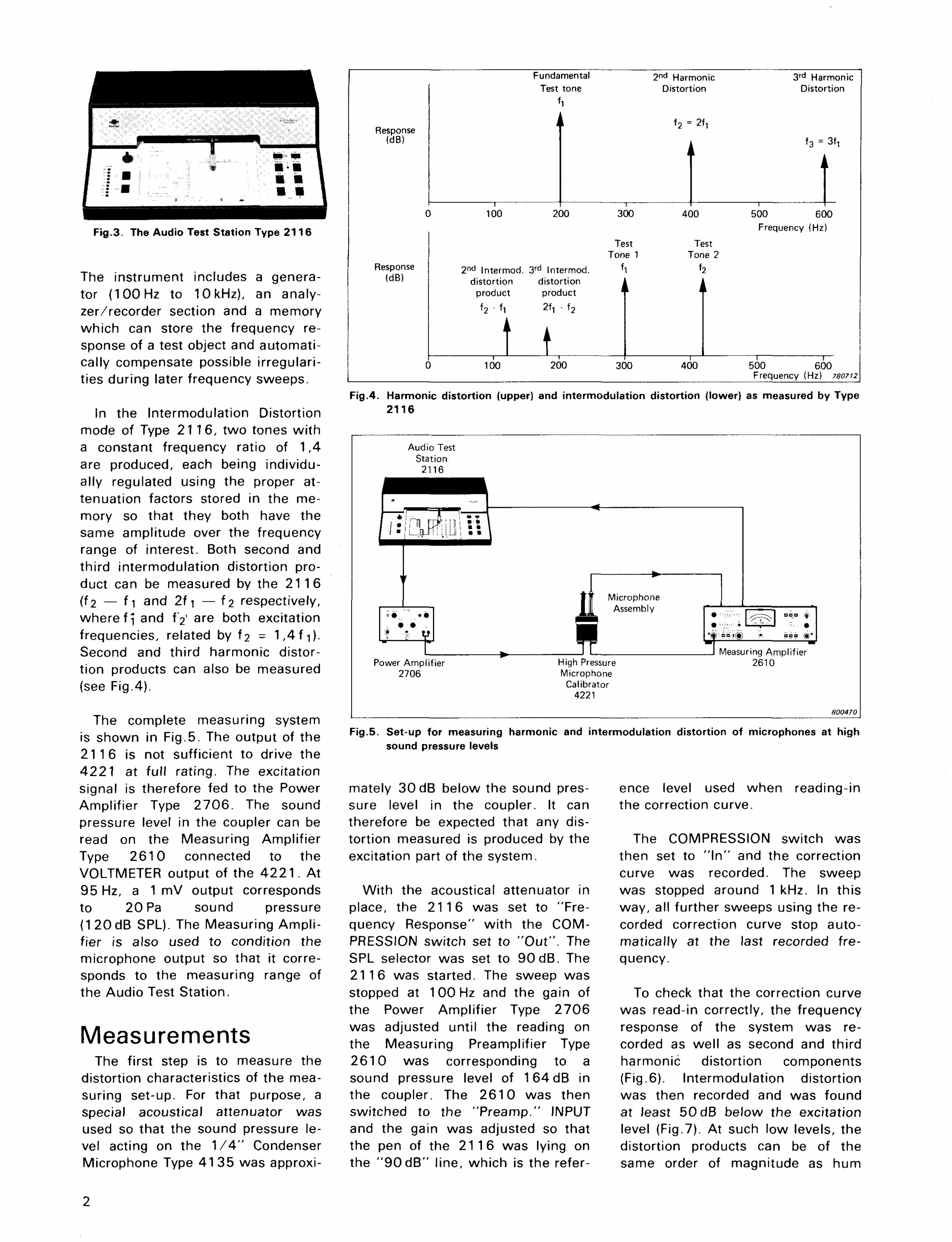
Fig.5. Set-up for measuring harmonic and intermodulation distortion of microphones at high sound pressure levels
mately 30 dB below the sound pres- ence level used when reading-in sure level in the coupler. It can the correction curve. therefore be expected that any distortion measured is produced by the The COMPRESSION switch was excitation part of the system. then set to " I n " and the correction
curve was recorded. The sweep With the acoustical attenuator in was stopped around 1 kHz. In this
place, the 2116 was set to "Fre- way, all further sweeps using the re-quency Response" wi th the COM- corded correction curve stop auto-PRESSION switch set to "Out" . The matically at the last recorded fre-SPL selector was set to 90dB . The quency. 2116 was started. The sweep was stopped at 1 00 Hz and the gain of To check that the correction curve the Power Amplifier Type 2706 was read-in correctly, the frequency was adjusted until the reading on response of the system was re-the Measuring Preamplifier Type corded as well as second and third 2610 was corresponding to a harmonic distortion components sound pressure level of 164dB in (Fig.6). Intermodulation distortion the coupler. The 2610 was then was then recorded and was found switched to the "Preamp." INPUT at least 50 dB below the excitation and the gain was adjusted so that level (Fig.7). At such low levels, the the pen of the 2116 was lying on distortion products can be of the the " 9 0 d B " line, which is the refer- same order of magnitude as hum
Fig.4. Harmonic distortion (upper) and intermodulation distortion (lower) as measured by Type 2 1 1 6
Fig.3. The Audio Test Station Type 2 1 1 6
The instrument includes a generator (100 Hz to 10 kHz), an analyzer/recorder section and a memory which can store the frequency response of a test object and automatically compensate possible irregularities during later frequency sweeps.
In the Intermodulation Distortion mode of Type 2116 , two tones wi th a constant frequency ratio of 1,4 are produced, each being individually regulated using the proper attenuation factors stored in the memory so that they both have the same amplitude over the frequency range of interest. Both second and third intermodulation distortion product can be measured by the 2116 (f2 — f i and 2f i — f2 respectively, where f i and f'2' are both excitation frequencies, related by f2 - 1 ,4 f i ) . Second and third harmonic distortion products can also be measured (see Fig.4).
The complete measuring system is shown in Fig.5. The output of the 2116 is not sufficient to drive the 4221 at full rating. The excitation signal is therefore fed to the Power Amplifier Type 2706 . The sound pressure level in the coupler can be read on the Measuring Amplifier Type 2610 connected to the VOLTMETER output of the 4 2 2 1 . At 95 Hz, a 1 mV output corresponds to 20 Pa sound pressure (1 20 dB SPL). The Measuring Amplifier is also used to condition the microphone output so that it corresponds to the measuring range of the Audio Test Station.
Measurements The first step is to measure the
distortion characteristics of the measuring set-up. For that purpose, a special acoustical attenuator was used so that the sound pressure level acting on the 1 / 4 " Condenser Microphone Type 41 35 was approxi-
2
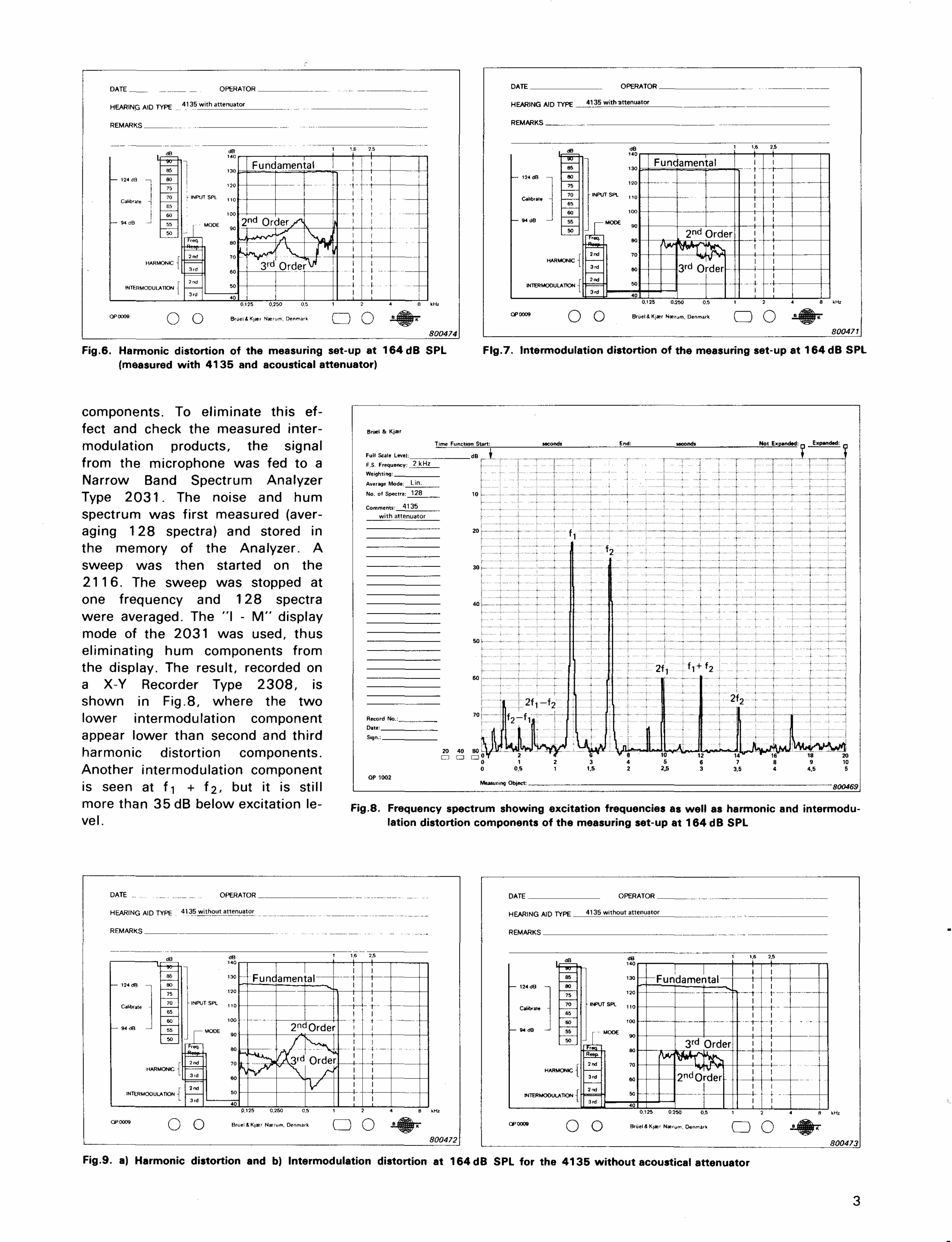
Fig.9. a) Harmonic distortion and b) Intermodulation distortion at 164dB SPL for the 4135 without acoustical attenuator
3
Fig.8. Frequency spectrum showing excitation frequencies as well as harmonic and intermodulation distortion components of the measuring set-up at 164 dB SPL
Fig.6. Harmonic distortion of the measuring set-up at 164dB SPL Fig.7. Intermodulation distortion of the measuring set-up at 164dB SPL (measured with 4135 and acoustical attenuator)
components. To eliminate this effect and check the measured intermodulation products, the signal from the microphone was fed to a Narrow Band Spectrum Analyzer Type 2 0 3 1 . The noise and hum spectrum was first measured (averaging 128 spectra) and stored in the memory of the Analyzer. A sweep was then started on the 2116. The sweep was stopped at one frequency and 128 spectra were averaged. The "I - M " display mode of the 2031 was used, thus eliminating hum components from the display. The result, recorded on a X-Y Recorder Type 2308, is shown in Fig.8, where the two lower intermodulation component appear lower than second and third harmonic distortion components. Another intermodulation component is seen at f i + f2 , but it is still more than 35 dB below excitation level.
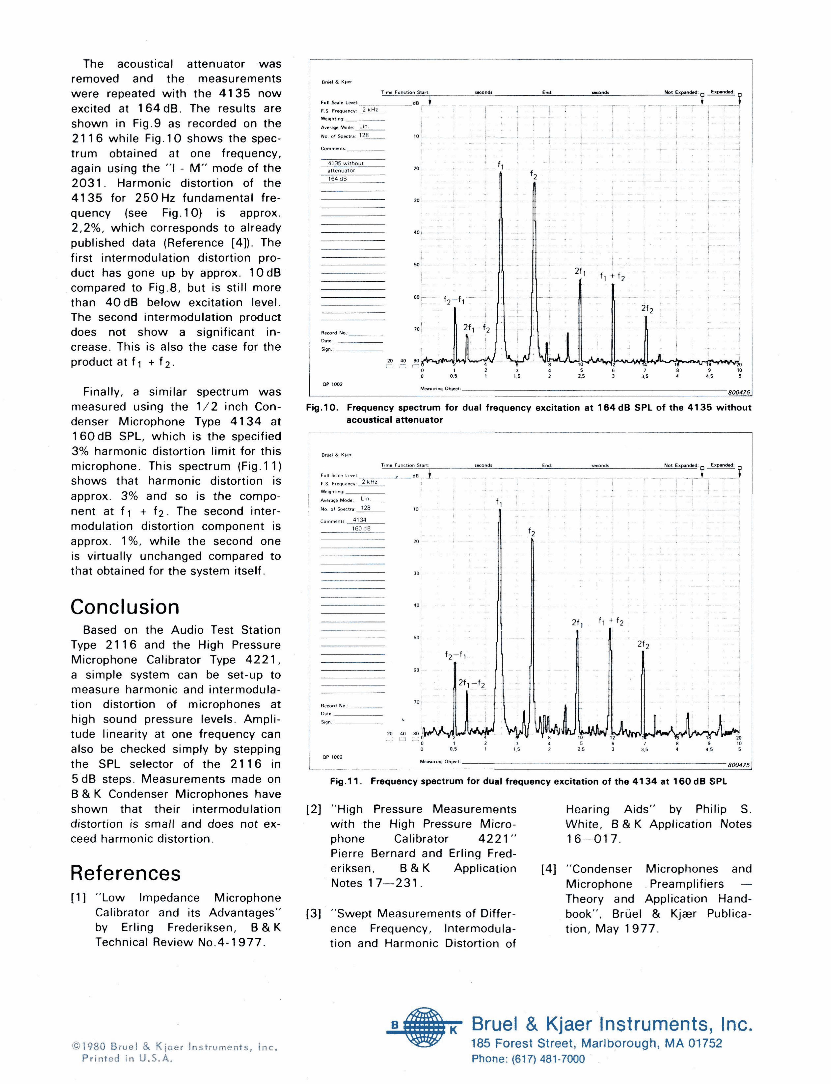
Fig.11. Frequency spectrum for dual frequency excitation of the 4134 at 1 6 0 d B SPL
[2] "High Pressure Measurements Hearing A ids" by Philip S. w i th the High Pressure Micro- White, B & K Application Notes phone Calibrator 4 2 2 1 " 16—017. Pierre Bernard and Erling Fred-eriksen, B & K Application [4] "Condenser Microphones and Notes 1 7 — 2 3 1 . Microphone Preamplifiers —
Theory and Application Hand-[3] "Swept Measurements of Differ- book", Bruel & Kjaer Publica-
ence Frequency, Intermodula- t ion, May 1977. tion and Harmonic Distortion of
Fig.10. Frequency spectrum for dual frequency excitation at 1 6 4 d B SPL of the 4135 wi thout acoustical attenuator
The acoustical attenuator was removed and the measurements were repeated wi th the 4135 now excited at 164dB. The results are shown in Fig.9 as recorded on the 2116 while Fig. 10 shows the spectrum obtained at one frequency, again using the " I - M " mode of the 2 0 3 1 . Harmonic distortion of the 4135 for 250 Hz fundamental frequency (see Fig. 10) is approx. 2,2%, which corresponds to already published data (Reference [4]). The first intermodulation distortion product has gone up by approx. 10dB compared to Fig.8, but is still more than 4 0 d B below excitation level. The second intermodulation product does not show a significant increase. This is also the case for the product at f i + f 2 .
Finally, a similar spectrum was measured using the 1/2 inch Condenser Microphone Type 4 1 3 4 at 160dB SPL, which is the specified 3% harmonic distortion limit for this microphone. This spectrum (Fig.11) shows that harmonic distortion is approx. 3% and so is the component at f 1 + f2 • The second intermodulation distortion component is approx. 1%, while the second one is virtually unchanged compared to that obtained for the system itself.
Conclusion Based on the Audio Test Station
Type 2116 and the High Pressure Microphone Calibrator Type 4 2 2 1 , a simple system can be set-up to measure harmonic and intermodulation distortion of microphones at high sound pressure levels. Amplitude linearity at one frequency can also be checked simply by stepping the SPL selector of the 2116 in 5dB steps. Measurements made on B & K Condenser Microphones have shown that their intermodulation distortion is small and does not exceed harmonic distortion.
References [1] "Low Impedance Microphone
Calibrator and its Advantages" by Erling Frederiksen, B & K Technical Review No.4-1 977 .