31
MICROPILE UNDERPINNING OVER EXPANSIVE PYRITIC SHALES Project: Evangelical Community Hospital, Lewisburg, Pennsylvania, USA Evangelical Hospital
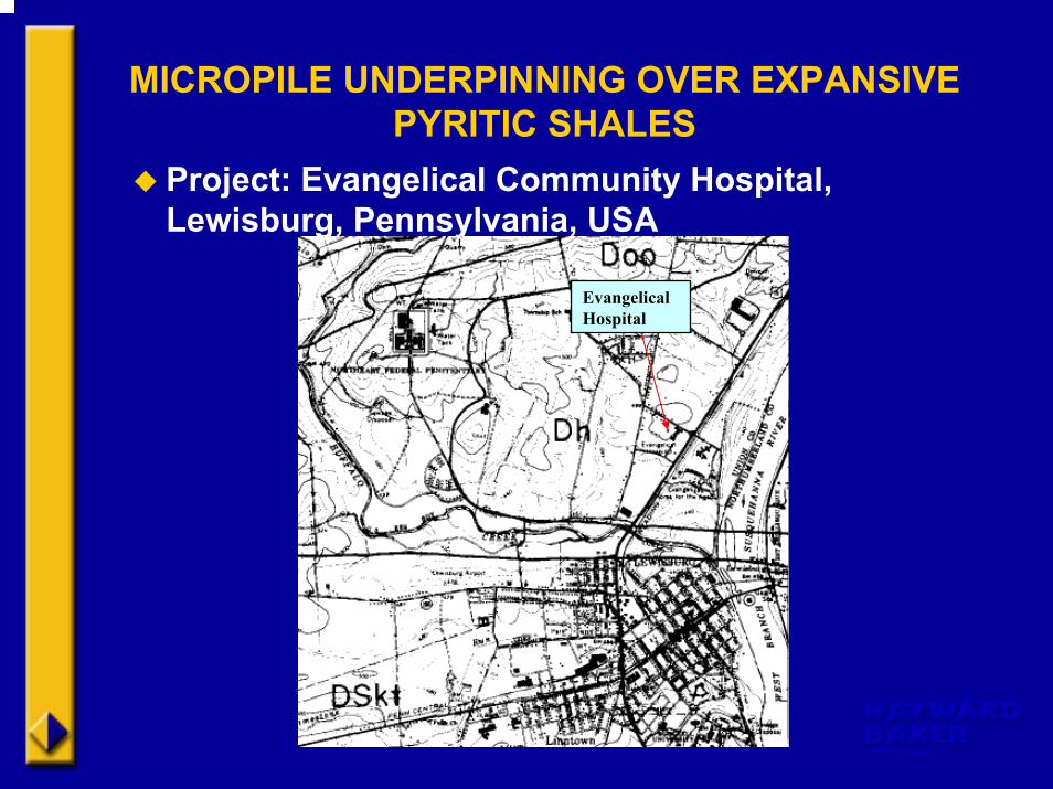
MICROPILE UNDERPINNING OVER EXPANSIVE PYRITIC SHALES
Project: Evangelical Community Hospital, Lewisburg, Pennsylvania, USA
Evangelical Hospital
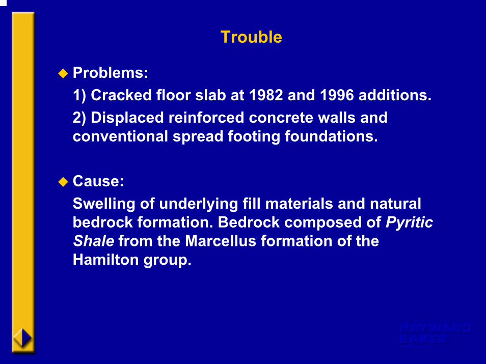
Trouble
Problems: 1) Cracked floor slab at 1982 and 1996 additions.2) Displaced reinforced concrete walls and conventional spread footing foundations.
Cause:Swelling of underlying fill materials and natural bedrock formation. Bedrock composed of Pyritic Shale from the Marcellus formation of the Hamilton group.

Expansive Pyritic Shales
Pyrite is found in black, carbonaceous shalesthroughout the world. Well-documented history of being potentially expansive. Heave due to the conversion of sulfides to sulfates. Pyrite oxidation occurs in two (2) settings: 1) Advective flow controls and oxygenated groundwater enters a layer containing pyrite.2) Diffusive O-2 flow dominates in the unsaturated zone and resulting sulfate and iron concentrations are huge and pH decreases to values close to 2.
The low pH values cause a variety of minerals to precipitate including gypsum and numerous ferric hydrosulfates.
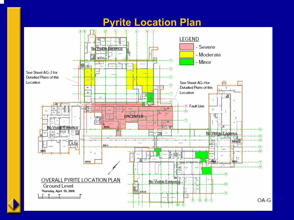
Pyrite Location Plan
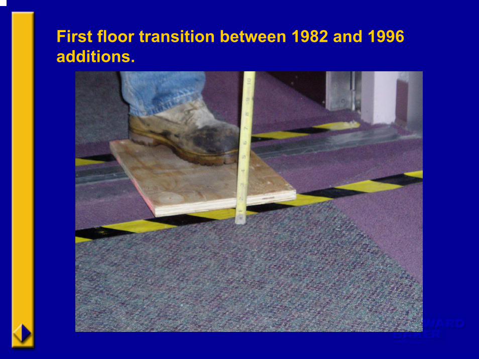
First floor transition between 1982 and 1996 additions.
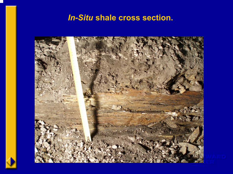
In-Situ shale cross section.
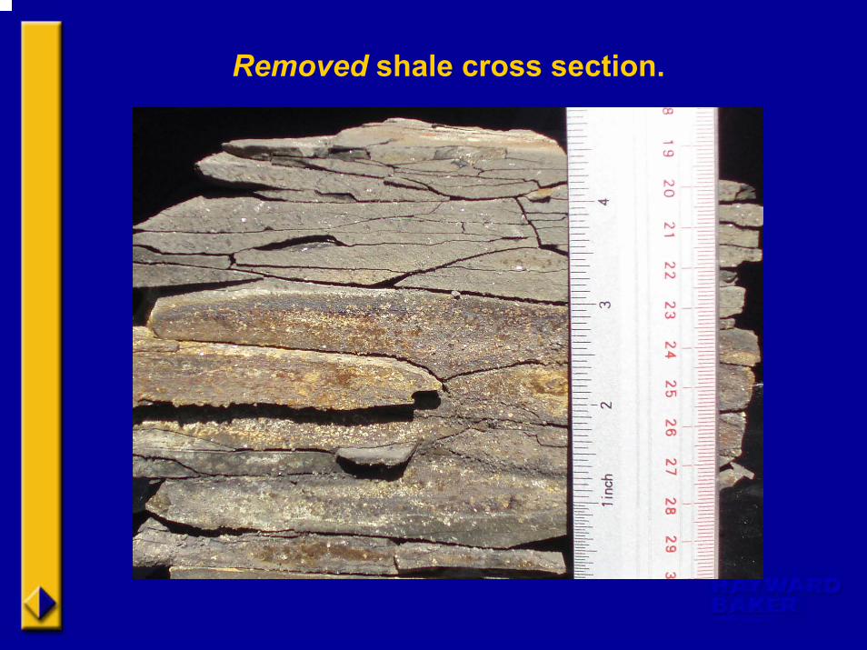
Removed shale cross section.
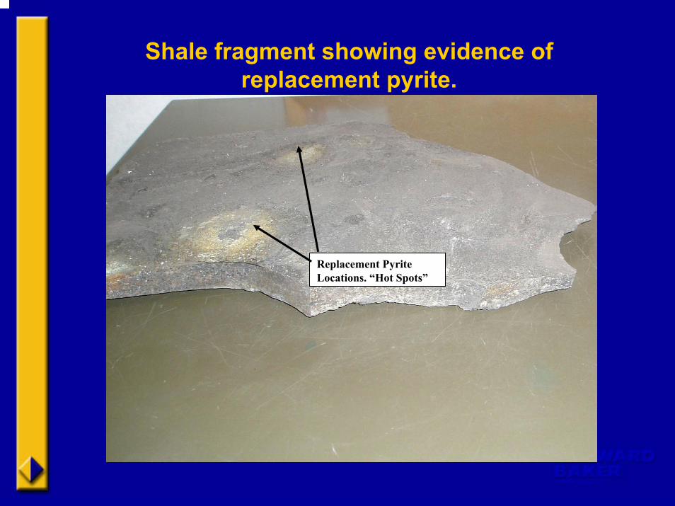
Shale fragment showing evidence of replacement pyrite.
Replacement Pyrite Locations. “Hot Spots”

Options?
Since there is no known method of treating the shales to limit future movement, and the heterogeneous nature of the shales precludes estimation of when the shales might stop expanding, underpinning the conventional foundations was the only viable option.
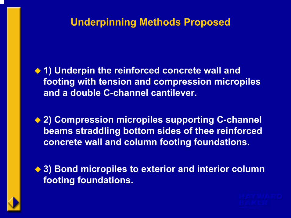
Underpinning Methods Proposed
1) Underpin the reinforced concrete wall and footing with tension and compression micropiles and a double C-channel cantilever.
2) Compression micropiles supporting C-channel beams straddling bottom sides of thee reinforced concrete wall and column footing foundations.
3) Bond micropiles to exterior and interior column footing foundations.
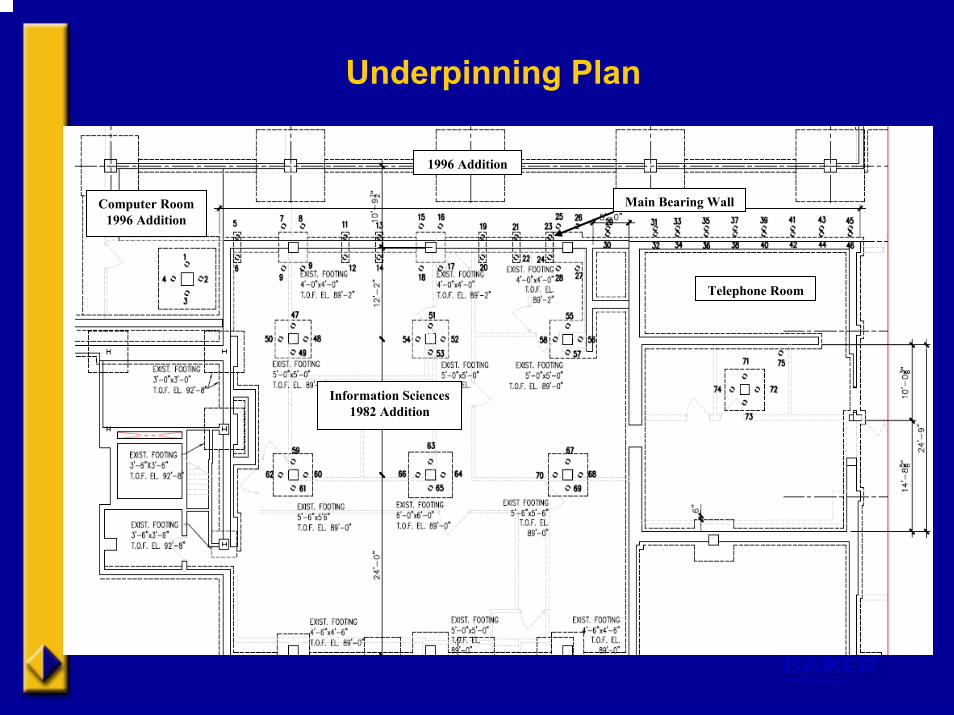
Underpinning Plan
Computer Room1996 Addition
1996 Addition
Main Bearing Wall
Telephone Room
Information Sciences1982 Addition
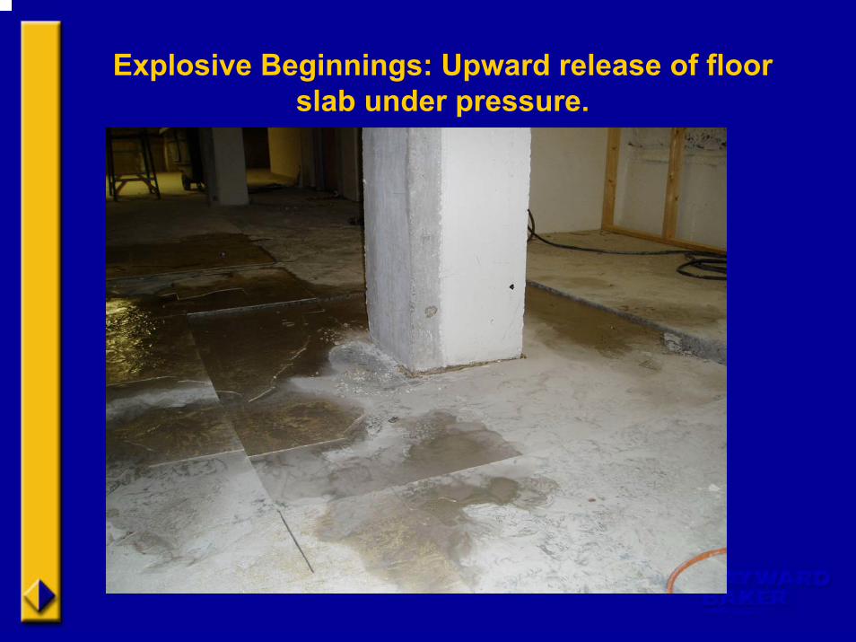
Explosive Beginnings: Upward release of floor slab under pressure.
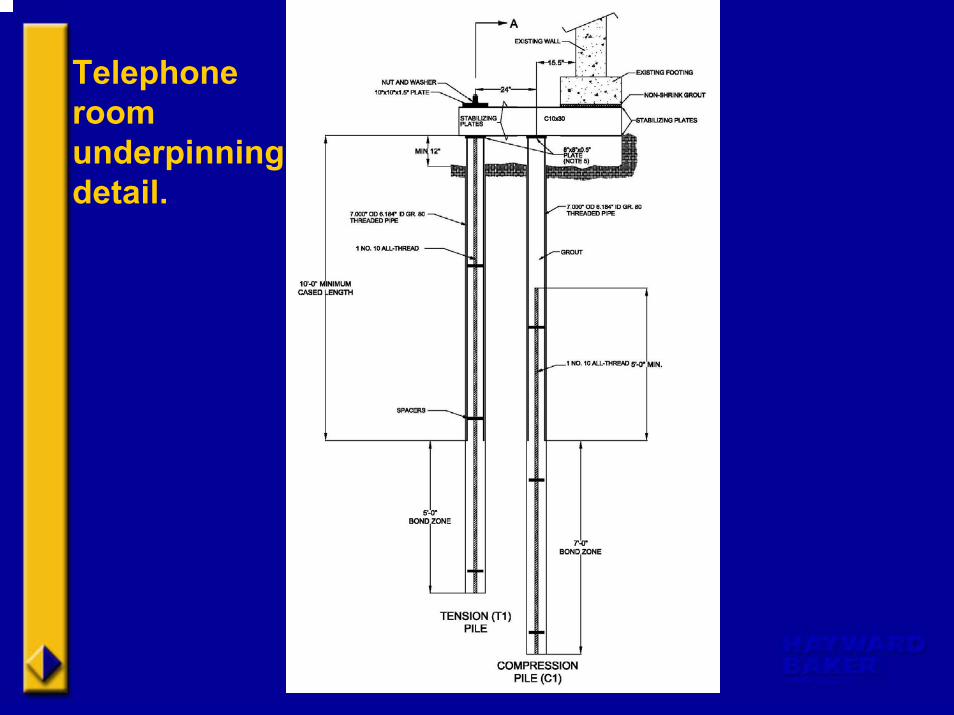
Telephone room underpinning detail.
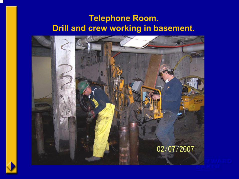
Telephone Room. Drill and crew working in basement.
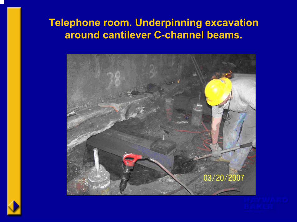
Telephone room. Underpinning excavation around cantilever C-channel beams.
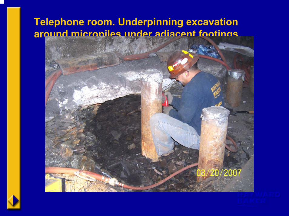
Telephone room. Underpinning excavation around micropiles under adjacent footings.
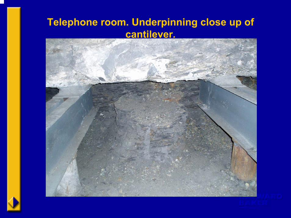
Telephone room. Underpinning close up of cantilever.
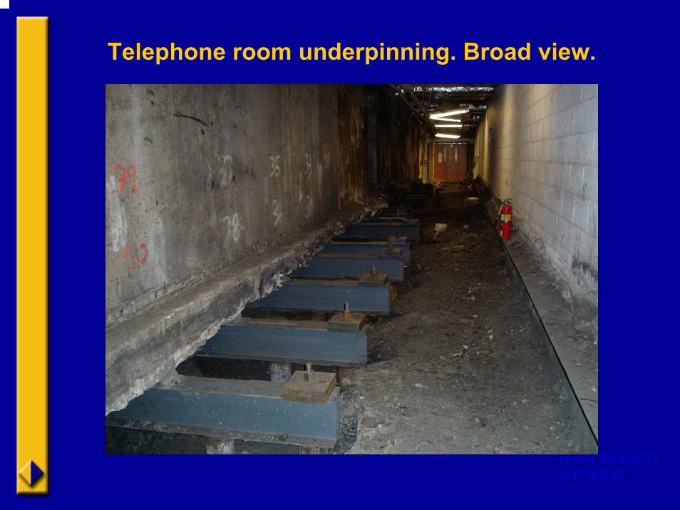
Telephone room underpinning. Broad view.
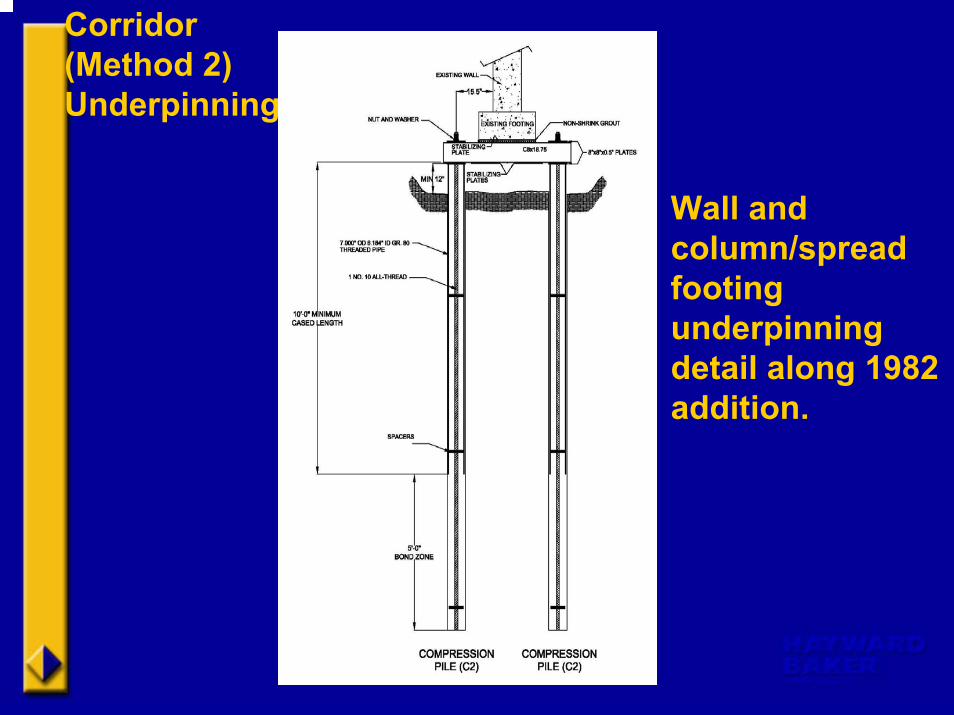
Corridor (Method 2) Underpinning
Wall and column/spread footing underpinning detail along 1982 addition.
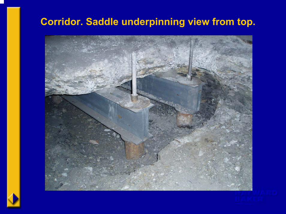
Corridor. Saddle underpinning view from top.
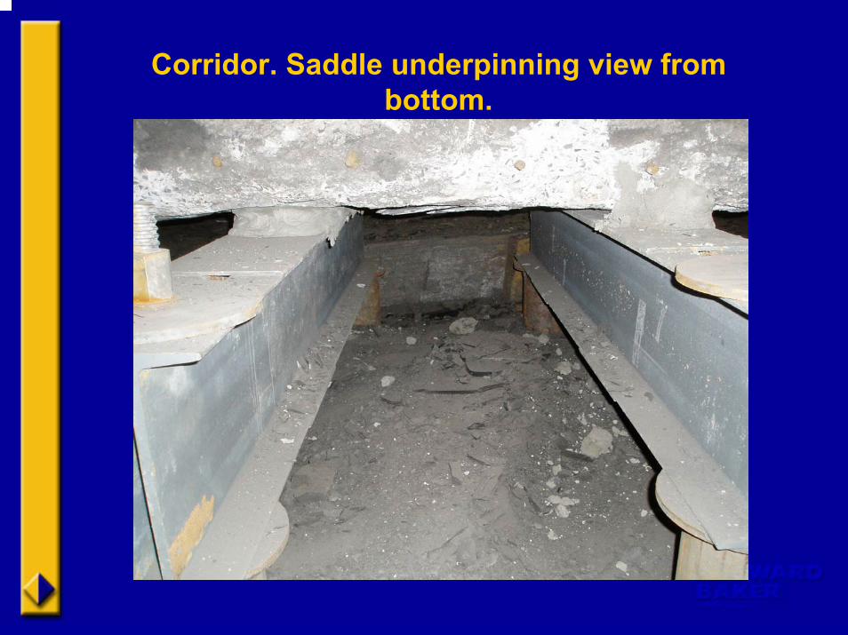
Corridor. Saddle underpinning view from bottom.
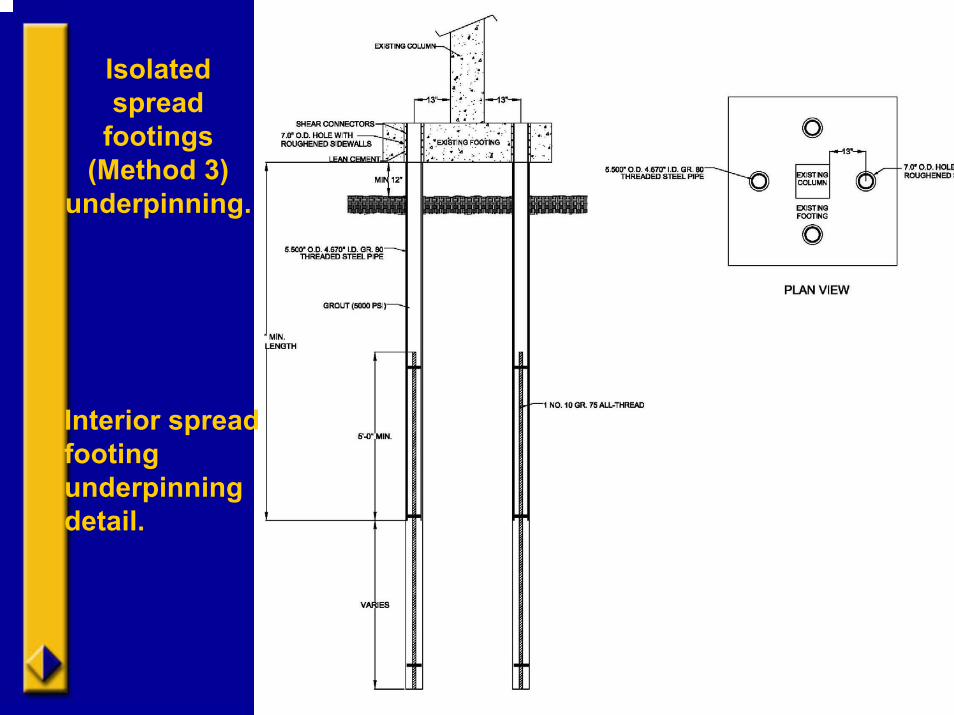
Isolated spread
footings (Method 3)
underpinning.
Interior spread footing underpinning detail.
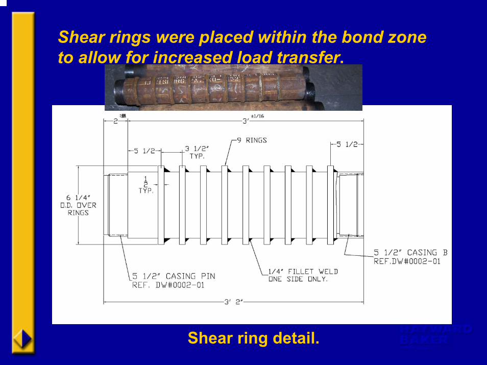
Shear rings were placed within the bond zone to allow for increased load transfer.
Shear ring detail.
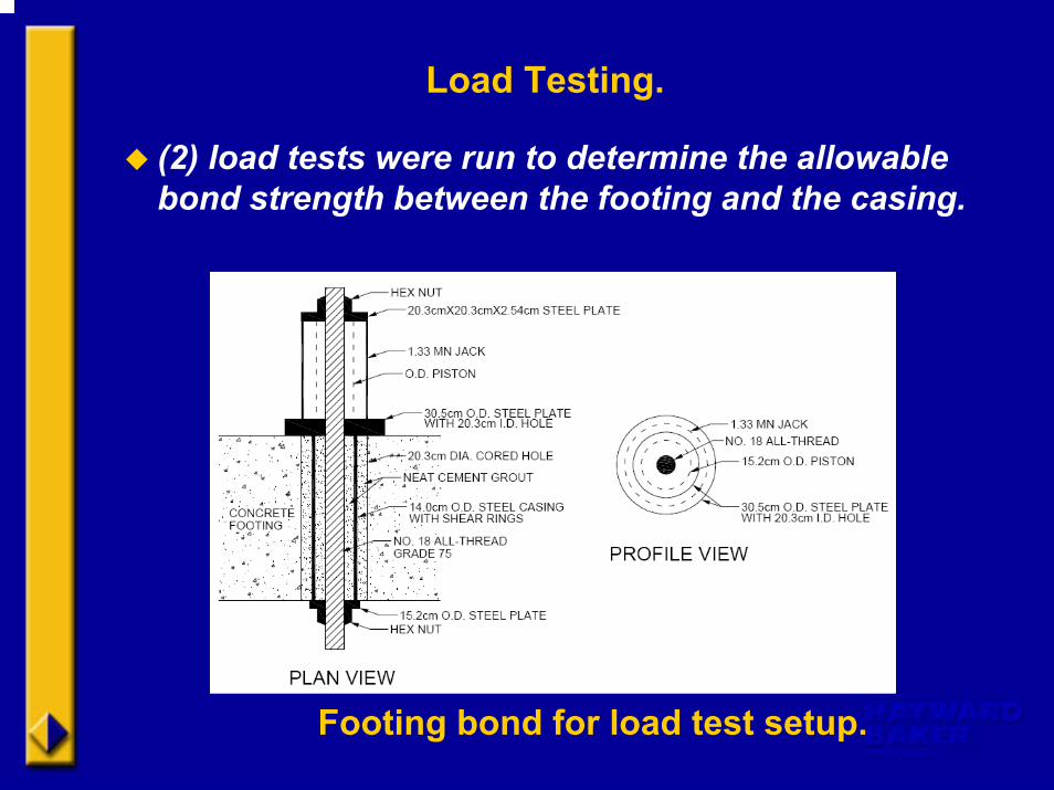
Load Testing.
(2) load tests were run to determine the allowable bond strength between the footing and the casing.
Footing bond for load test setup.
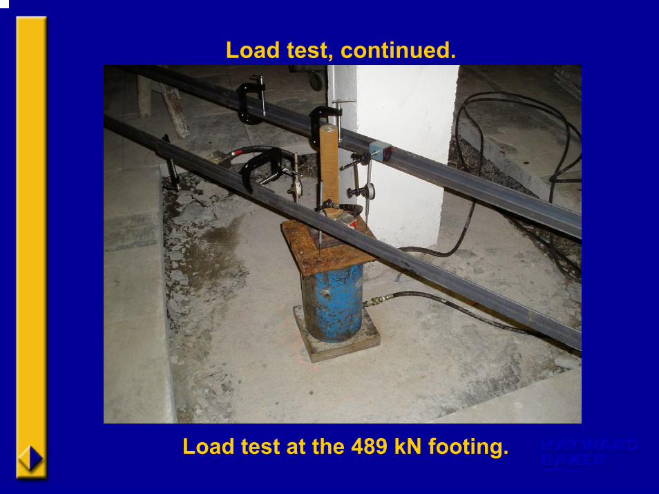
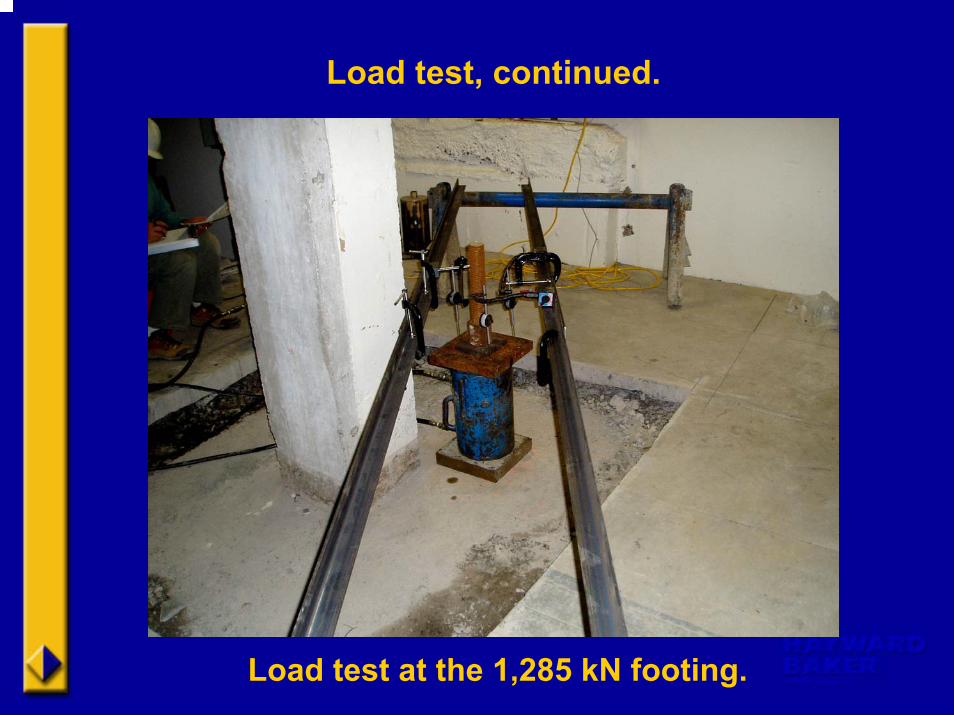
Load test, continued.
Load test at the 489 kN footing.
0
0.02
0.04
0.06
0.08
0 20 40 60 80 100 120 140 160
LOAD (KIPS)
ELO
NG
ATI
ON
(IN
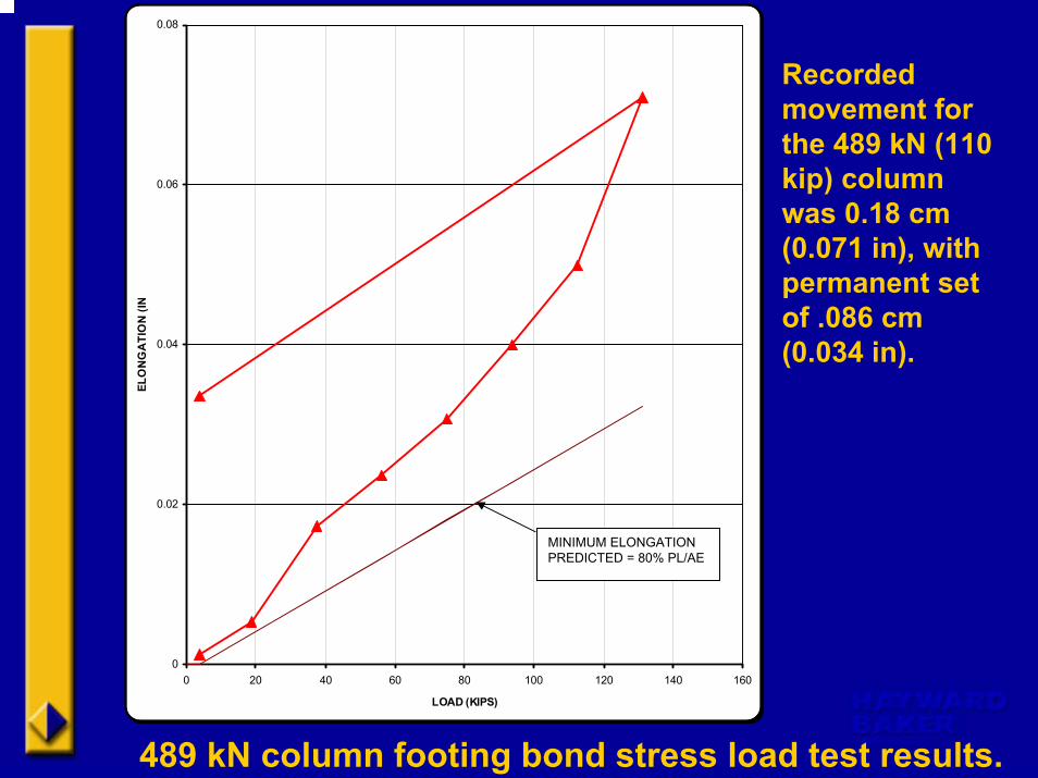
489 kN column footing bond stress load test results.
Recorded movement for the 489 kN (110 kip) column was 0.18 cm (0.071 in), with permanent set of .086 cm (0.034 in).
MINIMUM ELONGATION PREDICTED = 80% PL/AE
Load test, continued.
Load test at the 1,285 kN footing.
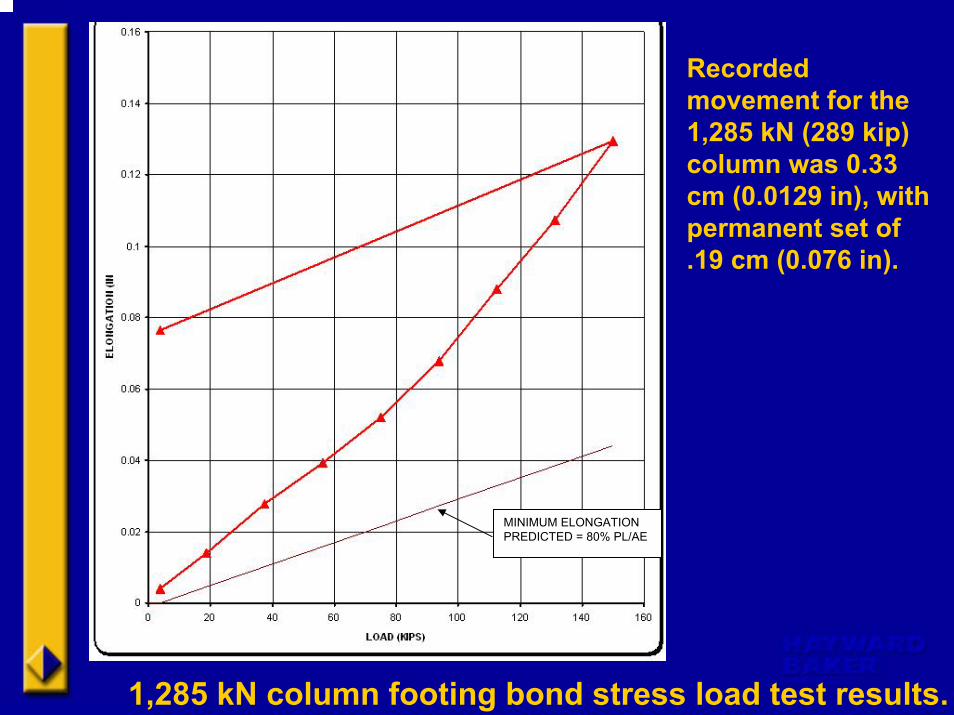
Recorded movement for the 1,285 kN (289 kip) column was 0.33 cm (0.0129 in), with permanent set of .19 cm (0.076 in).
1,285 kN column footing bond stress load test results.
MINIMUM ELONGATION PREDICTED = 80% PL/AE
Load tests, cont.
The results of these tests were considered satisfactory by the project team.
Unforseen Conditions
Overexcavation after micropile installation in the Information Sciences room of the 1982 addition revealed:
1) Footings were not poured symmetrically around the columns. Offset by as much as 30.5 cm from the locations on the project drawings.
2) One of the footings was basically nonexistemt on the northern side of the reinforced concrete col.
3) Four (4) of the seven (7) column footings had one or more locations where there was not sufficient distance from the edge of the micropile to the edge of the footing.