Microplane constitutive model and metal plasticity Michele Brocca and Zdenek P Bazant Department of Civil Engineering and Materials Science, Northwestern University, Evanston IL; [email protected]
The microplane model is a versatile constitutive model in which the stress-strain relations are dermed in tenns of vectors rather than tensors on planes of all possible orientations, called the microplanes, representative of the microstructure of the material. The microplane model with kinematic constraint has been successfully employed in the modeling of concrete, soils, ice, rocks, fiber composites and other quasibrittle materials. The microplane model provides a powerful and efficient numerical tool for the development and implementation of constitutive models for any kind of material. The paper presents a review of the background from which the microplane model stems, highlighting differences and similarities with other approaches. The basic structure of the microplane model is then presented, together with its extension to fmite strain defonnation. Three microplane models for metal plasticity are introduced and discussed. They are compared mutually and with the classical Jrflow theory for incremental plasticity by means of two examples. The first is the material response to a nonproportional loading path given by uniaxial compression into the plastic region followed by shear (typical of buckling and bifurcation problems). This example is considered in order to show the capability of the microplane model to represent a vertex on the yield surface. The second example is the 'tube-squash' test of a highly ductile steel tube: a finite element computation is run using two microplane models and the Jrflow theory. One of the microplane models appears to predict more accurately the final shape of the deformed tube, showing an improvement compared to the J2-flow theory even when the material is not SUbjected to abrupt changes in the loading path direction. This review article includes 114 references.
1 INTRODUCTION
Over the past two decades, the microplane model has been successfully used by Baiant and coworkers to model the mechanical behavior of quasibrittle materials such as concrete, soils, rocks, ice, fiber composites, stiff foams and shape memory alloys [see eg, Baiant (1984), Baiant and Prat (1988a,b), Carol and Baiant (1997), Brocca et al (1999a,b)]. Several practical applications (eg, large-scale finite element analysis of concrete structures at WES) have shown the efficiency and accuracy of the model.
In a microplane model, the stress-strain relations are defined in terms of vectors rather than tensors independently on planes of many different orientations, called the micro planes , approximately representative of the microstructure of the material. The stress and strain components on a particular microplane are called the microplane stress and strain components. The overall macroscopic behavior, in terms of the usual macroscopic stress and strain tensors, is obtained by superimposing the effects of all the microplanes.
One appealing aspect of this approach is that it provides the researcher with an efficient theoretical and numerical framework, within which the constitutive law is simple. Once the general algorithm for dealing with the relationship between microplane quantities and macroscopic stress and strain tensors has been established, fonnulating a constitutive law is conceptually simple and intuitive, since all the quantities involved have always an immediate physical meaning.
Transmitted by Associate Editor F Ziegler
ASME Reprint No AMR295 $18
In this article, we will discuss three different models for metal plasticity developed with the microplane approach. We will also present a theoretical comparison of the microplane model with the major existing phenomenological and crystallographic models of metal plasticity. Such a comparison is particularly meaningful in this case, because the original theoretical background from which the microplane model stems was historically developed in the field of metal plasticity for polycrystalline metals. We will review the approaches and models most widely used in this field and will try to clarify the differences and similarities with the microplane model. We will show in the following that the microplane model stands somewhere in between the two extremes represented by phenomenological and crystallographic models and can thus be considered a semi-phenomenological model.
Finally, we will compare quantitatively the microplane model and the classical Jrflow theory, by considering two numerical examples: material response for a non-proportionalloading path with a sudden change in direction and the tube-squash test on a ductile steel carried out at Northwestern University.
2 REVIEW OF MAJOR EXISTING MODELS FOR METAL PLASTICITY
Metal plasticity is usually modeled following two major approaches: a crystallographic one, which is based on· inicro-
266 Brocca and Bazant: Microplane constiMive model and metal plasticity Appl Mech Rev vol 53, no 10, October 2000
mechanical considerations and tries to reproduce closely the physical phenomena whose macroscopic manifestation is plastic deformation, and a phenomenological one, wherein plastic deformation is characterized in terms of the stress and strain tensors and their invariants. The latter approach is completely unrelated to the microscopic mechanisms of plastic deformation.
The crystallographic theories can be classified into two main groups: Taylor models and self-consistent models. Section 2.1 will review the Taylor models and briefly address the self-consistent models.
Another approach that draws inspiration from cl)'lltallographic experimental observation, is the slip theory of plasticity, proposed by Batdorf and Budiansky (1949) as an adaptation of the idea of Taylor(1938). This approach differs from the strictly crystallographic ones, because the material is modeled as a continuum, neglecting the crystalline structure and the anisotropy of the lattice. The slip theory of plasticity will be reviewed in Section 2.2. The microplane model is an adaptation and generalization of the slip theory of plasticity.
The most common phenomenological theory for elasticplastic deformation of metals is the Prandtl-Reuss flow theory with isotropic hardening, or Jrflow theory. A modification of this theory, which allows more accurate predictions of material response in the case of sudden changes of loading path direction, is the J2-corner theory of Christoffersen and Hutchinson (1979). The phenomenological theories and methods will be briefly discussed in Section 2.3.
"',
2.1 Crystallographic models
The models reviewed in this section assume that the microscopic source of plastic deformation is crystallographic slip. Such assumption is based on physical considerations. These models produce large strain constitutive laws that can be used to interpret experiments on large strain plastic behavior of metals. They also provide a basis for formulating phenomenological constitutive laws (eg, Christoffersen and Hutchinson (1979) used the results from Hutchinson's (1970) smaIl-strain, rate-independent polycrystal calculations to specify comer characteristics in their J 2-corner theory).
The idea for the crystallographic approach to material modeling was inspired by experimental observations of crystallographic behavior of metals. Single crystal tests by Taylor and Elam (1923, 1925, 1926) showed that under high stress, slip occurs on certain crystallographic planes along certain directions. They observed that slip on a given plane depends on the resolved shear stress on that plane and is independent of the normal stress on the plane. The stress at which slip occurs is called the critical stress. The increase of the critical stress with the magnitude of slip is known as strain hardening, while latent hardening is the increase in critical stress in unslipped systems.
Taylor (1934) showed in his dislocation theory that sliding occurs in such a manner that perfect crystal structure is reformed after each atomic jump. The lattice structure of the bulk of the material remains essentially the same after the occurrence of slip, hence the elastic modulus remains the same. The elastic strain is caused by the elastic deformation
of the lattice structure, and the plastic strain is caused by the movement of dislocations. A discussion of the dislocation mechanism background of this continuum slip description of plastic flow is given by Asaro (1983a).
The Taylor-type models and self-consistent schemes explicitly represent the deformation by crystallographic slip in polycrystals. Polycrystals are continuous three-dimensional collections of grains (ie, crystallites), each of which can deform by the mechanism of crystallographic slip. Taylor (1938) proposed a model that strictly enforces compatJ.bility by imposing the same set of strains (aggregate strains) on each grain. This idea comes from the experimental observation that most grains of a polycrystal undergo about the same strain.
Taylor (1938) used his model to analyze simple tension or compression of single phase FCC (face-centered cubic) polycrystals. In Taylor's numerical calculations, the polycrystal is made initially isotropic by choosing the grains to have a uniform coverage of all crystallographic orientations. The only source of inelastic deformation is assumed to be the crystallographic slip. The calculation is then based on determining the combination of slip systems and corresponding shear strains and stress state in each grain required to produce the specified strain. The selection of slip systems required to produce an arbitrary strain is not necessarily unique. Taylor made the physically intuitive assumption that among all the possible choices for combinations of active slip systems, the appropriate choice was that for which the cumulative shears are minimized. (actually that for which the net internal work is minimized, which reduces to minimization of cumulative shears if all the shear systems have same shear strength and hardening). Taylor could predict textures in FCC crystals in agreement with experiments ofaxisymmetric tension and compression.
Bishop and Hill (1951) proposed a polycrystal theory based on the principle of maximum work. They used inequalities between external work, computed as the product of macroscopic stress and strain increments, and internal work, computed as the integral over the volumes of grains of the products of the crystallographic shear strength and assumed slip increments, to set bounds on the critical stress state required to induce yield. Their primary interest was to determine yield surfaces.
The Taylor type models have been extensively used in the past 50 years to predict texture development and stress strain response. The development in this field is in the direction of increasing complexity, but most of the models retain the basic assumptions and structure of the Taylor model. We will now outline the common assumptions and the basic formulation of the Taylor model, as developed and used, among others, by Rice (1971), Hill and Rice (1972), Asaro and Rice (1977), Asaro (1983b), Asaro and Needleman(1985), Harren et al (1989), and Bronkhorst et al (1992).
The stress response at each macroscopic continuum material point is given by the volume-averaged response of the multitude of microscopic single crystalline grains comprising the material point. It is assumed that all the grains have equal volume, and that the local deformation gradient in each grain is homogeneous and identical to the macroscopic deforma-
Appl Mech Rev vol 53, no 10, October 2000 Brocca and BaZant Microplane constitutive model and metal plasticity 2fil
tion gradient F at the continuum material point. The mechanics of crystal deformation by slip is represented in two parts: the plastic deformation is given by a set of plastic simple shears from the reference configuration on the slip system of the crystallite, and the lattice with its embedded material elastically deforms and rigidly rotates from this plastically sheared state to reach· the current configuration [Rice (1971), Asaro and Rice (1971)]. The deformation gradient tensor F is therefore decomposed as
F=FP (2.1)
where tensor P describes the material shear flow along the various slip systems of the crystallite, and tensor F describes the elastic distortion of the lattice along with the rigid rotation of the crystallite.
The plastic shear flow from the reference configuration is written as
LP = F P F p'1 = I yea) sea) m (a) (2.2) a
where yea) is the shear rate on slip system a. The slip system a is def'med by the unit crystallographic vectors i a
) and mea), where i a) is the direction of slip in the actual configuration and mea) is normal to the slip plane in the actual configuration. The plastic response of a crystallite is defined in terms of the resolved shear stress on each slip system. Each of the slip systems is active as long as the resolved shear stress on that system does not vanish. The plastic shear rate on the slip system a is taken to be governed by a constitutive function of the form
(2.3)
where 'tea) is the resolved shear stress for the slip system a, and g(a) is the shear resistance of the slip system a. This equation can be given in the form of a power law (Hutchinson (1965), Pan and Rice (1983), Pierce et al (1983)].
An evolution law can be given for g(a) in the form
g(a) = Iha~IY(~)I, (2.4) ~
where haf> is the rate of strain hardening on slip system a due to shearing on the slip system ~ (latent hardening is thus taken into account).
The elastic response of the crystallite is governed by the elastic moduli set up to take into account the anisotropy due to crystallite orientation. In some cases, researchers consider the elastic response of polycrystalline aggregate, but neglect the elastic anisotropy of the FCC single crystal, and the elasticity tensor is the usual elasticity tensor.
Once the behavior of a crystallite is defined, the constitutive response of a polycrystalline aggregate is obtained using an averaging scheme [described in Hill (1972), and Asaro and Needleman (1985)].
The foregoing constitutive model can be used in two types of finite element calculations: 1) Those where the integration point represents a material
point in a polycrystalline sample and the constitutive re-
sponse is given through a Taylor-type polycrystal model; and
2) those where the integration point represents a material point in a single grain and the constitutive response is given through a single crystal model without invoking the Taylor assumptions. In this second kind of computation both equilibrium and
compatibility are satisfied in a weak finite element sense. In Taylor-type computations, the compatibility is satisfied, but not eqUilibrium between grains.
Bronkhorst et al (1992) presented an evaluation of the Taylor model, done by comparing finite-element results to experimental results. They concluded that the Taylor-type model is in a reasonable first order agreement with the observation of the texture formation and also with the overall stress-strain response of single-phase copper. Some deficiencies in the prediction from the Taylor model (finite element computations of the first kind) may be a consequence of the strong kinematic constraint on the deformation of the individual grains of the polycrystal in this model. In the finite element computations of the second kind, the constraint on the deformation of the individual grains is relaxed and the computation is run using initially random grain orientations. In this second case each element represents a single grain. When such an approach is adopted, a typical orange peel effect can be observed on the unconstrained surfaces of the FE mesh. This is caused by differences in the orientations of the grains that intersect the free surfaces, and is observed also in physical experiments.
To improve the performance of the· model, the strong kinematic constraint characteristic of the Taylor model can be relaxed, by introducing intergranular constraint relations of various sorts. Butler and McDowell (1998) presented a reformulation of the kinematics of the plastic velocity gradient, introducing a new concept for taking into account the grain subdivision using additional plastic rotation associated with generation of the geometrically necessary dislocations. The modeling of grain subdivision is motivated by the recent experimental studies of microtexture formation [Hughes and Hansen (1993), Hughes (1995)]. The subdivision process facilitates adherence to the Taylor ·assumption of uniform deformation at the scale of individual grains. Butler and McDowell (1998) introduce a generalization of the decomposition of F
F=FPP (2.5)
which includes a part, P, that is associated with the subdivision, distinct from the contribution of dislocation glide, P. Here, F = Rlf includes the elastic stretch and, for small elastic strains, essentially rigid rotation relative to the lattice.
Another way to tackle the problem of excessive kinematic constraint in Taylor assumption is by enforcing the so-called relaxed constraints (RC) to reflect the inhomogeneity of strain from grain to grain that is expected to develop ~th increasing deformation. When grains become too distorted, enforcement of stress equilibrium rather than full compatibility may perhaps be more reasonable; this is taken as the basis of
268 Brocca and BaZant: Microplane constiMive model and metal plasticity Appl Mech Rev vol 53, no 10, October 2000
theRC model [Honneff and Mecking (1978), Canova, Kocks, Jonas (1984), Rollet et al (1989)].
Another approach to polycrystal modelling is the selfconsistent scheme suggested for this purpose by KrOner (1961), Budiansky and Wu (1962) and Hill (1965). This approach produces rate-independent models which attempt to account for grain interaction by considering each grain to be an inclusion embedded in an infinite homogeneous matrix whose moduli are the overall moduli of the crystal to be determined as an average over all grains. Hutchinson (1970) used this approach to determine the yield surfaces and stressstrain response for uniaxial tension and for uniaxial tension followed by shear (1970).
Brown (1970) and Berveiller and Zaoui (1979) extended the self-consistent models to account for rate dependence. In self-consistent models, the assumption of identical grain deformation is relaxed and these models also account, approximately, for intergranular equilibrium. They do so by enforcing equilibrium between the individual grains and the aggregate average. However, in self-consistent models as well as in Taylor type models, the deformation within each grain is presumed homogeneous.
2.2 Slip theory of plasticity
The slip theory, introduced by Batdorf and Budiansky (1949), assumes the plastic slip to be the only source of plastic deformation. The slip in any direction along parallel planes of any particular orientation in the material gives rise to a plastic shear,strain, which depends only on the history of the corresponding component of shear stress. The plastic strain due to any system of applied stress is found by: 1) considering the history of the component in each direction
of the shear stress on each plane of the material, 2) finding the corresponding plastic shear strain, 3) transforming this plastic shear strain into plastic strains in
some fixed system of coordinates, and 4) summing over all the slip directions and slip plane orien
tations. In their original paper, Batdorf and Budiansky proposed a semigraphical method for the computations. The shear stress required to produce slip is assumed to be
independent of the normal stress and the amount of slip. The plastic shear deformation resulting from slip on a plane of a given orientation depends only upon the history of the component of the shear stress in the direction of slip on that plane.
Batdorf and Budiansky's approach differs substantially from the Taylor-type models and self-consistent models in that it neglects the actual crystallographic structure of the material and the anisotropy that it implies. The metal is modeled by considering it to be a macroscopically isotropic continuum, and slip is possible on a plane of any direction at any given point, and not only on the planes whose orientation is determined by crystallographic considerations. The theory contemplates an infinitesimal plastic shear strain associated with each infinitesimal fraction of the continuum comprising all possible planes. Given a plastic shear strain on a given plane, the contribution of this infinitesimal shear strain to the strains in the macroscopic reference system can be expressed . by projecting the shear strain along the x, y, z directions.
The initial critical shear stress for slip on a plane is given by Yz of the elastic limit in pure tension or compression, since in tension test the maximum shear stress is Yz of the applied uniaxial stress. Beyond this initial value, the critical stress increases according to a characteristic shear function to be determined experimentally, from tests on the polycrystalline continuum, not on the single crystal. The slip theory of plasticity can therefore be considered to be semiphenomenological, since the assumed mechanism of plastic deformation is suggested by crystallographic observation. But the mathematical description of slip is derived in a phenomenological way.
Batdorf and Budiansky showed that their slip theory yields more accurate predictions than the deformation theory of plasticity or the Jrflow theory in the cases characterized by an abrupt change in the loading path. They considered tests on thin aluminum alloy cylinders, compressed into the plastic range and then twisted while the compressive strain is held constant.
2.3 Phenomenological models
The simplest and most commonly used phenomenological theory for infinitesimal elastic-plastic deformation· of polycrystalline metals is the classical, rate-independent, PrandtlReuss flow theory with isotropic hardening based on the von Mises yield criterion reg, Hill (1950)]. This classical rateindependent model has been generalized to finite deformation and a frame indifferent form by Hill (1958, 1959). The rate-independent 'plasticity has been studied, among others, by Hibbitt et al (1970), Needleman(1972), and Osias and Swedlow (1974).
The numerical implementation of the infinitesimal strain version of the rate-independent model into displacementbased finite element procedures dates back to the 1960s (Wilkins, 1964), and the study of the numerical implementation of the finite-strain, frame indifferent version of the rateindependent and rate-dependent models started in the following decade [McMeeking and Rice (1975), Hughes (1984), Needleman (1984), Anand (1982, 1985), Brown et al (1989), etc]. These models usually employ the additive decomposition of the stretch tensor into elastic and plastic parts. For a numerical implementation of a model based on multiplicative decomposition of the deformation gradient into elastic and plastic parts, see Weber and Anand (1990).
These finite deformation constitutive models are in essence extensions of the small-strain isotropiC hardening plasticity models, and therefore they are t;xpected to provide accurate descriptions of the deformation behavior of initially isotropic materials only up to deformation levels where significant anisotropy in the metal has not yet developed.
The criterion for physical soundness of a plasticity theory (leaving aside damage mechanics) is assumed to be the satisfa«tion of Drucker's postulate. Drucker (1951) proposed a definition of work-hardening on the basis of some quasithermodynamic arguments. This led to the following two inequalities:
(2.6)
Appl Mech Rev vol 53, no 10, October 2000 Brocca and BaZant: Microplane constiMive model and metal plasticity 269
(2.7)
where (Jij is the current stress state on the yield surface S and
cr~. is any other stress state in E (elastic region). The second lJ
inequality is called the principle of maximum plastic work
by Bishop and Hil1(1951) who prove it for single crystals
that deform plastically by slip. Inequality (2.7) has the fol
lowing two consequences:
I) the yield surface is convex;
2) If the current stress state (Jij is on S and S is smooth at (Jij,
then, for any given loading crij, the direction of the strain
rate vector ef. IIlust be that of the exterior normal to the y
yield surface at (Jij'
If S is not smooth at (Jij (there is no unique normal at (Jij to
surface elements of S), then ef} must merely point toward
the cone of normals to Sat (Jij'
It is well known that the classical theory of the PrandtlReuss flow rule (with an isotropically hardening smoOth von Mises yield surface), ie, the J2-flow theory, yields resuhs in disagreement with the prediction of crystallographic slip models. The crystallographic slip Inodels predict the existence of comers ( 01' vertices) on the yield surface and thus a dependence of the plastic strain rate on the direction of the rate of stress. This is called the vertex effect. In the J2-flow theory, on the other hand, the plastic strain rate is always normal to the von Mises yield surface.
The simplest vettex model for plasticity is the hypoelastic deformation theory ofStOren and Rice (1975). In this theory, the plastic strain rate is not necessarily normal to what would be the von Mises yield surface. Being a deformation theory, it is not directly applicable to plastic loading paths that exhibit significant deviation from proportionality.
The Jrcorner theory of Christoffersen and Hutchinson (1979) eliminates this restriction. In this theory, the yield surface vertex is modeled as a stress space hypercone. For plastic \o~g along paths that coincide or nearly coincide with proportional loading, the response is talcen as that of hypoelastic deformation theory. This regime of behavior is called the total loading. Elastic unloading occurs when the direction of the stress rate lies in or within the cone surface. For loading paths that lie between total loading and elastic unloading, the Christoffersen-Hutchinson theory provides a region of transitional response where the instantaneous moduli smoothly increase from the deformation theory Inoduli of the total loading regime to the linear elastic moduli of the unloading regime. The Jrcomer theory has been extended by Hutchinson and Tvergaard (1980) to include hyperelastic total loading response. A discussion about methods for endowing the ~en~ incremental theory of plasticity with a vertex was also gIVen m BaZant (1980, 1987).
The high CUlVature of the yield surface in the neighborhood of its current loading point can be described to some e")(.tent by the classical theory of kinematic hardening. Contributions in this sense have been given, among others, by Lee et al (1983), Dienes (1979), Key (1984), Fressengeas and Molinari (1985). Harren et at (1989) compare the poly-
crystal predictions to predictions based on phenomenological vertex-type descriptions. They do so by performing large shear calculations with J2-corner theory and two versions of kinematic hardening theory. For plane strain incompressible deformation, the J 2-corner theory and the FressengeasMolinari kinematic hardening theory agree well with polycrystal predictions.
A different phenomenological representation, which more closely reflects the physical origin of the vertex effect, was given by Sewell (1974), who used the theory of multiple yield systems, introduced by Koiter (1953), Mandel (1965) and Hill (1966). The formulation for multisurface plasticity develops from the assumption that, at each state, the plastic strain consists of several components,
(l.&)
each of them governed by a different yield surface. This formulation yields in principle a rather realistic description of material behavior, but it . is not easy to apply because identification of the material parameters from test data is difficult [see also eg, BaZant and Cedolin (1991)].
In the 1970s, another approach has received consid~le attention: the endochronic theory reg, valanis (1971), BaZant (1978, 1980)]. The basic concept in the endochronic fonnulation is the characteritation of inelastic strains in terms of one (or several) non-decreasing scalar variables whose increments depend on the strain increments. This variable is generally called the intrinsic time although it doesn't necessarily (and normally) correspond to physical time. Similar to vertex hardening models and the deformation theory of plasticity, the endochronic theory gives inelastic strain for strain inc.rero.ents that are tangential to the current loading surface. However, in contrast to vertex hardening, the endochronic inelastic strain for tangential .strain increments is normal to the loading surface. Consequently, the endochronic theory is stiffer than vertex hardening for this loading direction. Although the endochronic approach is very convenient for describing hysteresis, it is purely phenomenological, with nr clear physical basis, and seems to have lost popularity.
The J2-flow theory will serve in Section 6 as a reference for the numerical evaluation of the microplane models for plasticity. The most common ways of ilnplementing nUIIlerically the Jrflow theory are finite strain extensions of the algorithm developed by Wilkins in 1964. Two algorithms bave been used for comparisons with the microplane model: one presented by Hughes (1984) and the other one by Ponthot (1995). They are based on two different ways of approximating the incremental strain at each time step. Both approaches employ the radial return algorithm [presented by Wilkins (1964) and generalized by Krieg and Key (1976)]. In the examples considered here, the two algorithms yield nearly identical results.
3 REVIEW OF MICROPLANE MOJ)EL
The aricroplane model developed by BaZant and coworkers is an evolution and generalization of Batdorf and Budiansky's approach. It was first used to model concrete, rocks, and soils.
270 Brocca and Bazant: Microplane constitutive model and metal plasticity Appl Mech Rev vol 53, no 10, October 2000
Carol and Baiant (1997) pioneered the microplane models for plasticity. In this paper, three new models for plasticity within the microplane model framework are formulated. .
3.1 History of microplane model
The background history of the microplane model can be traced back to the pioneering idea of GI Taylor (1938), presented in Section 2.1. As seen in Section 2.2, Batdorf and Budiansky (1949) extended Taylor's idea and developed a realistic model for plasticity of metals, still considered among the best. Many other researchers subsequently refined or modified this approach to metals [Kroner (1961), Budiansky and Wu (1962), Lin and Ito (1965, 1966), Hill (1965, 1966)]. Extensions for the hardening inelastic response of soils and rocks where also made [Zienkiewicz and Pande (1977), Pande and Sharma (1981, 1982)].
The slip theory of plasticity used the so called static con-_ straint, that is the assumption that the stress vector acting on a given plane in the material, called the microplane, is the projection of the macroscopic stress tensor. Later Baiant (1984) showed that the static constraint induces unstable localizations of softening into a plane of one orientation, which makes it very difficult to generalize the model for post-peak strain-softening damage of quasibrittle materials. The extension to strain-softening damage calls for replacing the static constraint by a kinematic constraint, in which the strain vector on any inclined plane in the material is the projection of the macroscopic strain tensor.
The expressi,on slip theory of plasticity is unsuitable for general material models, for example models of the cracking damage in quasibrittle materials, where the inelastic behavior on the microscale does not physically represent slip. For this reason the neutral term micropiane model was coined, applicable to any type of inelastic behavior [Baiant (1984)]. Microp/ane is the name given to a plane of any orientation in the material, used to approximately characterize the physical phenomena occurring in the microstructure of the material on planes of that orientation.
After generalizing the microplane model for both tensile and compressive damage [Baiant and Prat (1988a,b), Baiant et al (1996)], the microplane model and the corresponding numerical algorithm reached its present, very effective formulation for concrete in Baiant et al (2000a,b,c) and Caner et Baiant (2000). Microplane formulations have also been developed for anisotropic clays [BaZant and Prat (1987)] and for soils [prat and BaZant (1989, 1991a,b)]. A detailed review of the microplane model formulation with kinematic or static constraint can be found, eg, in Carol and Baiant (1997). For both the formulations with kinematic constraint and with static constraint, the material properties are characterized by relations between the components of the stress and strain vectors on the microplanes. The tensorial invariance restrictions need not be directly enforced in the constitutive relations, which is a simplifying feature of the microplane formulation. They are automatically satisfied by superimposing in a suitable manner the responses from the microplanes of all orientations. This is done by means of a varia-
tional principle (principle of virtual work), as introduced in Baiant (1984).
The next paragraphs will present the basic formulation for the microplane model for the case of small strains. Generalization to the finite strain range will be discussed in Section 4.
3.2 Formulation with kinematic constraint
The orientation of a microplane is characterized by the unit normal n of components n; (indices i and j refer to the components in Cartesian coordinates x;). In the formulation with kinematic constraint, which makes it possible to describe softening in a stable manner, the strain vector eN on the microplane (Fig 3.1) is the projection of the macroscopic strain tensor Eij • So the components of this vector are EN; = Eijn;. The normal strain on the microplane is EN = n,£N;, that is
EN = MjEij; Ny = n;nj (3.1)
where repeated indices imply summation over i = 1,2,3. The mean normal strain, called the volumetric strain Ev, and the deviatoric strain ED on the microplane can also be introduced, being defmed (for small strains) as follows:
(3.2)
where Es = spreading strain = mean normal strain in the microplane. Es characterizes the lateral confmement of the microp lane and governs the creation of splitting cracks normal to the microplane. Considering Ev and ED (or Es) is useful when dealing with the effect of lateral confinement on compression failure'and when the volumetric-deviatoric interaction, typical of cohesive frictional materials such as concrete, needs to be captured.
To characterize the shear strains on the microplane (Fig 3.1), we need to defme two coordinate directions M and L, given by two orthogonal unit coordinate vectors m and I of components m; and I; lying on the microplane. To minimize the directional bias of m and I among the microplanes, one may alternate among choosing vectors m to be normal to axis Xl. X2, or X3.
The magnitudes of the shear strain components on the microplane in the directions ofm and I are EM = m,{Eij n;) and EL
= 1,{Eijn;). Because of the symmetry of tensor Eij, the shear strain components may be written as follows [eg, Baiant et al (1996, 2000c)]:
(3.3)
in which the following symmetric tensors are introduced:
My = (m;nj +mjn;)/2; Lij = (l;nj +ljn;)/2 (3.4)
Once the strain components on each microplane are obtained, the stress components are updated through microplane ·constitutive laws, which can be expressed in an algebraic or differential form.
If the kinematic constraint is imposed, the stress components on the microplaI).es are equal to the projections of the macroscopic stress tensor 0 ij only in some particular cases, when the microplane constitutive laws are specifically prescribed so that this condition be satisfied. This happens for example in the case of elastic laws at the microplane level,
Appl Mech Rev vol 53, no 10, October 2000 Brocca and Baiant Microplane constitutive model and metal plasticity 271
defmed with elastic constants chosen so that the overall macroscopic behavior is the usual elastic behavior [see Carol and BaZant (1997)]. In general, the stress components determined independently on the various planes will not be related to one another in such a manner that they can be considered as the projections of a macroscopic stress tensor.
Thus static equivalence or equilibrium between the microlevel stress components and macrolevel stress tensor must be enforced by other means, in a weak sense. This can be accomplished by applying the principle of virtual work, which yields
a .. =2- r a Nn.njd.Q+2- r aTr (nj0rj +njorj)d.Q (3.5) IJ 21t Jo I 21t Jo 2
where Q is the surface of a unit hemisphere. Equation (3.5) is based on the equality of the virtual work inside a unit sphere and on its surface, rigorously justified by BaZant et al (1996).
The integration in Equation (3.5), is performed numerically by an optimal Gaussian integration formula for a spherical surface using a finite number of integration points on the surface of the hemisphere. Such an integration technique corresponds to considering a finite number of microplanes, one for each integration point. A classical formula of adequate accuracy for microplane applications, consisting of 28 integration points, is given by Stroud(1971). BaZant and Oh (1986) developed a more efficient and about equally accurate formula with 21 integration points, and studied the accuracy of various formulas in different situations.
3.3 Formulation with static constraint
A formulation with static constraint equates the stress components on each microplane to the projections of the macroscopic stress tensor aij. Once the strain components on each microplane are updated by the use of the microplane constitutive laws, the macroscopic strain tensor is obtained again by applying the principle of virtual work.
The microplane components of stress are obtained as follows:
aM =Mijaij; a L = Lijaij
where
(3.6)
(3.7)
Mij = (mjnj +mjnj)/2; Lij = (ljn j +ljnj)/2 (3.8)
The complementary virtual work equation provides, in analogy to equation (3.5),
e .. =2- r eNn.nj d.Q+2- r ETr (nj0rj +nj0ri)d.Q (3.9) IJ 21t Jo I 21t Jo 2
Again, volumetric and deviatoric quantities can be introduced:
av = alck /3; aD = aN -ay (3.10)
ay and aD are used when the effect of hydrostatic pressure and spreading stress or confming stress need to be accounted for explicitly.
3.4 Formulation with double constraint
It is possible and advantageous to formulate the microplane model with particular material laws such that a kinematic constraint for the strains coexists with a static constraint for the true stresses in the sense of damage mechanics (but of course not with the actual stresses). When this happens the model is said to have a double constraint since it satisfies simultaneously the integral equations (3.5) for strains and (3.9) for true stresses. Such a double constraint is useful in microplane damage formulations [Carol and BaZant (1997), BaZant et al (1996, 2000c)].
Figure 3.2 shows schematically the pattern followed in order to update stress or strain in the load steps for an explicit algorithm for the microplane model. As seen from Fig 3.2, the microplane model takes a simple constitutive law on each microplane and transforms it into a consistent threedimensional model.
When the kinematic constraint is used, the macroscale strain tensor is projected onto the microplanes using Eqs (3.1)-(3.4). Microplane constitutive laws (described in Section 5) are applied on each microplane, producing the stresses on each of the microplanes. The macroscopic stress is then determined numerically via integration ofEq (3.5).
When the static constraint is used, the macroscale stress tensor is projected onto the microplanes using Eqs (3.6)(3.8). Stresses on each of the microplanes are obtained applying microplane constitutive laws.
Finally the macroscopic stress is computed numerically via integration of Eq (3.9). The numerical procedure is incremental, and small increments of stress are taken at each step.
4 GENERALIZATION OF MICROPLANE MODEL TO FINITE STRAINS
A systematic and detailed discussion about how to extend the microplane model to very large strains (of the order of 100%) is given by BaZant et al (1998). Here we present only
Xl Fig 3.1. Strain components on a microplane
272 Brocca and Bazant: Microplane constitutive model and metal plasticity Appl Mach Rev vol 53, no 10, October 2000
a brief review of the main concepts on which such an extension in based.
Let us consider a broad class of strain measures called the Doyle-Ericksen tensors [Doyle and Ericksen (1956), Ogden (1984), Baiant and Cedolin (1991)]:
form:t:O:
form=O:
E(m) = ..!..(Um _/),
m
E(m) = lnU (4.1)
where U = rc , C = FT F, and m is a parameter which could be any real number. C is the Cauchy-Green deformation tensor; U is called the right-stretch tensor and is defmed by the polar decomposition F = RU of the deformation gradient F = OxIi!JX, where x and X are, as usual, the final and initial Cartesian coordinates of the material point [Ogden(1984), BaZant and Cedolin (1991), Malvern (1969)]. (The tensor products such as R U are singly contracted products, ie, the dot symbol for product is omitted.)
For m = 2, (4.1) yields the Green's Lagrangian strain [Malvern (1969)]:
e= ~(FT F -I) (4.2)
For m = 1, (4.1) yields the Biot strain tensor, and for m ~ 0 the Hencky (logarithmic) strain tensor [Hencky (1928), Ogden (1984), BaZant and Cedolin (1991), Rice (1993)]. Formulations corrsponding to m = -I and m = -2 are also found in the literature. The stress tensor S for which S:d£ is the correct work expression (called the conjugated stress tensor) is the second Piola-Kirchhoff stress tensor, which is related to the Cauchy (true) stress tensor <1 by the following relations:
(4.3)
where F-T = (F-!l = (FTr! [Ogden(1984), Baiant and Cedolin (1991), Malvern (1969)].
The decomposition of large deformations into their volumetric and deviatoric parts is, in general, multiplicative. It has the form U= FDUV [Flory (1961), Sidoroff(1974), Simo and Ortiz (1985), Bell (1985), Lubliner (1986), Simo (1988)] where U = right stretch tensor, Uv = volumetric right stretch tensor, and FD = deviatoric transformation tensor. For con-
crete and many other materials, the volumetric-deviatoric decomposition is simplified by the fact that the volume changes are always small. In that case, the decomposition can approximately be written as additive [Baiant (1996)]. In component form it reads Eij = EDij + E~ij' where Ev is the exact expression for the volumetric strain for the given strain measure. For Green's Lagrangian strain measure, Ev = Eo + Y2 E~ , with £0 = (J - 1)/3 (J = detF = Jacobian of the transformation) and the additive approximation is acceptable up to a volume change of 3%. For Biot strain measure Ev = .1/3 - 1, and the approximation is acceptable up to a volume change of 8%. The additive decomposition is exact if and only if the strain measure is the Hencky (logarithmic) strain tensor H , in which case Ev = (lnJ)/3. For concrete, the volume change is -3% at the highest pressures tested so far (2069 MPa; Baiant, Bishop and Chang, 1986). Thus the classical multiplicative decomposition, which is less practical for calculation than the additive decomposition, seems to be inevitable only for materials exhibiting very large volume changes, such as solid foams.
Baiant and coauthors (2000a) show that for an efficient formulation of a microplane constitutive model with physical. meaning, the best choice of strain tensor is the Green's Lagrangian strain tensor, while the best choice of stress tensor is the back-rotated Cauchy (true) stress tensor. Although these strain and stress tensors are nonconjugate, they can still be admissible because the following four conditions are satisfied: 1) there is a unique correspondence between the nonconjugate constitutive law and the conjugate constitutive law in terms of Green's Lagrangian strain tensor; 2) if a micromacro kinematic constraint of microplane model is imposed in terms of one type of strain tensor, a kinematic constraint is satisfied for any other finite strain tensor; 3) the elastic parts of strains are always small, which ensures the energy dissipation caused by elastic deformation formulated in terms of nonconjugate stress and strain tensors to be always negligible; and 4) in the time steps of the numerical algorithm, the inelastic stress drops to the yield or boundary surface occur at constant strain and always dissipate energy. For a detailed discussion of these four conditions see Baiant et al (2000a).
In the following we will consider the motivations that lead to the
Vectors choice of the back-rotated Cauchy stress and of the Green's Lagrangian strain tensor .
Tensorial constitutive
law
Gij • .-+-------..... · · · · .
;--------~ ~
II Vectors
Vectorial microplane constitutive
law
Choice of stress tensor for micro plane model:
In order to exploit fully the advantage of formulating a material constitutive model in the microplane approach, it is necessary that the
Standard approach to material modeling
Microplane Model with static constraint
Microplane Model stress components on the micro-with kinematic constraint planes characterize the true stress
on planes of various orientations
Fig 3.2. Patterns for stress or strain update in the microplane models with static or kinematic con- within the material. If this condistraint tion is satisfied it is possible to use
Appl Mech Rev vol 53, no 10, October 2000 Brocca and Baiant Microplane constitutive model and metal plasticity 273
directly the normal and shear components on the microplanes to express inelastic phenomena such as friction and strength or yield limit.
It can be shown that for large stretches such as 2 or Yl, the compoments of the second Piola-Kirchhoff stress tensor can enormously differ from the corresponding components of the Cauchy stress tensor, easily by a factor of 2 or more or even in sign. Consequently, the limit condition of frictional slip on a certain plane cannot be formulated in terms of S components on that plane, and neither can the limit conditions of yield or strength limit, or the law of strain hardening on that plane. Frictional slip on a certain plane, for example, depends on the true normal and shear stresses on a section by that plane through the deformed material, and not directly on stresses transformed to a section of the material in its virgin initial state. Similar conclusions can be reached for other easily calculated stress tensors conjugated to other finite strain tensors, such as Biot stress tensor. Another relevant observation is that a constitutive law in terms of the second Piola-Kirchhoff stress does not allow simple control of hydrostatic pressure, and thus also of pressure sensitivity, internal friction and dilatancy of material. Further examples of difficulties with the use of S to express the yield limit in shear and the internal friction angle have been given by BaZant (1997). Again, similar difficulties can be demonstrated for stresses conjugate to other finite strain tensors, eg, Biot's.
The CaUchy stress tensor would give a clear physical meaning for the microplane stress components, but it cannot be used in a constitutive equation for a solid with memory of the initial state because it is not referred to the initial configuration and is not conjugated by work with any Lagrangian finite strain tensor. It is conjugate to the deformation rate (or velocity strain) used in Eulerian formulations.
The proper stress tensor to use is the Cauchy stress tensor rotated back to the initial coordinates X attached to the material, called the back-rotated Cauchy stress tensor and expressed as
s = RT (JR (4.4)
where (J is the· Cauchy stress tensor, and R is the material rotation tensor. In the case of no rotation, s coincides with the Cauchy stress tensor. If there is rotation R, the physical meaning of stresses does not get changed by it, only the component values get transformed. The hydrostatic pressure, which is important for pressure sensitive materials such as concrete, is given by tr (s).
Another possible choice may be the back-rotated Kirchhoff stress tensor (not considered here), used by Hoger (1987), Eterovic and Bathe (1990) and Gabriel and Bathe (1995). It is also used in ABAQUS [Hibbitt et al (1995)] and EPIC [Johnson et al (1995)].
A constitutive relation written in terms of the back-rotated Cauchy stress or back-rotated Kirchhoff stress can, of course, be always transformed to a constitutive relation in terms of the second Piola-Kirchhoff stress. But after this transformation, the constitutive law becomes much more complicated and the microplane laws for different microplanes cease to be independent.
Choice of strOin tensor for micro plane model:
The first natural choice for the strain measure. would be the strain tensor that is work conjugate to the chosen stress tensor. In the case of microplane model, this is not possible for two reasons [BaZant et al (2000a)].
The first reason is that the strain tensors conjugate to theback rotated Cauchy stress and back-rotated Kirchhoff stress are both nonholonomic. In other words, they depend not only on the current deformation gradient, but also on the deformation path in which the current state has been reached. A path-dependent strain tensor appears questionable for materials for which the initial virgin state is an important reference for defining the constitutive behavior, such as fracturing damage in concrete.
The second reason is that, in a finite strain generalization of the microplane model, a definite physical meaning needs to be attached to the normal and shear strain components on the microplanes. The following two conditions must be met:
Condition I The normal strain component eN on a microplane should uniquely characterize the stretch AN of a material line segment whose direction n is initially normal to the microplane, and it should be independent of the stretches of material line segments in other initial directions.
Condition II The shear strain component eNM (or eNL)
should uniquely characterize the change of angle 8NM or 8NL between two initially orthogonal material line segments with initial unit vectors n and m. It should be independent of the stretch in any direction and of the angle change in any plane not parallel to n.
Only the Green's Lagrangian strain meets these two conditions [BaZant et a/ (2000a)].
5 MICROPLANE MODELS FOR METAL PLASTICITY
The micropIane model presented in Sections 3 and 4 offers an efficient theoretical and· numerical framework for implementing material models. We will now present three microplane models for metal plasticity, substantially different from each other: I) a microplane model version of the Jrflow theory; 2) a microplane model version of the slip theory of plasticity
(which uses a static constraint); 3) a microplane model for plasticity based on independent
yield conditions for shear and deviatoric components of strain(with kinematic constraint).
5.1 Microplane model version of Jrflow theory (MPI)
In this model (from now on referred to as MPI), the yield condition is given by aJrtype function on the microp1ane level:
(5.1)
When this condition is met, yielding occurs and radial return is performed on the stress components (J Do (J L ~d (J M.
It can be shown that condition (5.1) is equivalent to the von Mises condition in the case of saturation, ie, states in which all the microplanes undergo yielding at the same) time [Carol and BaZant (1997)]. To prove this, we recall that the second
274 8rocca and 8azant: Microplane constitutive model and metal plasticity Appl Mech Rev vol 53, no 10, October 2000
invariant of the deviatoric stress (J2) can be computed in terms of the microplane components, of stress as
3 i 2 2 2 2J 2 = - (cr D + cr L + cr M )dQ 21t 0
(5.2)
where Q is the surface of a unit hemisphere, as in (3.5) or (3.9) [see Carol and Baiant (1997)]. For a saturated state of yielding, all the microplanes satisfy the condition
(5.3)
This can be introduced in (5.2), which can then be integrated, yielding
31 2 3 2 2 2J2 =- (k )dQ=-' k ·21t=3k 21t 0 21t
(504)
Thus, a saturated state of yielding ' is characterized by the usual von Mises condition
3 2 2 12 =-k ='t
2 (5.5)
After yielding saturation, the performance of this model is very similar to that of the usual models of Jz-flow theory, such as those presented in Section 2.4. The major difference is that different planes, with different physical orientations come into play at different times, giving a smooth transition from elastic response to plastic response.
' Figure 5.1 shows the uniaxial stress-strain curves for the same material obtained with a Jz-flow plastic law and with model MPl. With a Jz-flow plastic law, the material response changes from plastic to elastic suddenly. With the microplane model this transition occurs gradually, as the yield condition is met successively in different planes.
Model MP 1 cannot reproduce a vertex in the yield surface and deviation from normality. Because of the way in which the yield surface is defmed on each microplane (indeed equivalent to a macroscopic Jrflow model), when the increment in the macroscopic deviatoric stress is normal to the actual deviatoric stress, at the microplane level the increment in the stress components will be tangential to the yield surface. Therefore the initial shear stiffuess predicted by this model in the case of shear following uniaxial pre-loading is the elastic shear stiffness, as it is ,when a Jrflow theory model is used.
1.2
0.8
'" ~ 0.6
0.4
0,2
0
0 0.005 0.01 0.Q15
Strain
Fig 5.1. Uniaxial stress-strain curves for ' an elastic-perfectly plastic material as reproduced by model MPI and a standard J2-flow model.
A version ofMPl was originally introduced by Carol and Baiant (1997) who proposed an algorithm employing a yield condition rewritten in terms of microplane strains instead of stresses. However it turns out that employing condition (5.1), in terms ' of microplane stresses, yields more accurate results in the fInite strain range.
5.2 Microplane model version of slip theory of plasticity (MP2)
In this model, the shear slip at the microplane level is assumed to be the only source of plastic deformation. As usual, the strain tensor is given by the summation of an elastic part and a plastic part:
(5.6)
The elastic part of the strain tensor is related to the stress tensor by the usual elasticity relationships. Yielding occurs when the shear component of stress at the microplane level exceeds a given value. The yield condition, therefore, is
(5.7)
where cry is a parameter determined experimentally, as a function of the effective plastic strain (e P , simply defmed so that
dEP = ~(deD 2 +(de~)2 ),
and cr} = crl + cr~. When yielding occurs, slip produces a plastic shear strain at the microplane level,efr (r = 1,2) , and the plastic strain 'tensor eij is then obtained by superposition of the effect of slip on all the planes. Such a superposition is
computed (in a weak sense) by using a formula analogous to (3.10):
. 3 P
eC = -1 err (n/)rj + n »r;}dQ (5.8) 21t 0 2
derived from the principle of complementary virtual work. This approach requires adopting the static constraint. When slip is the only source of plastic deformation, the distribution . of plastic strain among the various planes is very nonuniform. The kinematic constraint would give a more uni-
' form distribution of plastic slip strains among the microplanes, and thus the corresponding material response would' inevitably be too stiff.
This model with static constraint is very similar to the model proposed by Batdorf and Budiansky (1949), called the slip themy of plasticity. The difference is in the integration scheme and the way the overall plastic strain tensor is computed.
Model MP2 can represent a vertex on the yield surface. The consequence of such a vertex is, for example, a reduction of shear stiffness in the case of a loading path in which shear follows uniaxial pre-loading into the yielding region. In this regard, see the numerical examples in Section 6.1.
A fmite element computation with an explicit dynamic fonnulation requires a subroutine that updates the stress for a given strain. Model MP2, which computes the strain tensor for a given stress tensor, can still be used, provided that the microp lane stress values in each step are obtaiiled by iteration.
Appl Mech Rev vol 53, no 10, October 2000 Brocca and Bazant: Microplane constiMive model and metal plasticity 275
Obviously this increases the computational time and makes MP2 less convenient than MP3, which is introduced next
A statically constrained model is inherently less stable than a kinematically constrained model, because in a statically constrained model the strain distribution over the microplanes can localize into one or several microplanes a spurious way. This problem arises in the case of microplane constitutive laws which imply strain softening or elastic-perfectly plastic behavior. But spurious localization can sometimes occur also with mild hardening, when geometric nonlinearities are taken into account (in a manner similar to that demostrated by Rudnicky and Rice, 1974). For this reason it is not easy to extend MP2 to the finite strain range efficiently.
5.3 Microplane model for plasticity with kinematic constraint (MP3)
A formulation with kinematic constraint is necessary if we want to develop a microplane model for plasticity able to represent a vertex in the yield surface and at the same time efficient for finite strain explicit finite element analysis. As mentioned, a kinematic constraint is not suitable to deal with a model in which plastic slip is the only source of plastic deformation. To achieve satisfactory performance, it is possible to assume that the contribution to the overall plastic deformation is given not 'only by the shear components of strain on each microplane, but also by the deviatoric part of the normal component of strain on each microplane. This assumption is at this time driven by convenience and its physical justification is still unclear. But it is acceptable in a model that does not aim at a crystallographic description of material response.
Independent yielding conditions can be assumed for the shear stresses and the deviatoric part of the normal stresses at the microplane level. Yielding occurs when either one of the following conditions is met, independently:
fa (cr) = cri +cr~ -k; = 0
fb(cr) = cr~ -k; = 0 (5.9)
where the two hardening parameters ka and kb are determined experimentally and have to be specified independently.
Fig 6.1. Crucifonn column subjected to axial load
6 NUMERICAL COMPARISONS
6.1 Non-proportional loading paths
An important test for a plasticity model is to verify its capability of reproducing the apparent violation of normality in the case of loading paths characterized by abrupt deviations from proportionality. Deviation from normality is crucial for bifurcation phenomena and buckling problems [see for example Hutchinson (1974), or Baiant and Cedolin (1991)]. Experimentally this can be for instance revealed by uniaxial loading of a thin tube into the plastic region followed by torsion. Famous experiments evidencing deviations from normality were performed by Gerard and Becker (1957), who studied stability of stocky cruciform columns under axial load (Fig 6.1). The material used in Gerard and Becker's tests was aluminum 2024-T4.
Buckling of a cruciform column under compression was studied originally by Stowell (1 948a,b ). If the column is not too slender, it undergoes torsional buckling, which involves
2024-T4 cruciform sections 1.2
1.1
1.0
0.9
0.8
• 0.7 ~ - 0.6 ..
a)
!.4 .~~ .. 1-... , .\ ..
C) O.S
0.4
t
41 • ,.. 0.3 - -MP1
0.2 - -MP2
0.1 • Exp. results (Gerard - and Becker, 1957)
0.0 o SO 100 1S0 200 2S0 300 350 400 450
(J1 (MPa)
2024-T4 cruciform sections 1.2
1.1
1.0
0.9
0.8
• 0.7 C)
b)
!.. t' ~ 1-.. ~ L
IA
[11 -........ - 0.6 .. C)
0.5
0.4
.. • G • ."" 0.3
0.2 -MP3
• Exp. results (Gerard 0.1 and Becker, 1957)
: 0.0
o 50 100 1S0 200 2S0 300 350 400 450
(J1 (MPa)
Fig 6.2. Variation of tangential shear modulus with axial stress
276 Brocca and Bazant: Microplane constitutive model and metal plasticity Appl Mech Rev vol 53, no 10, October 2000
twisting about its axis. In the elastic range, the compressive bifurcation load is
Per =GJAI21 (6.1)
where J = 4bh3/3 = stiffness of the cross section in simple torsion, 1= 2bh3/3, h is the wall thickness, b is the width of the flange plates, A is the cross sectional area, and G is the elastic shear modulus. The corresponding compressive stress is
(6.2)
[see also BaZant and Cedolin (1991)]. In the plastic range, the fIrst bifurcation load and stress are obtained by replacing G with the tangent shear modulus G1 in (6.1-2). J2-flow plasticity yields for this case Gt = G because the incremental deviatoric stress is tangent to the yield surface and thus the response is predicted as elastic. This means that the bifurcation load should be unaffected by plasticity. The results by Gerard and Becker clearly show that the bifurcation load is indeed affected by the applied compressive stress (and so is the tangential shear modulus) if the column is loaded into the plastic region.
400
350
m 300 Q.
!.. 250 fA e 200
~ \i 150
>< c( 100
50
o O.OOE+OO 5.00E-03 1.00E-02 1.50E-02 2.00E-Q2
Axial strain
The three microplane models presented in Section 5 have been used to fIt the results of Gerard and Becker. The following material properties have been assumed for 2024-T4:
Young's modulus E = 10.6 x 10⁶·psi Poisson's ratio v = 113 (6.3) Yield Stress (at 0.2% strain) cry = 40 ksi
Figure 6.2a shows a comparison of the variation of GIG predicted by the models MP 1 and MP2 with the experimental results. As expected, model MPI (equivalent to Jrflow plasticity) predicts no reduction in the tangential shear modulus with increasing uniaxial stress. On the other hand, model MP2 can fIt the experimental results up to the maximum applied compressive stress very accurately. Once the material parameters (6.3) are assumed, the hardening function for cry(£P) in (5.7) is determined so as to fIt the experimental data in Fig 6.2a.
The corresponding uniaxial stress-strain curve is shown in Fig 6.3:
Figure 6.2b shows the results obtained with model MP3. This time, the hardening functions ka, kb in (5.9) are not adjusted by fItting Gerard and Becker's results. Rather they are
2.50E-02
chosen so that the corresponding uniaxial stressstrain curve reproduces closely that obtained with MP2 (Fig 6.3). With such hardening functions, model MP3 fIts accurately the behavior observed experimentally up to (j] = 327.5MPa . After that, for increasing values of pre-applied uniaxial stress, the tangential shear modulus tends asymptotically toward a limit minimum value. Note that, since modelsMP2 and MP3 are different, obtaining very similar results in Fig 6.2a and Fig 6.2b, just by fItting the uniaxial stress-strain response, is a good evidence of their mutual consistency.
Fig 6.3. Assumed stress-strain curve for 2024-T4, in models MP2 and MP3
The fact that GIG tends asymptotically to a limit value for MP3 is not surprising. The reason is that MP3 is a kinematically constrained model. In a statically constrained model (such as MP2), when the yield condition is met on some microplanes, the plastic deformation on such microplanes can reach large values (having no kinematic constraint). The strain can localize into a limited number of planes and the overall response of the material can be very compliant. On the other hand, when the kinematic constraint is imposed, the plastic deformation on the microplanes at which the yield condition is met is constrained by a limit posed by the deformation on the microplanes that respond elastically. When the applied load changes non-proportionally, as in the foregoiflg example, some of the microplane components of stress will keep loading into the plastic region, and other components will unload into the elastic region. It can be proven that the limit minimum value of
25
5
o OEIO
--Axial stress < 2061vPa (<00 ksi)
- - - Axial stress = 2481vPa (35 ksi)
- - - • Axial stress = 275 fvPa (40 ksi)
lE-4 2E-4 3E4 4E-4 5E4 6E4
Shear strain
7E-4 8E4 9E-4 lE·3
Fig 6.4. Predicted shear response after uniaxial pre-loading (model MP3)
GIG following uniaxial loading is 0.5 for MP3. Such a value is obtained in the case in which,
b;:fore die shear 1.-:1 io >whe';, "'" ",at""'" ;. in a oawraoed plAitic ""'te ( in whicb yielrlin~ i. <><:I:Ulrin~ for ~IL tho oom .. pooents of sl=Is (JOt all ,t." ,n"::"'I'lonet). and !be micropl"'", constilutive ]~WS arc ~lSumed to be . Ias'i c .. p<:rl .... '<tly pl""'ic.
One furthc.,. oI)M:rv.,hOn shoo]d h<: '0.00 looking at Fig 6.2a .. b: tbe res1"""" curve obta int:d wlIh MI'2 .. wavy, while that OOt.iiDCd with hl P3 "' .moother .. lbi, is. m""if"""";.,,, 0I'!he fact that tile 513tll'oJly CXJ8>tr.oiocd model is Ics!t Slable ,iun tbe kJllema,ically coM .... i"..; one and 1$ ,hoo pn>ne 10
el<hibi' dillconli nui,;... in the =ponS( when more m,or(>pi..,.,. oome into pl . y,
To further ill,,$I"I" the devia,iotl from "",",. Iity, Fi~ 6.4 s],.,,,,. 'he prcdictN ,""car """"",.e a(tcr un;.",i"1 p<t,-~ k,a.di n g
for modol MPJ, Tbe rn'lIcriaJ parnnle(c" odoplCtl f'" this ex .. ample are ~'" samo ... thooc used r",!he ",...Jy on 2{J24 .. T 4 .Iuminum (Fig 6 .. 1), The: """,Its soown in F'g 6,~ are obI/Iined on lhe follo"';nll ""'Y' lhe m.tcl'ial i. firsl loaded in uni""ial c""',,"onion up 10 ~ certam val"" of .. ress; then, '" a second s"'ge of l<>adin~, the om,,,,;"t it t,,"<icd in . hea. wh ite 'he UlIia."'1 "n: .. is h-pl "'HC"",", SO""'' curves of , heat Sires, v . ... u . , )",,,, .. rain "re ploitc-d for d iITerent val .. """ of tIx: I"""'PPlied .... iaxial .,~ 'I'he ,lope of the"" euM:S gives tbe ,"ngen".1 """'. mod .. lu • . All t~ C\Il'Va
_Id be lite .. me and """,I !O !be curve .. ·ilh tl!< hillh<::sl , I<>pc if tlx: J , .. now model "..".., w>ed. Ag~i" " cOlI I!< dc· ... ly obocrved thm fot i""ream'g pre .. loading the ,,,,, sontial .hear ., iff"".", i. p"'S .... ivc!y r~ducod
6.l Tub'''''l".,h tt1lll
An intcrdl;ng co..."....i..,.., ol!he pori'QmIQ""e of the Jrflow tllcory and the ,nit:roplane model can I!< mode by COII$idt:I .. i"3'he capabolily of\llc$c moo:Jto,ls!O fi, the experitnenla l row ll, (If tho ·tub.> squ • • k" lest (Fill 6.S) in • finue elcmeotl .imul.tion, Th; •• ~~ , has ,ecom ly bc.:n dev<:\opt.'lI (HaUnl Cl "I. 1999) in order 10 subjecl tho ma'e"';"! ml ing Iho tube. e ll. e.,,,ere' • . l<> vcry larll" ... "in at v..-y l ~r[IC J'r'C",ure, (.henr ""lIle. LI!' !O 71)" have bt:",n "" h",,,ed fOt ooocretc. wi,hou. (lilY cr''''''nll ""..ally drtr:clable on a CUt). During the leSt .. a !hick ,,,b<: m:sdc of. M&hly duc,ile .. ""I alloy .. ",,,,,,,bed 10 one half of i .. orilltnallenlltb. Tlte paI1icul .... IOCI ~Iloy used ill ~Ii. "'"t " tal"'hle of "'I)' large dcf')nTUuion without crncking . During ,t.;, IPad ing pro<:cAA IhCl!P<'<'i",c n bulges in ~lt; ,niddle. tllUl dcfOl'mjn~ jn S very ",,,, .. llo"'<>gcncous 'M"" "".,.. For comparison, un empty """ l lll be rnu .. uLw bo I<:sted.
Ind!lus tes, is """"idcnxi here.. figurt: 6.6 tho"", the p/>oI<>amP" talc .. during the .... t
"The firu,e de"""" ",\a!)"i, IS pcrfO<IDCd in • ",,,,dan:! way, '!1le problem is two .. Jime ""i(JI,al. due l<> u,ial symme .. 'I)' of ,be geometry. An Mp licit dynam,c finite s train finite eleme nt program lull been written. within on urmted uJI1I"lI"'n frnmeworlt:. 'l'he time inlegr.llion i. t arried I)IIt ~
,nl ccolf:ll <tiff"""""" .00 tho quui .... lahe IW'Ure or do: lo<ItJing pro<:e<s is rcp<nduccd by cmpkty;ng dynamic reI",,",ion. 1'01' . imlll;';i,y, perfOCI toll""'t ;" ..... me<! beowcen the 5pcc\mOO DII<I the lo><l;n~ pl""~-n'. Tlti. ol'J'C3'" l<> b. an a<c"plablo simplifies,,,,,, ,ioce 1lO ,ignilican , ' li p was <lb .. """,-ed in the ICM J! ,)., odgc C'~lt""l poin, he,,,,,,,,,,, the lpc<:U,"'" and lite !"",lin~ pl'"teos.
1·'11« tin;te el.nlm' wmput:>'ioos arc ru..-i,h model
278 Brocca and Bazant: Microplane constitutive model and metal plasticity Appl Mech Rev vol 53, no 10, October 2000
MPI, model Iv1P3, and the fmite element code using the two lz-flow algorithms mentioned in Section 2.4 (only the results relative to the fIrst one of these two algorithms will be shown here, since the two algorithms yield in this case nearly identical reSUlts). The material parameters and the hardening functions in . all the three models can be calibrated so that the measured load-displacement curve can be fItted very accurately: Figure 6.7 shows the load-displacement curve obtained
with model Iv1P3, compared to the experimental one. Similar fItting is easily obtained also for MP I and for the computation with lz-flow plasticity. However, the microplane models (and in particular model MP3) appear to be capable of a more accurate prediction of the fmal deformed shape of the tube.
Figure 6.8 shows the initial mesh: and deformed mesh at the end of the loading process, as predicted by the standard Ir flow plasticity (Fig 6.8b), using model MPl (Fig 6.8c) and
model Iv1P3 (Fig 6.8d). The most accurate prediction among these three models is obtained with model MP3. A minor
2500 ,-------------------------------------------------, improvement with respect to the lrflow model can be observed also in the result obtained with model MP 1. Such a model Z 2000
~ "C co g 1500 "C .~ 0. It 1000 ro ()
t ~ 500
o Experimental resu lt -- Result of finite element analysis with microplane model
Fig 6.7. Experimental and computed load-displacementdiagrams for the empty tube.
a) b)
is based on a lrflow formulation at the microplane level, but it is implemented by assuming a different defmition of stress and strain tensors as discussed in Section 4.
Note that the deviation from normality, which is crucial in the case of bifurcation studies, still appears to affect somehow the material · behavior even in the case of the squash test, where the material in the bulge is subjected to a highly non-proportional loading path due to the signifIcant rotations. This is doubtless the reason why model MP3 yields the best result.
d)
Fig 6.8. Mesh used for the computations (a), and deformed profiles as predicted at the end of the loading process with J2 (b), MPI (c) and MP3 (d). Three-dimensional visualization of the deformed mesh obtained with MP2 ( e).
Appl Mech Rev vol 53, no 10, October 2000 Brocca and Bazant: Microplane constitutive model and metal plasticity 279
7 SUMMARY AND CONCLUSIONS
The theoretical and numerical framework of the microplane model is very versatile. It provides a researcher with a powerful and efficient tool for the development and implementation of constitutive models for any kind of material. Three microplane models for metal plasticity have been introduced and discussed. The three models differ in the way the yielding condition is specified, and in the kind of constraint (kinematic or static) relating the microplane quantities to the macroscopic stress or strain tensors. The three models are different conceptually, but can all be easily implemented by simply specifying the constitutive law at the microplane level.
The microplane models have been compared quantitatively with the classical Jrflow theory for incremental plasticity. Two cases have been considered. The first case is the material response to a nonproportional loading path given by uniaxial compression into the plastic region followed by shear (typical of buckling and bifurcation problems). This example is considered in order to show the capability of the microplane model to represent a vertex on the yield surface. The second case is the 'squash-test' of a highly ductile steel tube. Finite element computations have been run using two of the newly introduced microplane models and the J2-flow theory. Both the microplane version of J2-flow plasticity (model MPI) and the microplane model MP3 appear to predict more accurately the final shape of the deformed tube. The best result among the models considered in this particular example is obtained with model MP3. Model MP3 is also capable of reproducing a vertex on the yield surface at the loading point. This example shows that an improvement with respect to Jrflow theory is attained even in a case in which the material is not subject to abrupt changes in the loading path direction.
REFERENCES Anand L (1982); Constitutive equations for the rate-dependent deformation
of metals at elevated temperatures. J Eng Mat Tech 104, 12. Anand L (1985), Constitutive equations for hot-working of metals. Int J
Plasticity, 1,213. Asaro RJ (1983a), Micromechanics of crystals and polycrystals. Adv Appl
Mech 23,1. Asaro RJ (1983b), Crystal plasticity. J Appl Mech Trans ASME 50,921-934. Asaro RJ and Needleman A (1985), Texture development and strain hard
ening in rate dependent polycrystals. Acta Metall 33, 923-953. Asaro RJ and Rice JR (1977), Strain localization in ductile single crystals. J
Mech Phys Solids, 33, 309-338. Batdorf SB and Budiansky B (1949), A mathematical theory of slip based
on the concept of slip. NACA TN1871, April. BaZant ZP (1978), Endochronic inelasticity and incremental plasticity. Int J
Solids Struct, 14, 691-714. BaZant ZP (1980), Work inequalities for plastic fracturing materials. Int J
Solids Struct, 16, 873-901. BaZant ZP (1984), Microplane model for strain controlled inelastic behavior.
Chapter 3 in Mechanics 0/ Engineering Materials, CS Desai and RH Gallagher (eds), J Wiley, London, 45-59. .
BaZant ZP (1996), Finite strain generalization of small strain constitutive relations for any finite strain tensor and additive volumetric-deviatoric split.lnt J Solids Struct 33 (20-22), 2887-2897 (special issue in memory of Juan Simo).
BaZant ZP (1998), Easy to compute fInite strain tensors with symmetric inverse, approximating Hencky strain tensor. J Eng Mat Tech Trans ASME 120(2),131-136.
BaZant ZP (1997), Recent advances in brittle-plastic compression failure: Damage localization, Scaling and finite strain. Computational plasticity:
!'undamentals and applications (Proc of 5th Int Conf on Comput PlasticIty, COMPLAS 5, held in Barcelona), DRJ Owen, E Onate and E Hinton (eds), publ by Int Center for Numer Meth in Eng, Barcelona, 3-19.
BaZant ZP, Adley MD, Carol I, Jirasek M, Akers SA, Rohani B, Cargile JD, and Caner FC (2000a), Large-strain generalization of microplane model for concrete and applications. J Eng Mech ASCE 126(9) 971-980.
BaZant ZP, Bishop FC, and Chang T-P (1986), ConfIned compression tests of cement paste and concrete up to 330 ksi. ACI Mat J, 33 (JulyAugust),553-560.
BaZant ZP, Caner FC, Adley MD, and Akers SA (2000b), Incorporation of rate effects of fracturing and creep into microplane model M4 for concrete dynamics. J Eng Mech ASCE 126(9) 962-970.
BaZant ZP, Caner FC, Carol I, Adley MD, and Akers SA (2000c), Microp~ane .model M4 for concrete: I. Formulation with work-conjugate devlatonc stress. J Eng Mech ASCE 126(9) 944-953 .
BaZant ZP and Cedolin L (1991), Stability of structures: Elastic, inelastic, fracture and damage theories, Oxford Univ Press, New York.
BaZant ZP and Oambarova P (1984), Crack shear in concrete: Crack band microplane model. J Struct Eng, ASCE, 110, 2015-2035.
BaZant ZP and Kim J-K (1986), Creep of anisotropic clay: microplane model. J Geotech Eng, ASCE, 112,458-475.
BaZant ZP, Kim 11 and Brocca M (1999), Finite strain tube-squash test for concrete at high pressures and shear angles up to 70°. ACI Mat J 96(5) 580-592. ' ,
BaZant ZP and Oh BH (1985), Microplane model for progressive fracture of concrete and rock. J Eng Mech, ASCE, 111,559-582.
BaZant ZP and Oh BH (1986), Efficient numerical integration on the surface of a sphere. Zeitschrift for Angewandte Mathematik und Mechanik (ZAMM, Berlin), 66(1),37-49.
BaZant ZP and Pmt P (1987), Creep of anisotropic clay: new microplane model. ASCE J Eng Mech, 103(7), 1050-1064.
BaZant ZP and Prat PC (1988a), Microplane model for brittle plastic Inaterials: I. Theory. J Eng Mech. 114(10), 1672-1688.
BaZant ZP and Prat PC (I 988b), Microplane model for brittle plastic materials: II. Verification. J Eng Mech, ASCE, 114, 1689-1702.
BaZant ZP, Xiang Y, and Prat PC (1996), Microplane model for concrete. I. Stress-strain boundaries and finite strain. J Eng Mech. ASCE, 122(3), 245-254, with Errata, Vol 123.
Bell IF (1985), Contemporary perspectives in fmite strain plasticity. Int J Plasticity, 1, 3-27.
BerveiIler M and Zaoui A (1978), An extension of the self-consistent scheme to plastically flowing polycrystals. J Mech Phvs Solids 26 325-344. ~' "
Bishop JFW and Hill R (1951), A theory of the plastic distortion of a polycrystalline aggregate under combined stress. Phil Mag, 42, 414-427.
Brocca M, Brinson LC and BaZant ZP (I 999a), Three dimensional constitutive model for shape memory alloys based on the microplane model. Submitted to J Mech Phys Solids.
Brocca M, BaZant ZP and Daniel 1M (1999), Microplane model for stiff foams applied to the finite element analysis of failure by core indentation of sandwich beams. Submitted to ASME J Mat Tech.
Bronkhorst CA, Kalindindi SR, and Anand L (1992), Polycristalline plasticity and the evolution od crystallographic texture in FCC metals. Phil Trans R Soc LonMn, A341, 443-477.
Brown OM (1970), A self-consistent polycrystalline model for creep under combined stress states. J Mech Phys Solids, 18, 367-382.
Brown SB, Kim KH, and Anand L (1989), An internal variable constitutive model for hot working of metals. Int J Plasticity.
Budiansky B and Wu IT (1962), Theoretical prediction of plastic strains in polycrystals. Proc a/4th US Natl Congr Appl Mech, 1175-1185.
Butler GC and McDowell DL (1998), Polycrystal constraint and grain subdivision.lnt J Plasticity, 14(8),703-717.
Caner FC and BaZant ZP (2000), Microplane model M4 for concrete: II. Algorithm, calibration and application. J Eng Mech, ASCE 126(9) 954-961.
Canova OR, Kocks UF, and Jonas 11 (1984), Theory of torsion texture development. Acta Metall32, 211.
Carol I and BaZant ZP (1993), Viscoelasticity with aging caused by solidification of nonaging constituent. J Eng Mech, ASCE, 119( II), 2252-2269.
Carol I. and BaZant ZP (1997), Damage and Plasticity in Microplane Theory.Int J Solids Struct 34(29),3807-3835.
Carol I, Prat PC, and BaZant ZP (1992), New explicit microplane model for concrete: Theoretical aspects and numerical implementation. Int J Solids Struct,29(9),1173-1I91.
Christoffersen J and Hutchinson JW (1979), A class of phenomenological comer theories of plasticity. J Mech Phys Solids, 27, 465-487.
Dienes JK (1979), On the analysis of rotation and stress rate in deforming bodies. Acta Mech, 32, 217-232.
280 Brocca and Baiant: Microplane constitutive model and metal plasticity Appl Mech Rev vol 53, no 10, October 2000
Drucker DC (1951), A More Fundamental Approach to Plastic Stress-Strain Relations. Proc of 1st US Natl Congress of Appl Mech, ASME, 487-491.
Eterovic AL and Bathe KJ (1990), A hyperelastic-based large-strain elastoplastic constitutive fonnulation. Int J Num Meth Eng, 30, 1099-1114.
Flory TJ (1961), Thennodynamic relations for high elastic materials. Trans, Faraday Soc 57, 829-838.
Fressengeas C and Molinari A (1985), Sur les criteres de localisation de la deformation plastique de traction simple. J Phys Paris Colloq 46(8), 121-125.
Gabriel G and Bathe KJ (1995), Some computational issues in large strain elasto-plastic analysis. Comput Struct, 56 (213), 249-267.
Gerard G and Becker H (1957), Handbook of structural stability: Part I -Buckling of flat plates. NACA Tech Note 3781.
Harren S, Lowe TC, Asaro RJ, and Needleman A (1989), Analysis of largestrain shear in rate-dependent face-centered cubic polycrystaIs: correla
. tions of riricro- and macromechanics. Phil Trans R Soc Lond, A328, 443-500.
Hibbitt HD, Karlsson BI, and Sorensen P (1994), ABAQUS Theory Manual, Version 5.5 Hibbitt, Karlson and Sorensen Inc, Pawtucket, RI, Sec 4.6.1.
Hibbitt HD, Marcal PV, and Rice JR (1970), A finite element fonnulation for problems of large strain and large displacement. Int J Solids Struct, 6,1069-1086.
Hill R (1950), The Mathematical Theory of Plasticity. Oxford Univ Press, Oxford.
Hill R (1958), A general theory of uniqueness and stability in elastic-plastic solids. J Mech Phys Solids, 6, 236-249.
Hill R (1959), Some basic principles in the mechanics of solids without a natural time. J Mech Phys Solids, 7, 209-225.
Hill R (1965), Continuum tnicromechanics of elastoplastic polycrystals. J Mech Phys Solids, 13, 89-102.
Hill R (1966), Generalized constitutive relations for incremental defonnation of metal crystals by multislip. J Mech Phys Solids, 14,95-102.
Hill R (1972), On constitutive macro-variables for heterogeneous solids at finite strain. Proc R Soc Lond, A326, 131-147.
Hill R and Rice JR (1972), Constitutive analysis of elastic-plastic crystal at arbitrary strain. J Mech Phys Solids, 20, 401-413.
Hoger A (1987), The stress conjugate to logarithmic strain. Int J Solids Struct, 23(12), 1645-1656.
HonnetT H and Mecking H (1978), A method for the determination of the active slip s~s and orientation changes during single crystal deformation. Proc of 5th Int Conf On Texture of Materials (IOCOTOM 5), G Gottstein and K Lucke (eds),I, 265-275.
Hughes DA (1995), The evolution of deformationtnicrostructure and local orientation. Proc 16'h Riso Int Symp On Materials Science: Microstructural and Crystallographic Aspects of Recrystaliozation, N Hansen, Y-L Liu, D Juul Jensen, and B Ralph (eds), 63-85. Riso Nat! Lab, Roskilde, Denmark.
Hughes DA and Hansen N (1993), High Angle Boundaries and Orientation Distribution at large strains. Scripta Metall Mater, 33(2),315-321.
. Hughes TJR (1984), Numerical implementation of constitutive models: rateindependent deviatoric plasticity. Theoretical Foundation for LargeScale Computations for Nonlinear Material Behavior, S Nemat-Nasser, RJ Asaro, and GA Hegemier (eds), Matrinus Nijhoff Publ, Dordrecht, Netherlands.
Hutchinson JW (1965), Bounds and self-consistent estimates for creep of polycrystalline materials. Proc R Soc London, A348, 101-127.
Hutchinson JW (1970), Elastic plastic behavior of polycrystalline metals and composites. hoc R Soc London, A319, 247-272. .
HutchinsonJW (1974), Plastic buckling. Adv Appl Mech, 14,67-144. Hutchinson JW and Tvergaard V (1980), Surface instabilities in statically
constrained plastic solids. Int J Mech Sci, 22, 339-354. Johnson GR, et al. (1995), User instructions for the 1995 version of the
EPIC Reaserch Code. Alliant Techsystems, Hopkins, New Mexico. Key SW (1984), In Mechanics of elastic and inelastic solids 6: theoretical
foundations for large-scale computations for nonlinear material behavior, S Nemat-Nasser, RJ Asaro, and GA Hegernier (eds). Dordrecht: Martinus NijhotTPubl.
Koiter WT (1953), Stress-strain relations, uniqueness and variational theorems for elastic-plastic materials with a singular yield surface. Q Appl Math, 11, 350-354. .
Krieg RD and Key SW (1976), Implementation of a time independent plasticity theory into structural computer programs. Constitutive Equations in Viscoplasticity: Computational and Engineering Aspects, JA Stricklin and KJ Saczlski (eds), AMD 20, ASME, New York, 125-137.
KrOner E (1961), Zur Plastischen Verfonnung des Vielkristalls . Acta Met-all,9, 155-161. .
Lee EH, Mallett RL, and Wertheimer TB (1983), Stress analysis for anisotropic hardening in finite-deformation plasticity. J Appl Mech, Trans ASME, 50, 554-560.
Lin TH and Ito M (1965), Theoretical plastic distortion of a polycrystalline aggregate under combined and reversed stresses. J Mech Phys Solids, 13,103-115.
Malvern LE (1969), Introduction to Mechanics of a Continuous Medium, Prentice Hall, Englewood Cliffs NJ.
Mandel J (1965), Generalisation de la theorie de plasticite de WT Koiter. Int J Solids Struct, I, 273-295.
McMeeking RM and Rice JR (1975), Finite element fonnulation for problems of large elastic plastic deformation. Int J Solids Struct, II, 60 1-616.
Needleman A (1972), A numerical study of necking in circular cylindrical bars. J Mech Phys Solids, 20,111-127.
Needleman A (1984), On finite element fonnulations for large elastic-plastic deformations. Comput Struct 20(1-3),247-257 .
Ogden RW (1984), Non Linear Elastic Deformations. Ellis HOlWood, Ud, Chichester UK and John Wiley and Sons, Chichester UK.
Osias JR and Swedlow JL (1974), Finite elasto-plastic deformation- I. theory and numerical examples. Int J Solids Struct, 10, 321-339.
Pan J and Rice JR (1983), Rate sensitivity of plastic flow and implications for yield surface vertices. Int J Solids Struct, 19,973-987.
Pande G and Shanna K (1983), Multilaminate model of clays-A numerical evaluation of the influence of rotation of principal axes. J Eng Mech, ASCE, 109(7),397-418.
Pierce D, Asaro RJ, and Needleman A (1983), Material rate dependence and localized deformation in crystalline solids. Acta Metall, 31, 1951.
Ponthot J-P (1995), Radial return extensions for visco-plasticity and lubricated friction. SmiRT-13 Int Conf on Structural Mechanics in Reactor Technology, Porto Alegre, Brazil.
Prat P and BaZant ZP (1989), Microplane model for triaxial defonnation of soils. In Numerical Models in Geomechanics (NUMOG III),S Pietruszczac and G Pande (eds), 139-146. Elsevier, Niagara Falls, Canada.
Prat P and BaZant ZP (199Ia), Microplane model for triaxial deformation of saturated cohesive soils. ASCE J Geotech Eng 117(6), 891-912.
Prat P and BaZant ZP (199Ib), A time dependent tnicroplane model for creep of cohesive soils. In Mechanics Computing in the 90s and beyond, Proc of ASCE-EMD Specialty Conf, H Adeli and RL Sierakowski (eds), 1224-1228, ASCE, Columbus OH.
Rice JR (1993), Me<;hanics of solids. Encyclopedia Britannica, 15th Edition, 23,737-747 and 773.
Rice JR (1971), Inelastic constitutive relations for solids: An internal variable theory and its application to metal plasticity. J Mech Phys Solids, 19,433-455.
Rollett AD, Stout MG, and Kocks UF (1989), Polycrystal plasticity as applied to the problem of in-plane anisotropy in rolled cubic metals. Proc of Plasticity '89, r Int Symp on Plasticity and its Current Applications, AS KahnandM Tokuda(eds), Mie, 69-72, Japan. .
Rudnicky JW and Rice JR (1975), Conditions for the localization of deformation in pressure-sensitive dilatant materials. J Mech Phys Solids, 23, 371-394.
Sewell MJ (1974), Plastic flow rule at a yield vertex. J Mech Phys Solids, 22,469-490.
SidorotTF (1974), Un modele viscoelastique non lineaire avec configuration intennediaire. Journal de Mecanique 13, 679-713.
Simo JC (1988), A framework for finite strain elastoplasticity based on maximum plastic dissipation and the multiplicative decomposition. Com put MethAppl Mech Eng, 6(;,199-219 and 68,1-31.
Simo JC and Ortiz M (1985), A unified approach to finite deformation elasto-plasticity based on the use of hyperelastic constitutive equations. Comput Meth Appl Mech Eng 49, 177-208.
Staren S and Rice JR (1975), Localized necking in this sheets. J Mech Phys Solids, 23, 421-441.
Stowell EZ (1948a), Critical shear stress of an infinitely long plate in the plastic region. NACA Tech Note.
Stowell EZ (1948b), A unified theory of plastic buckling of columns and plates. NACA, Rep. 898.
W;lk"" ML (1%4), Cablali"" "I Elw'ic-pl""k n"". Maho.Js of ON._ P"'"'''''''' PIo""",), U A)d" '" al (M), AcoJ"""" "=', N"" Yo,l.
z;""~ ; ... ". O • ..l P..-.!. G (1971). '""",(Iq>c,><l<,. ""',.; .... m"'."'_1 of roclo:.!· A ",",,,,,"'-'I ,tu<ly of <l&onnot ... "'" fai l"", ,,/ mek ...... , .. , 1m j A"," Nu," M"h G_II, ' ,119_141
Zdena P IJat"nr, b.!m ""d em.mled in PmlJ"e, joi.wl NO"lhwe;'iem University jaculty in /969. b.:came Projessor in 197J, was named 10 the diSling"ished W? Murphy Chair in 199fJ, ",u/ "erved during 1981_ 1987 ,t)' Din'C/or oj the C"nter jor Concret~ allli Ge(!mmeri"ls (a predecessor to Ihe ,ICBM C~n/~r), I~ 19'16, he was ei<!Cteil /() tne N"lioMI Acw:iemy of En!;iMuing. H. h'" aUINored J$I) r<'j~reed journal arlides "nd publish"d bov"""~ Fracrure atld Size Effect (1997j, Concccte.t lligh Temperal"CC (1996). Siabilily of SlruclUrcs (199/). and Creep of Concrete (/966). He served a,I' Edilor (in chief) oj the ASCE Journal of Engineering Me.:;h:rnie. (/988_/994) ami is lI"gioMI Editor oj Ihe lnlCmation.1 Jownal of FmcIU"", I/e \v"-I' jounding P"',-i,lem uj lA_F roMCoS. Preside", of Ihe So<:iNy oj Enginuring $eiene" (S/:'S) , ond Chaimwn oj 1!I.--SMiflT Division H. H ... i" an //Iin"i" Regisler"d Sin«',"ral Engineer. and
chaired variu,1S cam," ille~ in ASCii. RILIiM, ",,,I ACI, His hOMrs incude.- Pra!;er Med,,1 from SE:S; Wamer Medal from ASMI:.', N~wm"rk Medal, CrQI'.!i Mell"l. I/"her Priz~, and 1'Y Lin Aw(mljmm ASCE; L '!lennil" Med,,/from RILEM; Tomlj'" Gold Medal (Madrid); Humboldt Award: Ilunorary Doc'lOrat"'jmm Uniwf>'i/y ojC%rado. CVUT Prag"e. und liniverSil,;' K"rl.,'",h". G.!nnany. GUlJ!tenheim, NATO. JS?S. and K"jim" Fellow_I'hip.,; Ofc_ /Ie i,· a F()r~ign Member oj lite !I.",,'lrian !l.e,,"""'y oj SciellCes ami !l.cad~my "j ENgine"ring oj Ihe Cz;x:h Republic. and" Fcllow oj the Amr.ricon ,,"cademy oj Me_ "h~nics. ASMl:'. ASCf:'. SF.S. "" C!. and R/'-".'M.
Mit;htle IJI1JCCIl f ilmed hi.' PlJD In Civil Engineering/rom Norrnwr.!sicm Umven'lty. t:mmNn, II. He h"s been 1I,,,,,arch A.I-,.i,·I,ml '" Ihe University oj T"Jqm "lid <It Norrh",e>'wrn UniV<!rsity a~d Po.'/DoclOrol Fellow m Norr/o",,'srem Unil",,,'ily.


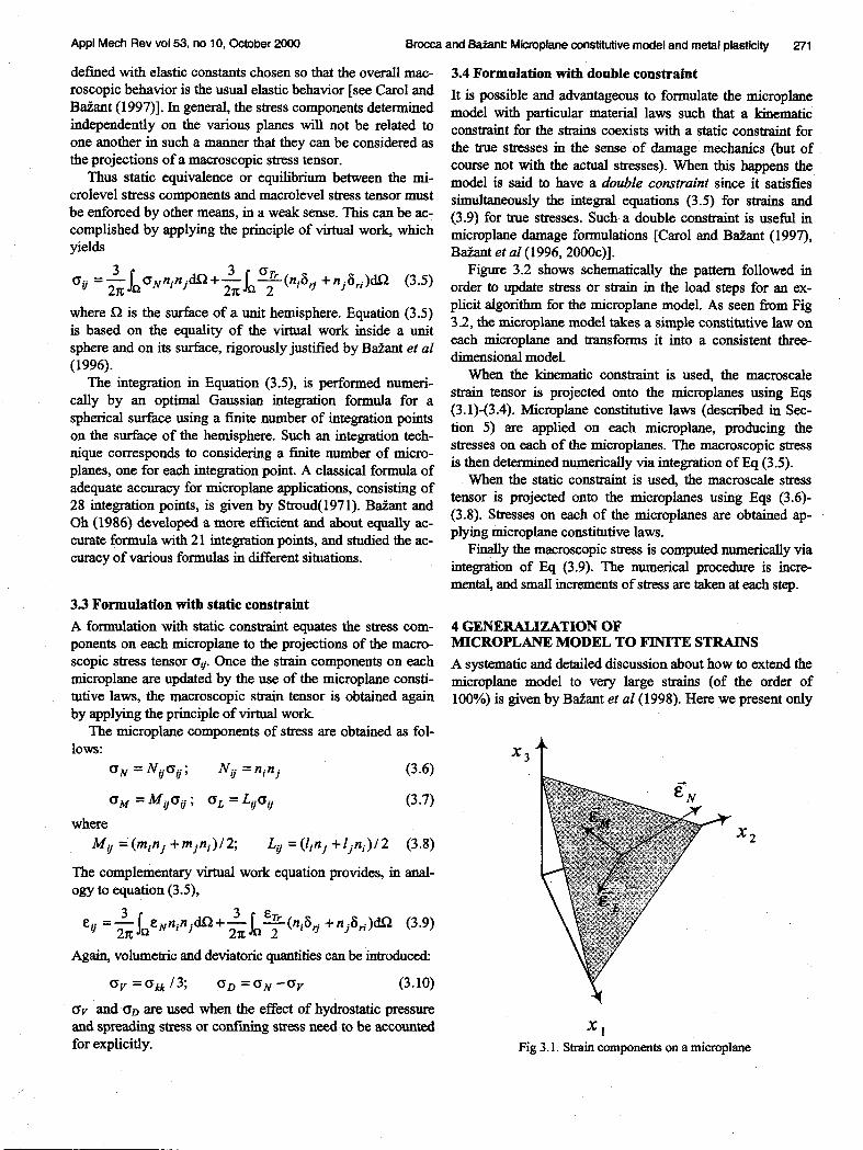

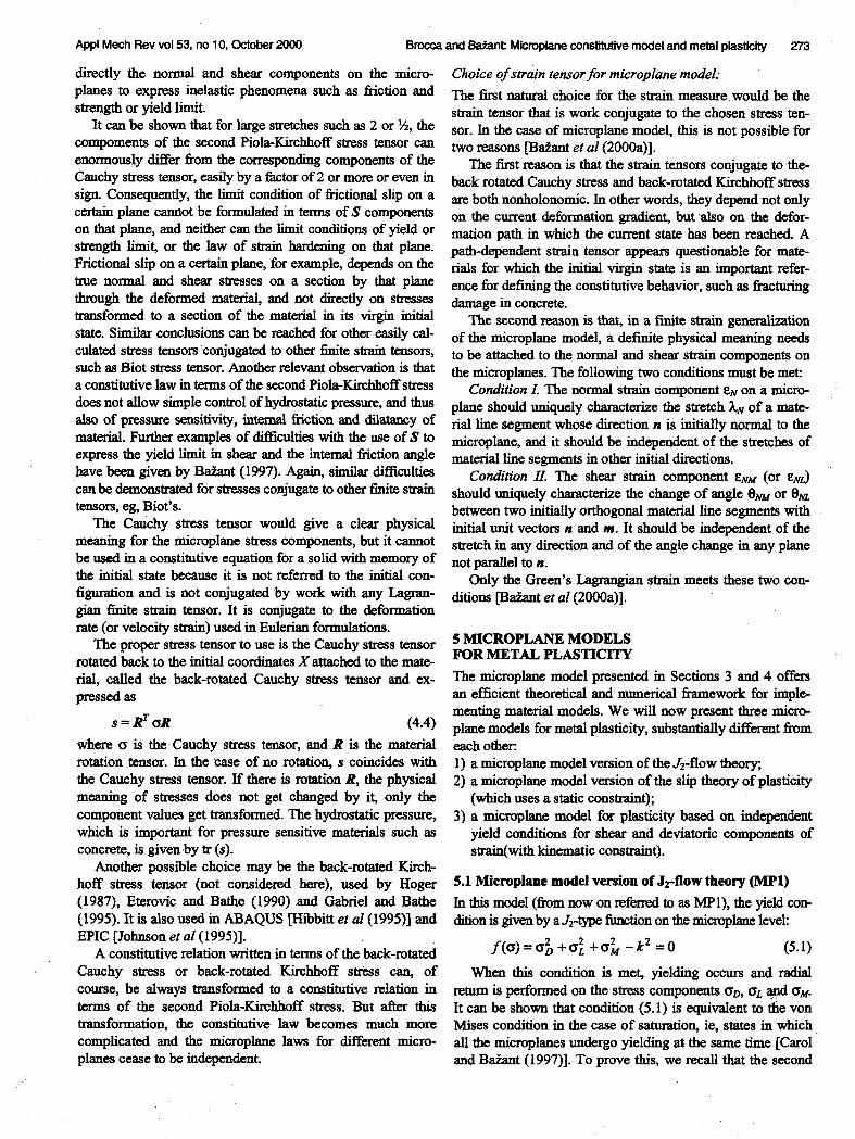
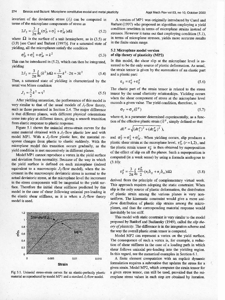


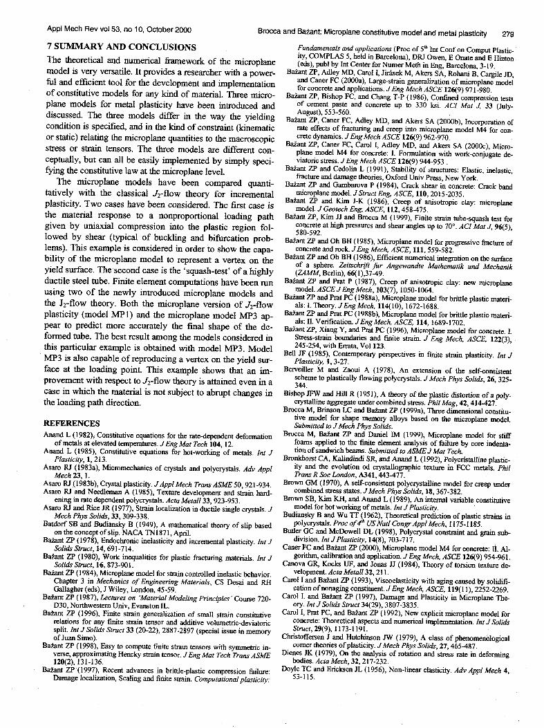
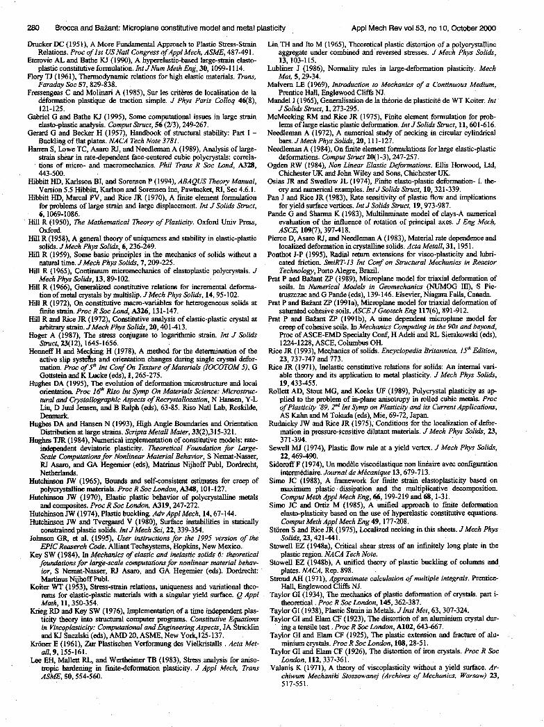

![Computational Materials Sciencepurl.tue.nl/711796496374050.pdf · aggregate of such layered domains. Crystal plasticity [19] is used as a constitutive model for the crystalline phase,](https://static.documents.pub/doc/80x56/5f0f538e7e708231d4439b7f/computational-materials-aggregate-of-such-layered-domains-crystal-plasticity-19.jpg)


![A constitutive model for ferroelectric polycrystalslandis/Landis/Research_files/JMPS1999.pdfferroelectric switching] crystal plasticity theory as developed by Hill "0855# and employed](https://static.documents.pub/doc/80x56/61093046ab062728a77912c3/a-constitutive-model-for-ferroelectric-landislandisresearchfilesjmps1999pdf.jpg)
![Micromechanical modelling of reversible and irreversible ... · aggregate of such layered domains. Crystal plasticity [19] is used as a constitutive model for the crystalline phase,](https://static.documents.pub/doc/80x56/5f0f538f7e708231d4439b83/micromechanical-modelling-of-reversible-and-irreversible-aggregate-of-such-layered.jpg)


