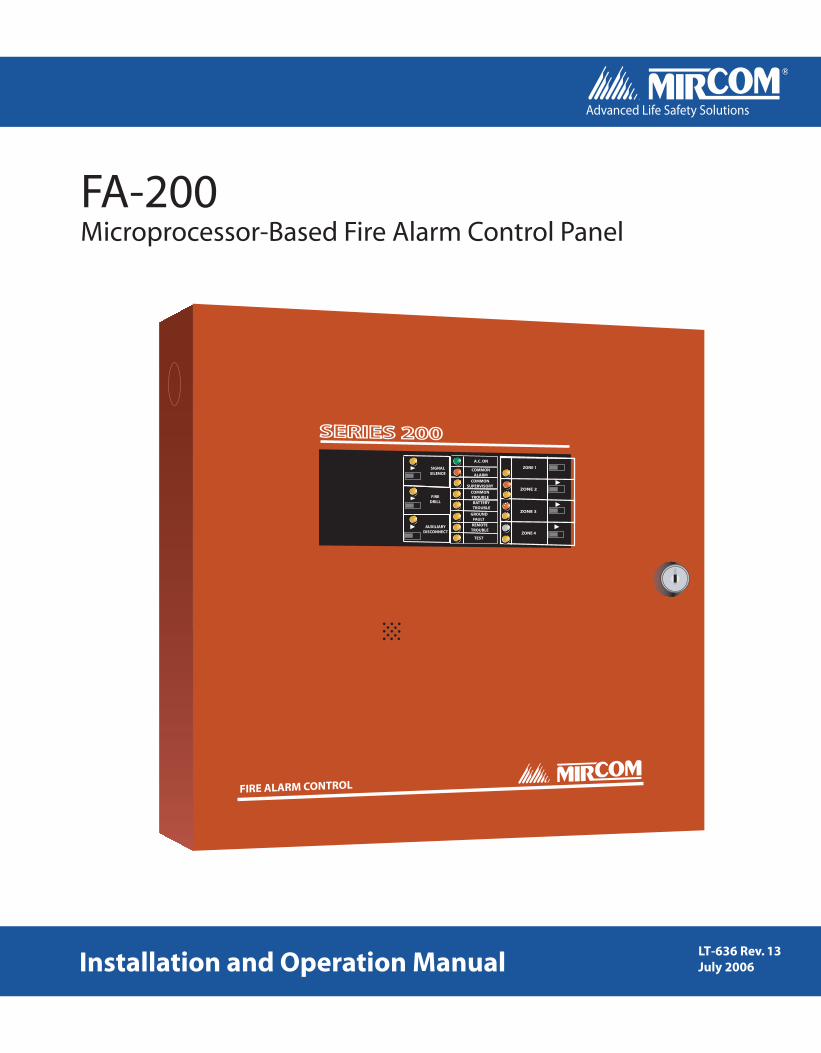
FA-200 Microprocessor-Based Fire Alarm Control Panel LT-636 Rev. 13 July 2006 Installation and Operation Manual Advanced Life Safety Solutions A.C. ON COMMON SUPERVISORY COMMON TROUBLE COMMON ALARM BATTERY TROUBLE GROUND FAULT REMOTE TROUBLE TEST AUXILIARY DISCONNECT FIRE DRILL ZONE 1 ZONE 2 ZONE 3 ZONE 4 SIGNAL SILENCE SERIES 200 FIRE ALARM CONTROL
Transcript
Canada25 Interchange WayVaughan, ON L4K 5W3Tel: 905-660-4655 Fax: 905-660-4113
FA-200Microprocessor-Based Fire Alarm Control Panel
LT-636 Rev. 13July 2006Installation and Operation Manual
Advanced Life Safety Solutions Advanced Life Safety Solutions
A.C. ON
COMMONSUPERVISORY
COMMONTROUBLE
COMMONALARM
BATTERYTROUBLE
GROUNDFAULT
REMOTETROUBLE
TEST
AUXILIARYDISCONNECT
FIREDRILL
ZONE 1
ZONE 2
ZONE 3
ZONE 4
SIGNALSILENCE
SERIES 200
FIRE ALARM CONTROL
U.S.A.60 Industrial ParkwayCheektowaga, NY 14227Tel: 1-888-660-4655 Fax: 1-888-660-4113
FA-200 Series Installation and Operation Manual
i
Contents
List of Figures and Tables................................................................................................................................ iiiIntroduction ....................................................................................................................................................... 1
About this Manual .......................................................................................................................................... 1About the FA-200........................................................................................................................................... 1Overall Features: ........................................................................................................................................... 1Technical Support .......................................................................................................................................... 1
System Configuration....................................................................................................................................... 28Main Fire Alarm Board ................................................................................................................................... 28DM-204 Module ............................................................................................................................................. 30
Walk Test Operation ......................................................................................................................................... 32Appendix A: Compatible Devices.................................................................................................................... 33
Underwriter’s Labs Canada (ULC) Canadian: Two-wire Smoke Detector Control Panel Compatibility........ 33Underwriter’s Labs Inc. (UL) United States: Two-Wire Smoke Detector Control Panel Compatibility .......... 34Underwriter’s Laboratories Inc. (UL) United States: Four-Wire Smoke Detector Control Panel Compatibility 36Underwriter’s Laboratories Inc. (UL) United States: Signalling Device Control Panel Compatibility ............. 36
Appendix C: Module Specifications And Features ....................................................................................... 38FA-201 Fire Alarm Control Panel ................................................................................................................... 38FA-202 Fire Alarm Control Panel ................................................................................................................... 38FA-204 Fire Alarm Control Panel ................................................................................................................... 39Polarity Reversal and City Tie Module (PR-100) ........................................................................................... 39RM-204 / RM-208 Relay Module.................................................................................................................... 39FA-204E Fire Alarm Control Panel................................................................................................................. 39DM-204 Zone Adder Module.......................................................................................................................... 40
Appendix D: Power Supply & Battery Calculations ....................................................................................... 41Warranty............................................................................................................................................................. 43
FA-200 Series Installation and Operation Manual
iii
List of Figures and Tables
FiguresFigure 1: FA-201, 202, and 204 Enclosure Installation and Dimensions .................................. 5Figure 2: FA-204 E Enclosure Installation and Dimensions ...................................................... 6Figure 3: FA-201, 202, and 204 Module Mounting Locations ................................................... 7Figure 4: FA-204E Module Mounting Locations ........................................................................ 8Figure 5: Main Fire Alarm Module ............................................................................................. 9Figure 7: RM-204 or RM-208 Relay Adder Module................................................................... 10Figure 8: DACT-100A Dialer Module......................................................................................... 11Figure 9: PR-100 Polarity Reversal and City Tie Module.......................................................... 11Figure 10: General Field Wiring Considerations ....................................................................... 12Figure 11A: Main Fire Alarm Module Terminal Connections..................................................... 13Figure 11B: Main Fire Alarm Module Terminal Connections (cont’d)........................................ 14Figure 12: DM-204 Zone Adder Module Terminal Connections................................................ 15Figure 13: Relay Module (RM-204 or RM-208) Terminal Connections ..................................... 16Figure 14: DACT-100A Wiring Diagram.................................................................................... 17Figure 15: PR-100 Polarity Reversal and City Tie Module Terminal Connections.................... 18Figure 16: Power Supply Connections ...................................................................................... 19Figure 17: Indicators and Control Location ............................................................................... 22Figure 18: Evacuation Codes .................................................................................................... 27
TablesTable 1: Wiring Table for Initiating Circuits................................................................................ 20Table 2: Wiring Table for Indicating Circuits.............................................................................. 20Table 3: Configuration DIP Switch Functions on Main Fire Alarm Board.................................. 29Table 4: Configuration DIP Switch Functions on DM-204 Module ............................................ 31
List of Figures and Tables
iv
FA-200 Series Installation and Operation Manual
1
Introduction
About this ManualThis installation and operation manual provides information on installing and operating the FA-200 Microprocessor-Based Fire Alarm Control Panel.
About the FA-200Mircom's FA-200 Fire Alarm Control Panels provide 1, 2, 4, or 8 supervised Class B (ULI Style B) Initiating Circuits, or 1, 2, 4 supervised Class A (ULI Style D) Initiating Circuits, and 2 or 4 supervised Class A or B (ULI Style Z or Y) Indicating Circuits. All Circuits are supervised for opens and ground faults, and Indicating Circuits for shorts. Optional Modules include a DM-204 Zone Adder (required for full capacity in the FA-204E only), a DACT-100A Dialler or a PR-100 Polarity Reversal & City Tie Module, and RM-204 or RM-208 Relay Modules. The two enclosures are flush or surface mountable, and can be used for retrofits and on new installations.
Overall Features:• The small enclosure versions, FA-201, FA-202, & FA-204, have 1, 2, 4 Class B (Style B) initiating circuits
respectively. The FA-202 & FA-204 may be configured as 1 or 2 Class A (Style D) Circuits respectively. These also have 2 Power Limited Class A/B (Style Z/Y) indicating circuits with individual trouble indicators.
• The large enclosure version, FA-204E, has four Class B (Style B) initiating circuits which may be configured as two Class A (Style D) circuits respectively. It also has two power limited Class A/B (Style Z/Y) indicating circuits with individual trouble indicators. With a DM-204 Zone Adder Module, an extra four Class B (2 Class A) initiating circuits, and two Class A/B indicating circuits are added.
• Each initiating circuit is configurable as a normal or verified alarm. In addition, on a Class B FA-204 or fa-204e, Initiating Circuit three may be a Waterflow Zone (as may Initiating Circuit 7 if a DM-204 is installed), and initiating circuit four may be a latched or non-latched supervisory zone (as may initiating circuit eight if a DM-204 is installed). On a Class A FA-204E with a DM-204, initiating circuit three may be a waterflow zone and initiating circuit four may be a latched or non-latched supervisory zone.
• Indicating circuits can be configured as audible or visual and as silenceable or non-silenceable. Audibles may be steady, temporal code, california code, or march time.
• Initiating circuits may be individually disconnected by a slide-switch.• Configurable signal silence inhibit (disabled or 1 minute), auto signal silence (disabled or 5, 10, 20 minutes),
and one-man walk test.• Subsequent alarm, supervisory, and trouble operation.• Four-wire resettable smoke power supply (200 mA max.).• Auxiliary relay contacts for common alarm and common supervisory (disconnectable), and a common trouble
relay. If no Supervisory zones are configured then the common supervisory relay can be used as an extra common alarm relay.
• Interface for an RTI Remote Trouble Indicator.• RS-485 Interface for 1 to 3 of RAM-208 Remote Multiplex Annunciators on FA-204 & FA-204E.• The FA-201, FA-202, FA-204 may use one of optional DACT-100A (Dialler), PR-100 (City Tie), RM-204 or RM-
208 Relay Modules.• The FA-204E may use one of optional DACT-100A (Dialler), PR-100 (City Tie), and one of
RM-204 or RM-208 Relay Modules.• Slide Switch controls and LED Common indicators.• Easy configuration via DIP switches.• Extensive transient protection.
Technical SupportFor all technical support inquiries, please contact Mircom’s Technical Support Department between 8 A.M. and 5 P.M. (EDT) Monday through Friday, excluding holidays.
Local Phone: 905-695-3535 Toll-Free Phone: 1-888-449-3535
Local Fax: 905-660-4113 Toll-Free Fax: 1-888-660-4113
Document Conventions
2
Document Conventions
Circuits and ZonesThe term circuits refers to an actual electrical interface, initiating (detection), indicating (signal), or relay.
The term zone is a logical concept for a fire alarm protected area, and will consist of at least one circuit.
Often the terms zone and circuit are used interchangeably, but in this manual the term circuit is used.
Wiring StylesInitiating circuits are configured by default as Class B (Style B). They may be globally (all or none) configured as Class A (Style D) as described in System Configuration on page 28. This operation uses odd and even pairs of two-wire Class B (Style B) circuits to make one four-wire Class A (Style D) circuit, thus cutting in half the number of available initiating circuits.
Indicating circuits may be individually wired as Class A (Style Z) or Class B (Style Y) without affecting the number of circuits available (see Field Wiring on page 12).
FA-200 Series Installation and Operation Manual
3
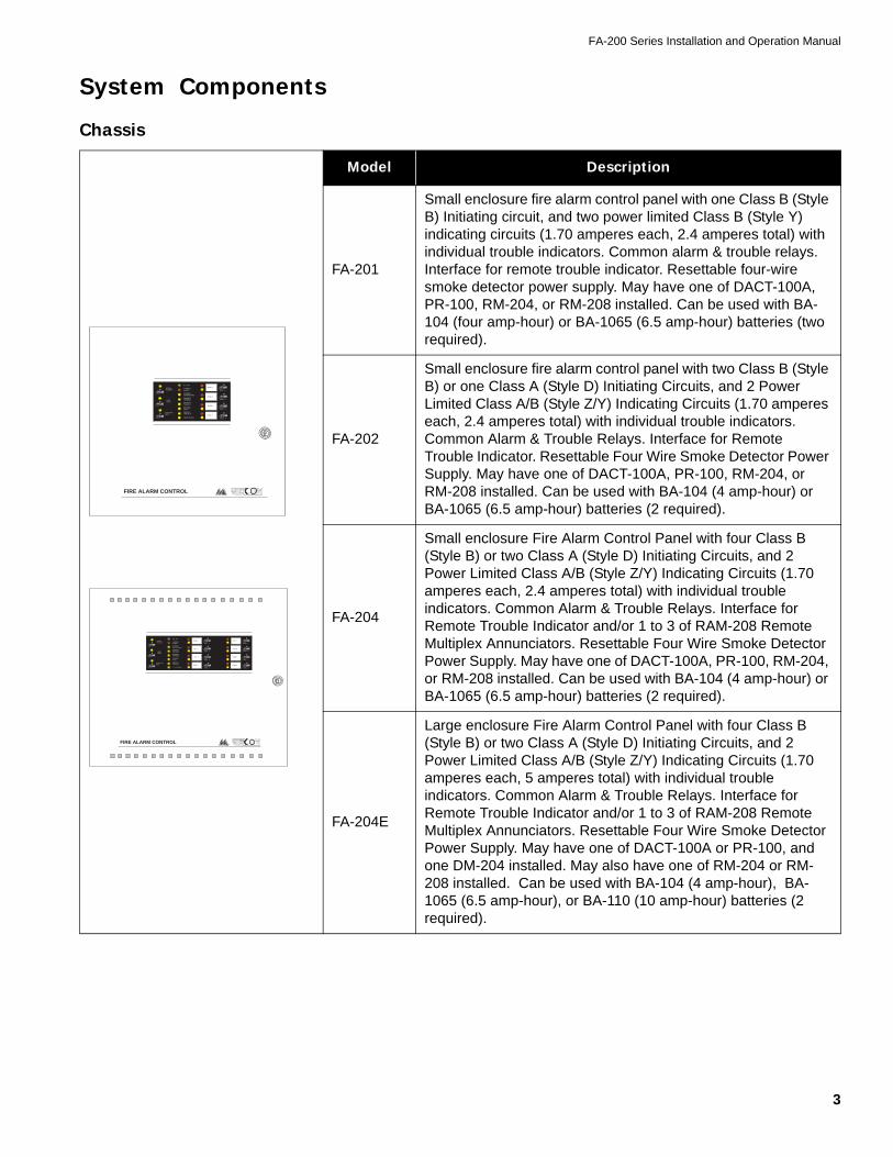
System Components
Chassis
Model Description
FA-201
Small enclosure fire alarm control panel with one Class B (Style B) Initiating circuit, and two power limited Class B (Style Y) indicating circuits (1.70 amperes each, 2.4 amperes total) with individual trouble indicators. Common alarm & trouble relays. Interface for remote trouble indicator. Resettable four-wire smoke detector power supply. May have one of DACT-100A, PR-100, RM-204, or RM-208 installed. Can be used with BA-104 (four amp-hour) or BA-1065 (6.5 amp-hour) batteries (two required).
FA-202
Small enclosure fire alarm control panel with two Class B (Style B) or one Class A (Style D) Initiating Circuits, and 2 Power Limited Class A/B (Style Z/Y) Indicating Circuits (1.70 amperes each, 2.4 amperes total) with individual trouble indicators. Common Alarm & Trouble Relays. Interface for Remote Trouble Indicator. Resettable Four Wire Smoke Detector Power Supply. May have one of DACT-100A, PR-100, RM-204, or RM-208 installed. Can be used with BA-104 (4 amp-hour) or BA-1065 (6.5 amp-hour) batteries (2 required).
FA-204
Small enclosure Fire Alarm Control Panel with four Class B (Style B) or two Class A (Style D) Initiating Circuits, and 2 Power Limited Class A/B (Style Z/Y) Indicating Circuits (1.70 amperes each, 2.4 amperes total) with individual trouble indicators. Common Alarm & Trouble Relays. Interface for Remote Trouble Indicator and/or 1 to 3 of RAM-208 Remote Multiplex Annunciators. Resettable Four Wire Smoke Detector Power Supply. May have one of DACT-100A, PR-100, RM-204, or RM-208 installed. Can be used with BA-104 (4 amp-hour) or BA-1065 (6.5 amp-hour) batteries (2 required).
FA-204E
Large enclosure Fire Alarm Control Panel with four Class B (Style B) or two Class A (Style D) Initiating Circuits, and 2 Power Limited Class A/B (Style Z/Y) Indicating Circuits (1.70 amperes each, 5 amperes total) with individual trouble indicators. Common Alarm & Trouble Relays. Interface for Remote Trouble Indicator and/or 1 to 3 of RAM-208 Remote Multiplex Annunciators. Resettable Four Wire Smoke Detector Power Supply. May have one of DACT-100A or PR-100, and one DM-204 installed. May also have one of RM-204 or RM-208 installed. Can be used with BA-104 (4 amp-hour), BA-1065 (6.5 amp-hour), or BA-110 (10 amp-hour) batteries (2 required).
FIRE ALARM CONTROL
�FIREDRILL�
SIGNALSILENCE
�AUXILIARYDISC.
A.C. ON
COMMONALARM
COMMONSUPERVISORY
COMMONTROUBLE
BATTERYTROUBLE
GROUNDFAULT
REMOTETROUBLE
TEST/CONFIG.
�DISC. 1
ZONE 1
ZONE 2
ZONE 3
ZONE 4
�DISC. 2�DISC. 3
�DISC. 4
��DISC. 5
ZONE 5
ZONE 6
ZONE 7
ZONE 8
��DISC. 6��DISC. 7
��DISC. 8
FIRE ALARM CONTROL
�FIREDRILL
�SIGNALSILENCE
�AUXILIARYDISC.
A.C. ON
COMMONALARM
COMMONSUPERVISORY
COMMONTROUBLE
BATTERYTROUBLE
GROUNDFAULT
REMOTETROUBLE
TEST/CONFIG.
�DISC. 1
ZONE 1
ZONE 2
ZONE 3
ZONE 4��
DISC. 2
�DISC. 3
�DISC. 4
Document Conventions
4
Circuit Adder Modules
Auxiliary Models
These fire alarm control panels are normally provided with a beige enclosure. The FA-201U, FA-202U, FA-204U, and FA-204EU models have red enclosures.
FA-200 Accessories
Models Description
DM-204
Zone Adder Module for the FA-204E. Brings the total capacity to eight Class B (Style B) or four Class A (Style D) Initiating Circuits, and 4 Power Limited Class A/B (Style Z/Y) Indicating Circuits (up to 1.7 amperes each, 5 amperes total).
RM-208Relay Adder Module for the FA-204 or FA-204E. Adds eight configurable Form-C Relays rated 1A, 28 VDC.
RM-204Relay Adder Module for the FA-204 or FA-204E. Adds four configurable Form-C Relays rated 1A, 28 VDC.
Model Description
PR-100 Polarity Reversal and City Tie Module
DACT-100A Digital Communicator / Dialler Module.
Model Description
RAM-208 Eight-Zone Remote Annunciator (ULC and ULI approved)
RTI-1 Remote Trouble Indicator (ULC and ULI approved)
BC-160 External Battery Cabinet (ULC and ULI approved)
FA-200 Series Installation and Operation Manual
5
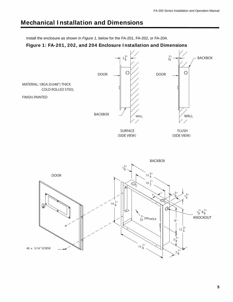
Mechanical Installation and Dimensions
Install the enclosure as shown in Figure 1, below for the FA-201, FA-202, or FA-204.
Figure 1: FA-201, 202, and 204 Enclosure Installation and Dimensions
DOOR
BACKBOXWALL
(SIDE VIEW)SURFACE
DOOR
83 "3-
BACKBOX
DIA.
WALL
(SIDE VIEW)FLUSH
BACKBOX
DOOR
-165"
13 43- "
"-581
1- "210
7- "32 HOLE
12 43- "
87- "
8 "
-15 81"
-81"14
1-83 "
-
3
31 "4
1"
#6 x 5/16" SCREW
KNOCKOUT
-87"&"18-
1
158-
"
FINISH: PAINTED
MATERIAL: 18GA (0.048") THICKCOLD ROLLED STEEL
Mechanical Installation and Dimensions
6
Figure 2: FA-204 E Enclosure Installation and Dimensions
FINISH: PAINTED
DOOR 16GA (0.059") THICKCOLD ROLLED STEEL
DOOR
BACKBOX
(SIDE VIEW)SURFACE
DOOR
45 "1-
BACKBOX
(SIDE VIEW)FLUSH
BACKBOX
DOOR
-165"
WALL WALL
32"-7 DIA.
HOLE
"7815 -
16 "516-
14-3"
11 "
"-1214
1"
"5
""-431
211-
"-7814
1-81 " & "78-
KNOCKOUT-12 21"
83-1 "
2 "
83"4 -
2 "
#6 x 5/16" SCREW
MATERIAL: BACKBOX 18GA (0.048") THICK
FA-200 Series Installation and Operation Manual
7
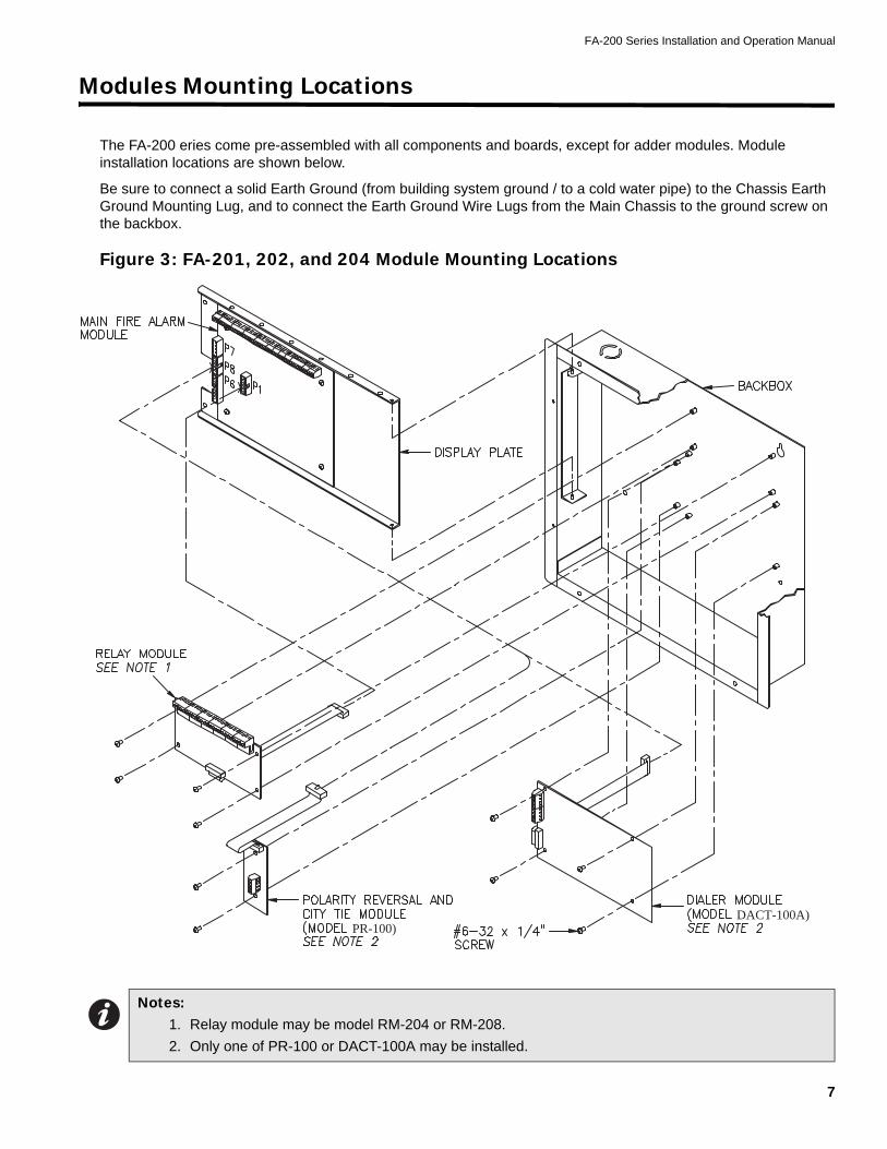
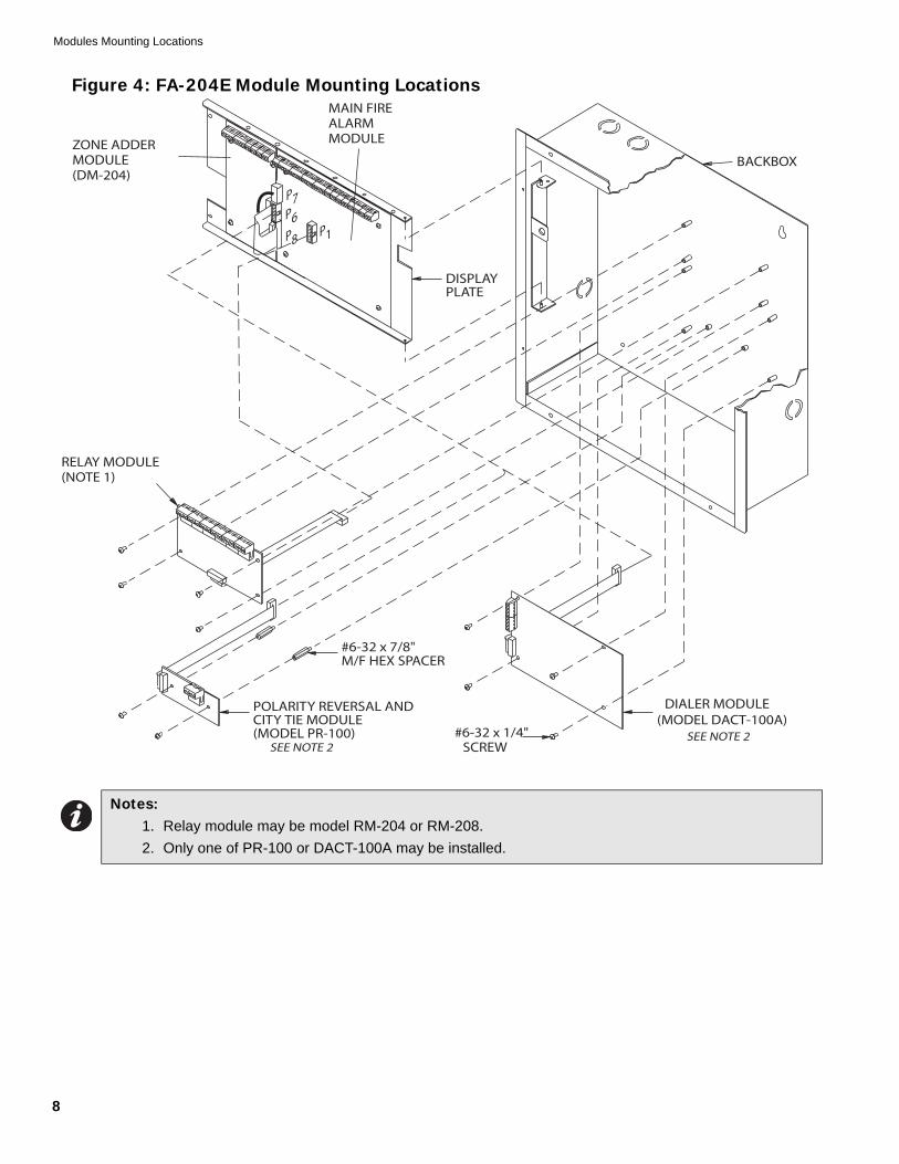
Modules Mounting Locations
The FA-200 eries come pre-assembled with all components and boards, except for adder modules. Module installation locations are shown below.
Be sure to connect a solid Earth Ground (from building system ground / to a cold water pipe) to the Chassis Earth Ground Mounting Lug, and to connect the Earth Ground Wire Lugs from the Main Chassis to the ground screw on the backbox.
Figure 3: FA-201, 202, and 204 Module Mounting Locations
Notes: 1. Relay module may be model RM-204 or RM-208.2. Only one of PR-100 or DACT-100A may be installed.
PR-100)DACT-100A)
Modules Mounting Locations
8
Figure 4: FA-204E Module Mounting Locations
Notes: 1. Relay module may be model RM-204 or RM-208.2. Only one of PR-100 or DACT-100A may be installed.
P8
P7
SEE NOTE 2(MODEL DACT-100A)
DIALER MODULE
SEE NOTE 2(MODEL PR-100)
POLARITY REVERSAL ANDCITY TIE MODULE
M/F HEX SPACER#6-32 x 7/8"
SCREW#6-32 x 1/4"
DISPLAYPLATE
BACKBOXZONE ADDERMODULE(DM-204)
MAIN FIREALARMMODULE
RELAY MODULE(NOTE 1)
P1
P6
FA-200 Series Installation and Operation Manual
9
Module Settings
Main Fire Alarm ModuleClass A / B Selection
On the FA-202, FA-204 and FA-204E only, JW1 & JW2 are connected from 1 to 2 for initiating circuit Class B (Style B) operation, and from 2 to 3 for Class A (Style D) operation. These are not present on the FA-201, and only JW2 is present on the FA-202.
Zone Adder Module: On an FA-204E only, remove the jumper on JW4 if a DM-204 Zone Adder Module is installed. The zone adder module is plugged into P6 & P7.
Relay Module: Remove the jumper on JW3 if an RM-204 or RM-208 Relay Module is installed. The relay module is plugged into P1.
Digital Communicator: Remove the jumper on JW6 if a DACT-100A Digital Communicator is installed. The digital communicator is plugged into P8.
City Tie: Remove the jumper on JW6 if a PR-100 City Tie is installed. The City Tie is plugged into P8.
Battery: Connected to P2(+) & P3(-) via the factory installed cables.
Transformer: Factory wired to P4 & P5, do not disconnect.
JW5: There should be no jumper here; do not use.
SW9,11,13: Configuration DIP switches.
Battery Fuse F1: Replace with 10 amp, 1-1/4" fast acting fuse.
Figure 5: Main Fire Alarm Module
Note: The Class A/B selection affects all initiating circuits, and must be used with the correct Configuration DIP switch setting.
P6
F110 AMPBATTERYFUSE
SW13
123
JW2
P3
23 1
BATT+
P4
P5
P2
BATT-
XMFR
XMFR
JW1P7
P8
JW4
JW5
JW3
JW6SW11 SW9
P1
SUPV RLYCOM-COM+ S
IND2-
IND2-
IND1-IND1-
IND1+IND1+
INI4-INI4+
INI3-INI3+
INI2-INI2+
INI1-INI1+
485-485+ - +
TRBTRL
IND2+
IND2+NO NC
COMALM RLY
NO NCCOM
TBL RLY4 WIRENO NC
COM
Note: Do not plug DACT into P1 on main board. Plug into P8 only when system is powered off.
Note: Do not plug RM-204/208 into P8 on main board. Plug into P1 only when system is powered off.
Module Settings
10
Zone Adder Module (Model DM-204)Figure 6: DM-204 Zone Adder Module
Class A / B Selection: JW2 & JW3 are connected from 1 to 2 for initiating circuit Class B (Style B) operation, and from 2 to 3 for Class A (Style D) operation.
P1 & P2: Connections to P7 & P6 respectively on the main fire alarm board.
SW5,6: Config DIP switches.
Relay Modules (Models RM-204 or RM-208)Figure 7: RM-204 or RM-208 Relay Adder ModuleP1: Connect to P1 on the main fire alarm board.
By the factory setting, the four or eight relays are controlled by initiating circuits 1 to 8 respectively. This is configured by selecting:
• JW1: Initiating Circuit #1 controls Relay #1.
• JW2: Initiating Circuit #2 controls Relay #2.
• JW8: Initiating Circuit #8 controls Relay #8.
Alternately, each relay may be set as a Common Alarm or Common Supervisory Relay by removing the jumper from JW1 to JW1A, etc. These jumpers have two positions to select Alarm or Supervisory each.
• JW1A: Alarm or supervisory control for Relay #1.• JW2A: Alarm or supervisory control for Relay #2.
• JW8A: Alarm or supervisory control for Relay #8.
Finally, there are jumpers JW1.2, JW2.3, up to JW7.8 that allow a relay to have the same control as an adjacent relay. For example, starting with the factory default setting, moving the jumper from JW2 to JW1.2 will make both relays 1 & 2 operate with Initiating Circuit #1.Contact Mircom Technical Support for assistance if required.
Note: The Class A/B selection affects all initiating circuits, and must be used with the correct Configuration DIP switch setting.
P1
FIE
LD
WIR
ING
TE
RM
INA
LS
P2
SW5
2 31
JW3
SW6
2 31
JW2
ALM
K1
RLY1
RM
-20
8/
RM
-20
4R
EL
AY M
OD
UL
E
RLY2 RLY3 RLY4 RLY5 RLY6 RLY7 RLY8
NO
NO
NC
CO
M
NO
NC
CO
M
NO
NC
CO
M
CO
M
NO
NC
CO
M
NO
NC
CO
M
NO
NC
NC
CO
M
NO
NC
CO
M
K2 K3 K4 K5 K6 K7 K8
JW
1A
SUPVJW1 JW2 JW3 JW4
P1
JW5 JW6 JW7 JW8
JW1.2ALM
JW
2A
SUPV
JW2.3ALM
JW
3A
SUPV
JW3.4ALM
JW
4A
SUPV
JW4.5ALM
JW
5A
SUPV
JW5.6ALM
JW
6A
SUPV
JW6.7ALM
JW
7A
SUPV
ALM
JW
8A
SUPV
JW7.8
Note: Do not plug RM-204/208 into P8 on main board. Plug it into P1 only when the system is powered off.
FA-200 Series Installation and Operation Manual
11
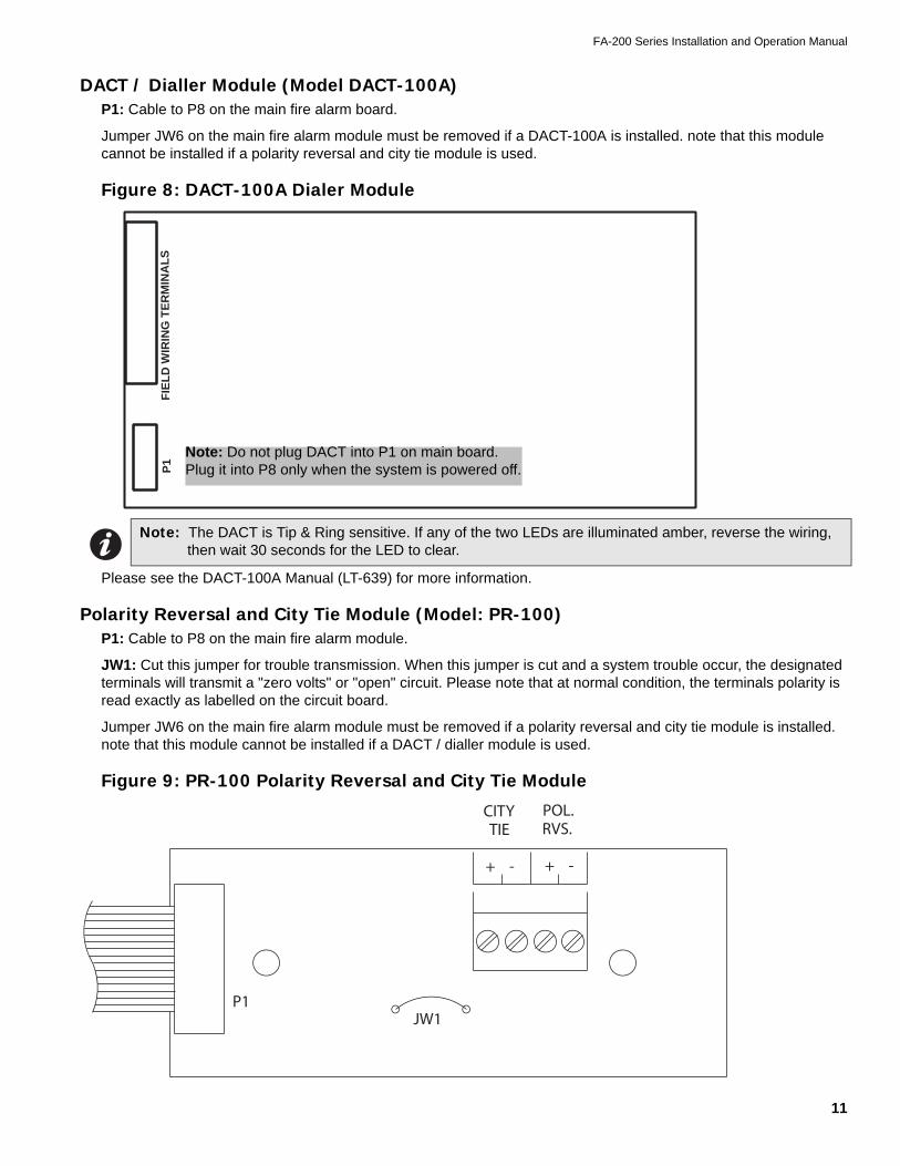
DACT / Dialler Module (Model DACT-100A)P1: Cable to P8 on the main fire alarm board.
Jumper JW6 on the main fire alarm module must be removed if a DACT-100A is installed. note that this module cannot be installed if a polarity reversal and city tie module is used.
Figure 8: DACT-100A Dialer Module
Please see the DACT-100A Manual (LT-639) for more information.
Polarity Reversal and City Tie Module (Model: PR-100)P1: Cable to P8 on the main fire alarm module.
JW1: Cut this jumper for trouble transmission. When this jumper is cut and a system trouble occur, the designated terminals will transmit a "zero volts" or "open" circuit. Please note that at normal condition, the terminals polarity is read exactly as labelled on the circuit board.
Jumper JW6 on the main fire alarm module must be removed if a polarity reversal and city tie module is installed. note that this module cannot be installed if a DACT / dialler module is used.
Figure 9: PR-100 Polarity Reversal and City Tie Module
Note: The DACT is Tip & Ring sensitive. If any of the two LEDs are illuminated amber, reverse the wiring, then wait 30 seconds for the LED to clear.
P1
FIE
LD
WIR
ING
TE
RM
INA
LS
Note: Do not plug DACT into P1 on main board. Plug it into P8 only when the system is powered off.
JW1P1
CITYTIE
+ -
POL.RVS. + -
Field Wiring
12
Field Wiring
General Field Wiring ConsiderationsBecause most of the Field Wiring on the FA-200’s is to the Main Boards on the swinging dead front, it is very important to properly dress the wires so as not to place stress on either their connection to the boards, or running to conduit. The Figure below shows the required wiring techniques.
Figure 10: General Field Wiring Considerations
USE AT LEAST3 WIRE TIES
AS SUPPLIEDTHROUGH HOLESON DEADFRONT
WIRE TIEIN 2 PLACESTO BACK OFENCLOSURE
DRESS WIRES NEARTOP OF ENCLOSURE
CLEAR OF ADDERMODULES
FA-200 Series Installation and Operation Manual
13
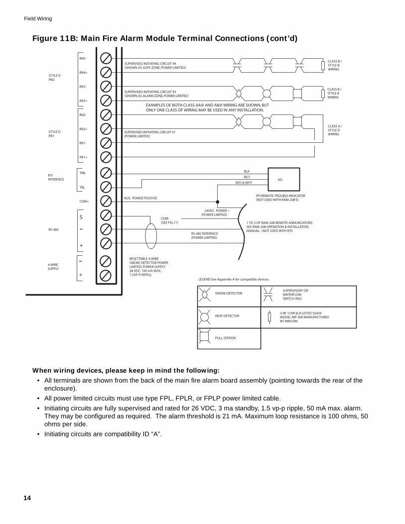
Main Fire Alarm Module Terminal ConnectionsWire devices to terminals as shown in Figure 11 below. See Wiring Tables on page 20 for wiring instructions, Appendix A on page 33 for compatible devices, and Appendix C on page 38 for specifications.
Figure 11A: Main Fire Alarm Module Terminal Connections
When wiring devices, please keep in mind the following:• All terminals are shown from the back of the main fire alarm board assembly (pointing towards the rear of the
enclosure). • All power limited circuits must use type FPL, FPLR, or FPLP power limited cable.• Initiating circuits are fully supervised and rated for 26 VDC, 3 ma standby, 1.5 vp-p ripple, 50 mA max. alarm.
They may be configured as required. The alarm threshold is 21 mA. Maximum loop resistance is 100 ohms, 50 ohms per side.
• Indicating circuits are fully supervised and rated for 24 VDC unfiltered 1.7 amp max. each They must be wired as shown in the wiring tables on page 20.
• On the FA-204 & FA-204E, the auxiliary common supervisory relay contacts will act as a second set of common alarm contacts if there are no initiating circuits set as supervisory.
• Initiating circuits must be all either Style B or D. If Style D is selected, cut the number of circuits in half.
ATTENTION: Do not exceed power supply ratings:•FA-201, FA-202, FA-204, total current for indicating circuits is 2.4 A max.•FA-204E, total current for indicating circuits is 5 A max.
AUX. POWER NEGATIVE FORREMOTE ANNUNCIATORS
NO
NC
COM
TROUBLERELAY
NO
NC
COM
SUPV.RELAY
NO
NC
ALARMRELAY
MUST BECONNECTED TO ALISTED POWERLIMITED SOURCEOF SUPPLY
Figure 11B: Main Fire Alarm Module Terminal Connections (cont’d)
When wiring devices, please keep in mind the following:• All terminals are shown from the back of the main fire alarm board assembly (pointing towards the rear of the
enclosure). • All power limited circuits must use type FPL, FPLR, or FPLP power limited cable.• Initiating circuits are fully supervised and rated for 26 VDC, 3 ma standby, 1.5 vp-p ripple, 50 mA max. alarm.
They may be configured as required. The alarm threshold is 21 mA. Maximum loop resistance is 100 ohms, 50 ohms per side.
1 TO 3 OF RAM-208 REMOTE ANNUNCIATORSSEE RAM-208 OPERATION & INSTALLATIONMANUAL. (NOT USED WITH RTI)
24VDC POWER +(POWER LIMITED) -
-+
4-WIRESUPPLY
INI1+
INI1-
INI2+
INI2-
INI3+
INI3-
INI4+
INI4-
STYLE DINI2
STYLE DINI1
CLASS B /STYLE BWIRING
CLASS A /STYLE DWIRING
SUPERVISED INITIATING CIRCUIT #4(SHOWN AS SUPV ZONE, POWER LIMITED)
SUPERVISED INITIATING CIRCUIT #3(SHOWN AS ALARM ZONE, POWER LIMITED)
SUPERVISED INITIATING CIRCUIT #1(POWER LIMITED)
RESETTABLE 4-WIRESMOKE DETECTOR POWERLIMITED, POWER SUPPLY.28 VDC, 100 mA MAX.,1.5VP-P RIPPLE.
COM+
RTI REMOTE TROUBLE INDICATOR(NOT USED WITH RAM-208'S)
TRBRTIINTERFACE
TRL
+
EXAMPLES OF BOTH CLASS AA@ AND AB@ WIRING ARE SHOWN, BUTONLY ONE CLASS OF WIRING MAY BE USED IN ANY INSTALLATION.
CLASS B /STYLE BWIRING
COM-(SEE FIG.11)
BLU
RS-485 INTERFACE(POWER LIMITED)
AUX. POWER POSITIVE
BLK
RED & WHTRTI
FA-200 Series Installation and Operation Manual
15
Zone Adder Module (DM-204) Terminal ConnectionsWire devices to terminals as shown below in Figure 12. See Wiring Tables for on page 20wiring instructions, Appendix A on page 33 for compatible devices, and Appendix "C on page 38 for Module specifications.
Figure 12: DM-204 Zone Adder Module Terminal Connections
Notes: • All terminals are shown from the back of the main fire alarm board assembly (pointing towards the rear
of the enclosure). • All power limited circuits must use type fPL, FPLR, or FPLP power limited cable.• Initiating circuits are fully supervised and rated for 26 VDC, 3 ma standby, 1.5 vp-p ripple, 50 mA max.
alarm. They may be configured as required. The alarm threshold is 21 mA. Maximum loop resistance is 100 ohms, 50 ohms per side.
CLASS A / STYLE D NOTE:INITIATING CIRCUITS MUST BE ALL EITHER STYLE B ORD. IF STYLE D IS SELECTED, THE NUMBER OF CIRCUITSIS CUT IN HALF.
BELL, HORN, OR STROBE
INI5+
INI5-
INI6+
INI6-
INI7+
INI7-
INI8+
INI8-
STYLE DINI4
STYLE DINI3
CLASS B /STYLE BWIRING
CLASS A /STYLE DWIRING
SUPERVISED INITIATING CIRCUIT #8(SHOWN AS SUPV ZONE, POWER LIMITED)
SUPERVISED INITIATING CIRCUIT #7(SHOWN AS ALARM ZONE, POWER LIMITED)
SUPERVISED INITIATING CIRCUIT #3(POWER LIMITED)
IND4+ (Z)
IND4- (Z)
IND4-(Y/Z)
SUPERVISED INDICATING CIRCUIT #4(POWER LIMITED)
IND3+ (Z)
CLASS A /STYLE ZWIRING
IND3- (Y/Z)
IND3+ (Y/Z)
IND4+ (Y/Z)
IND3- (Z)
CLASS B /STYLE YWIRING
SUPERVISED INDICATING CIRCUIT #3(POWER LIMITED)
CLASS B /STYLE BWIRING
EXAMPLES OF BOTH CLASS AA@ AND AB@ WIRING ARE SHOWN, BUTONLY ONE CLASS OF WIRING MAY BE USED IN ANY INSTALLATION.
EXAMPLES OF BOTH CLASS AA@ AND AB@ WIRING ARE SHOWN, BUTONLY ONE CLASS OF WIRING MAY BE USED IN ANY INSTALLATION.
Field Wiring
16
Relay Module (RM-204 or RM-208) Terminal ConnectionsNote that only relays #1 to #4 are present on the RM-204.
Figure 13: Relay Module (RM-204 or RM-208) Terminal Connections
Notes: • All power limited circuits must use type FPL, FPLR, or FPLP power limited cable. Must be connected to a
listed power limited source of supply.
NO
NCRELAY #2
COM
NO
NCRELAY #1
COM
NO
NCRELAY #3
COM
NO
NCRELAY #4
COM
NO
NCRELAY #5
COM
NO
NCRELAY #6
COM
NO
NCRELAY #7
COM
NO
NCRELAY #8
COM
RELAY CONTACTS28 VDC, 1 AMPRESISTIVE LOAD
RELAY CONTACTS28 VDC, 1 AMPRESISTIVE LOAD
RELAY CONTACTS28 VDC, 1 AMPRESISTIVE LOAD
RELAY CONTACTS28 VDC, 1 AMPRESISTIVE LOAD
RELAY CONTACTS28 VDC, 1 AMPRESISTIVE LOAD
RELAY CONTACTS28 VDC, 1 AMPRESISTIVE LOAD
RELAY CONTACTS28 VDC, 1 AMPRESISTIVE LOAD
RELAY CONTACTS28 VDC, 1 AMPRESISTIVE LOAD
FA-200 Series Installation and Operation Manual
17
DACT / Dialler Module (DACT-100A) Terminal ConnectionsThe following diagram shows the wiring connection for the DACT-100A, refer to the Manual for more details.
Wire the two telephone lines devices to terminals as shown in Figure 14 below.
Line 1 Input (Tip/Ring): To the first Telephone Line via the required RJ31X Connector.Line 1 Output (Tip/Ring): To an optional Premise Telephone on the first Telephone Line via the required RJ31X Connector.Line 2 Input (Tip/Ring): To the second Telephone Line via the required RJ31X Connector.Line 3 Output (Tip/Ring): To an optional Premise Telephone on the second Telephone Line via the required RJ31X Connector.Note that most AHJs do not allow the connection of premise telephones. See Wiring Tables on page 20and Appendix C page 38 for more information.
Figure 14: DACT-100A Wiring Diagram
Note: The terminal blocks are “depluggable” for ease of wiring.
Polarity Reversal and City Tie Module (Model: PR-100) Terminal ConnectionsSee Appendix C on page 38 for module specifications. Wire as shown in Figure 15 below using proper wire gauges.
Note that for use in the USA, the installer must add an Atlantic Scientific (Tel. 407-725-8000) Model #24544 Protective Device, or similar ULI-Listed QVRG Secondary Protector, as shown. For use in Canada, the protective device is still recommended, but the PR-100 may be connected directly to polarity reversal and city tie wiring.
Figure 15: PR-100 Polarity Reversal and City Tie Module Terminal Connections
When wiring devices, please keep in mind the following:• Plug PR-100 ribbon cable (P1) into the main fire alarm module. • Cut Jumper (JW!) on the PR-100 module in order to transmit a trouble condition to the monitoring station.• All circuits are power limited and must use type FPL, FPLR, or FPLP power limited cable.• For polarity reversal operation, short the city tie connection.
Notes:• The terminal blocks are “depluggable” for ease of wiring.• The city tie interface is not power limited.• Use either the PR-100’s City Tie or Reverse Polarity Interface Module--not both.
+
-
USE A SHORTING WIRE WHENTHE CITY TIE IS NOT IN USE.
PRO
TEC
TED
+
-2
1
S
1
2
S
1
1
2
2
S
S
POLARITY REVERSAL24VDC OPEN12VDC AT 3.5 mA8 mA MAX SHORT.
(See Note 4)
PR-100
UN
PRO
TEC
TED
+
+
-
-
DIN RAIL CONNECTIONTO EARTH GROUND.
CITY TIE LOCAL ENERGY24 VDC UNFILTEREDTRIP COIL 14 OHMS,210mA, 5mV RIPPLE.
CONFORMS TO NEMA STANDARDSB3-1969 INTENDED FORCONNECTION TO POLARITYREVERSAL CIRCUIT OF A REMOTESTATION RECEIVING UNIT HAVINGCOMPATIBLE RATINGS.
PROTECTOR
FA-200 Series Installation and Operation Manual
19
Power Supply ConnectionsThe power supply is part of the main fire alarm module and the chassis. The ratings are:
See Appendix C on page 38 for module specifications. Wire as shown in Figure 16 below, using proper wire gauges.
Figure 16: Power Supply Connections
Model Electrical Input Ratings
Power Supply Total Current
Battery Fuse on Main Module
FA-201, FA-202, FA-204
120 V 60Hz 2A / 240V 50 Hz 1A 2.75 A maximum F1: Replace with 10 amp, 1-
1/4" fast acting fuse
FA-204E 120 V 60Hz 2A / 240V 50 Hz 1A 6 A maximum F1: Replace with 10 Amp,
1-1/4" Fast Acting Fuse
ATTENTION: • Do not exceed power supply ratings:• To prevent sparking, connect batteries after the systems main A.C. power is turned on.
GREEN EARTH GROUNDWIRE SOLDERED ONTO MAINFIRE ALARM MODULE PCB.
LL N G
TO DEDICATEDBRANCH CIRCUIT
240V
, 50H
z
120V
, 60H
z
Field Wiring
20
Wiring Tables
Table 1: Wiring Table for Initiating Circuits.
Table 2: Wiring Table for Indicating CircuitsMain board indicating circuits are rated for 1.7 amps each. The SGM-1004(A) indicating circuits are rated for 1.7 amps each.
RS-485 Wiring: See the wiring information for the remote annunciator being used.
4-Wire Smoke Wiring: The maximum allowable current is 0.2 amperes. The maximum allowed voltage drop is 1 volt. Refer to Table 2: WIring for Indicating Circuits above.
Wire Gauge Maximum Wiring Run to Last Device (ELR)
(AWG) ft. m
22 2990 910
20 4760 1450
18 7560 2300
16 12000 3600
14 19000 5800
12 30400 9200
Note: Maximum loop resistance should not exceed 100 Ohms.
Total Signal Load Maximum Wiring Run to Last Device (ELR) Max Loop
Resistance
18AWG 16AWG 14AWG 12AWG 0hms
Amperes ft. m ft. m ft. m ft. m Ohms
0.06 2350 716 3750 1143 6000 1829 8500 2591 30
0.12 1180 360 1850 567 3000 915 4250 1296 15
0.30 470 143 150 229 1200 366 1900 579 6
0.60 235 71 375 114 600 183 850 259 3
0.90 156 47 250 76 400 122 570 174 2
1.20 118 36 185 56 300 91 425 129 1.5
1.50 94 29 150 46 240 73 343 105 1.2
1.7 78 24 125 38 200 61 285 87 1.0
Note: Maximum voltage drop should not exceed 1.8 volts.
FA-200 Series Installation and Operation Manual
21
System Checkout
Before Turning The Power On...1. To prevent sparking, do not connect the batteries. Connect the batteries after powering the system from the
main AC supply.2. Check that all modules are installed in the proper location with the proper connections.3. Check all field (external) wiring for opens, shorts, and ground.4. Check that all interconnection cables are secure, and that all connectors are plugged-in properly.5. Check all jumpers and switches for proper setting.6. Check the AC power wiring for proper connection. 7. Check that the chassis is connected to Earth Ground (cold water pipe).8. Make sure to close the front cover plate before powering the system from main AC supply.
Power-up Procedure1. After completing the System Checkout procedures, power-up the panel. The "AC-ON" green LED should illu-
minate, the “Common Trouble” LED should illuminate, and the buzzer should sound. 2. Press the System Reset button. Since the batteries are not connected, the "Battery Trouble" LED should
illuminate, and the buzzer should sound intermittently, and the Common Trouble LED should flash. 3. Connect the batteries while observing correct polarity; the red wire is positive (+) and black wire is negative (-).
All indicators should extinguish except for normal power "AC-ON" green LED.4. Configure the fire alarm control panel as described in the System Configuration section on page 28.
Troubleshooting
Message Description
Circuit Trouble
Normally when a circuit trouble occurs, its designated trouble indicator will be illuminated, as well as the Common Trouble indicator and Trouble buzzer. To correct the fault, check for open wiring on that particular circuit loop or see if the circuit disconnect switch is in the ON or CLOSED position. Note: disconnecting a circuit will cause a system trouble (off-normal position).
Remote Fail The panel will display a Remote Fail for any failure reported by, or failure to communicate with a remote annunciator, DACT-100A, or PR-100.
Ground Fault The FA-200 panel has a Common Ground Fault Detector. To correct the fault, check for any external wiring touching the chassis or other earth ground connection.
Battery TroubleCheck for the presence of batteries and their conditions. Low voltage (below 20.4V) will cause a battery trouble. If battery trouble condition persists, replace the batteries as soon as possible.
Indicators, Controls, & Operation
22
Indicators, Controls, & Operation
Refer to Figure 17 below for LED Indicators and control switch locations.
Figure 17: Indicators and Control Location
Indicators
BuzzerThe buzzer is activated by any of the following:
If the buzzer turns on in response to a non-latching trouble or supervisory, it will be turned off if the condition causing it goes away and there is no other reason for it to be on.
AC On LEDThe green AC On LED illuminates steadily while the main AC power is within acceptable levels. It turns off when the level falls below the power-fail threshold and the panel switches to standby (battery) power.
Common Alarm LEDThe Common Alarm indicator turns on steady red whenever the panel is in alarm as a result of an alarm on any initiating circuit. Since all alarms are latched until the panel is reset, the indicator will remain on until reset.
FIREDRILL
SIGNALSILENCE
AUXILIARYDISC.
A.C. ON
COMMONALARM
COMMONSUPERVISORYCOMMONTROUBLE
BATTERYTROUBLEGROUNDFAULT
REMOTETROUBLE
TEST
DISC. 1
ZONE 1
ZONE 2
ZONE 3
ZONE 4
DISC. 2
DISC. 3
DISC. 4
DISC. 1
ZONE 5
ZONE 6
ZONE 7
ZONE 8
DISC. 2
DISC. 3
DISC. 4
SIG.ZONE 2TROUBLE
SIG.ZONE 1TROUBLE
SIG.ZONE 4TROUBLE
SIG.ZONE 3TROUBLESYSTEM
RESET
BUZZERSILENCE
LAMPTEST
FA-200 Series Installation and Operation Manual
23
Common Supervisory LED (FA-204 or FA-204E only)The amber Common Supervisory LED illuminates steadily when there is a supervisory alarm in the panel resulting from any latching or non-latching supervisory circuit. The LED turns off if all non-latching supervisory circuits are restored and there are no active latching supervisory circuits. Latching supervisory alarms remain active until the panel is reset.
Common Trouble LEDThe Common Trouble indicator flashes amber (at 20 flashes per minute) when the panel detects any trouble condition. It turns off when all non-latching troubles are cleared.
Remote Trouble LED (FA-204 or FA-204E only)The Remote Failure indicator illuminates amber if the panel detects trouble at a city tie or dialler module, or communication or local trouble with a remote annunciator. It turns off once these conditions return to normal.
Fire Drill LEDThe amber Fire Drill LED illuminates steadily while fire drill is active.
Auxiliary Disconnect LEDThe Auxiliary Disconnect Indicator flashes amber (20 flashes per minute) when the Auxiliary Disconnect switch is activated. It turns off when the switch is activated a second time. When on, the Auxiliary Disconnect LED indicates that common alarm and common supervisory relays, and any RM-204 / RM-208 relays are not activated. The trouble relay is activated. If installed, dialler or polarity reversal and city tie modules are also inactive, causing a trouble condition.
Signal Silence LEDThe amber Signal Silence LED flashes at the trouble flash rate when indication circuits are silenced either by the Signal Silence button or by the Auto Signal Silence timer. It turns off when the signals are re-sounded by a subsequent alarm.
Battery Trouble LEDThe Battery Trouble LED flashes amber at the trouble flash rate when the battery is either low (below 20.4 VDC) or disconnected.
Ground Fault LEDThe Ground Fault LED flashes amber at the trouble flash rate when the Ground Fault Detector detects a ground fault on any field wiring. It turns off when the ground fault is cleared.
Test LEDThe Test LED illuminates amber when the fire alarm panel is in walk test mode.
Circuit Status LEDsThese LEDs indicate the status of initiating circuits. They illuminate
• Alarm: Steady red• Alarm Verification or waterflow retard in progress: fast flashing red (120 flashes per minute)• Pending Alarm: (see Circuit Disconnect Switches on the following page) fast flashing red (120 flashes per
minute)• Supervisory: Steady amber
Circuit Trouble LEDsThese LEDs indicate trouble for initiating and indicating circuits. They flash (20 flashes per minute) for any field wiring fault, or if the circuit has been disconnected.
Indicators, Controls, & Operation
24
Controls
System Reset SwitchThe System Reset momentary switch resets the fire alarm control panel and all circuits:
Signal Silence SwitchActivating the Signal Silence momentary switch when the panel is in alarm turns on the signal silence indicator and deactivates any silenceable indicating circuits. Non-silenceable circuits are unaffected. Signals will re-sound upon any subsequent alarm. This switch does not function during any configured Signal Silence Inhibit timer period. It also does not function if the indicating circuits are active as the result of a fire drill.
Fire Drill SwitchThe Fire Drill momentary switch activates all non-disconnected indicating circuits, but does not transmit any alarms via the dialler, city tie, or common alarm relay, nor are any RM-204 or RM-208 relays activated. The fire drill is cancelled by activating the switch again, or if the panel goes into a real alarm.
Auxiliary Disconnect SwitchActivating the Auxiliary Disconnect momentary switch activates the auxiliary disconnect function. Activating the switch again de-activates the function. When auxiliary disconnect is active, common alarm and common supervisory relays, and any RM-204 / RM-208 relays are not activated. The trouble relay is activated. If installed, dialler or polarity reversal and city tie modules are also inactive, causing a trouble condition.
Lamp Test SwitchActivation of the Lamp Test momentary switch turns all front panel Indicators and the buzzer on.
Buzzer Silence SwitchActivation of the Buzzer Silence momentary switch while the Buzzer is sounding silences the Buzzer. The Buzzer will resound if there is a subsequent event. Switch activation will also silence the buzzer on all attached annunciators.
Circuit Disconnect SwitchesActivation of these non-momentary switches disconnects the respective Initiating Circuit, and causes a Circuit Trouble for that Initiating Circuit while active. If the disconnect switch is turned off (to its normal position) while there is an Alarm condition in that circuit, the respective circuit Status LED will flash at a rate of 120 flashes per minute to indicate a Pending Alarm, for 5 seconds. If the disconnect switch is not turned back on, an Alarm will be processed normally.
•Resets all latching trouble conditions •Resets all initiating circuits
•Resets four-wire smoke supply •Turns off all indicating circuits
•Turns off Signal Silence •Turns off Fire Drill
•Stops and resets all timers •Processes inputs as new events
•Aux Disconnect is not affected
FA-200 Series Installation and Operation Manual
25
OperationAll alarm inputs are treated in a similar manner. Alarm inputs include non-verified or verified alarms, and water-flow alarms. Activation of any alarm input when the panel is not already in alarm cause the following:
• The buzzer sounds steadily• If fire drill is active, it is cancelled• The Common Alarm indicator turns on• the common alarm relay activates if aux disconnect is not active• The Auto Signal Silence timer, if configured, starts• The Signal Silence Inhibit timer, if configured, starts• RM-204 / RM-208 relays are activated as configured, provided that aux disconnect is not active• Signals and strobes are activated
Subsequent Alarms when the panel is already in alarm, cause the following:
• The buzzer sounds steadily • If signals have been silenced as a result of the signal silence button or the auto signal silence timer, signals are
resounded as they were before signal silence, the signal silence indicator is turned off, and the auto signal silence timer, if configured, is restarted
• Signals and strobes are activated
Circuit TypesThe term circuits refers to an actual electrical interface, either initiating (detection) or indicating (signal). The term zone is a logical concept for a fire alarm protected area, and will consist of at least one circuit. Often the terms zone and circuit are used interchangeably, but in this manual the term circuit is used.
Indicators, Controls, & Operation
26
Initiating (Detection) Circuit Types
Circuit Type Description
Non-Verified Alarm
This is a "normal" type of alarm which may have pull stations, smoke detectors, or heat detectors attached. Any activation of these devices will immediately result in an alarm condition in the fire alarm control panel. An alarm condition causes the associated circuit Status LED and the Common Alarm LED to illuminate red.
Verified Alarm
These alarms are verified by a reset and timing procedure, and may have pull stations, smoke detectors, or heat detectors attached. Any activation of pull stations or heat detectors will result in an alarm condition in the fire alarm control panel within four seconds. Smoke detectors will be verified for a real alarm within 60 seconds depending upon the startup time of the smoke detectors being used. If four seconds is too long a response time for pull stations, then they should be wired separately on a non-verified alarm circuit. An alarm condition causes the associated circuit Status LED and the Common Alarm LED to illuminate red.
Water-Flow Alarm
An alarm for water-flow sensors. These alarms are identical to normal non-verified alarms except that any indicating circuits programmed to these circuits (all are by default) are non-silenceable. Also, if water-flow retard operation is enabled, then these circuits are sampled every one second; if ten samples are active within any 15 second interval, the water-flow alarm is confirmed and processed. An alarm condition causes the associated circuit Status LED and the Common Alarm LED to illuminate red. Note: Do not use the retard operation with any external retarding device; maximum retard may not exceed 120 seconds.
Non-Latching Supervisory
These alarms are for supervisory devices. An activation on these circuits will cause the Circuit Status LED and the Common Supervisory LED to illuminate amber. The buzzer will sound continuously. If the circuit activation is removed, the supervisory condition will clear (so long as there are no other supervisory conditions in the system) and the circuit Status LED will extinguish.
Latching Supervisory
These alarms are for supervisory devices. An activation on these circuits will cause the Circuit Status LED and the Common Supervisory LED to illuminate amber. The buzzer will sound continuously. If the circuit activation is removed, the Supervisory condition will not clear.
FA-200 Series Installation and Operation Manual
27
Indicating (Signal) Circuits Types
Evacuation Codes
Single stage codes
Figure 18: Evacuation Codes
Circuit Type Description
Silenceable Signal
For audible devices such as bells and piezo mini-horns that may be silenced either manually or automatically. While sounding, these follow the pattern appropriate for the condition: the configured evacuation code (default is temporal code) during single-stage alarm, or two stage general alarm, or the alert code during a two stage system's alert (first) stage.
Non-Silenceable Signal
For audible devices such as bells and piezo mini-horns that may not be silenced either manually or automatically. While sounding, these follow the pattern appropriate for the condition: the configured evacuation code (default is temporal code) during single-stage alarm, or two-stage general alarm, or the alert code during a two stage system's alert (first) stage.
Silenceable Visual For visual devices such as strobes that use no code pattern (they are continuous).
Non-Silenceable Visual Same as previous, but is non-silenceable.
Continuous On 100% of the time
Temporal Code 3 of 0.5 second on, 0.5 second off then, 1.5 second pause
March Code 0.5 second on, 0.5 second off
California Code 5 seconds on, 10 seconds off
0.5s0.5s
1.5s
0.5s0.5s
5s 10s
CONTINOUS
TEMPORAL CODE
MARCH CODE
CALIFORNIA CODE
0.5s2.5s
ALERT CODE
System Configuration
28
System Configuration
Main Fire Alarm BoardConfiguration of the FA-200 Series is accomplished simply by DIP Switch Settings on the Main Fire Alarm Board. For DIP Switches, 0 = switch “off”, 1 = Switch “on’). The DIP switches are located on the bottom left side of the main fire alarm board.
MAIN FIRE ALARM BOARD
FIELD WIRING TERMINALS
P6
F110 AMPBATTERYFUSE
SW13
123
JW2
P3
23 1
BATT+
P4
P5
P2
BATT-
XMFR
XMFR
JW1
P7
P8
JW4
JW5
JW3
JW6
SW11 SW9
P1
FA-200 Series Installation and Operation Manual
29
Table 3: Configuration DIP Switch Functions on Main Fire Alarm Board
Notes:• After you change any configuration switches, perform a system reset.• Do not use retard operation with any external retarding device; maximum retard may not exceed 120
seconds.
System Configuration
30
When configuring the FA-200 main board, keep in mind the following information:• Only indicating circuit two may be configured for visual devices.• If initiating circuit three is configured as waterflow, the corresponding verified selection becomes a retard
selection.• If initiating circuit four is configured as alarm, the corresponding latching selection has no effect.• If initiating circuit four is configured as supervisory, the corresponding verified selection has no effect.• The selection of Class A/B (Style Z/Y) indicating circuits is only a matter of how they are wired. See connection
information on page 13 .• If Class A (Style D) initiating circuits are selected (FA-202, FA-204, FA-204E only), the appropriate board
jumpers must also be set. Class B initiating circuits one and two combine to create Class A Circuit #1, and Class B initiating circuits three and four combine to create Class A Circuit #2. DIP switches for circuits three and four are ignored except for an FA-204E with a DM-204 Adder Module. LED indicators for circuits three and four are non-functional except for an FA-204E with a DM-204 Adder Module.
DM-204 ModuleOn the DM-204 Zone Adder Module the DIP switches are located on the bottom right-hand corner.
FA-200 Series Installation and Operation Manual
31
Table 4: Configuration DIP Switch Functions on DM-204 Module
When configuring the DM-204, keep in mind the following information:• Only Indicating Circuit #4 may be configured for visual devices.• If Initiating Circuit #7 is configured as waterflow, the corresponding verified selection becomes a retard
selection.• If Initiating Circuit #8 is configured as alarm, the corresponding latching selection has no effect.• If Initiating Circuit #8 is configured as supervisory, the corresponding verified selection has no effect.• The selection of Class A/B (Style Z/Y) indicating circuits is only a matter of how they are wired. See connection
information on page 15.• If Class A (Style D) initiating circuits are selected the appropriate board jumpers must also be set. Class B
initiating circuits 5 and 6 combine to create Class A Circuit #3, and Class B initiating circuits 7 and 8 combine to create Class A Circuit #4. DIP switches for circuits 5 to 8 are ignored, and led indicators for circuits 5 to 8 are non-functional.
Not Used Switch 6, #4 ----------------- -----------------
Initiating Circuit #5Alarm Only
Switch 5, #1 Normal Alarm Verified Alarm
Initiating Circuit #6Alarm Only
Switch 5, #2 Normal Alarm Verified Alarm
Initiating Circuit #7Alarm or Waterflow
Switch 5, #3 Normal Verified Alarm / Retarded Waterflow
Switch 5, #4 Alarm Waterflow
Initiating Circuit #8Alarm or Supervisory
Switch 5, #5 Normal Verified Alarm (no effect on Supv.)
Switch 5, #6 Alarm Supervisory
Switch 5, #7Non-Latching Supervisory
(No effect on Alarm)
Latching Supervisory(No effect on Alarm)
Not Used Switch 5, #8 ----------------- -----------------
Notes:• After you change any configuration switches, perform a system reset.• Do not use retard operation with any external retarding device; maximum retard may not exceed 120
seconds.
Walk Test Operation
32
Walk Test Operation
A walk test allows an installer to verify the Initiating Circuit wiring in a system. To enter walk test, press and hold both the Buzzer Silence and Lamp Test momentary switches for at least one second. You can identify circuits to be tested using the Circuit Disconnect slide switches. Activation of any initiating circuit that has been selected for the walk test will cause the audible indicating circuits to activate briefly for a number of short bursts corresponding to the circuit number. Any subsequent activations on the same initiating circuit will activate the audible indicating circuit only once. If another initiating circuit is activated then the audible indicating circuits will activate for a number of short bursts corresponding to the circuit number of the new zone being walk-tested, and so on.
For example, if Initiating Circuit #3 is first activated, the indication circuits will sound for three bursts. Any subsequent activations of Initiating Circuit #3 will sound for one burst. The initial burst interval denoting the count of the circuit number is one second on followed by 1/2 second off. The subsequent burst interval denoting additional activations on the same initiating circuit is 1/2 second on then off. After the sounding pattern has been sent on the indicating circuits, the initiating circuit is reset and tested again. If it is still active (in alarm) the pattern will be re-sent. Trouble on any initiating circuit when in walk test mode causes all indicating circuits to be activated continuously for five seconds.
Alarm verification and water-flow alarm retard operations are disabled on circuits being walk tested. All circuits not selected for walk-test continue to function normally. The walk test operation is disabled if the fire alarm control panel is in alarm or goes into alarm while walk-test is active. It will also time out after 60 minutes of no activity.
Note: Whether mixing different models of compatible smoke detectors or using the same model on the same circuit, the total standby current of all detectors must not exceed 3 mA.
Make Model / Base Make Model / Base Make Model / Base
Underwriter’s Labs Inc. (UL) United States: Two-Wire Smoke Detector Control Panel Compatibility
Notes: • Whether mixing different models of compatible smoke detectors or using the same model on the same
circuit, total standby current of all detectors must not exceed 3 mA.• The below listed smoke detectors are compatible with initiating circuits having Compatibility Identifier
"A".
Smoke Detector Make Model / Base
Compatibility Identifier Head
/ Base
Rated Standby Current
Smoke Detector Make Model / Base
Compatibility Identifier Head / Base
Rated Standby Current
Hochiki System Sensor (cont’d)
DCD-135/NS6-220 HD-3/HB-72 0.035mA 2400AIT A - N/A 0.12 mA
DCD-135/NS4-220 HD-3/HB-3 0.035mA 2451 / B401B A - A 0.12 mA
DCD-135/HSC-220R HD-3/HB-3 0.035mA 2451 / B406B A - A 0.12 mA
DCD-190/NS6-220 HD-3/HB-3 0.035mA 2451 / DH400 A - N/A 0.12 mA
DCD-190/NS4-220 HD-3/HB-3 0.035mA 2451TH / B406B A - A 0.12 mA
DCD-190/HSC-220R HD-3/HB-3 0.035mA 2451 / B401 A - A 0.12 mA
SIJ-24/NS6-220 HD-3/HB-72 0.040mA 2451TH / B401 A - A 0.12 mA
SIJ-24/NS4-220 HD-3/HB-3 0.040mA 4451HT / B401B A - A 0.12 mA
SIJ-24/HSC-220R HD-3/HB-3 0.040mA 4451HT / B406B A - A 0.12 mA
SLR-24/NS6-220 HD-3/HB-72 0.045mA 4451HT / B401 A - A 0.12 mA
SLR-24/NS4-220 HD-3/HB-3 0.045mA 5451 / B401B A - A 0.12 mA
SLR-24/HSC-220R HD-3/HB-3 0.045mA 5451 / B401 A - A 0.12 mA
SLR-24H/NS6-220 HD-3/HB-3 0.045mA 5451 / B406B A - A 0.12 mA
SLR-24H/NS4-220 HD-3/HB-3 0.045mA
SLR-24H/HSC-220R HD-3/HB-72 0.045mA
SLR-835/NS6-220 HD-3/HB-3 0.045mA Sentrol - ESL
SLR-835/NS6-220 HD-3/HB-3 0.045mA 429C S10A - N/A 0.10 mA
SLR-835/NS4-220 HD-3/HB-3 0.045mA 429CT S10A - N/A 0.10 mA
SLR-835/HSC-220R HD-3/HB-72 0.045mA 429CST S11A - N/A 0.10 mA
The RAM-208 Eight Zone Remote Annunciator mounts in an electrical box. It provides annunciation for the FA-204 or FA-204E’s full complement of 8 Initiating circuits.
For more detailed information see Mircom Document LT-648.
Appendix C: Module Specifications And Features
38
Appendix C: Module Specifications And Features
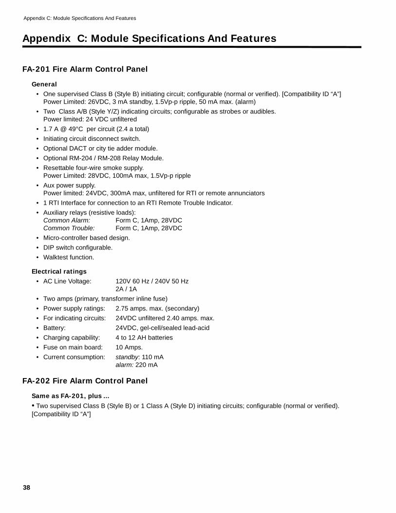
FA-201 Fire Alarm Control Panel
General• One supervised Class B (Style B) initiating circuit; configurable (normal or verified). [Compatibility ID “A”]
Power Limited: 26VDC, 3 mA standby, 1.5Vp-p ripple, 50 mA max. (alarm)• Two Class A/B (Style Y/Z) indicating circuits; configurable as strobes or audibles.
Power limited: 24 VDC unfiltered• 1.7 A @ 49°C per circuit (2.4 a total)• Initiating circuit disconnect switch.• Optional DACT or city tie adder module.• Optional RM-204 / RM-208 Relay Module.• Resettable four-wire smoke supply.
Power Limited: 28VDC, 100mA max, 1.5Vp-p ripple• Aux power supply.
Power limited: 24VDC, 300mA max, unfiltered for RTI or remote annunciators• 1 RTI Interface for connection to an RTI Remote Trouble Indicator.• Auxiliary relays (resistive loads):
Common Alarm: Form C, 1Amp, 28VDCCommon Trouble: Form C, 1Amp, 28VDC
• Micro-controller based design.• DIP switch configurable.• Walktest function.
Electrical ratings• AC Line Voltage: 120V 60 Hz / 240V 50 Hz
2A / 1A• Two amps (primary, transformer inline fuse)• Power supply ratings: 2.75 amps. max. (secondary)• For indicating circuits: 24VDC unfiltered 2.40 amps. max.• Battery: 24VDC, gel-cell/sealed lead-acid• Charging capability: 4 to 12 AH batteries• Fuse on main board: 10 Amps.• Current consumption: standby: 110 mA
alarm: 220 mA
FA-202 Fire Alarm Control Panel
Same as FA-201, plus ...• Two supervised Class B (Style B) or 1 Class A (Style D) initiating circuits; configurable (normal or verified). [Compatibility ID “A”]
FA-200 Series Installation and Operation Manual
39
FA-204 Fire Alarm Control Panel
Same as FA-201, plus ...• Four supervised Class B (Style B) or two Class A ( Style D) Initiating circuits; configurable (normal or verified,
and for Class B there may be one waterflow and one supervisory). [Compatibility ID “A”]• Optional RM-204 or RM-208 Relay Module.• One RS-485 connection for up to 3 RAM-208 Remote Annunciators.• Auxiliary relays: (resistive loads) common alarm, supervisory, trouble
all are Form C, 1 amp, 28VDC• DACT / Dialler Module (DACT-100A)• DACT - “Digital Alarm Communicator Transmitter”• Using Ademco Contact ID and SIA-DCS Protocols.• See Mircom document LT-617 for further info.• Current Consumption: standby: 45 mA
alarm: 120 mA
Polarity Reversal and City Tie Module (PR-100)• Supervised city tie: not power limited• 24VDC unfiltered, 210 mA max., Trip coil: 14 ohms• Polarity reversal: power limited• 24VDC open, 12VDC @ 3.5 mA, 8 mA max. (shorted) • Current consumption: standby: 35 mA
alarm: 300 mA
RM-204 / RM-208 Relay Module• Four or eight relays: Form C, 1A (resistive), 28 VDC per contacts• Each individual relay can be relay per zone, common alarm, common supervisory• Current Consumption: standby: 5 mA
alarm: 160 mA
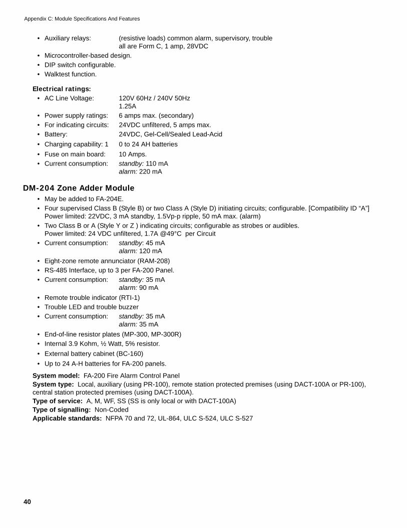
FA-204E Fire Alarm Control Panel
General• Four supervised Style B (Class B) or 2 Style D (Class A) initiating circuits; configurable. [Compatibility ID “A”]
Power limited:26VDC, 3 mA standby, 1.5Vp-p ripple, 50 mA max. (alarm)• Two Class A/B (Style Y/ Z) indicating circuits; configurable as strobes or audibles.
Power limited:24 VDC unfiltered• 1.7 A @ 49°C per circuit (5A total)• One DM-204 Zone Adder Module may be added.• Initiating circuit disconnect switches.• Optional DACT or city tie adder module.• Optional RM-204 / RM-208 Relay Module.• Resettable four-wire smoke supply.
Power limited: 28VDC, 100mA max, 1.5Vp-p ripple• Aux power supply.• Power limited: 24VDC, 300mA max, unfiltered• for RTI or Remote Annunciators• 1 RS-485 connection for up to 3 RAM-208 Remote Annunciators.• 1 RTI interface for connection to an RTI Remote Trouble Indicator.
Appendix C: Module Specifications And Features
40
• Auxiliary relays: (resistive loads) common alarm, supervisory, troubleall are Form C, 1 amp, 28VDC
Electrical ratings:• AC Line Voltage: 120V 60Hz / 240V 50Hz
1.25A• Power supply ratings: 6 amps max. (secondary)• For indicating circuits: 24VDC unfiltered, 5 amps max.• Battery: 24VDC, Gel-Cell/Sealed Lead-Acid• Charging capability: 1 0 to 24 AH batteries• Fuse on main board: 10 Amps.• Current consumption: standby: 110 mA
alarm: 220 mA
DM-204 Zone Adder Module• May be added to FA-204E.• Four supervised Class B (Style B) or two Class A (Style D) initiating circuits; configurable. [Compatibility ID “A”]
Power limited: 22VDC, 3 mA standby, 1.5Vp-p ripple, 50 mA max. (alarm)• Two Class B or A (Style Y or Z ) indicating circuits; configurable as strobes or audibles.
Power limited: 24 VDC unfiltered, 1.7A @49°C per Circuit• Current consumption: standby: 45 mA
alarm: 120 mA• Eight-zone remote annunciator (RAM-208)• RS-485 Interface, up to 3 per FA-200 Panel.• Current consumption: standby: 35 mA
alarm: 90 mA• Remote trouble indicator (RTI-1)• Trouble LED and trouble buzzer• Current consumption: standby: 35 mA
alarm: 35 mA• End-of-line resistor plates (MP-300, MP-300R)• Internal 3.9 Kohm, ½ Watt, 5% resistor.• External battery cabinet (BC-160)• Up to 24 A-H batteries for FA-200 panels.
System model: FA-200 Fire Alarm Control PanelSystem type: Local, auxiliary (using PR-100), remote station protected premises (using DACT-100A or PR-100), central station protected premises (using DACT-100A).Type of service: A, M, WF, SS (SS is only local or with DACT-100A)Type of signalling: Non-CodedApplicable standards: NFPA 70 and 72, UL-864, ULC S-524, ULC S-527
FA-200 Series Installation and Operation Manual
41
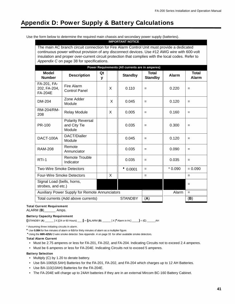
Appendix D: Power Supply & Battery Calculations
Use the form below to determine the required main chassis and secondary power supply (batteries).
Total Current RequirementALARM (B)______ Amps.
Battery Capacity Requirement([STANDBY (A) ______ ] X [(24 or 60 Hours) ___ ]) + ([ALARM (B) ______ ] X [♣Alarm in Hr.] _____) = (C) ______AH
* Assuming three initiating circuits in alarm.♣ Use 0.084 for five minutes of alarm or 0.5 for thirty minutes of alarm as a multiplier figure. ♦Using the MIR-425/U 2-wire smoke detector. See Appendix A on page 33 for other available smoke detectors.
Total Alarm Current• Must be 2.75 amperes or less for FA-201, FA-202, and FA-204. Indicating Circuits not to exceed 2.4 amperes.• Must be 6 amperes or less for FA-204E. Indicating Circuits not to exceed 5 amperes.
Battery Selection• Multiply (C) by 1.20 to derate battery.• Use BA-1065(6.5AH) Batteries for the FA-201, FA-202, and FA-204 which charges up to 12 AH Batteries.• Use BA-110(10AH) Batteries for the FA-204E.• The FA-204E will charge up to 24AH batteries if they are in an external Mircom BC-160 Battery Cabinet.
IMPORTANT NOTICE
The main AC branch circuit connection for Fire Alarm Control Unit must provide a dedicated continuous power without provision of any disconnect devices. Use #12 AWG wire with 600-volt insulation and proper over-current circuit protection that complies with the local codes. Refer to Appendix C on page 38 for specifications.
Mircom Technologies Ltd., manufactured equipment is guaranteed to be free of defects in material and workmanship for a period of one (1) year from the date of original shipment. Mircom will repair or replace, at its option, any equipment which it determines to contain defective material or workmanship. Said equipment must be shipped to Mircom prepaid. Return freight will be prepaid by Mircom. We shall not be responsible to repair or replace equipment which has been repaired by others, abused, improperly installed, altered or otherwise misused or damaged in any way. Unless previously contracted by Mircom, Mircom will assume no responsibility for determining the defective or operative status at the point of installation, and will accept no liability beyond the repair or replacement of the product at our factory authorized service depot.
Canada25 Interchange WayVaughan, ON L4K 5W3
U.S.A.60 Industrial ParkwayCheektowaga, NY 14227
Phone: 1-888-660-4655Fax: 1-888-660-4113
www.mircom.com
Canada25 Interchange WayVaughan, ON L4K 5W3Tel: 905-660-4655 Fax: 905-660-4113