57
Microscopy for Biology Education Practical Experiments for Education in Biology
Microscopyfor Biology EducationPractical Experiments for Education in Biology
2
Part II: Transmitted Light Microscopy in Biology 25
3. Sample Preparation 26
Specimens 27
Overview of Preparation
and Illumination Methods 28
Overview of Important Stainings and Dyes 29
4. Representation of the Microscopic Image 31
Microscopic Drawings 33
5. Selected Experiments 36
Fertilization Experiment
with the Sea Urchin as Example 36
Dry Specimens from Insects 40
Insect Leg Types 42
Onion Cells and Their
Component Parts 44
Chloroplasts in Waterweed 46
Chloroplasts in the Tomato 47
Preparation of Fresh Specimens
of Human and Animal Origin 48
Detection of Intracellular Compo-
nents with Starch as Example 50
Paramecia 51
ContentsPart I: Basics of Microscopy 3
1. The Microscope and How It Works 7
Basics of Microscopy 12
Microscope Types 14
Koehler Illumination in Transmitted Light 15
Dedicated Contrasting Techniques 16
2. Practical Demonstrations of
How a Microscope Works 20
Image Formation in a Microscope 20
Color Correction of Various
Classes of Objectives 20
Cover-Glass Thickness 20
Objective with Correction Collar 20
The Effects of the Aperture 20
Parfocality 21
Alignment for
Koehler Illumination 21
Darkfield Transmitted Light 23
Phase-Contrast Microscopy 23
Phase-Contrast Microscopy:
Adjusting the Phase Ring 23
Oblique Illumination 24
Polarization Contrast 24
Part III: References and Notes 53
6. Sources 54
List of References 54
List of Figures 54
Specimens 54
Recommended Literature 55
Demo 2
Demo 3
Demo 4
Demo 5
Demo 6
Demo 7
Demo 8
Demo 9
Demo 10
Demo 11
Demo 12
Experiment 1
Experiment 2
Experiment 3
Experiment 4
Experiment 5
Experiment 6
Experiment 7
Experiment 8
Experiment 9
Demo 1
Aphid
Part I
Basics of Microscopy
TABLE OF CONTENTS
Part I | Basics of Microscopy
4
Basics of Microscopy
This manual is intended for all trainers of bio-
medical applications in individual instruction and
at schools and universities.
It will provide you with basic information on
microscopy, sample preparation, and practical
instructions for biological experiments.
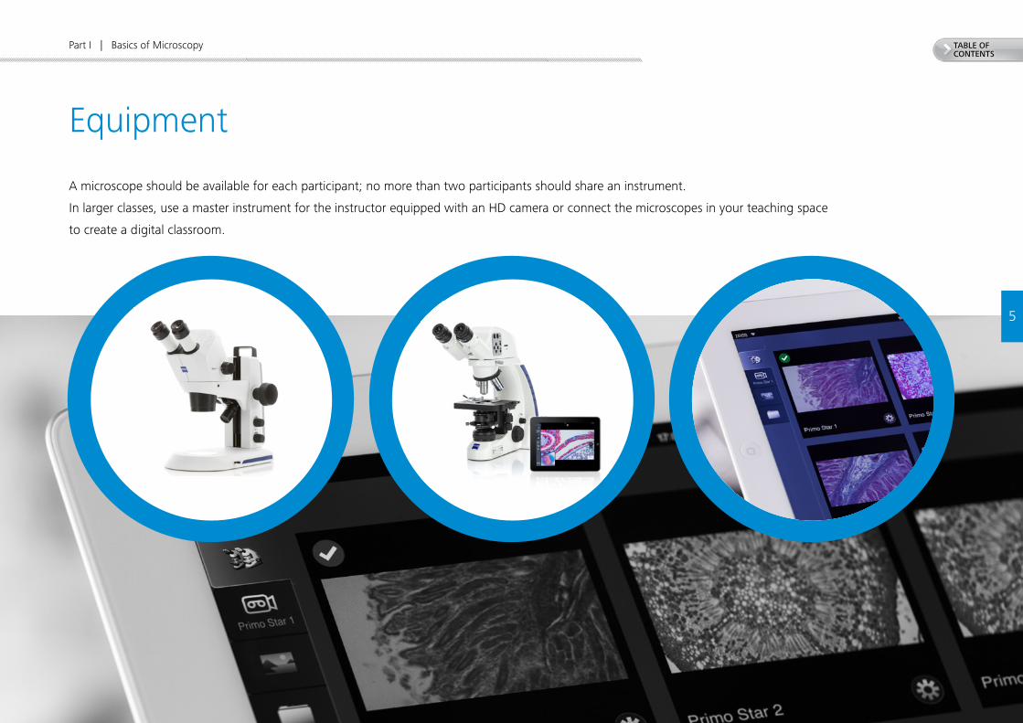
TABLE OF CONTENTS
5
Part I | Basics of Microscopy
Equipment
A microscope should be available for each participant; no more than two participants should share an instrument.
In larger classes, use a master instrument for the instructor equipped with an HD camera or connect the microscopes in your teaching space
to create a digital classroom.
6
TABLE OF CONTENTS
6
Part I | Basics of Microscopy
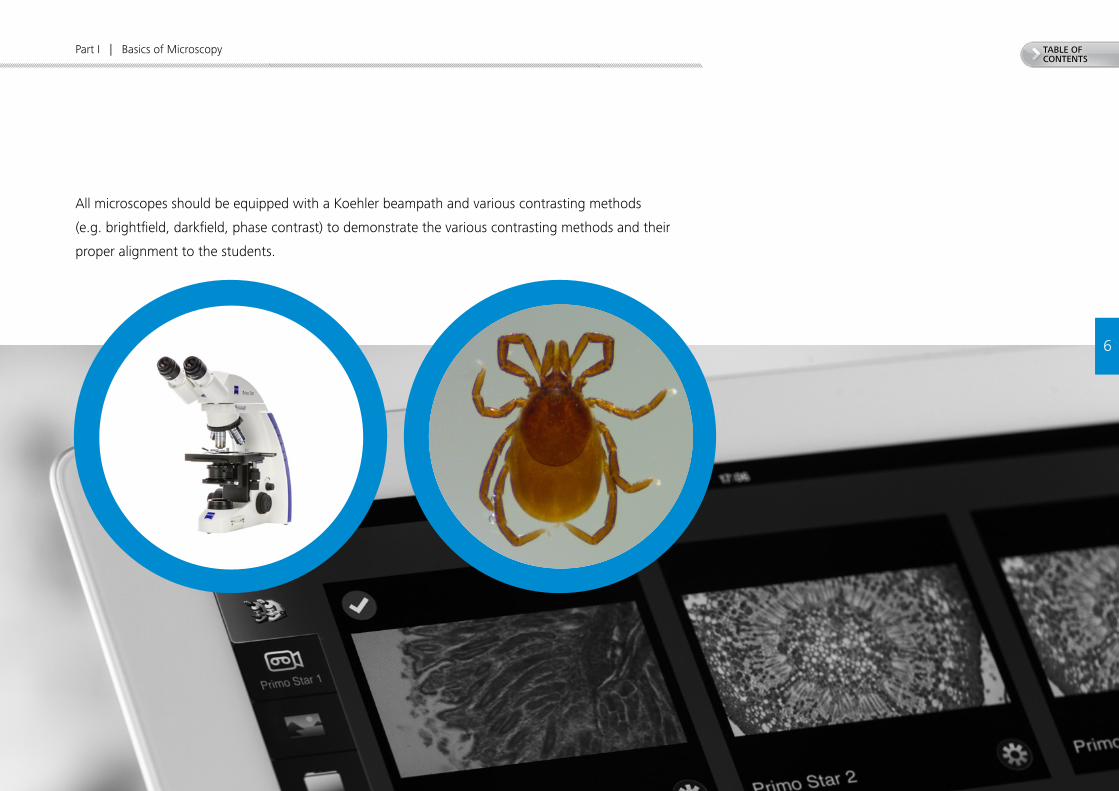
All microscopes should be equipped with a Koehler beampath and various contrasting methods
(e.g. brightfield, darkfield, phase contrast) to demonstrate the various contrasting methods and their
proper alignment to the students.
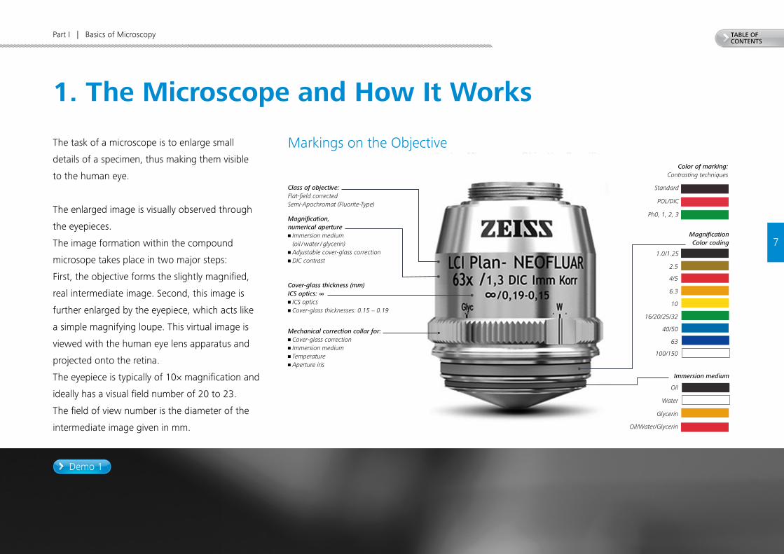
TABLE OF CONTENTS
Demo 1
7
Part I | Basics of Microscopy
1. The Microscope and How It Works
The task of a microscope is to enlarge small
details of a specimen, thus making them visible
to the human eye.
The enlarged image is visually observed through
the eyepieces.
The image formation within the compound
microsope takes place in two major steps:
First, the objective forms the slightly magnified,
real intermediate image. Second, this image is
further enlarged by the eyepiece, which acts like
a simple magnifying loupe. This virtual image is
viewed with the human eye lens apparatus and
projected onto the retina.
The eyepiece is typically of 10× magnification and
ideally has a visual field number of 20 to 23.
The field of view number is the diameter of the
intermediate image given in mm.
Class of objective:Flat-field correctedSemi-Apochromat (Fluorite-Type)
Magnification, numerical aperture• Immersion medium
(oil / water / glycerin)• Adjustable cover-glass correction• DIC contrast
Cover-glass thickness (mm)ICS optics: ∞• ICS optics• Cover-glass thicknesses: 0.15 − 0.19
Mechanical correction collar for:• Cover-glass correction• Immersion medium• Temperature• Aperture iris
Markings on the ObjectiveColor of marking:
Contrasting techniques
Standard
POL/DIC
Ph0, 1, 2, 3
1.0/1.25
2.5
4/5
6.3
10
16/20/25/32
40/50
63
100/150
MagnificationColor coding
Immersion medium
Oil
Water
Glycerin
Oil/Water/Glycerin

+
Demo 2 Demo 3 Demo 4
TABLE OF CONTENTS
8
Part I | Basics of Microscopy
Classes of ObjectivesAchro (Greek: colorless)
Achromatic objectives are corrected for two colors and do
not produce strong bands of color (chromatic aberration)
around the details of the image. Sometimes the prefix
achro is replaced by the prefix “A,” such as in “A-Plan.”
Apochromat (Greek: free of color)
Objectives that have no visually detectable traces of color
fringes. Apochromatic objectives are corrected for three
colors.
D
Objectives are designed for use with or without an immer-
sion liquid for establishing contact between the front lens
and the sample surface (usually the cover glass surface).
Most commonly used is the standard 0.17 mm cover glass;
such objectives therefore frequently bear the marking
D = 0.17. Sometimes a cover glass is not permitted (D = 0).
Epi (Greek: from above)
Indicates objectives suitable for reflected light work
(Greek: “from above”) such as the ZEISS Epiplan. Ob-
jectives for transmitted light lack this designation, for
example the ZEISS Plan.
Korr objective
Objectives with a correction collar can be used with cover
glasses of varying thickness.
LD (long distance)
LD objectives provide an extended working distance usually
with lower N.A. values, corresponding to a slightly lower
resolution.
Oil, W, Glyc, LCI
As demonstrated in 1847 by the Italian physicist Giovanni
Battista Amici (1786 – 1863), when direct contact is estab-
lished between the front lens of the objective and the sample
by means of a liquid such as water, image sharpness and
brightness increase dramatically. These media are referred
to as immersion liquids. Today synthetic immersion oils,
glycerin, water, or silicone oil are used as immersion fluids.
Immersion objectives can bear the marking Oil, W, Glyc, or
LCl depending on their design.
Plan (Greek: flat)
Plan objectives are calculated to eliminate the field curva-
ture providing a flat image, sharp to the edges. As flatness
if image is of particular importance for reflected light appli-
cations, all Epi objectives are flat-field corrected all the way
to the edge. This is not necessarily the case for transmitted
light objectives which are used mainly in biology and med-
icine. In these cases, the simpler A-Plan types have a lower
flat-field correction as compared with the higher class of
objective, the N-ACHROPLAN.
Dry objectives
Objectives designed for use without an immersion fluid
are referred to as dry objectives.
Dry objectives of low magnification are not sensitive for the
use with or without a cover glass. For this reason they are
marked “-” (insensitive).
» The Microscope and How It Works
+
TABLE OF CONTENTS
Part I | Basics of Microscopy
9
Adjusting the eyepieces ensures that both the human
eye and the camera are focused on the same, coincident
focal plane. If you need eyeglasses or contact lenses,
wear them. First, adjust all focusable eyepieces to the
zero mark (if there are crosshairs, this is the red dot;
without crosshairs, the white dot is used). Look into
the fixed or focusable eyepiece already adjusted to the
zero mark. With this eyepiece, focus on a small, distinct
structure (the right eye is always used to look through
the right eyepiece) using the fine focus knob on the
microscope. The image for the other eye is adjusted by
bringing the image of this structure into focus using only
the eye lens focussing ring on the eyepiece.
In the unlikely event that the camera focus is not coin-
cident with the adjusted eyepieces, the height of the
camera adapter must be altered.
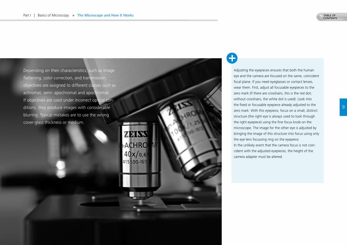
Depending on their characteristics, such as image
flattening, color correction, and transmission,
objectives are assigned to different classes such as
achromat, semi- apochromat and apochromat.
If objectives are used under incorrect optical con-
ditions, they produce images with considerable
blurring. Typical mistakes are to use the wrong
cover-glass thickness or medium.
» The Microscope and How It Works
10
TABLE OF CONTENTS
Primo Star
Eyepieces
Binocular tube head
Stand
Nosepiece turret
Stage
Condenser
Light exit opening with field stop (Koehler illumination), transmitted light beam path and light source
Objective
Specimen holder Specimen
Fine focus drive
Coarse focus drive
Part I | Basics of Microscopy
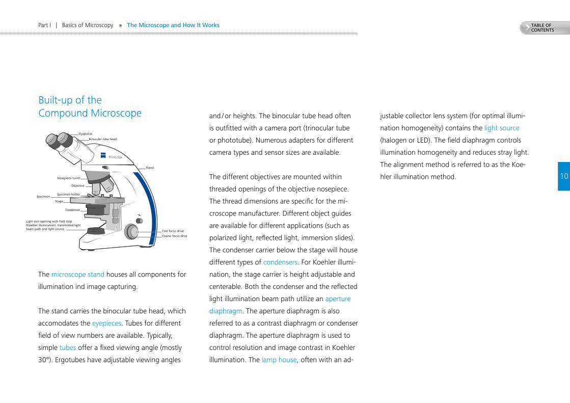
Built-up of the Compound Microscope
The microscope stand houses all components for
illumination ind image capturing.
The stand carries the binocular tube head, which
accomodates the eyepieces. Tubes for different
field of view numbers are available. Typically,
simple tubes offer a fixed viewing angle (mostly
30°). Ergotubes have adjustable viewing angles
and / or heights. The binocular tube head often
is outfitted with a camera port (trinocular tube
or phototube). Numerous adapters for different
camera types and sensor sizes are available.
The different objectives are mounted within
threaded openings of the objective nosepiece.
The thread dimensions are specific for the mi-
croscope manufacturer. Different object guides
are available for different applications (such as
polarized light, reflected light, immersion slides).
The condenser carrier below the stage will house
different types of condensers. For Koehler illumi-
nation, the stage carrier is height adjustable and
centerable. Both the condenser and the reflected
light illumination beam path utilize an aperture
diaphragm. The aperture diaphragm is also
referred to as a contrast diaphragm or condenser
diaphragm. The aperture diaphragm is used to
control resolution and image contrast in Koehler
illumination. The lamp house, often with an ad-
justable collector lens system (for optimal illumi-
nation homogeneity) contains the light source
(halogen or LED). The field diaphragm controls
illumination homogeneity and reduces stray light.
The alignment method is referred to as the Koe-
hler illumination method.
» The Microscope and How It Works
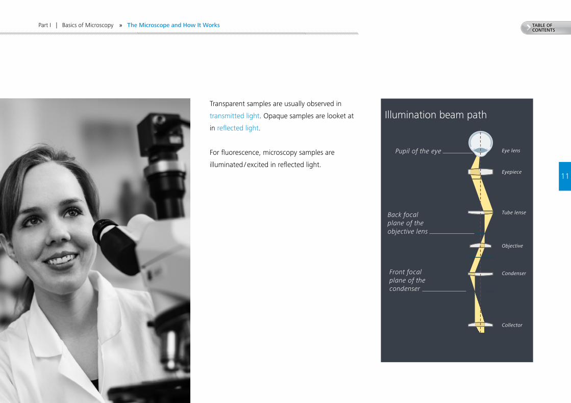
TABLE OF CONTENTS
Part I | Basics of Microscopy
11
Pupil of the eye
Eye lens
Eyepiece
Tube lense
Back focal plane of the objective lens
Objective
CondenserFront focal plane of the condenser
Collector
Lamp filament Lamp
Illumination beam pathTransparent samples are usually observed in
transmitted light. Opaque samples are looket at
in reflected light.
For fluorescence, microscopy samples are
illuminated / excited in reflected light.
» The Microscope and How It Works
12
TABLE OF CONTENTS
Part I | Basics of Microscopy
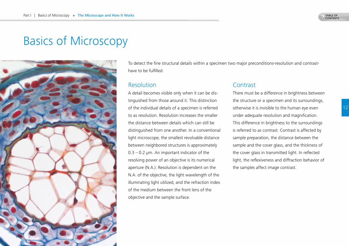
Basics of Microscopy
ResolutionA detail becomes visible only when it can be dis-
tinguished from those around it. This distinction
of the individual details of a specimen is referred
to as resolution. Resolution increases the smaller
the distance between details which can still be
distinguished from one another. In a conventional
light microscope, the smallest revolvable distance
between neighbored structures is approximately
0.3 – 0.2 µm. An important indicator of the
resolving power of an objective is its numerical
aperture (N.A.). Resolution is dependent on the
N.A. of the objective, the light wavelength of the
illuminating light utilized, and the refraction index
of the medium between the front lens of the
objective and the sample surface.
ContrastThere must be a difference in brightness between
the structure or a specimen and its surroundings,
otherwise it is invisible to the human eye even
under adequate resolution and magnification.
This difference in brightness to the surroundings
is referred to as contrast. Contrast is affected by
sample preparation, the distance between the
sample and the cover glass, and the thickness of
the cover glass in transmitted light. In reflected
light, the reflexiveness and diffraction behavior of
the samples affect image contrast.
To detect the fine structural details within a specimen two major preconditions-resolution and contrast-
have to be fulfilled.
» The Microscope and How It Works
13
TABLE OF CONTENTS
Demo 5
Part I | Basics of Microscopy
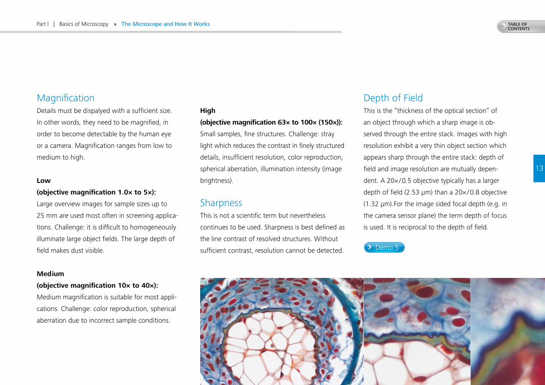
MagnificationDetails must be dispalyed with a sufficient size.
In other words, they need to be magnified, in
order to become detectable by the human eye
or a camera. Magnification ranges from low to
medium to high.
Low
(objective magnification 1.0× to 5×):
Large overview images for sample sizes up to
25 mm are used most often in screening applica-
tions. Challenge: it is difficult to homogeneously
illuminate large object fields. The large depth of
field makes dust visible.
Medium
(objective magnification 10× to 40×):
Medium magnification is suitable for most appli-
cations. Challenge: color reproduction, spherical
aberration due to incorrect sample conditions.
High
(objective magnification 63× to 100× (150×)):
Small samples, fine structures. Challenge: stray
light which reduces the contrast in finely structured
details, insufficient resolution, color reproduction,
spherical aberration, illumination intensity (image
brightness).
SharpnessThis is not a scientific term but nevertheless
continues to be used. Sharpness is best defined as
the line contrast of resolved structures. Without
sufficient contrast, resolution cannot be detected.
Depth of FieldThis is the “thickness of the optical section” of
an object through which a sharp image is ob-
served through the entire stack. Images with high
resolution exhibit a very thin object section which
appears sharp through the entire stack: depth of
field and image resolution are mutually depen-
dent. A 20× / 0.5 objective typically has a larger
depth of field (2.53 µm) than a 20× / 0.8 objective
(1.32 µm).For the image sided focal depth (e.g. in
the camera sensor plane) the term depth of focus
is used. It is reciprocal to the depth of field.
» The Microscope and How It Works
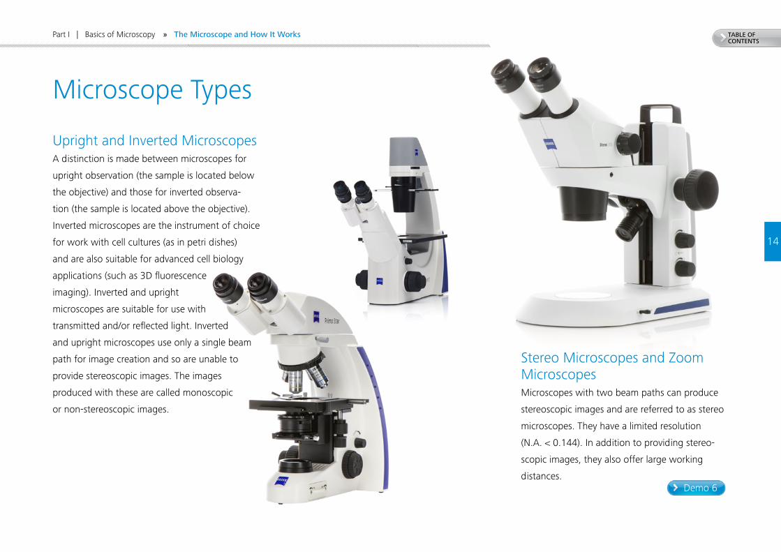
TABLE OF CONTENTS
14
Demo 6
Part I | Basics of Microscopy
Microscope Types
Upright and Inverted MicroscopesA distinction is made between microscopes for
upright observation (the sample is located below
the objective) and those for inverted observa-
tion (the sample is located above the objective).
Inverted microscopes are the instrument of choice
for work with cell cultures (as in petri dishes)
and are also suitable for advanced cell biology
applications (such as 3D fluorescence
imaging). Inverted and upright
microscopes are suitable for use with
transmitted and/or reflected light. Inverted
and upright microscopes use only a single beam
path for image creation and so are unable to
provide stereoscopic images. The images
produced with these are called monoscopic
or non-stereoscopic images.
Stereo Microscopes and Zoom MicroscopesMicroscopes with two beam paths can produce
stereoscopic images and are referred to as stereo
microscopes. They have a limited resolution
(N.A. < 0.144). In addition to providing stereo-
scopic images, they also offer large working
distances.
» The Microscope and How It Works
15
TABLE OF CONTENTS
Demo 7
Part I | Basics of Microscopy
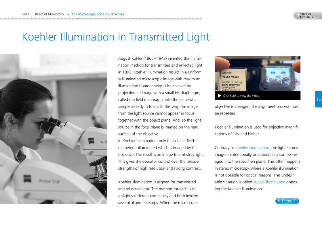
Koehler Illumination in Transmitted Light
August Köhler (1866 – 1948) invented this illumi-
nation method for transmitted and reflected light
in 1892. Koehler illumination results in a uniform-
ly illuminated microscopic image with maximum
illumination homogeneity. It is achieved by
projecting an image with a small iris diaphragm,
called the field diaphragm, into the plane of a
sample already in focus. In this way, the image
from the light source cannot appear in focus
together with the object plane. And, so the light
source in the focal plane is imaged on the rear
surface of the objective.
In Koehler illumination, only that object field
diameter is illuminated which is imaged by the
objective. The result is an image free of stray light.
This gives the operator control over the relative
strengths of high resolution and strong contrast.
Koehler illumination is aligned for transmitted
and reflected light. The method for each is of
a slightly different complexity and both involve
several alignment steps. When the microscope
objective is changed, the alignment process must
be repeated.
Koehler illumination is used for objective magnifi-
cations of 10× and higher.
Contrary to Koehler illumination, the light source
image unintentionally or accidentially can be im-
aged into the specimen plane. This often happens
in stereo microscopy, where a Koehler illumination
is not possible for optical reasons. This undesir-
able situation is called critical illumination oppos-
ing the Koehler illumination.
» The Microscope and How It Works
Click here to view the video.
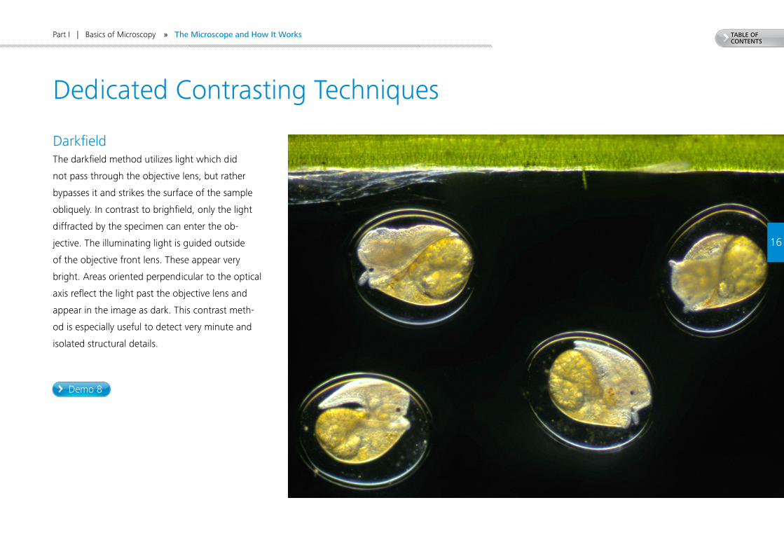
TABLE OF CONTENTS
Demo 8
16
Part I | Basics of Microscopy
Dedicated Contrasting Techniques
Darkfield The darkfield method utilizes light which did
not pass through the objective lens, but rather
bypasses it and strikes the surface of the sample
obliquely. In contrast to brighfield, only the light
diffracted by the specimen can enter the ob-
jective. The illuminating light is guided outside
of the objective front lens. These appear very
bright. Areas oriented perpendicular to the optical
axis reflect the light past the objective lens and
appear in the image as dark. This contrast meth-
od is especially useful to detect very minute and
isolated structural details.
» The Microscope and How It Works
+
Demo 10
Demo 9
TABLE OF CONTENTS
17
Part I | Basics of Microscopy » The Microscope and How It Works
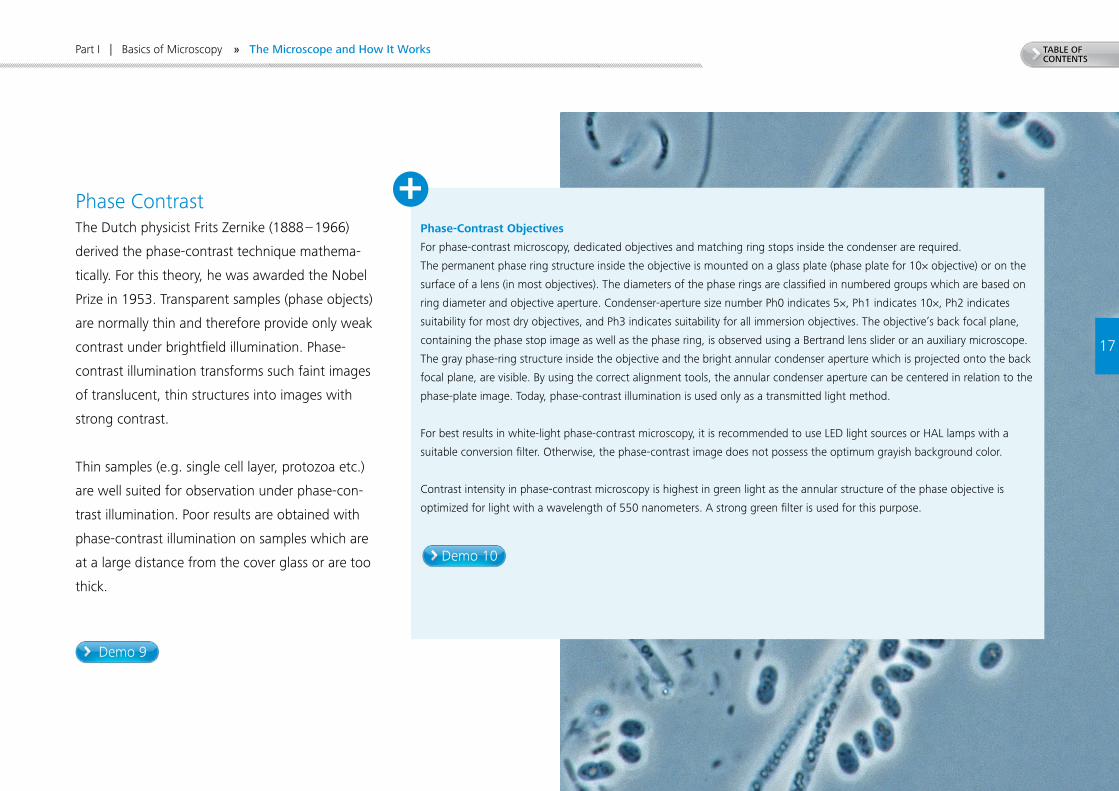
Phase Contrast The Dutch physicist Frits Zernike (1888 – 1966)
derived the phase-contrast technique mathema-
tically. For this theory, he was awarded the Nobel
Prize in 1953. Transparent samples (phase objects)
are normally thin and therefore provide only weak
contrast under brightfield illumination. Phase-
contrast illumination transforms such faint images
of translucent, thin structures into images with
strong contrast.
Thin samples (e.g. single cell layer, protozoa etc.)
are well suited for observation under phase-con-
trast illumination. Poor results are obtained with
phase-contrast illumination on samples which are
at a large distance from the cover glass or are too
thick.
Phase-Contrast Objectives
For phase-contrast microscopy, dedicated objectives and matching ring stops inside the condenser are required.
The permanent phase ring structure inside the objective is mounted on a glass plate (phase plate for 10× objective) or on the
surface of a lens (in most objectives). The diameters of the phase rings are classified in numbered groups which are based on
ring diameter and objective aperture. Condenser-aperture size number Ph0 indicates 5×, Ph1 indicates 10×, Ph2 indicates
suitability for most dry objectives, and Ph3 indicates suitability for all immersion objectives. The objective’s back focal plane,
containing the phase stop image as well as the phase ring, is observed using a Bertrand lens slider or an auxiliary microscope.
The gray phase-ring structure inside the objective and the bright annular condenser aperture which is projected onto the back
focal plane, are visible. By using the correct alignment tools, the annular condenser aperture can be centered in relation to the
phase-plate image. Today, phase-contrast illumination is used only as a transmitted light method.
For best results in white-light phase-contrast microscopy, it is recommended to use LED light sources or HAL lamps with a
suitable conversion filter. Otherwise, the phase-contrast image does not possess the optimum grayish background color.
Contrast intensity in phase-contrast microscopy is highest in green light as the annular structure of the phase objective is
optimized for light with a wavelength of 550 nanometers. A strong green filter is used for this purpose.
18
TABLE OF CONTENTS
Part I | Basics of Microscopy
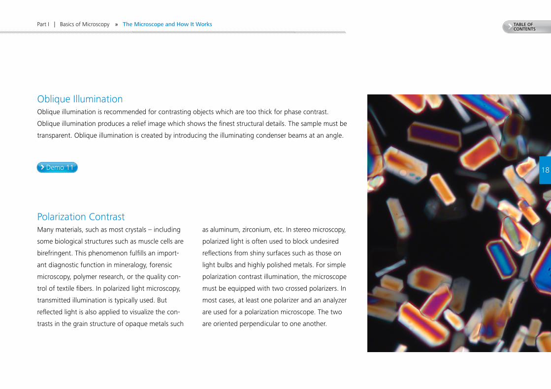
Oblique IlluminationOblique illumination is recommended for contrasting objects which are too thick for phase contrast.
Oblique illumination produces a relief image which shows the finest structural details. The sample must be
transparent. Oblique illumination is created by introducing the illuminating condenser beams at an angle.
Polarization ContrastMany materials, such as most crystals – including
some biological structures such as muscle cells are
birefringent. This phenomenon fulfills an import-
ant diagnostic function in mineralogy, forensic
microscopy, polymer research, or the quality con-
trol of textile fibers. In polarized light microscopy,
transmitted illumination is typically used. But
reflected light is also applied to visualize the con-
trasts in the grain structure of opaque metals such
as aluminum, zirconium, etc. In stereo microscopy,
polarized light is often used to block undesired
reflections from shiny surfaces such as those on
light bulbs and highly polished metals. For simple
polarization contrast illumination, the microscope
must be equipped with two crossed polarizers. In
most cases, at least one polarizer and an analyzer
are used for a polarization microscope. The two
are oriented perpendicular to one another.
Demo 11
» The Microscope and How It Works
Demo 12
TABLE OF CONTENTS
19
Part I | Basics of Microscopy » The Microscope and How It Works
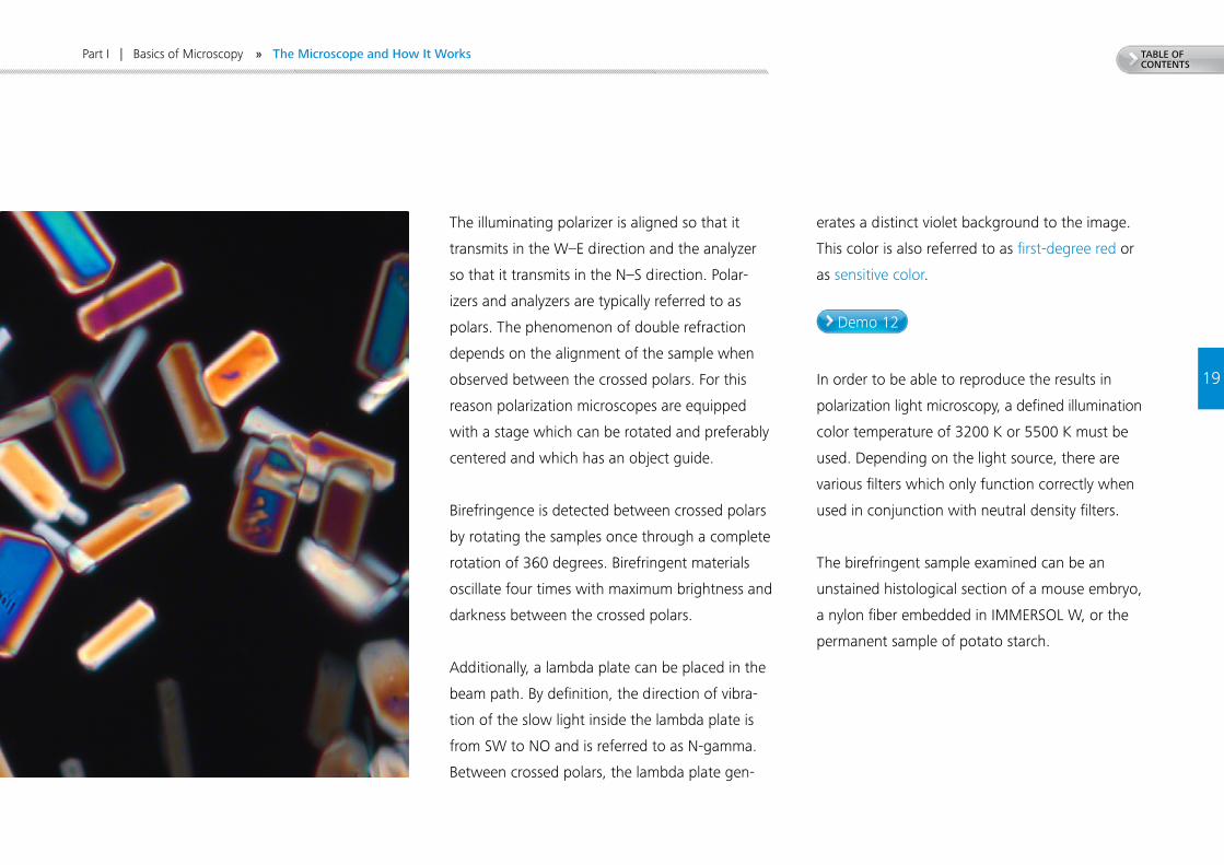
The illuminating polarizer is aligned so that it
transmits in the W–E direction and the analyzer
so that it transmits in the N–S direction. Polar-
izers and analyzers are typically referred to as
polars. The phenomenon of double refraction
depends on the alignment of the sample when
observed between the crossed polars. For this
reason polarization microscopes are equipped
with a stage which can be rotated and preferably
centered and which has an object guide.
Birefringence is detected between crossed polars
by rotating the samples once through a complete
rotation of 360 degrees. Birefringent materials
oscillate four times with maximum brightness and
darkness between the crossed polars.
Additionally, a lambda plate can be placed in the
beam path. By definition, the direction of vibra-
tion of the slow light inside the lambda plate is
from SW to NO and is referred to as N-gamma.
Between crossed polars, the lambda plate gen-
erates a distinct violet background to the image.
This color is also referred to as first-degree red or
as sensitive color.
In order to be able to reproduce the results in
polarization light microscopy, a defined illumination
color temperature of 3200 K or 5500 K must be
used. Depending on the light source, there are
various filters which only function correctly when
used in conjunction with neutral density filters.
The birefringent sample examined can be an
unstained histological section of a mouse embryo,
a nylon fiber embedded in IMMERSOL W, or the
permanent sample of potato starch.
TABLE OF CONTENTS
Demo 1 Demo 3 Demo 5
Demo 2
20
Part I | Basics of Microscopy » Practical Demonstrations of How a Microscope Works
2. Practical Demonstrations of How a Microscope Works
Image Formation in a Microscope
The trainer demonstrates the intermediate image using a
histological section of a mouse embryo stained with AZAN
(LIEDER), under 10× magnification in brightfield by removing
the eyepiece and inserting a long, thin piece of paper held at
a slant or a small piece of frosted glass on a stem.
Color Correction of Various Classes of Objective
The trainer demonstrates the various color-correction stages
using a histological section stained with iron haematoxylin
(LIEDER). Both samples have no color of their own and all
visible color bands demonstrate the chromatic response of
the objectives. A good comparison can be drawn between
the simpler achromat objective (such as A-Plan 40× / 0.65)
and a semi-apochromat objective (such as EC Plan-NEOFLUAR
40× / 0.75).
Cover-Glass Thickness
The trainer demonstrates the effects of using the wrong
cover-glass thickness by directly comparing it with the
correct one. A too-thick cover glass can be created for this
purpose by stacking two cover glasses on top of one anoth-
er with a drop of IMMERSOL in between. N-ACHROPLAN
50 / 1.0 Oil is recommended as the immersion objective for
these demonstrations.
Objective with Correction Collar
The trainer demonstrates correct use of an objective with a
correction collar. The function of the correction collar is best
demonstrated using an LD EC Plan-NEOFLUAR 40 / 0.6 Korr
Ph2 objective in phase contrast with an unstained histologi-
cal section such as that of a rabbit tongue.
The Effects of the Aperture
The trainer presents a prepared slide of a diatom shell (Klaus
Kemp, UK, diatoms.co.uk) under brightfield transmitted light
using a small and a large illumination aperture to demon-
strate the differences in detail rendering and depths of field.
Demo 4
21
TABLE OF CONTENTS
Demo 7Demo 6
Part I | Basics of Microscopy
Alignment for Koehler Illumination
It is recommended to use a stained histological section such
as slides of the “mouse embryo” or the “snail” “Helix poma-
tia” (LIEDER). The microscope should not be set up near a
bright window, as this can result in loss of contrast and other
imaging problems such as eye floaters. The optics of the
microscope also suffer under changes in temperature near
unprotected windows.
Before the demonstration of the Koehler illumination begins,
adjustment of the eyepiece / tube and the light source is
demonstrated. The pupil distance of the tube is set to a value
at which only a single, unified circle displays the image field
of the microscope simultaneously for both eyes. First, the
eyepieces are set to the zero mark (“white dot” = without
crosshairs, “red dot” = with crosshairs). When using crosshairs
such as provided by an ocular micrometer (Pol crosshairs), the
image can be focused with the eye lens of the eyepiece most
easily in front of a light background outside the microscope.
After both eyepieces are inserted, the focus knob of the micro-
scope is used to focus on a fine structure for one eyepiece at
medium object magnification. The other eyepiece is focused in
correspondence with the focus on such a focused object using
the focus for the eye lens of the eyepiece.
Parfocality
The trainer demonstrates the parfocality adjustment for the
entire zoom range and harmonization between the visual
image and the camera image. The eyepieces must be adjust-
ed in the same manner as for any conventional microscope.
Since Stemi 305 is not equipped with a dioptric eyepiece
scale, each eyepiece is adjusted to the height at which the
field diaphragm of the eyepiece appears at maximum sharp-
ness without chromatic aberration. To adjust the parfocality,
Stemi 305 / Stemi 508 are focused on a sample detail with
the greatest possible contrast. Then the zoom magnification
is set to maximum. The image is focused again. When zoom
magnification is reduced, the image should remain in focus.
At maximum zoom magnification, the depth of field is lowest
and the numerical aperture greatest. Since the accommo-
dation depth is also low, it is easy to exactly focus on a fine
detail with the eye. At a minimal zoom magnification, the
depth of field is small and the camera image can be precisely
focused using parfocal stereo microscopy.
First, the image of the HAL 100 lamp is projected onto a
homogeneous wall. The trainer explains that for optimum
homogeneity of illumination the two images from the lamp
(direct image or mirror image) must have a particular orien-
tation to one another. When the HAL 100 image is projected
onto a wall, both images should be focused such that they
both produce the clearest image possible. These images
should be nearly identical in size. They should overlap by
approx. 50%. The next step in adjusting the lamp is to insert
the lamp housing into the microscope. Remove any diffusing
lenses from the light path. Focus on the sample image and
open the condenser aperture. Observe the light source in the
rear focal plane of the objective using the Bertrand lens slider
(optional: remove one eyepiece; auxiliary microscope).
Use the SW 3 set screws of the lamp housing to shift the
images of the filaments until the rear focal plane is homo-
geneously filled with light and filament structures from both
lamp images completely and uniformly cover the rear focal
plane.
This is easiest to see at objective magnifications of 40× or
higher. After the lamp has been adjusted, the diffuser lens is
reinserted in the light path.
» Practical Demonstrations of How a Microscope Works
22
TABLE OF CONTENTS
Part I | Basics of Microscopy
Next, the alignment steps for Koehler illumination are per-
formed as described.
In this exercise, the position of the following planes must be
demonstrated: light-source image planes (front focal plane
of the condenser, observed by inclining an empty slide under
the closed aperture diaphragm, rear focal plane of the objec-
tive with aperture diaphragm open, use of the Bertrand lens
system, exit pupil of the eyepiece with diffuser glass), object,
and object image planes (focused sample plane, intermediate
image plane with diffuser glass plate inside the tube, final
camera or retina image with additional magnifiers/eyepieces
and diffuser glass).
It is recommended to demonstrate the effect of the field dia-
phragm on stray light reduction by asking the participants to
observe the inside walls of the tube (without looking directly
into the beam of light) with the field diaphragm fully open,
in contrast to those field-diaphragm diameters as used in
the Koehler method. When the field diaphragm is fully open,
rings of stray light are visible. These are blocked when the
field diaphragm is correctly adjusted.
First, all participants practice the Koehler alignment method
using already adjusted microscopes and a stained histolo-
gical section. In a second step, the microscope settings are
changed by a participant and must be corrected by another
participant without changing the objective. Then, each
participant can demonstrate the correct adjustment step
and the objective is changed. The participants are given the
task of describing the effects of changing the objective on
the diameters of the field and aperture diaphragms. It is
helpful here to prepare a schematic drawing together with
all participants. The aperture cones from the light source can
best be examined using a cube of frosted glass.
The participants now change the aperture diaphragm
diameter in small steps and observe the effect of changing
diameter on image contrast and the rendering of details
in fine structures in a transparent, unstained histological
section.
» Practical Demonstrations of How a Microscope Works
Demo 8 Demo 9
TABLE OF CONTENTS
23
Demo 10
Part I | Basics of Microscopy
Darkfield Transmitted Light
Darkfield ring light is centered by observing the rear focal
plane of the objective. Using the centering tools, the dark-
field ring is aligned concentrically with the edge of the pupil
of the rear focal plane.
If possible, the darkfield mirror image should be demon-
strated. Adjustment of the darkfield mirror image can be
demonstrated most easily using the paraboloid dry condens-
er 0.8 / 0.95 together with the condenser mount Z. There
are two options for adjusting darkfield: The first method
consists of centering the image of the field diaphragm at the
same height of the condenser at which the field diaphragm
is imaged in the sample plane. This works best with an
immersion objective. After centering the field-diaphragm
image, open the field diaphragm completely and alter the
condenser height to darkfield. It is often the case that the
field-diaphragm image is not easy to detect. For this reason,
many microscopists favor the second method: Use a 20× dry
objective. Alter the height of the darkfield condenser until
a dark brownish spot appears in the center. This is the cross
above the point of the rays of the darkfield mirror image.
If necessary, the dark spot can be centered using the x/y
adjustment screws of the condenser. Now, move the con-
denser to the height at which the darkfield image appears
to be most homogeneous. When using an iris-diaphragm
immersion objective for darkfield, the iris diaphragm is closed
until an optimal darkfield is achieved. This requires a strong
light source (microLED, HAL 100). Use a conversion filter.
Darkfield microscopy of plankton samples, hay infusions of
soil, and pond water (one or two weeks old); in particular
the organic surface film of such cultures, when removed with
a cover glass and observed in darkfield, does a nice job of
showing bacteria and small protists.
To achieve good results with store-bought slides and cover
glasses in darkfield microscopy, these must be cleaned with
ethanol or dishwashing liquid, rinsed with a large amount of
demineralized water, and wiped dry.
Phase-Contrast Microscopy
This can be demonstrated using live yeast cells which do not
yield their internal structure to viewing unless they have been
perfectly compacted and affixed to the underside of the cov-
er glass. When they are pressed flat, their nuclei and other
organelles become visible. The cells of the onion are perfectly
suited for a demonstration of the organelle inventory of the
fuel cell. The onion must be fresh because old onions are
unsuitable for use under phase-contrast illumination due to
an incorrect refraction behavior (similarity / congruence of the
index of refraction between the structure and the surround-
ing medium).
Phase-Contrast Microscopy:
Adjusting the Phase Ring
Adjustment of the phase ring is demonstrated and practiced
by the participants using the unstained histological section of
a rabbit tongue.
The trainer explains and demonstrates the alignment of the
phase annular diaphragm. Each participant carefully repeats
the steps of the alignment procedure.
» Practical Demonstrations of How a Microscope Works
24
TABLE OF CONTENTS
Demo 11 Demo 12
Part I | Basics of Microscopy
The trainer also demonstrates the phenomenon that
phase-contrast images have a large depth of field. This is one
of the reasons why phase contrast is unsuitable for thicker
samples.
In a further step, it is demonstrated that phase-contrast
objectives with a magnification of 40× and more destroy
image contrast when used for critical brightfield tasks such
as those in hematology. This is best demonstrated using a
40× phase-contrast objective (e.g. A-Plan 40× Ph2).
The trainer also demonstrates the advantage of a strong
green filter for increasing the contrast of fine structural
details in phase contrast. Preparation of the upper epidermis
of the skin (inside surface) of an onion is recommended.
Thin leaves of the waterweed Egeria densa or the ruffled
Aponogeton Aponogeton crispus can also be used.
The sample should be mounted so that upper surfaces of
the leaves are facing the objective.
Oblique Illumination
Oblique illumination is demonstrated using a 20× objective
magnification and a transparent biological sample (such as
the unstained histological thin section of an embryo / plank-
ton sample). Remove the eyepiece to show the focal plane
of the objective. By turning the condenser turret, adjust
the aperture diaphragm of the universal Ph condenser
(brightfield position) to a position in which the image of the
completely closed aperture iris diaphragm is displaced to the
outer edge of the rear focal plane. A phase-contrast annular
diaphragm which is too large for a given objective aperture
(in this case Ph 3) also produces a somewhat more uniform
but softer oblique illumination.
Polarization Contrast
When a birefringent detail is rotated between crossed polars
using a lambda plate, it can be seen that most structures
appear four times each in blue and yellow. If the long
morphological axis of a cylindrical crystal appears blue in
what is referred to as its positive quadrant position (SW–NO),
this structure has a positive optical character. If its blue
polarization color appears in the NW–SO quadrant, it has a
negative optical character. With this knowledge, it is possible
to distinguish between optical objects in a brightfield envi-
ronment which otherwise would not be distinguishable.
The trainer demonstrates the adjustment of the crossed
polars and the use of the lambda plate.
» Practical Demonstrations of How a Microscope Works
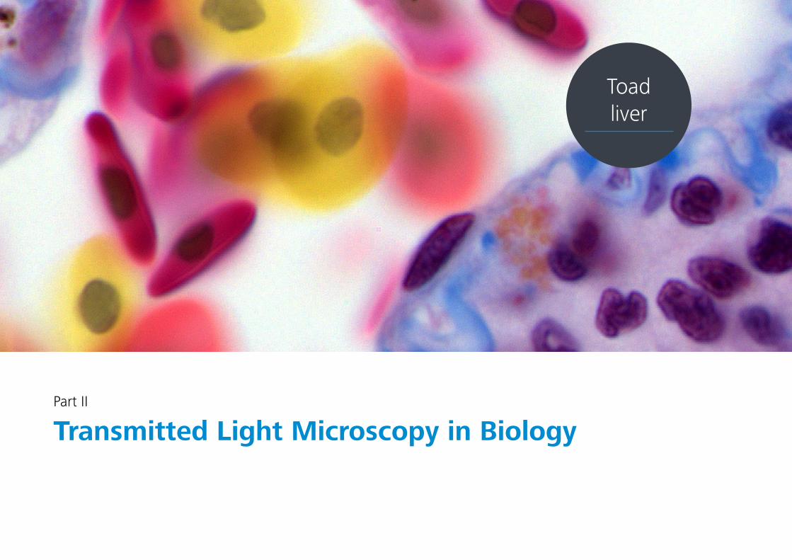
Part II
Transmitted Light Microscopy in Biology
Toad liver
26
TABLE OF CONTENTS
Part II | Transmitted Light Microscopy in Biology
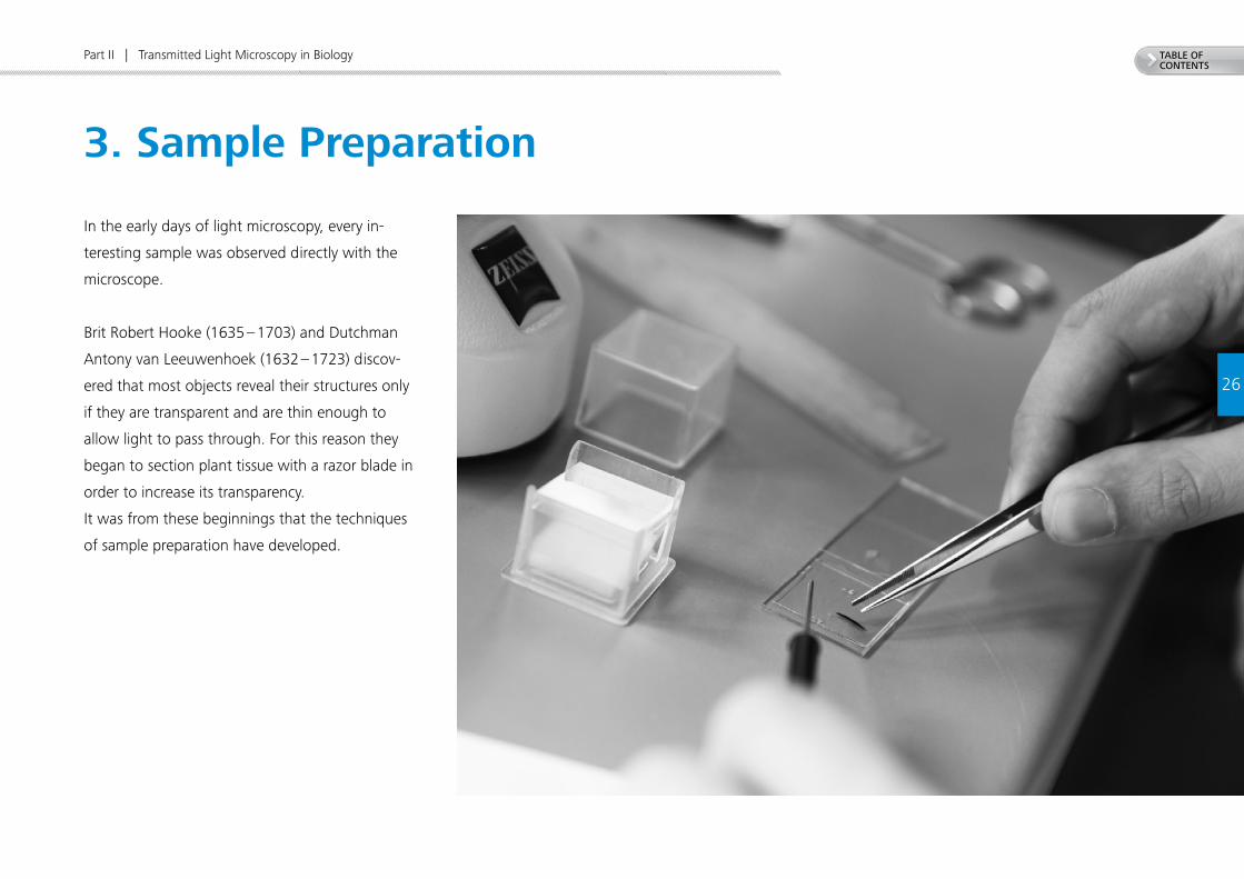
3. Sample Preparation
In the early days of light microscopy, every in-
teresting sample was observed directly with the
microscope.
Brit Robert Hooke (1635 – 1703) and Dutchman
Antony van Leeuwenhoek (1632 – 1723) discov-
ered that most objects reveal their structures only
if they are transparent and are thin enough to
allow light to pass through. For this reason they
began to section plant tissue with a razor blade in
order to increase its transparency.
It was from these beginnings that the techniques
of sample preparation have developed.
27
TABLE OF CONTENTS
Part II | Transmitted Light Microscopy in Biology
1 Friedrich-Schiller-Universität Jena, Arbeitsgruppe Biologiedidaktik, 2011, p. 10
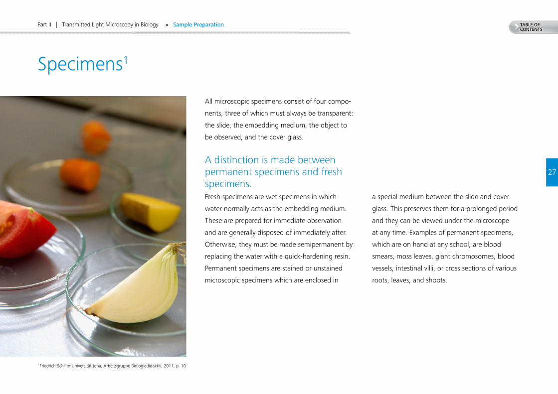
All microscopic specimens consist of four compo-
nents, three of which must always be transparent:
the slide, the embedding medium, the object to
be observed, and the cover glass.
A distinction is made between permanent specimens and fresh specimens. Fresh specimens are wet specimens in which
water normally acts as the embedding medium.
These are prepared for immediate observation
and are generally disposed of immediately after.
Otherwise, they must be made semipermanent by
replacing the water with a quick-hardening resin.
Permanent specimens are stained or unstained
microscopic specimens which are enclosed in
a special medium between the slide and cover
glass. This preserves them for a prolonged period
and they can be viewed under the microscope
at any time. Examples of permanent specimens,
which are on hand at any school, are blood
smears, moss leaves, giant chromosomes, blood
vessels, intestinal villi, or cross sections of various
roots, leaves, and shoots.
Specimens1
» Sample Preparation
28
TABLE OF CONTENTS
Part II | Transmitted Light Microscopy in Biology
8 Friedrich-Schiller-Universität Jena, Arbeitsgruppe Biologiedidaktik, 2011, p. 11
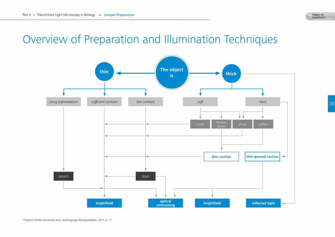
Overview of Preparation and Illumination Techniques
thin thick
crush harden, freeze shred soften
The object is
thin section thin-ground section
bleach stain
brightfield opticalcontrasting brightfield reflected light
stong pigmentation sufficient contrast low contrast soft hard
» Sample Preparation
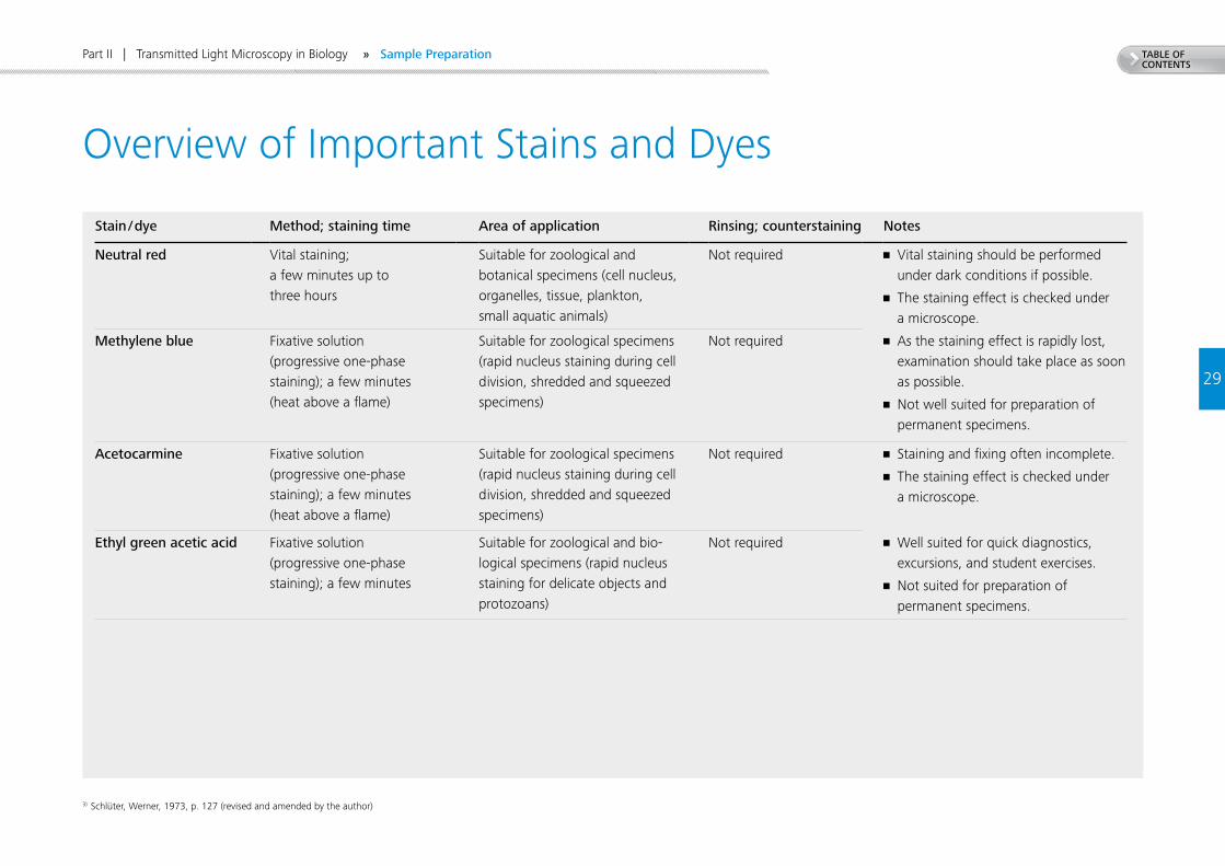
TABLE OF CONTENTS
29
Part II | Transmitted Light Microscopy in Biology
Stain / dye Method; staining time Area of application Rinsing; counterstaining Notes
Neutral red Vital staining; a few minutes up to three hours
Suitable for zoological and botanical specimens (cell nucleus, organelles, tissue, plankton, small aquatic animals)
Not required • Vital staining should be performed under dark conditions if possible.
• The staining effect is checked under a microscope.
Methylene blue Fixative solution (progressive one-phase staining); a few minutes (heat above a flame)
Suitable for zoological specimens (rapid nucleus staining during cell division, shredded and squeezed specimens)
Not required • As the staining effect is rapidly lost, examination should take place as soon as possible.
• Not well suited for preparation of permanent specimens.
Acetocarmine Fixative solution (progressive one-phase staining); a few minutes (heat above a flame)
Suitable for zoological specimens (rapid nucleus staining during cell division, shredded and squeezed specimens)
Not required • Staining and fixing often incomplete.
• The staining effect is checked under a microscope.
Ethyl green acetic acid Fixative solution (progressive one-phase staining); a few minutes
Suitable for zoological and bio-logical specimens (rapid nucleus staining for delicate objects and protozoans)
Not required • Well suited for quick diagnostics, excursions, and student exercises.
• Not suited for preparation of permanent specimens.
3) Schlüter, Werner, 1973, p. 127 (revised and amended by the author)
Overview of Important Stains and Dyes
» Sample Preparation
30
TABLE OF CONTENTS
Part II | Transmitted Light Microscopy in Biology
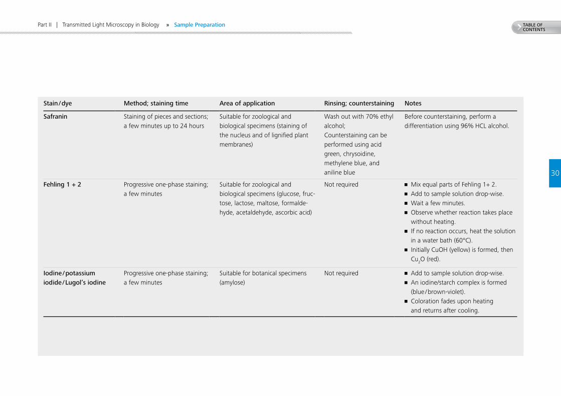
Stain / dye Method; staining time Area of application Rinsing; counterstaining Notes
Safranin Staining of pieces and sections;a few minutes up to 24 hours
Suitable for zoological and biological specimens (staining of the nucleus and of lignified plant membranes)
Wash out with 70% ethyl alcohol; Counterstaining can be performed using acid green, chrysoidine, methylene blue, and aniline blue
Before counterstaining, perform a differentiation using 96% HCL alcohol.
Fehling 1 + 2 Progressive one-phase staining; a few minutes
Suitable for zoological and biological specimens (glucose, fruc-tose, lactose, maltose, formalde-hyde, acetaldehyde, ascorbic acid)
Not required • Mix equal parts of Fehling 1+ 2. • Add to sample solution drop-wise.• Wait a few minutes.• Observe whether reaction takes place
without heating.• If no reaction occurs, heat the solution
in a water bath (60°C).• Initially CuOH (yellow) is formed, then
Cu2O (red).
Iodine / potassium iodide / Lugol’s iodine
Progressive one-phase staining;a few minutes
Suitable for botanical specimens (amylose)
Not required • Add to sample solution drop-wise.• An iodine/starch complex is formed
(blue / brown-violet).• Coloration fades upon heating
and returns after cooling.
» Sample Preparation
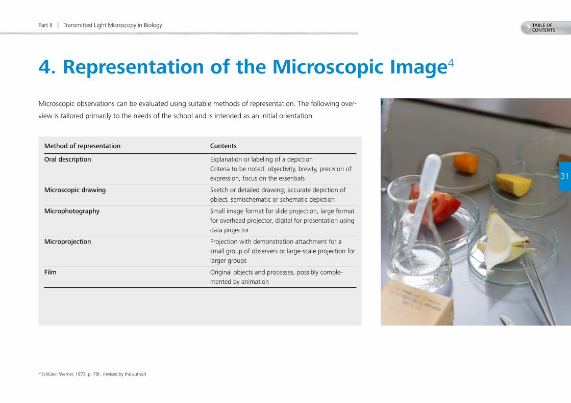
TABLE OF CONTENTS
31
Part II | Transmitted Light Microscopy in Biology
Method of representation Contents
Oral description Explanation or labeling of a depictionCriteria to be noted: objectivity, brevity, precision of expression, focus on the essentials
Microscopic drawing Sketch or detailed drawing; accurate depiction of object, semischematic or schematic depiction
Microphotography Small image format for slide projection, large format for overhead projector, digital for presentation using data projector
Microprojection Projection with demonstration attachment for a small group of observers or large-scale projection for larger groups
Film Original objects and processes, possibly comple-mented by animation
4 Schlüter, Werner, 1973, p. 70f., (revised by the author)
Microscopic observations can be evaluated using suitable methods of representation. The following over-
view is tailored primarily to the needs of the school and is intended as an initial orientation.
4. Representation of the Microscopic Image4
TABLE OF CONTENTS
32
Part II | Transmitted Light Microscopy in Biology
When selecting one of the above methods of representation,
keep in mind the following:
• The ability and knowledge, the experience and inner bearing of the presenter determine the
quality of presentation far more strongly than the scope of effort applied and the modernity
of technological equipment used.
• The method of presentation is selected depending on the aim to be achieved.
There is no generally preferable method, as each has its inherent advantages and
disadvantages.
• The quality of every presentation is strongly defined by the quality of the microscopic
specimens on which it is based.
• The current level of knowledge and ability achieved by the students should be taken into
account when selecting a method.
• Selection of a method may be limited due to unavailable or insufficient materials and technical
prerequisites.
• A suitable combination of several methods can increase the gain in knowledge. The combi-
nation of microphotography and microscopic drawings of the same object provides a great
amount of information.
» Representation of the Microscopic Image
33
TABLE OF CONTENTS
Part II | Transmitted Light Microscopy in Biology
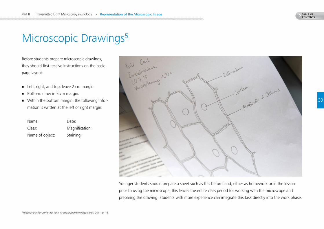
Before students prepare microscopic drawings,
they should first receive instructions on the basic
page layout:
• Left, right, and top: leave 2 cm margin.
• Bottom: draw in 5 cm margin.
• Within the bottom margin, the following infor-
mation is written at the left or right margin:
Name: Date:
Class: Magnification:
Name of object: Staining:
Younger students should prepare a sheet such as this beforehand, either as homework or in the lesson
prior to using the microscope; this leaves the entire class period for working with the microscope and
preparing the drawing. Students with more experience can integrate this task directly into the work phase.
5 Friedrich-Schiller-Universität Jena, Arbeitsgruppe Biologiedidaktik, 2011, p. 18
Microscopic Drawings5
» Representation of the Microscopic Image
34
TABLE OF CONTENTS
Part II | Transmitted Light Microscopy in Biology
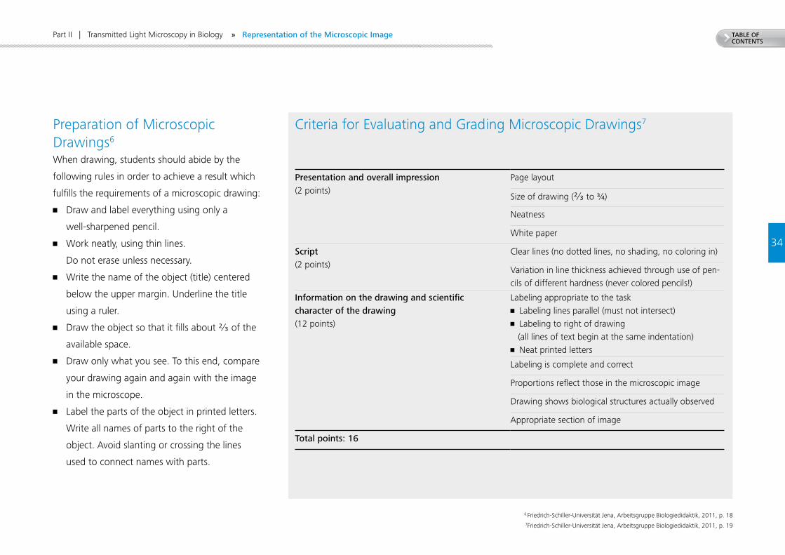
When drawing, students should abide by the
following rules in order to achieve a result which
fulfills the requirements of a microscopic drawing:
• Draw and label everything using only a
well-sharpened pencil.
• Work neatly, using thin lines.
Do not erase unless necessary.
• Write the name of the object (title) centered
below the upper margin. Underline the title
using a ruler.
• Draw the object so that it fills about ²∕₃ of the
available space.
• Draw only what you see. To this end, compare
your drawing again and again with the image
in the microscope.
• Label the parts of the object in printed letters.
Write all names of parts to the right of the
object. Avoid slanting or crossing the lines
used to connect names with parts.
6 Friedrich-Schiller-Universität Jena, Arbeitsgruppe Biologiedidaktik, 2011, p. 187Friedrich-Schiller-Universität Jena, Arbeitsgruppe Biologiedidaktik, 2011, p. 19
Criteria for Evaluating and Grading Microscopic Drawings7
Presentation and overall impression (2 points)
Page layout
Size of drawing (²∕₃ to ¾)
Neatness
White paper
Script(2 points)
Clear lines (no dotted lines, no shading, no coloring in)
Variation in line thickness achieved through use of pen-cils of different hardness (never colored pencils!)
Information on the drawing and scientific character of the drawing(12 points)
Labeling appropriate to the task• Labeling lines parallel (must not intersect)• Labeling to right of drawing (all lines of text begin at the same indentation)• Neat printed letters
Labeling is complete and correct
Proportions reflect those in the microscopic image
Drawing shows biological structures actually observed
Appropriate section of image
Total points: 16
Preparation of Microscopic Drawings6
» Representation of the Microscopic Image
35
TABLE OF CONTENTS
Part II | Transmitted Light Microscopy in Biology
8 Schlüter, Werner, 1973, p. 72
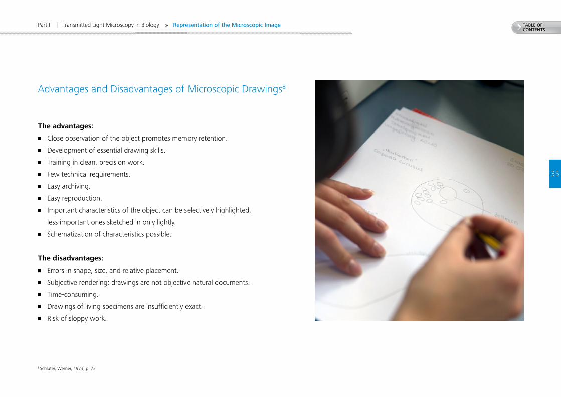
The advantages:
• Close observation of the object promotes memory retention.
• Development of essential drawing skills.
• Training in clean, precision work.
• Few technical requirements.
• Easy archiving.
• Easy reproduction.
• Important characteristics of the object can be selectively highlighted,
less important ones sketched in only lightly.
• Schematization of characteristics possible.
The disadvantages:
• Errors in shape, size, and relative placement.
• Subjective rendering; drawings are not objective natural documents.
• Time-consuming.
• Drawings of living specimens are insufficiently exact.
• Risk of sloppy work.
Advantages and Disadvantages of Microscopic Drawings8
» Representation of the Microscopic Image
9 Gemballa S., Hoßfeld U., Bogner W., 2012, pp. 20–26
36
TABLE OF CONTENTS
Experiment 1
Part II | Transmitted Light Microscopy in Biology
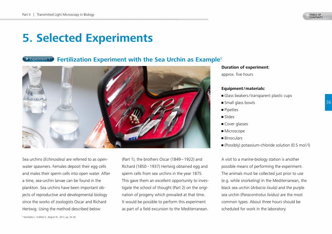
5. Selected Experiments
Sea urchins (Echinoidea) are referred to as open-
water spawners. Females deposit their egg cells
and males their sperm cells into open water. After
a time, sea-urchin larvae can be found in the
plankton. Sea urchins have been important ob-
jects of reproductive and developmental biology
since the works of zoologists Oscar and Richard
Hertwig. Using the method described below
(Part 1), the brothers Oscar (1849 – 1922) and
Richard (1850 – 1937) Hertwig obtained egg and
sperm cells from sea urchins in the year 1875.
This gave them an excellent opportunity to inves-
tigate the school of thought (Part 2) on the origi-
nation of progeny which prevailed at that time.
It would be possible to perform this experiment
as part of a field excursion to the Mediterranean.
Fertilization Experiment with the Sea Urchin as Example9
Duration of experiment:
approx. five hours
Equipment / materials:
• Glass beakers / transparent plastic cups
• Small glass bowls
• Pipettes
• Slides
• Cover glasses
• Microscope
• Binoculars
• (Possibly) potassium-chloride solution (0.5 mol / l)
A visit to a marine-biology station is another
possible means of performing the experiment.
The animals must be collected just prior to use
(e.g. while snorkeling) In the Mediterranean, the
black sea urchin (Arbacia lixula) and the purple
sea urchin (Paracentrotus lividus) are the most
common types. About three hours should be
scheduled for work in the laboratory.
37
TABLE OF CONTENTS
Part II | Transmitted Light Microscopy in Biology
ProcedurePart 1: Obtaining egg and sperm cells from sea urchins
After being removed from the sea, the animals should be held in a sufficient amount of preferably cool
seawater. Glass beakers (or transparent plastic drinking cups) filled with seawater are necessary for the
experiment. The opening diameter of the containers must be sufficient to allow the sea urchins to support
themselves.
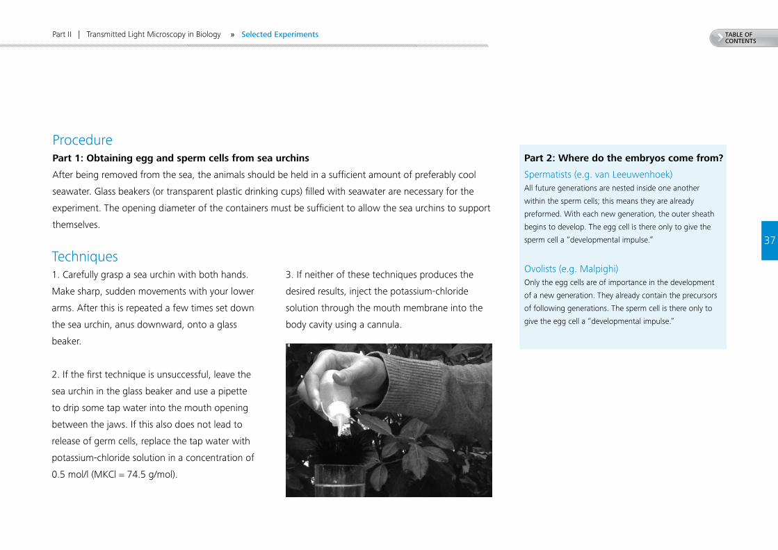
Techniques1. Carefully grasp a sea urchin with both hands.
Make sharp, sudden movements with your lower
arms. After this is repeated a few times set down
the sea urchin, anus downward, onto a glass
beaker.
2. If the first technique is unsuccessful, leave the
sea urchin in the glass beaker and use a pipette
to drip some tap water into the mouth opening
between the jaws. If this also does not lead to
release of germ cells, replace the tap water with
potassium-chloride solution in a concentration of
0.5 mol/l (MKCl = 74.5 g/mol).
3. If neither of these techniques produces the
desired results, inject the potassium-chloride
solution through the mouth membrane into the
body cavity using a cannula.
Part 2: Where do the embryos come from?
Spermatists (e.g. van Leeuwenhoek)All future generations are nested inside one another
within the sperm cells; this means they are already
preformed. With each new generation, the outer sheath
begins to develop. The egg cell is there only to give the
sperm cell a “developmental impulse.”
Ovolists (e.g. Malpighi) Only the egg cells are of importance in the development
of a new generation. They already contain the precursors
of following generations. The sperm cell is there only to
give the egg cell a “developmental impulse.”
» Selected Experiments
38
TABLE OF CONTENTS
Part II | Transmitted Light Microscopy in Biology
Work with the two historical schools of thought
(spermatists vs. ovolists) offers a good opportunity
to practice with students some important building
blocks in the attaining of scientific knowledge. This
example involves the need for control experiments
and the refutability of statements. The students will
typically select the fusion of egg and sperm cells as
an experiment with which to refute both schools
of thought. However, they overlook the approach
of performing two control experiments (only egg
cells and only sperm cells). The trainer should
provide suitable impulses to do so. The control
experiments demonstrate that one type of cell
alone is insufficient for development to occur. But
they do not exclude the possibility that the poten-
tial for development could be present in only one
of the cell types. At second glance, then, refuting
the old schools of thought remains problematic.
Could the counterpart of the second germ cell not
simply provide a stimulus (for example by emitting
a chemical substance) for the development process
which is laid down only in the second type of cell?
Clear refutation is a challenging task. At this
point, if the students do not initiate this them-
selves, the trainer should stimulate and conduct
discussion in small groups. For example, a few
students could be charged with defending the
schools of thought to be refuted.
Make certain during this process to require clear
recording and documentation (for example in
the form of drawings of some of the multicellular
stages indicating the time elapsed). The fertiliza-
tion experiments are evaluated with the aid of
microscopic observations. This allows observation
of the formation of a fertilization membrane and
the movement of the male prenucleus or the
karyogamy.
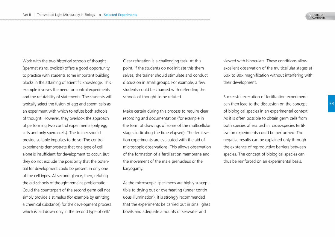
As the microscopic specimens are highly suscep-
tible to drying out or overheating (under contin-
uous illumination), it is strongly recommended
that the experiments be carried out in small glass
bowls and adequate amounts of seawater and
viewed with binoculars. These conditions allow
excellent observation of the multicellular stages at
60× to 80× magnification without interfering with
their development.
Successful execution of fertilization experiments
can then lead to the discussion on the concept
of biological species in an experimental context.
As it is often possible to obtain germ cells from
both species of sea urchin, cross-species fertil-
ization experiments could be performed. The
negative results can be explained only through
the existence of reproductive barriers between
species. The concept of biological species can
thus be reinforced on an experimental basis.
» Selected Experiments
39
TABLE OF CONTENTS
Part II | Transmitted Light Microscopy in Biology
Tasks1. Obtain adequate numbers of egg cells and
sperm cells from the species black sea urchin
(Arbacia lixula) and purple sea urchin (Paracen-
trotus lividus). Note: The samples obtained must
be clean and be supplied with adequate amounts
of fresh water. Ensure that no “foreign” cells
are carried over from other samples (by using the
same pipette, for example).
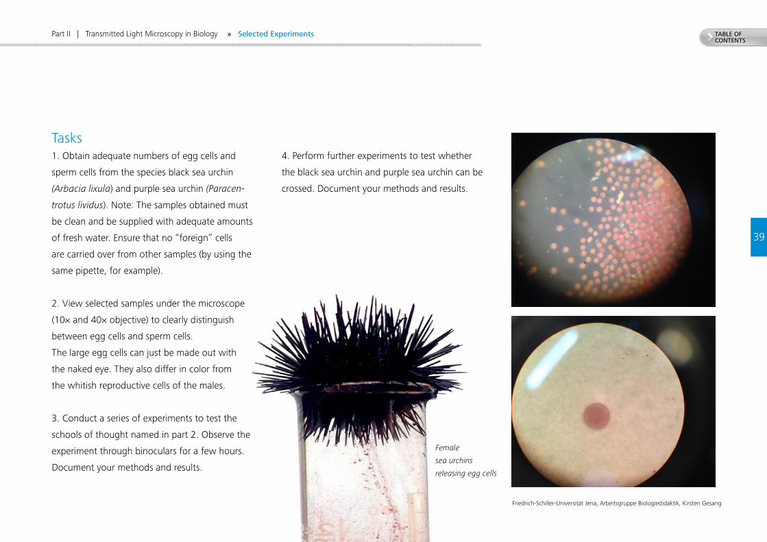
2. View selected samples under the microscope
(10× and 40× objective) to clearly distinguish
between egg cells and sperm cells.
The large egg cells can just be made out with
the naked eye. They also differ in color from
the whitish reproductive cells of the males.
3. Conduct a series of experiments to test the
schools of thought named in part 2. Observe the
experiment through binoculars for a few hours.
Document your methods and results.
4. Perform further experiments to test whether
the black sea urchin and purple sea urchin can be
crossed. Document your methods and results.
Female
sea urchins
releasing egg cells
Friedrich-Schiller-Universität Jena, Arbeitsgruppe Biologiedidaktik, Kirsten Gesang
» Selected Experiments
40
TABLE OF CONTENTS
Experiment 2
Part II | Transmitted Light Microscopy in Biology
Dry Specimens of Insects10
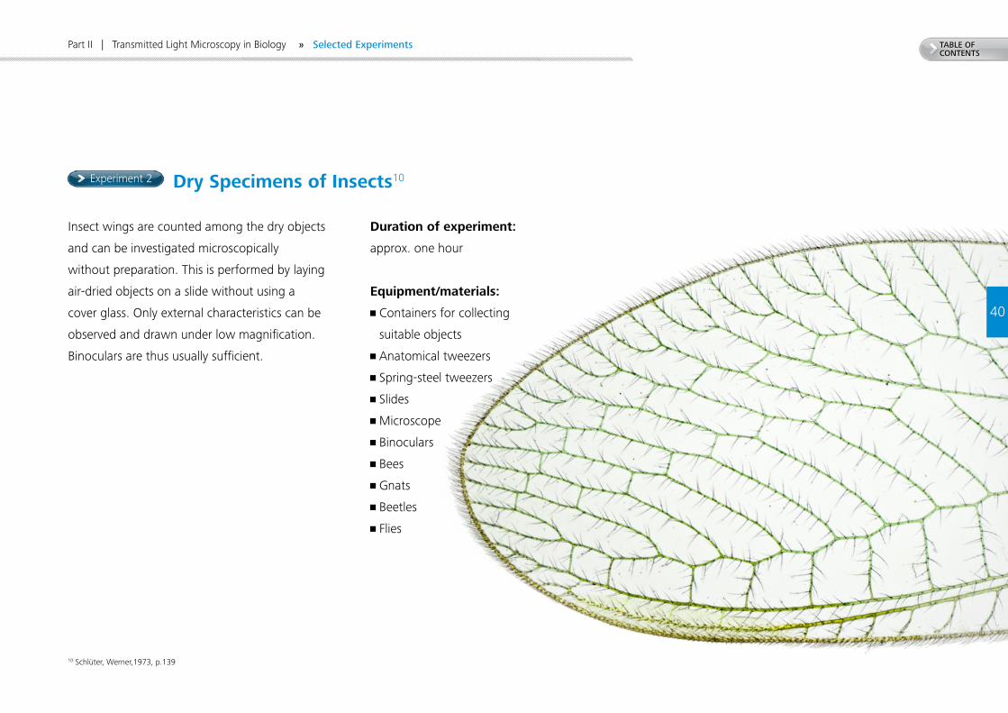
Insect wings are counted among the dry objects
and can be investigated microscopically
without preparation. This is performed by laying
air-dried objects on a slide without using a
cover glass. Only external characteristics can be
observed and drawn under low magnification.
Binoculars are thus usually sufficient.
Duration of experiment:
approx. one hour
Equipment/materials:
• Containers for collecting
suitable objects
• Anatomical tweezers
• Spring-steel tweezers
• Slides
• Microscope
• Binoculars
• Bees
• Gnats
• Beetles
• Flies
10 Schlüter, Werner,1973, p.139
» Selected Experiments
41
TABLE OF CONTENTS
Part II | Transmitted Light Microscopy in Biology
ProcedureFirst, dead insects are collected. This task can be given to the students as homework or be done inside or outside the school just before work with the microscopes
begins. Most suitable are flies, bees, beetles, and gnats. The first step is to observe the objects without a microscope and to correlate the terms with the relevant
images. As gnats are particularly easy to find, the second part of the experiment focuses on this family. Particular emphasis is placed on preparing a microscopic
drawing of the two types of wing.
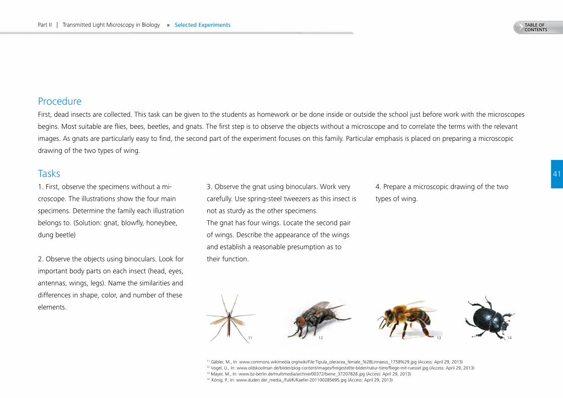
Tasks1. First, observe the specimens without a mi-
croscope. The illustrations show the four main
specimens. Determine the family each illustration
belongs to. (Solution: gnat, blowfly, honeybee,
dung beetle)
2. Observe the objects using binoculars. Look for
important body parts on each insect (head, eyes,
antennas, wings, legs). Name the similarities and
differences in shape, color, and number of these
elements.
3. Observe the gnat using binoculars. Work very
carefully. Use spring-steel tweezers as this insect is
not as sturdy as the other specimens.
The gnat has four wings. Locate the second pair
of wings. Describe the appearance of the wings
and establish a reasonable presumption as to
their function.
4. Prepare a microscopic drawing of the two
types of wing.
11 Gäbler, M., In: www.commons.wikimedia.org/wiki/File:Tipula_oleracea_female_%28Linnaeus_1758%29.jpg (Access: April 29, 2013)12 Vogel, U., In: www.oldskoolman.de/bilder/plog-content/images/freigestellte-bilder/natur-tiere/fliege-mit-ruessel.jpg (Access: April 29, 2013)13 Mayer, M., In: www.bz-berlin.de/multimedia/archive/00372/biene_37207828.jpg (Access: April 29, 2013)14 König, P., In: www.duden.de/_media_/full/K/Kaefer-201100285695.jpg (Access: April 29, 2013)
11 12 13 14
» Selected Experiments
42
TABLE OF CONTENTS
Experiment 3
Part II | Transmitted Light Microscopy in Biology
Insect Leg Types15
The extremities of insects can vary considerably in appearance. Phylogenetically, these emerged as
biramous legs providing locomotion on solid ground. Each of these legs consists of various members
(coxa, trochanter, femur, tibia, tarsus). The aim of this experiment is to observe different types of leg.
It is intended to demonstrate that the basic structure of the legs is the same even though they differ in
function and shape.
ProcedureBefore the experiment begins, dead insects are collected as in experiment 2. Most suitable are various
types of beetle, cockroaches, grasshoppers, bees, and flies. The objects collected are observed at low
magnification using binoculars. The main emphasis is on the structure of the legs. These may be detached
from the insect if necessary to facilitate observation.
The tasks present the basic structure of an insect leg which is then detected and carried over to the vari-
ous leg types. Finally, the correlation is drawn between the structure and function of each type of leg and
described in the students’ notebook.
Duration of experiment: approx. one hour
Equipment / materials:
• Glass containers
• Small glass bowls
• Spring-steel tweezers
• Binoculars
• Various insects
• Five colored pencils
15 Schlüter, Werner, 1973, pp. 253 ff.
» Selected Experiments
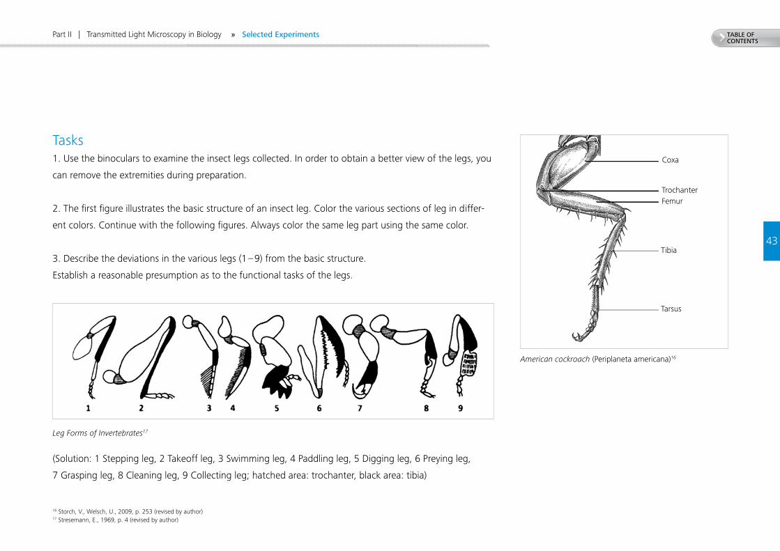
American cockroach (Periplaneta americana)16
43
TABLE OF CONTENTS
Coxa
TrochanterFemur
Tibia
Tarsus
Part II | Transmitted Light Microscopy in Biology
Tasks1. Use the binoculars to examine the insect legs collected. In order to obtain a better view of the legs, you
can remove the extremities during preparation.
2. The first figure illustrates the basic structure of an insect leg. Color the various sections of leg in differ-
ent colors. Continue with the following figures. Always color the same leg part using the same color.
3. Describe the deviations in the various legs (1 – 9) from the basic structure.
Establish a reasonable presumption as to the functional tasks of the legs.
Leg Forms of Invertebrates17
(Solution: 1 Stepping leg, 2 Takeoff leg, 3 Swimming leg, 4 Paddling leg, 5 Digging leg, 6 Preying leg,
7 Grasping leg, 8 Cleaning leg, 9 Collecting leg; hatched area: trochanter, black area: tibia)
16 Storch, V., Welsch, U., 2009, p. 253 (revised by author) 17 Stresemann, E., 1969, p. 4 (revised by author)
» Selected Experiments
44
TABLE OF CONTENTS
Experiment 4
Part II | Transmitted Light Microscopy in Biology
Onion Cells and Their Component Parts18
The cellular structure of plants is demonstrated using easy-to-obtain objects. This involves investigating the
most important cell organelles: cell wall, cytoplasm, mitochondria, and cell vacuole.
To illustrate specific cell organelles, it is necessary to apply a microscopic staining technique which affects
the microscopic object. This effect can lead to alterations (artefacts) which are not present in living cells.
ProcedureFirst, cut the onion in four pieces and remove one scale of the onion. Now, use a razor blade to cut a
square in the convex surface of the onion and peel off a piece of skin using the tweezers. Place this in
a water drop on the slide and cover it with a cover glass. Now, observe the specimen under lowest
magnification. For further observations, 100× magnification is suitable. Small air bubbles are often present
on parts of the onionskin. These should also be examined in order to avoid confusing these with cell
organelles later.
Of the cells in the onion, only the cell walls are clearly visible. The other cell organelles have the same
index of refraction as the water in which the cells are being examined. These are only vaguely visible due
to the lack of contrast and can be stained by means of various techniques.
In this experiment, methylene blue, eosin, and neutral-red solution are used. The cell components treated
with these stains are compared to one another.
Duration of experiment: approx. one hour
Equipment / materials:
• Microscope
• Simple phase-contrast setup
• Slides
• Cover glasses
• Tweezers
• Razor blade
• Lancet needle
• Pipette with bulb
• Square glass bowls
• Three staining vials
• Distilled water
• 0.1% aqueous methylene-blue solution (Xn)
• Neutral red
• Eosin
• Sugar
• Onion
18 Friedrich-Schiller-Universität Jena, Arbeitsgruppe Biologiedidaktik, 2011, p. 22
» Selected Experiments
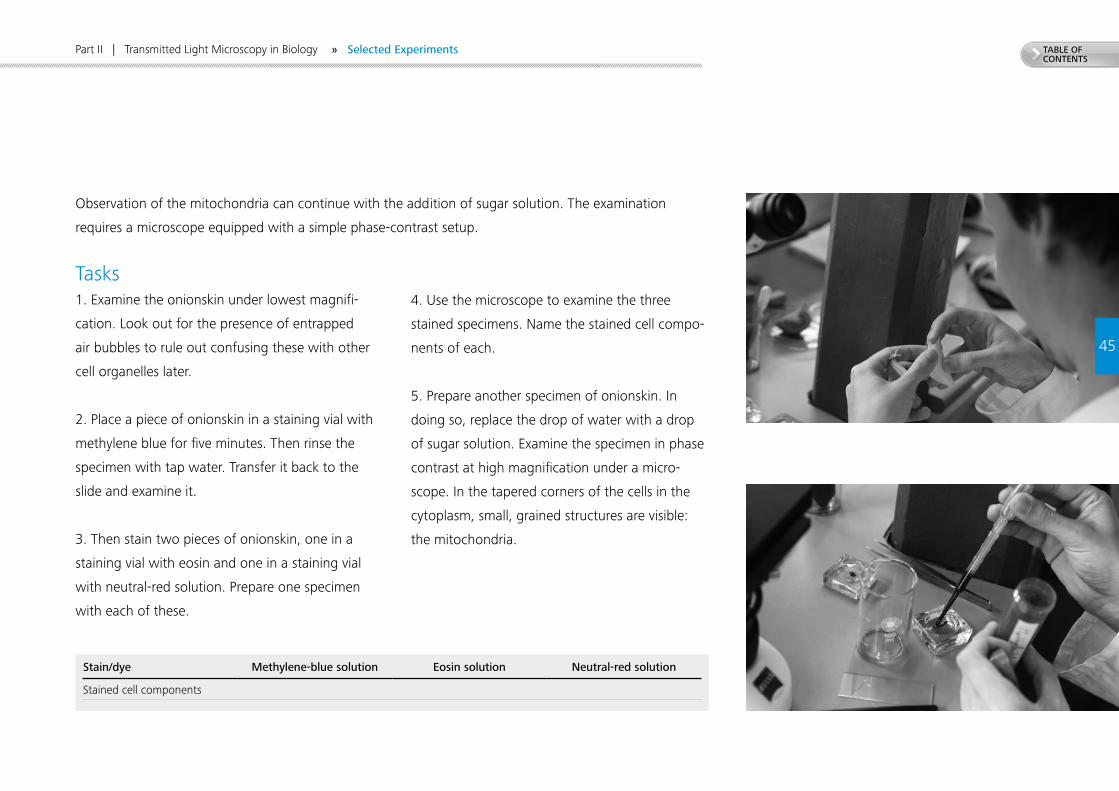
TABLE OF CONTENTS
45
Part II | Transmitted Light Microscopy in Biology
Tasks1. Examine the onionskin under lowest magnifi-
cation. Look out for the presence of entrapped
air bubbles to rule out confusing these with other
cell organelles later.
2. Place a piece of onionskin in a staining vial with
methylene blue for five minutes. Then rinse the
specimen with tap water. Transfer it back to the
slide and examine it.
3. Then stain two pieces of onionskin, one in a
staining vial with eosin and one in a staining vial
with neutral-red solution. Prepare one specimen
with each of these.
4. Use the microscope to examine the three
stained specimens. Name the stained cell compo-
nents of each.
5. Prepare another specimen of onionskin. In
doing so, replace the drop of water with a drop
of sugar solution. Examine the specimen in phase
contrast at high magnification under a micro-
scope. In the tapered corners of the cells in the
cytoplasm, small, grained structures are visible:
the mitochondria.
Stain/dye Methylene-blue solution Eosin solution Neutral-red solution
Stained cell components
» Selected Experiments
Observation of the mitochondria can continue with the addition of sugar solution. The examination
requires a microscope equipped with a simple phase-contrast setup.
46
TABLE OF CONTENTS
Experiment 5
Part II | Transmitted Light Microscopy in Biology
Duration of experiment: approx. 30 minutes
Equipment / materials:
• Microscope
• Slides
• Cover glasses
• Tweezers
• Lancet needle
• Pipette with bulb
• Distilled water
• Waterweed (Elódea MICHX.)
Chloroplasts in Waterweed19
Using the waterweed (Elódea MICHX.)20 as specimen, it is very easy to examine chloroplasts under the
microscope. These cell organelles form the center of photosynthesis and contain the green pigment
chlorophyll. After a short time, the chloroplasts also begin to move, which is easy to observe.
ProcedureThis experiment deals with chloroplasts and the movement of chloroplasts. In general, any green plant
parts can be used for this experiment, but the waterweed is particularly well-suited for examination.
At suitable magnification, the chloroplasts and their movement can be observed.
TasksTransfer a waterweed leaf onto a slide. Add a drop of water and cover the leaf with a cover glass.
Under low magnification, find the midvein of the leaf and then focus on the long cells under higher
magnification.
The green oval bodies in the cytoplasm are chloroplasts. Normally, the chloroplasts move after a short
time. In the case of older leaves and of plants that have been held under unfavorable conditions,
movement begins much sooner than it does in strong, healthy plants.
19 Friedrich-Schiller-Universität Jena, Arbeitsgruppe Biologiedidaktik, 2011, p. 2220 Rothmaler, W., 1972, p. 464
» Selected Experiments
47
TABLE OF CONTENTS
Experiment 6
Part II | Transmitted Light Microscopy in Biology
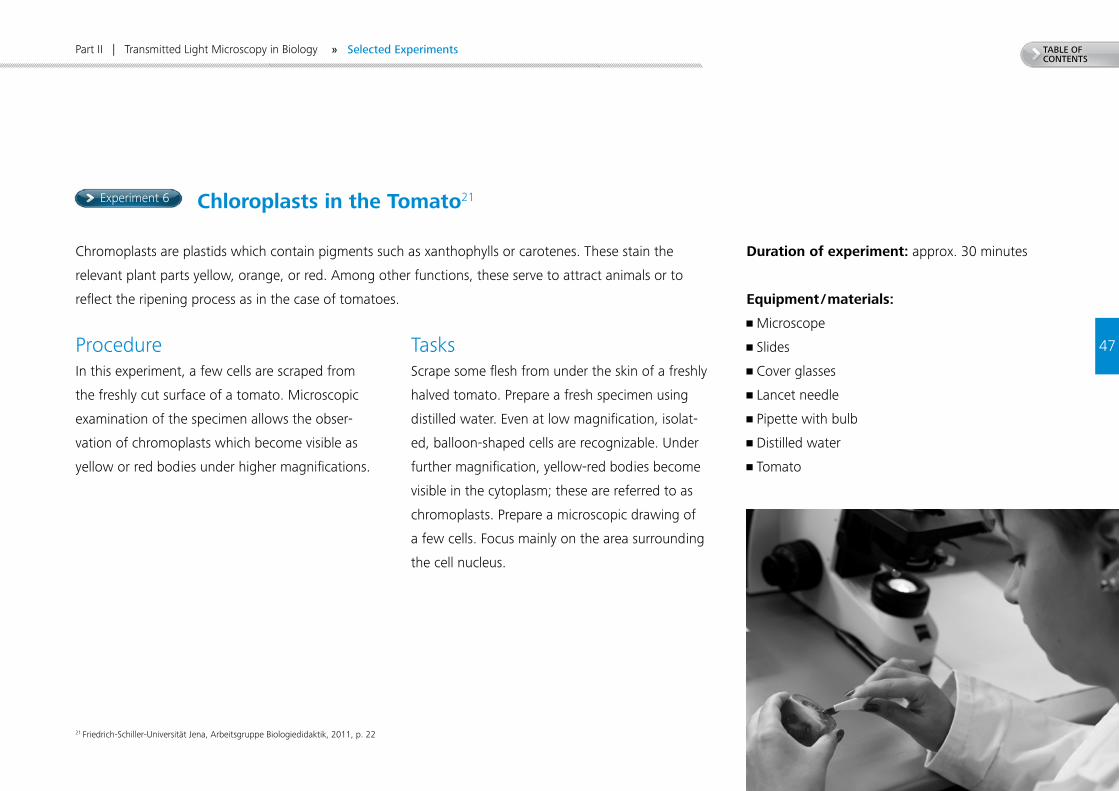
Chromoplasts are plastids which contain pigments such as xanthophylls or carotenes. These stain the
relevant plant parts yellow, orange, or red. Among other functions, these serve to attract animals or to
reflect the ripening process as in the case of tomatoes.
Duration of experiment: approx. 30 minutes
Equipment / materials:
• Microscope
• Slides
• Cover glasses
• Lancet needle
• Pipette with bulb
• Distilled water
• Tomato
ProcedureIn this experiment, a few cells are scraped from
the freshly cut surface of a tomato. Microscopic
examination of the specimen allows the obser-
vation of chromoplasts which become visible as
yellow or red bodies under higher magnifications.
TasksScrape some flesh from under the skin of a freshly
halved tomato. Prepare a fresh specimen using
distilled water. Even at low magnification, isolat-
ed, balloon-shaped cells are recognizable. Under
further magnification, yellow-red bodies become
visible in the cytoplasm; these are referred to as
chromoplasts. Prepare a microscopic drawing of
a few cells. Focus mainly on the area surrounding
the cell nucleus.
21 Friedrich-Schiller-Universität Jena, Arbeitsgruppe Biologiedidaktik, 2011, p. 22
Chloroplasts in the Tomato21
» Selected Experiments
Experiment 7
48
TABLE OF CONTENTS
Preparation of Fresh Specimens of Human and Animal Origin22
It is simple to prepare a specimen from human mucous membranes. After staining with methylene blue,
the isolated epithelial cells in the nucleus become visible. The structure of striated muscle cells can be seen
in a specimen of shredded meat fibers. The striations become even more readily visible when the specimen
is viewed under polarized light.
ProcedurePart 1: Epithelial Cells from Oral Mucous Membranes
Use the wooden tongue depressor (or the handle of a teaspoon) to scrape some mucous membranes from
the inside of your cheek. Mix this material with a little water on a slide. Now place a small drop of 0.1%
alcoholic methylene-blue solution next to the water before placing the cover glass on top. The best ob-
servation results are obtained from the cells on the diffusion boundary between the water and the methy-
lene-blue solution. This method of preparation isolates the cells from the surrounding tissue.
Duration of experiment: 30 minutes
Equipment / materials:
• Microscope
• Slides
• Cover glasses
• Polarizing filter
• Tweezers
• Two lancet needles
• Scissors
• Glass rod
• Pipettes
• Filter paper
• Wooden tongue depressor (or teaspoon)
• 0.1% alcoholic methylene-blue solution (Xn)
• 2% acetic acid (C)
• 0.9% NaCI solution
• Small piece of beef
Part II | Transmitted Light Microscopy in Biology
22 Friedrich-Schiller-Universität Jena, Arbeitsgruppe Biologiedidaktik, 2011, p. 24
» Selected Experiments
49
TABLE OF CONTENTS
Part 2: Shredded Muscle Tissue Specimen
From a piece of beef, cut a small sample along the grain. Transfer this sample to a large drop of 0.9 %
NaCl solution on the slide. Shred the meat fibers using two lancet needles until there are no raised areas
left in the specimen.
Remove the thick, opaque material from the slide and use a pipette to draw off the clouded sodium-chlo-
ride solution. Now, add fresh 0.9 % NaCl solution and place a cover glass on top. First, observe the speci-
men at 100× magnification and then at 400× to 500×. It can be seen that muscles consist of single fibers
which are formed in turn from myofibrils. The most obvious feature is the striation. This is visible because
the myofibrils are made up of alternating zones which are single and double refractive. Examine the speci-
men in polarized light. This makes the striations even more obvious.
Use a strip of filter paper to absorb the NaCl solution from under the cover glass; then use a fresh pipette
to place a drop of 2 % acetic acid next to the edge of the cover glass. Use another piece of filter paper to
draw this drop underneath the cover glass. When viewing under the microscope, look at the edge of the
muscle fibers. Several elongated to lenticular cell nuclei become visible here after the acetic acid has been
added. The striated muscle tissue is therefore made up of several cells. But no cell boundaries are visible.
Part II | Transmitted Light Microscopy in Biology
Tasks1. Examine a few isolated mouth-mucous-mem-
brane cells at high magnification and draw them.
2. First, observe the muscle fiber specimen at
100× magnification and then at 400× to 500×.
Observe the object under the microscope again
after adding 2 % acetic acid. Describe your
observations.
» Selected Experiments
CH2OH
O
O O
OH
CH2OH CH2OH
O
OOH
O O
O O OOH OH
OH
OH OH OH
Experiment 8
50
TABLE OF CONTENTS
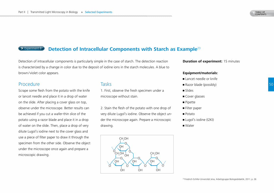
Detection of Intracellular Components with Starch as Example23
ProcedureScrape some flesh from the potato with the knife
or lancet needle and place it in a drop of water
on the slide. After placing a cover glass on top,
observe under the microscope. Better results can
be achieved if you cut a wafer-thin slice of the
potato using a razor blade and place it in a drop
of water on the slide. Then, place a drop of very
dilute Lugol’s iodine next to the cover glass and
use a piece of filter paper to draw it through the
specimen from the other side. Observe the object
under the microscope once again and prepare a
microscopic drawing.
Duration of experiment: 15 minutes
Equipment/materials:
• Lancet needle or knife
• Razor blade (possibly)
• Slides
• Cover glasses
• Pipette
• Filter paper
• Potato
• Lugol’s iodine (I2KI)
• Water
Detection of intracellular components is particularly simple in the case of starch. The detection reaction
is characterized by a change in color due to the deposit of iodine ions in the starch molecules. A blue to
brown / violet color appears.
Tasks1. First, observe the fresh specimen under a
microscope without stain.
2. Stain the flesh of the potato with one drop of
very dilute Lugol’s iodine. Observe the object un-
der the microscope again. Prepare a microscopic
drawing.
Part II | Transmitted Light Microscopy in Biology
23 Friedrich-Schiller-Universität Jena, Arbeitsgruppe Biologiedidaktik, 2011, p. 26
» Selected Experiments
Experiment 9
51
TABLE OF CONTENTS
Part II | Transmitted Light Microscopy in Biology
Paramecia24
Paramecia (Paramecium O. F. MÜLLER) belong to the ciliate group (Ciliata) and can be successfully
cultivated in an infusion of hay. Such an infusion is best made of hay from wet, swampy meadows, and
of straw and withered leaves. The dead plant material is placed in a preserving jar together with pond
water. Tap water may also be used, but this slows the development of the protozoic fauna. The infusion
should be placed near the window in a warm room. Direct sunlight should be avoided, however. After
a few days, a bacterial layer forms on the surface of the water (scum layer). Under these conditions, the
protozoa emerge from their cysts and quickly reproduce.
After about one to two weeks, paramecia and other microorganisms appear in large numbers. The tem-
porary putrid smell disappears around the third or fourth week because the water undergoes a biological
cleansing. Slowly, a natural balance is established between the number of species and the population
density. If the ciliates are needed for a longer time period, a new infusion must be set in the third week
and then inoculated with water from the existing infusion.
Duration of experiment: 30 minutes (prepara-
tions must be made one week ahead of time)
Equipment/materials:
• Preserving jars
• Slides
• Cover glasses
• Pipettes
• Pond water
• Dead plant material (hay, leaves, straw)
• Gelatine
24 Schlüter, Werner, 1973, pp. 198 ff.
» Selected Experiments
52
TABLE OF CONTENTS
Part II | Transmitted Light Microscopy in Biology
ProcedureAs described above, several hay infusions are prepared one to two weeks before the experiment is planned
to take place. Samples are taken by pipette from the scum layer, the middle layer, and the sediment of
the infusions for examination under the microscope. Pure cultures of paramecia are difficult to obtain. For
this reason, it is recommended to discuss the variety of species during microscopic examination. Frequent-
ly found species include Colpidium, Euplotes, Vorticella, Paramecium, and life-forms such as amoebas.
The paramecia are first examined live in order to observe their movement and feeding behaviors. This is
performed by placing a drop of culture liquid on a slide, placing a cover glass over it, and observing it first
at low magnification and then at higher magnification. Particularly revealing images are achieved using
darkfield and contrasting colored illumination. Gelatine can be added in order to slow down the very rapid
movement of the cilia.
Tasks1. Observe the life-forms present in the drop
of water. Prepare sketches of three individuals.
Pay particular attention to their shape.
2. Observe the movements of the paramecia.
How do they behave when they come upon an
obstacle? Describe your observations.
3. Add a drop of gelatine to the liquid being ex-
amined. The movements should now slow down.
Observe the structure of a paramecium. Prepare a
microscopic drawing.
» Selected Experiments
Barnacle/Burr
Part III
References and Notes
5454
TABLE OF CONTENTS
List of References • Friedrich-Schiller-Universität Jena, Arbeitsgruppe Biologiedidaktik, 2011. Ausgewählte Materialien
und Experimente zur Mikroskopie in der Schule, Eigenverlag, Jena.
• Berck, K.; Graf, D., 2010. Biologiedidaktik. Grundlagen und Methoden, Quelle & Meyer, Wiebelsheim.
• Gemballa, S.; Hoßfeld, U.; Bogner, W.; 2012. Woher kommen die Embryonen? In: Gemballa [ed.]:
Praxis der Naturwissenschaften. Biologie in der Schule, Aulis, Freising, Issue 4/61. Vol. 2012.
• Kluge, S.; Menzel, G., 1977. Mikrobiologie, Volk und Wissen, Berlin.
• Rothmaler, W., 1972. Exkursionsflora. Gefäßpflanzen, Volk und Wissen, Berlin.
• Schlüter, W., 1973. Mikroskopie für Lehrer und Naturfreunde. Eine Einführung in die biologische Arbeit
mit dem Mikroskop, Volk und Wissen, Berlin.
• Storch, V.; Welsch, U., 2009. Kükenthal. Zoologisches Praktikum, Spektrum, Heidelberg.
• Stresemann, E., 1969. Exkursionsfauna von Deutschland. Wirbellose II/2, Volk und Wissen, Berlin.
6. Sources
List of Illustrations• Gäbler, M., In: www.commons.wikimedia.org/wiki/File:Tipula_oleracea_female_%28Linaeus_1758%29.jpg
(Access: April 29, 2013)
• König, P., In: www.duden.de/_media_/full/K/Kaefer-201100285695.jpg (Access: April 29, 2013)
• Mayer, M., In: www.bz-berlin.de/multimedia/archive/00372/biene_37207828.jpg (Access: April 29, 2013)
• Storch, V., Welsch, U., 2009. Kükenthal. Zoologisches Praktikum, Spektrum, Heidelberg.
• Stresemann, E., 1969. Exkursionsfauna von Deutschland. Wirbellose II/2, Volk und Wissen, Berlin.
• Vogel, U., In: www.oldskoolman.de/bilder/plog-content/images/freigestellte-bilder/naturtiere/fliege-
mit-ruessel.jpg (Access: April 29, 2013)
Specimens• JOHANNES LIEDER GmbH, Ludwigsburg,
Germany, www.lieder.com
• Klaus Kemp, Somerset, England
(test slides of diatoms, www.diatoms.co.uk).
ZEISS recommends “Test slide with 8 forms.”
• Living plant material such as yeast cells,
onions Allium cepa, thick-leaved waterweed
Egeria densa, or ruffled or crinkled
Madagascar Aponogeton Aponogeton crispus,
A. longiplumulosus
www.tropica.com, www.dennerle.com
Part III | References and Notes
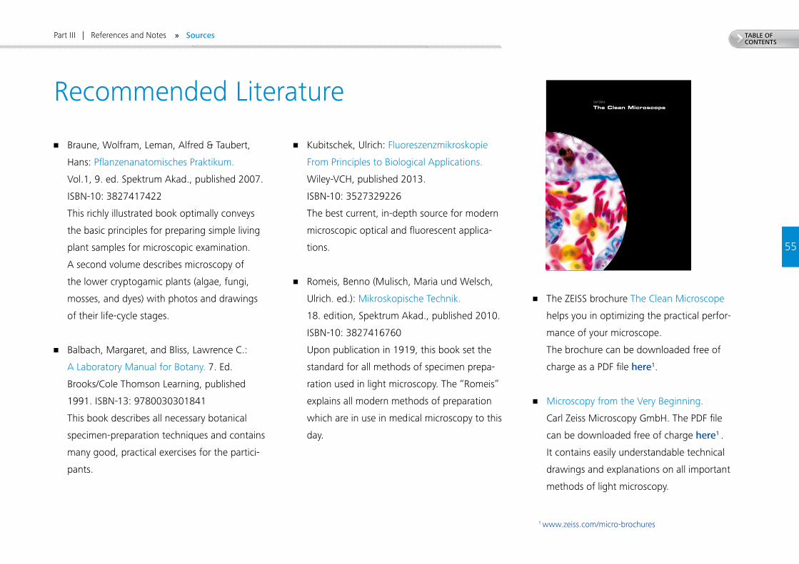
Carl Zeiss
The Clean Microscope
Met
hods
and
Prin
cipl
es
Th
e C
lean
Mic
rosc
op
e
TABLE OF CONTENTS
5555
Part III | References and Notes » Sources
• Braune, Wolfram, Leman, Alfred & Taubert,
Hans: Pflanzenanatomisches Praktikum.
Vol.1, 9. ed. Spektrum Akad., published 2007.
ISBN-10: 3827417422
This richly illustrated book optimally conveys
the basic principles for preparing simple living
plant samples for microscopic examination.
A second volume describes microscopy of
the lower cryptogamic plants (algae, fungi,
mosses, and dyes) with photos and drawings
of their life-cycle stages.
• Balbach, Margaret, and Bliss, Lawrence C.:
A Laboratory Manual for Botany. 7. Ed.
Brooks/Cole Thomson Learning, published
1991. ISBN-13: 9780030301841
This book describes all necessary botanical
specimen-preparation techniques and contains
many good, practical exercises for the partici-
pants.
• Kubitschek, Ulrich: Fluoreszenzmikroskopie
From Principles to Biological Applications.
Wiley-VCH, published 2013.
ISBN-10: 3527329226
The best current, in-depth source for modern
microscopic optical and fluorescent applica-
tions.
• Romeis, Benno (Mulisch, Maria und Welsch,
Ulrich. ed.): Mikroskopische Technik.
18. edition, Spektrum Akad., published 2010.
ISBN-10: 3827416760
Upon publication in 1919, this book set the
standard for all methods of specimen prepa-
ration used in light microscopy. The “Romeis”
explains all modern methods of preparation
which are in use in medical microscopy to this
day.
• The ZEISS brochure The Clean Microscope
helps you in optimizing the practical perfor-
mance of your microscope.
The brochure can be downloaded free of
charge as a PDF file here1.
• Microscopy from the Very Beginning.
Carl Zeiss Microscopy GmbH. The PDF file
can be downloaded free of charge here1 .
It contains easily understandable technical
drawings and explanations on all important
methods of light microscopy.
1 www.zeiss.com/micro-brochures
Recommended Literature
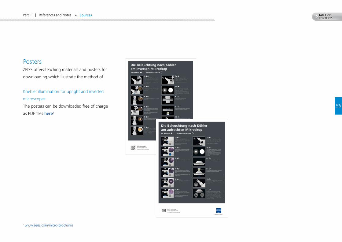
Die Beleuchtung nach Köhler am inversen Mikroskop
DE_
41_0
50_0
05 |
CZ
06-2
014
| Des
ign,
Lie
feru
mfa
ng u
nd t
echn
isch
er S
tand
kön
nen
ohne
Vor
ankü
ndig
ung
geän
dert
wer
den.
| ©
Car
l Zei
ss M
icro
scop
y G
mbH
für Hellfeld für Phasenkontrast
Kondensor auf Hellfeldposition stellen und mittels Kondensortrieb vertikal verschieben, bis eine mittlere Höheneinstellung erreicht wird.
Leuchtfeldblende und Aperturblende vollständig öffnen.
1.
Präparat mittels Fokussiertrieb scharf stellen. Fokus während der weiteren Einstellungen beibehalten.
2.
Leuchtfeldblende schließen, bis sie im Sehfeld sichtbar ist.
3.
Bild der Leuchtfeldblende durch Höhen verstellung des Kondensors mittels Kondensortrieb scharf stellen.
Der Rand der Leuchtfeldblende erscheint jetzt maximal scharf.
4.
Bild der Leuchtfeldblende mittels KondensorZentrierschrauben mittig justieren.
5.
Leuchtfeldblende jetzt so weit öffnen,bis ihr Rand gerade hinter dem Sehfeldrandverschwindet.Zum Einstellen des Phasenkontrasts bitteweiter mit Abbildung 8.
6.
Zur Einstellung der Aperturblendedas Okular aus dem Tubus entfernen undin den Tubus schauen (Hilfsmikroskopempfehlenswert).
Schließen der Aperturblende soweit…
7a.
bis sichtbare Objektivöffnung zu mindestens 2⁄3 des Durchmessers ausgeleuchtet ist. Okular wieder einsetzen.Leuchtfeldblende und Aperturblende sind bei jedem Objektivwechsel nachzujustieren.Das Mikroskop ist optimal für Hellfeld eingestellt.
7b.
Präparat auflegen und Beleuchtungeinstellen nach Schritt 1 – 6.
8.
Die dem PhasenkontrastObjektiv zugeordnete Ringblende im Kondensor auswählen.
9.
Anstelle Okular mit Hilfsmikroskop (oder Diopter) auf Phasenring im Objektiv (dunkel) und Ringblende im Kondensor (hell) scharf stellen.
10.
Zentrierschlüssel in PhZentrierlöcher des Kondensors einführen und Bild von Phasenring und Ringblende durch Drehen der Schlüssel zur Deckung bringen. Hilfsmikroskop gegen Okular austauschen. Bei jedem Objektivwechsel ist die Leuchtfeldblende nachzujustieren und ggf. die Ringblende zu wechseln. Das Mikroskop ist optimal für Phasenkontrast eingestellt.
11.
ZEISS Microscopy [email protected] www.zeiss.com/microscopy
Kondensor auf Hellfeldposition stellen und mittels Kondensortrieb in den oberen Anschlag bringen.
Leuchtfeldblende und Aperturblende vollständig öffnen.
1.
Präparat mittels Fokussiertrieb scharf stellen. Fokus während der weiteren Einstellungen beibehalten.
2.
Leuchtfeldblende schließen, bis sie im Sehfeld sichtbar ist.
3.
Bild der Leuchtfeldblende durch Absenken des Kondensors mittels Kondensortrieb scharf stellen.
Der Rand der Leuchtfeldblende erscheint jetzt maximal scharf.
4.
Bild der Leuchtfeldblende mittels Kondensor- Zentrierschrauben mittig justieren.
5.
Leuchtfeldblende jetzt so weit öffnen,bis ihr Rand gerade hinter dem Sehfeldrandverschwindet.
Zum Einstellen des Phasenkontrasts bitteweiter mit Abbildung 8.
6.
Die Beleuchtung nach Köhler am aufrechten Mikroskop
DE_
41_0
50_0
04 |
CZ
06-2
014
| Des
ign,
Lie
feru
mfa
ng u
nd t
echn
isch
er S
tand
kön
nen
ohne
Vor
ankü
ndig
ung
geän
dert
wer
den.
| ©
Car
l Zei
ss M
icro
scop
y G
mbH
für Hellfeld für Phasenkontrast
Zur Einstellung der Aperturblende das Okular aus dem Tubus entfernen und in den Tubus schauen (Hilfsmikroskop empfehlenswert).
Schließen der Aperturblende soweit…
7a.
… bis sichtbare Objektivöffnung zu mindes-tens 2⁄3 des Durchmessers ausgeleuchtet ist. Okular wieder einsetzen.Leuchtfeldblende und Aperturblende sind bei jedem Objektivwechsel nachzujustieren.Das Mikroskop ist optimal für Hellfeldeingestellt.
7b.
Präparat auflegen und Beleuchtung einstellen nach Schritt 1 – 6.
8.
Die dem Phasenkontrast-Objektiv zugeordnete Ringblende im Kondensor auswählen.
9.
Anstelle Okular mit Hilfsmikroskop (oder Diopter) auf Phasenring im Objektiv (dunkel) und Ringblende im Kondensor (hell) scharf stellen.
10.
Zentrierschlüssel in Ph-Zentrierlöcher des Kondensors einführen und Bild von Phasen-ring und Ringblende durch Drehen der Schlüssel zur Deckung bringen. Hilfsmikro-skop gegen Okular austauschen. Bei jedem Objektivwechsel ist die Leuchtfeldblende nachzujustieren und ggf. die Ringblende zu wechseln. Das Mikroskop ist optimal für Pha-senkontrast eingestellt.
11.
ZEISS Microscopy [email protected] www.zeiss.com/microscopy
5656
TABLE OF CONTENTS
PostersZEISS offers teaching materials and posters for
downloading which illustrate the method of
Koehler illumination for upright and inverted
microscopes.
The posters can be downloaded free of charge
as PDF files here1.
1 www.zeiss.com/micro-brochures
Part III | References and Notes » Sources
Carl Zeiss Microscopy GmbH 07745 Jena, Germany [email protected] www.zeiss.com/microscopy/education
In collaboration with Prof. Uwe Hoßfeld,
Heide-Lore Müller and Stephanie Wachtel,
Biology Education Research Group,
Friedrich Schiller University Jena.
Not
all
prod
ucts
are
ava
ilabl
e in
eve
ry c
ount
ry. U
se o
f pro
duct
s fo
r med
ical
dia
gnos
tic, t
hera
peut
ic o
r tre
atm
ent p
urpo
ses
may
be
limite
d by
loca
l reg
ulat
ions
.
Con
tact
you
r loc
al Z
EISS
repr
esen
tativ
e fo
r mor
e in
form
atio
n.
EN_4
1_01
1_12
1 | C
Z 09
-201
7 | D
esig
n, s
cope
of d
eliv
ery
and
tech
nica
l pro
gres
s su
bjec
t to
chan
ge w
ithou
t not
ice.
| ©
Car
l Zei
ss M
icro
scop
y G
mbH


