SECTION 27 0526 GROUNDING AND BONDING FOR COMMUNICATIONS SYSTEMS PART 1 - GENERAL 1.01 SECTION INCLUDES : A. Grounding Testing B. Exothermic Welds C. Grounding Clamps and Bushings D. Ground Lugs and Hardware E. Ground Rods and Electrodes F. Telecommunications Grounding Bus 1.02 RELATED SECTIONS : A. Section 07 8400 – Firestopping B. Section 08 3100 – Access Doors and Panels C. Section 09 6900 – Access Flooring D. Section 09 9643 – Fire Retardant Coatings E. Section 11 5200 – Audio Visual Equipment F. Section 21 0900 – Instrumentation and Control for Fire Suppression Systems G. Section 23 0900 – Instrumentation and Control for HVAC H. Section 25 0500 – Common Work Results for Integrated Automation I. Section 26 0500 – Electrical General Provisions J. Section 26 4113 – Lightning Protection Systems GROUNDING AND BONDING FOR COMMUNICATIONS SYSTEMS SECTION 27 0526 - UPDATED August 2018
Transcript
SECTION 27 0526 GROUNDING AND BONDING FOR COMMUNICATIONS SYSTEMS
PART 1 - GENERAL
1.01 SECTION INCLUDES:
A. Grounding Testing
B. Exothermic Welds
C. Grounding Clamps and Bushings
D. Ground Lugs and Hardware
E. Ground Rods and Electrodes
F. Telecommunications Grounding Bus
1.02 RELATED SECTIONS:
A. Section 07 8400 – Firestopping
B. Section 08 3100 – Access Doors and Panels
C. Section 09 6900 – Access Flooring
D. Section 09 9643 – Fire Retardant Coatings
E. Section 11 5200 – Audio Visual Equipment
F. Section 21 0900 – Instrumentation and Control for Fire Suppression Systems
G. Section 23 0900 – Instrumentation and Control for HVAC
H. Section 25 0500 – Common Work Results for Integrated Automation
I. Section 26 0500 – Electrical General Provisions
J. Section 26 4113 – Lightning Protection Systems
K. Section 26 4313 – Surge Protective Devices
L. Section 27 0502 – Required Submittals for Communications
M. Section 27 0504 – Communications Contractor Qualifications
N. Section 27 0528 – Pathways for Communications Systems
GROUNDING AND BONDING FOR COMMUNICATIONS SYSTEMS SECTION 27 0526 - UPDATED August 2018
O. Section 27 0553 – Communications Identification and Labeling
P. Section 33 8000 – Communication Utilities
1.03 REFERENCE:
A. IEEE Compliance: Comply with applicable requirements of IEEE Standard 1100 2005 pertaining to powering and grounding sensitive electronic equipment.
B. BICSI Telecommunications Distribution Methods Manual (TDMM) for the installation of data/telecommunication grounding and bonding systems.
C. NEC Compliance: Comply with NEC requirements as applicable to materials and installation of data/telecommunication grounding systems, associated equipment and wiring. Provide grounding products which are UL-listed and labeled.
D. TIA Compliance: Comply with TIA-607-C Standards.
E. UL Compliance: Comply with applicable requirements of UL Standards Nos. 467 and 869 pertaining to data/telecommunication grounding and bonding.
1.04 SYSTEM DESCRIPTION:
A. Extent of data/telecommunication grounding work is indicated by drawings and schedules. Provide all labor, materials, equipment, and services necessary for all communications, grounding and bonding.
B. Requirements of this section apply to data/telecommunication grounding work specified elsewhere in these specifications.
1.05 SUBMITTALS:
A. Submit under provisions of Section 01 3300 and/or 27 0502.
B. Product Data: Provide catalog cut sheets for all materials, equipment and components.
1.06 QUALITY ASSURANCE :
A. Manufacturers: Firms regularly engaged in manufacture of electrical connectors, terminals and fittings, of types and ratings required, and ancillary grounding materials, including stranded cable, copper braid and bus, ground rods and plate electrodes, whose products have been in satisfactory use in similar service for not less than three years.
GROUNDING AND BONDING FOR COMMUNICATIONS SYSTEMS SECTION 27 0526 - UPDATED August 2018
B. The installation of the data/telecommunication grounding system shall be performed under the direction and supervision of the Contractor's designated Project Registered Communications Distribution Designer (RCDD) under Specification 27 0504.
1.07 WARRANTY:
A. Warranty the installation to be free from inherent defects in design, workmanship and material.
1. The installation shall function properly and continually under all operating conditions required, specified or reasonably implied in the contract document.
2. Replace at no expense to the Owner, all equipment, materials or any component thereof, found defective, upon delivery or within two (2) years from date of final inspection and written acceptance by the Owner and/or Engineer.
PART 2 - PRODUCTS
2.01. Materials and Components: Except as otherwise indicated, provide data/telecommunication grounding systems indicated; with assembly of materials, including, but not limited to, cables/wires, connectors, terminals, compression lugs, grounding rods/electrodes and plate electrodes, bonding jumper braid, surge arresters, and additional accessories needed for a complete installation. Where materials or components are not indicated, provide products complying with NEC, UL, IEEE, TIA-607-C and established industry standards for applications indicated.
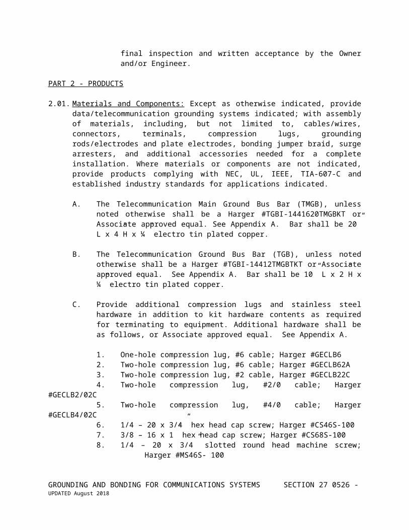
A. The Telecommunication Main Ground Bus Bar (TMGB), unless noted otherwise shall be a Harger #TGBI-1441620TMGBKT or Associate approved equal. See Appendix A. Bar shall be 20” L x 4”H x ¼” electro tin plated copper.
B. The Telecommunication Ground Bus Bar (TGB), unless noted otherwise shall be a Harger #TGBI-14412TMGBTKT or Associate approved equal. See Appendix A. Bar shall be 10” L x 2”H x ¼” electro tin plated copper.
C. Provide additional compression lugs and stainless steel hardware in addition to kit hardware contents as required for terminating to equipment. Additional hardware shall be as follows, or Associate approved equal. See Appendix A.
1. One-hole compression lug, #6 cable; Harger #GECLB62. Two-hole compression lug, #6 cable; Harger #GECLB62A3. Two-hole compression lug, #2 cable, Harger #GECLB22C4. Two-hole compression lug, #2/0 cable; Harger #GECLB2/02C5. Two-hole compression lug, #4/0 cable; Harger #GECLB4/02C6. 1/4 – 20 x 3/4” hex head cap screw; Harger #CS46S-1007. 3/8 – 16 x 1” hex head cap screw; Harger #CS68S-1008. 1/4 – 20 x 3/4” slotted round head machine screw; Harger #MS46S- 100
GROUNDING AND BONDING FOR COMMUNICATIONS SYSTEMS SECTION 27 0526 - UPDATED August 2018
9. 1/4” star washer; Harger #SW4S-10010. 3/8” star washer; Harger #SW6S-100 k.11. 1/4 – 20 hex nut; Harger #N4205-100 12. 3/8 – 16 hex nut; Harger #N6165-10013. Antioxidant joint compound, 1/2 oz. size; Harger #HCAJC1/214. Antioxidant joint compound, 8 oz. size; Harger #HCAJC815. See the Harger catalog for other appropriate stainless steel hardware and
compression lug part numbers.
D. The Horizontal Equipment Rack Ground Bus Bar, 1/4" thick x 1”H x 19”W unless noted otherwise, shall be Harger RGBH14119.25 or Associate approved equal. See Appendix A.
2.02. GROUNDING CLAMPS AND BUSHINGS:
A. Grounding clamps shall be UL Listed, with irreversible compression lug with nut, bolt and lock washer connection as manufactured by Thomas & Betts, Burndy, Harger or approved equal.
1. Setscrew type terminations are not acceptable.2. Nut, bolt and lock washer hardware shall be Type 304 stainless steel,
brass or bronze.
B. Conduit bushings shall be insulated grounding type, UL Listed, with irreversible compression lug with nut, bolt and lock washer connection as manufactured by Thomas & Betts, Burndy, O-Z Gedney or approved equal.
1. Setscrew type terminations are not acceptable.2. Nut, bolt and lock washer hardware shall be Type 304 stainless steel,
brass or bronze.
C. GROUNDING LUGS AND HARDWARE
1. Ground lugs shall be 2-hole, electroplated tinned copper, irreversible compression type, sized for the conductor and hole size and pattern, as manufactured by Harger, Panduit, Burndy, T&B, ERICO or approved equal.
2. C-Taps shall be electroplated tinned copper or aluminum, irreversible compression type as manufactured by ERICO, Panduit, Harger, T&B, Burndy or approved equal.
3. Hardware (nuts, bolts, lock washers) shall be either Type 304 stainless steel or brass/bronze alloy.
a. Lock washer shall be of the “Star Washer” type unless otherwise noted.
GROUNDING AND BONDING FOR COMMUNICATIONS SYSTEMS SECTION 27 0526 - UPDATED August 2018
b. Oxide inhibiting joint compound shall be utilized on all mechanical grounding and bonding joints and connections.
1) Synthetic base compound with suspended zinc particles for aluminum to aluminum and aluminum to copper connections.
2) Synthetic base compound with suspended copper particles for copper to copper connections.
3) Oxide inhibiting joint compound shall be as manufactured by Harger, NO-OX-ID, Penetrox/Burndy, Panduit, ERICO or approved equal.
PART 3 – EXECUTION
3.01 GROUNDING:
A. Grounding specifications for the data/telecommunication grounding system are issued in conjunction with and in addition to Electrical Grounding Specification, Section 260526. The Contractor shall furnish and install a data/telecommunication grounding system, providing a low AC impedance path to ground and a stable +0 volt to ground signal reference point for the data/communication systems equipment and infrastructures. The data/telecommunication grounding system shall comply with the TIA-607-C Commercial Building Grounding (Earthing) and Bonding Requirements for Telecommunications" and the IEEE Standard 1100-2005 "Recommended Practice for Powering and Grounding Sensitive Electronic Equipment." The data/telecommunication grounding system shall be as indicated on the detailed Engineering Drawings and documents, unless otherwise specified.
B. The data/telecommunication grounding and bonding system infrastructure shall originate with a low impedance connection to the intersystem ground bar if present or the electrical service entrance equipment (MDP) intersystem bonding termination point or ground bus, per NEC 250.94 and extend as an independent ground system throughout the building.
C. The connection to the electrical service entrance intersystem bonding termination point or ground bus shall be equal in size to the electrical service entrance ground conductor or a maximum #4/0 AWG (whichever is smaller) copper conductor to the Telecommunication Main Grounding Bus bar (TMGB), located in the telecommunication entrance facility or data/telecommunications equipment room, adjacent to the data/telecommunication service entrance equipment as required.
D. All bonding conductors and connectors shall be UL listed for the purpose intended. All bonding conductors shall be insulated stranded copper, minimum conductor size of #6 AWG, and colored green.
GROUNDING AND BONDING FOR COMMUNICATIONS SYSTEMS SECTION 27 0526 - UPDATED August 2018
E. Bonding and grounding conductors should not be placed in ferrous metallic conduit. If it is necessary to place grounding and bonding conductors in ferrous metallic conduit, the conduit shall be bonded to the grounding conductor, for conduits that exceed 3'-0" in length, the conduits shall be bonded at each end to the conductor with a #6 AWG sized copper conductor minimum.
3.02 BACKBONE:
A. A data/telecommunication grounding system backbone cable shall be provided, tying all data/communication wiring closets, cabinets, etc. to a common ground point as shown. The Telecommunication Bonding Backbone (TBB) shall be equal to the electrical service entrance ground or a minimum of a #2 AWG (whichever is larger) copper conductor unless noted otherwise.
B. The Telecommunication Bonding Backbone (TBB) shall terminate on the Telecommunication Grounding Bus bar (TGB), in the intermediate wiring closets and/or on appropriate welded ground studs/lugs in data/communication cabinets. Bonding and grounding conductors shall originate from the ground distribution bus bars, to all data/communication equipment, racks, raceways, service entrance protection, surge protection, local power distribution panels, building structural steel, etc.
C. Whenever two or more vertical Telecommunication Bonding Backbone (TBB) are required up through and within a multi-story building, the backbone cables shall be bonded together with an equivalent sized Grounding Equalizer (GE) at the top and bottom floors, and at a minimum of every third floor in between.
D. The data/telecommunication grounding system backbone cables and bonding conductors shall be installed without splices whenever possible. Where splices are necessary, they shall be minimal in quantity, accessible and located in data/telecommunication spaces only. All splices shall be approved by the Associate.
E. Where required by local code interpretation, the data/telecommunication grounding system backbone and bonding conductors shall be bare stranded copper conductor in lieu of an insulated conductor when installed in open cable trays, and/or exposed in a return air plenum space or riser rated space, Contractor to verify requirements and coordinate with the Associate.
3.03 GROUNDING AND BONDING CONNECTORS:
A. Joined segments of data/telecommunication grounding system shall be connected using only irreversible compression-type connectors, exothermic welding, bronze or stainless steel bolt, star washer and nut connections or equivalent.
B. The Contractor shall provide oxide inhibiting joint compound on all compression, nut and bolt, and mechanical type terminations.
GROUNDING AND BONDING FOR COMMUNICATIONS SYSTEMS SECTION 27 0526 - UPDATED August 2018
C. Bronze or stainless steel machine screws, nuts, bolts and star washers shall be used for all grounding hardware and fasteners.
D. Common zinc-clad or nickel-plated steel hardware fasteners are not acceptable. Replace all zinc-clad/nickel-plated hardware with specified bronze or stainless steel hardware split ring washers are not acceptable (except on the ground bus bar as part of the ground bus bar kit). The star washer to be located under the nut.
E. Setscrew type and/or box lug type terminations and split-bolt type connectors are not acceptable for the data/telecommunication grounding system, replace with irreversible compression type connectors and lugs unless otherwise noted.
F. All connections, joints and conductors shall be adequately supported and protected.
3.04 GROUND BARS AND HARDWARE:
A. All ground distribution bus bars and grounding, and bonding conductors shall be labeled and provided with a "WARNING" legend plate of engraved phenolic, green letters of 3/16" and 1/8" in height on a white background, sized 3" wide x 1-1/2" high, reading "WARNING - If connectors or cables are loose or must be removed - Please call the facility Telecommunication Manager."
B. Mechanical ground connections to trays, ladders, frames, chassis, enclosures, conduits, etc. shall be made using dedicated grounding hardware to the main equipment structure. Multi-purpose use of equipment structure hardware or attachment to equipment accessories or sub-structures (i.e. gussets, brackets, hangers, mounting brackets, etc.) is not acceptable.
C. Where indicated on the Engineering Drawings, an equipment ground bar shall be mounted on the rear side of the indicated 19” equipment racks, at the top of the rack, unless noted otherwise. All active equipment (i.e. hubs, switches, concentrators, etc.) and shielded cable grounding towers or frames, etc. on the indicated rack shall be bonded to the rack ground bar. In turn, the rack ground bar shall be bonded with a #6 ground to the “TGB/TMGB.”
D. Two (2) hole compression lugs only shall be utilized on the grounding system backbone cables where attached to the grounding system distribution bus bars, and the electrical service entrance equipment (MDP) intersystem bonding termination point or ground bus bar (#2 AWG or greater conductor).
E. Two (2) hole lugs shall be utilized when attaching an external building ground grid to the Telecommunications Main Grounding Bus bar (TMGB).
GROUNDING AND BONDING FOR COMMUNICATIONS SYSTEMS SECTION 27 0526 - UPDATED August 2018
F. Wherever possible, a two-hole compression lug shall be bolted down using two (2) bolts. When the two-hole compression lug can only utilize one-hole, always utilize the hole nearest the compression fitting, cut-off excessive tang length.
G. Items to be bonded to the data/telecommunication grounding system at the ground distribution bus bars shall include, but not be limited to the following:
1. Telephone equipment (e.g. PBX's, KSU's, ISDN equipment, etc.)2. CATV equipment3. Equipment racks and cabinets4. Cable ladders, trays and channels5. Surface mounted metallic raceways and wireways6. Metallic conduit systems7. Service entrance protected terminals8. Telecommunications and fiber optic splice enclosures9. Interbuilding cable sheaths and messengers10. Coupled bonding conductors11. Paging and access control systems
H. The positioning of ground terminators on the data/telecommunication ground bus bar shall be specific to the grounding function. Starting at one end of the ground bar, terminate across the ground bar as follows:
1. The first group on the starting end should be the branch circuit non-isolated equipment grounds.
2. All fault current dissipation paths are to be grouped next (i.e. panel grounds, feeder circuit grounds, etc.).
3. All transient sources are to be grouped next.4. The main grounding backbone (TBB) conductors are to be terminated in
the middle.5. All isolated equipment grounds are to be grouped next.6. All signal reference grounds are to be grouped at the finishing end (i.e.
dedicated grounds to cable shield grounding towers, dedicated grounds to equipment ground lugs isolated from the power cord ground pin, etc.).
3.05 GROUNDING CONDUCTORS:
A. Grounding and bonding conductors shall be provided to all individual pieces of equipment. Daisy chaining of ground bonding conductors shall be minimized and shall be limited to similar pieces or types of infrastructure elements.
B. Bonding conductors shall be provided between equipment elements in lieu of the unreliable physical electrical continuity through mounting means.
C. A bonding cable shall be lugged and connected to each section of supporting cable tray, where the cable tray utilized is not U.L. listed and/or not installed as “classified as suitable as an equipment grounding conductor.”
GROUNDING AND BONDING FOR COMMUNICATIONS SYSTEMS SECTION 27 0526 - UPDATED August 2018
D. All grounding and bonding conductors shall be insulated stranded copper, colored green or clearly marked with green tape, minimum conductor size #6 AWG. Bare copper conductor shall only be utilized when exposed in plenum or riser rated areas or buried below grade.
E. All grounding and bonding conductors shall be maintained as short and straight as possible, with the maximum radius bends practical (20x conductor dia.), in no case should the minimum bend radius be less than 10x the conductor diameter. Daisy chaining of grounding and bonding conductors shall be prohibited.
F. All grounding and bonding conductors shall be free from loops and coils (either partial or full), no bend should be greater than 90°.
G. All grounding and bonding conductors shall be protected from physical damage, the conductor shall not be run exposed across the floor or strung from item to item without intermediate support. Route grounding and bonding conductors to provide physical protection and support or route in conduit as required.
H. Grounding and bonding conductors shall be provided to all items and equipment elements in lieu of the unreliable physical mounting means for electrical continuity.
1. The utilization of conduit fittings, mounting hardware, support hardware or the attachment hardware for providing grounding and bonding in lieu of a grounding and bonding conductor is not acceptable.
3.06 GENERAL:
A. Mechanical connection points to trays, ladders, frames, chassis, enclosures, etc. shall be neatly burnished on both sides to remove the finishes and expose bare metal for a positive electrical connection.
B. A grounding bushing shall be utilized on each unbonded conduit to bond the conduit to ground, discard the setscrew type clamp provided and bolt the compression type ground lug directly to the bushing using a bronze or stainless steel machine screw and star washer.
C. Grounding bushings shall be utilized on each conduit and shall be bonded to the grounded enclosure by means of properly installed conduit nuts, one on each side of the enclosure panel and properly tightened such as to cut through the panel paint and make bare metal to metal contact.
D. Where a grounding bushing has not been installed on an existing conduit and cannot be installed due to existing installed cable base, a U.L. listed, bonding and grounding wedge shall be installed on the end of the conduit adjacent to the existing bushing fitting. Attach the compression type ground lug to the bonding and grounding wedge using a bronze or stainless steel machine screw and star washer.
GROUNDING AND BONDING FOR COMMUNICATIONS SYSTEMS SECTION 27 0526 - UPDATED August 2018
E. When an isolated external building ground grid is utilized, the ground grid shall attach to the Telecommunication Grounding Main Bus bar (TGMB) with two (2) separate (redundant) leads originating from separate ground rods. The ground grid shall attach directly to the Telecommunication Grounding System only at the main distribution bus bar (TMGB), unless noted otherwise.
F. The data/telecommunication bonding system shall be extended to and through all data/communication raceways such as cable trays, cable channels, ladder systems, metallic surface mounted raceways, etc. For raceways the bonding system shall be extended by means of extending a #6 AWG minimum bonding conductor through the length of the raceway system and lugging to each section of raceway, lugging at 8 foot maximum intervals along the length of the raceway, and lugging twice to all sections of raceway in lieu of the installation of individual bonding jumpers between each raceway section.
1. The tray or raceway shall not be utilized as the TBB.
G. AK. Where a bare copper Telecommunication Bonding Backbone (TBB) conductor or bonding conductor is routed through a cable tray system, the conductor shall be routed in CMR/CMP rated innerduct to maintain isolation from the raceway.
H. Extend bonding jumpers to all pull boxes and/or transition fittings along the raceway system. The bonding conductor shall be extended through conduit or conduits connecting sections of cable tray, channel, ladder or metallic raceway systems.
I. Unless otherwise noted, individual continuous "zone" conduits shall be bonded to ground at the "home" end, with a bonding jumper installed to and through all pull boxes. Bond at the “zone” end to building steel as available.
J. Exposed grounding and bonding conductors entering cabinets and enclosures shall be provided with a large rubber grommet or chase nipple and bushing. Install grommets or bushings as required.
3.07 SYSTEM TESTING:
A. The Contractor shall inspect and verify all the existing grounding systems to which attachments are being made, which shall include but not be limited to the following:
1. Electrical Service Entrance Grounding2. Telephone Service Entrance Grounding3. Electrical System(s) Grounding4. Structural Building Steel Grounding5. Conduit and Raceway System(s) Grounding6. Natural Gas Line Grounding
GROUNDING AND BONDING FOR COMMUNICATIONS SYSTEMS SECTION 27 0526 - 10UPDATED August 2018
7. Ground Connection to the Source Side of Water Meter and the Water Meter Bonding Jumper
8. Building Lightning Protection System (if equipped)
B. Upon completion of the installation of the data/telecommunication grounding system and/or servicing of the existing grounding systems, the Contractor shall perform approved standard ground resistance tests with an Associate approved ground resistance test unit (i.e. stakeless clamp-on ground resistance tester, two- point and three-point fall of potential tester), using approved procedures as noted in this specification.
C. "CAUTION" - Never assume a ground wire is electrically dead without first testing to be sure. Always test for and record, the voltage and ground current on the ground conductor at the test point prior to measuring ground resistance. Erroneous ground resistance measurements will result if the ground current exceeds 2 Amps AC. Contractor shall identify sources of high ground current (greater than 1 Amp AC) before proceeding with ground testing.
D. NOTE: By measuring at several points and comparing the readings, (for voltage, ground current and resistance) it is possible to identify neutral/ground loops, utility grounds and central office grounds. The tests are effective and accurate because the ground window is connected to the utility ground at only one point, according to standard practices and code. A reading of less than 0.1 Ohms generally indicates that the cable is continuous with itself, providing an acceptable ground path, which can be usually confirmed by comparatively nominal to high ground current readings. The source of a ground current may be obtained when readings are taken at multiple locations around the plane. A good low impedance ground may have very high AC ground current flow, depending upon the type of equipment being grounded.
E. The Contractor shall inspect, service and verify all of the grounding systems as per this specification section. Failures of the existing grounding systems to meet the intent of Specification Section 16450 and this section shall be brought to the attention of the Associate and Owner in writing.
F. The Contractor shall perform Telecommunication Grounding System Testing as follows:
1. Measure ground current and ground resistance readings on all Telecommunications Bonding Backbone (TBB) conductors at each “TMGB/TGB”.
2. Measure ground current and ground resistance readings on all bonding jumpers at each “TMGB/TGB”.
3. Record all readings on Test Form #1. Contractor to reproduce Test Form #1 as required.
GROUNDING AND BONDING FOR COMMUNICATIONS SYSTEMS SECTION 27 0526 - 11UPDATED August 2018
4. Where test results indicate a ground current of 1 Amp or greater, the Contractor shall take appropriate action to identify and reduce the ground current to less than 1 Amp. The Contractor shall notify the Associate in writing of the excessive ground current, the source and action taken to reduce the current.
G. The Contractor shall demonstrate by testing that the data/telecommunication grounding system to earth resistance value is 5 Ohms or less, utilizing a “clamp- on” or 3 point fall of potential tester.
H. The Contractor shall be able to demonstrate by test that the data/telecommunication grounding system resistance from any grounded non-current carry conductor in the system to the electrical service entrance neutral/ground bonding conductor is less than 0.1 Ohms.
I. The Contractor shall record the test results on Test Report Form 1 included herein, and provide a description of the testing procedures for submission to the Associate for approval.
J. Contractor shall include copies of the completed and approved test report in the cabling system instruction manuals.
3.08 EXISTING GROUNDING;
A. Existing grounding systems shall be checked, cleaned, re- tightened and/or re-made with a suitable anti-oxidant applied, as required to bring them up to code and standards. Discrepancies in existing systems shall be brought to the attention of the Associate in writing, for additional corrective action as required.
B. The Contractor shall include a written report with the system grounding Test Form #1. The written report shall detail the inspection, service required or performed and verification procedures of the existing grounding systems performed by the Contractor and shall detail the findings and any actions taken (e.g. existing #4 ground conductor from main tel-board and ground clamp removed from service side of water meter, all connections cleaned and burnished, anti-oxidant applied, reassembled and tightened).
3.09 INTERBUILDING OUTSIDE PLANT GROUNDING AND BONDING
A. Underground Ductbank and Manhole Installation:
1. Each manhole or vault with a cast iron cover and frame, and/or metallic conduits entering shall have a ground rod installed, driven through the knock-out provided in the bottom of the enclosure.
2. Bond the cast iron cover frame, metallic conduits and other metallic structures to the ground rod with a minimum #6 AWG insulated solid copper conductor. Exothermic weld the bonding conductor to the frame and ground rod.
GROUNDING AND BONDING FOR COMMUNICATIONS SYSTEMS SECTION 27 0526 - 12UPDATED August 2018
3. Provide a minimum #6 AWG copper bonding conductor through all conduits. Bond the conductor to the ground rod.
4. Bond all metallic conduits to the ground rod with a minimum #6 AWG copper bonding conductor.
5. Route the bonding conductors along the sides of the enclosure as to minimize exposure and protect from damage. Provide cable clamps to maintain support and position.
B. Aerial Installations:
1. When utilizing utility company pole lines for aerial cable installations, specifications and requirements of the utility company may supersede the requirements of the drawings and specifications herein, as applicable. In either case, the more stringent specification shall prevail.
2. Outdoor/aerial cable is not normally a self-supporting. It must be supported by a messenger wire with cable lashing unless otherwise noted.
3. Provide pole protection on non-metallic poles by means of a #6 AWG copper down conductor fastened to the pole from top to bottom. The pole grounding conductor serves as the ground path for the shield cable above and the messenger wire, and must be grounded at the pole base by means of a copperweld ground rod.
a. Down conductor spacing on leased utility pole lines shall be 0.4 kM (0.25 miles) or less.
b. Down conductor spacing on Company Owned Outside Plant (COSP) pole lines shall be 300M (1000’) OR 110M (400’) or less.
4. When metallic poles are used, the pole may serve as the down conductor if it is suitably grounded at the base and if the messenger wire and shield cable are bonded to the pole.
5. Power lines can provide shielding for the communication lines, in lieu of a shield cable above. Shield cable shall be a 3/8” diameter utility grade, galvanized, 7-strand messenger cable. Shield cable to be located 1M (3.3 feet) minimum above the data/communication cable messenger.
6. When data/communication cables are run jointly with power cables on the same pole line, the messengers should be bonded to the multi-grounded neutral. The multi-grounded neutral may be used in lieu of the earth driven ground rod and pole grounding wire, provided the installation meets requirements of the ground potential difference and ground path resistance tests. Bond all ground points to the power company multi-grounded neutral.
7. In order to meet requirements of the ground potential difference and ground path resistance tests, it may be necessary for the Contractor to install a buried counterpoise ground wire below the frost line along the length of the pole line. The counterpoise to be #6 AWG or larger bare copper conductor and should have all pole grounds and building grounds bonded to it.
GROUNDING AND BONDING FOR COMMUNICATIONS SYSTEMS SECTION 27 0526 - 13UPDATED August 2018
*** C. Tunnel System Installations:
1. Tunnel systems shall be dry and have provisions for positive drainage. Raceway in the tunnel system should be enclosed conduit or appropriate cable tray system per N.E.C. Article 318.
2. A minimum #6 AWG or larger ground conductor shall be run through the tray and bonded to the tray sections and to the grounding systems at each end.
3. Metallic conduits shall be bonded to the grounding systems at each end.4. Tunnel terminations, entrances and intersections shall be treated as
manholes, similarly bonded and grounded.5. Long tunnel segments shall have intermediate ground rod and bonding
conductors installed at a minimum of 300M (1000’) on center.
*** D. Exterior/Emergency Telephone and CCTV Camera Installations:
1. Poles and enclosures for mounting exterior emergency telephones and CCTV security cameras shall be bonded to ground by means of a ground rod and a minimum #6 AWG copper conductor.
a. The metallic pole, phone housing, camera housing, light fixture, phone instrument, camera, surge suppression and all other metallic items shall be bonded together and to the ground rod.
*** ONLY USE IF JOB CONTAINS THESE ITEMS
END OF SECTION 27 0526
GROUNDING AND BONDING FOR COMMUNICATIONS SYSTEMS SECTION 27 0526 - 14UPDATED August 2018
GROUNDING AND BONDING FOR COMMUNICATIONS SYSTEMS SECTION 27 0526 - 15UPDATED August 2018


![FlexBlend Surface-Mounted, Suspended...2020/09/29 · fi fi TYPE Imax [A] Tref [µs] Cores [-] C.Section [mm2] B-6A B-10A C-10A B-13A C-13A B-16A C-16A B-20A C-20A PSU 17,8 282 9](https://static.documents.pub/doc/80x56/60a5afab5634e5798021029c/flexblend-surface-mounted-suspended-20200929-fi-fi-type-imax-a-tref.jpg)


