7/27/2019 Microsoft Word - Section 4 http://slidepdf.com/reader/full/microsoft-word-section-4 1/26 Level I Course Manual – Section 4 Publ No 1 560 009 C 1 4. Infrared Theory Basics What will you learn • Scientific laws • Conduction, convection, radiation and blackbodies • Radiosity, transmittance and emittance • Emissivity, reflectivity and calibration Fundamentals of Infrared Sir William Herschel, in the year 1800, performed a simple but rather elegant experiment which led to the discovery of infrared radiation. Herschel was an astronomer who built his own telescopes; so he was quite familiar with optics and lenses. If you take a magnifying lens and focus the sunlight that passes through it onto a small area, that area gets hot. The light radiation is refracted and concentrated. A prism also refracts light radiation; it breaks the white light into a spectrum of colors. Herschel wondered about the nature of this radiation. In his own words he stated, “the prismatic rays might have the power of heating bodies very unequally distributed among them.” Being a scientist, he decided “it would be proper to recur to experiments.” Herschel used a piece of paperboard with a narrow slit in it to selectively sample any color of the spectrum produced by the solar radiation passing through a prism. The selected colors fell upon the blackened bulbs of thermometers and the results were recorded. According to his observations “the full red falls still short of the maximum of heat; which perhaps lies even a little beyond visible refraction.” So, the color responsible for radiant heat was not detectable by the human eye. Furthermore, it was located just beyond the red part of the visible spectrum. We know today that infrared radiation is a form of electromagnetic radiation which is longer in wavelength than visible light. Other types of electromagnetic radiation include x-rays, ultraviolet rays, radio waves, etc. Infrared radiation travels at the speed of light. Like visible radiation, it can be focused, reflected, and refracted. Electromagnetic radiation is categorized by wavelength or frequency. Broadcast radio stations are identified by their frequency, usually in kilohertz (kHz) or megahertz (MHz). Infrared detectors or systems are categorized by their wavelength. The unit of measurement used is the micrometer, or micron, (µ) which is one millionth of a meter. A system that can detect radiation in the 8 to 12 micrometer band is “longwave.” One that detects
Level I Course Manual – Section 4Publ No 1 560 009 C
1
4. Infrared Theory BasicsWhat will you learn
• Scientific laws
• Conduction, convection, radiation and blackbodies
• Radiosity, transmittance and emittance
• Emissivity, reflectivity and calibration
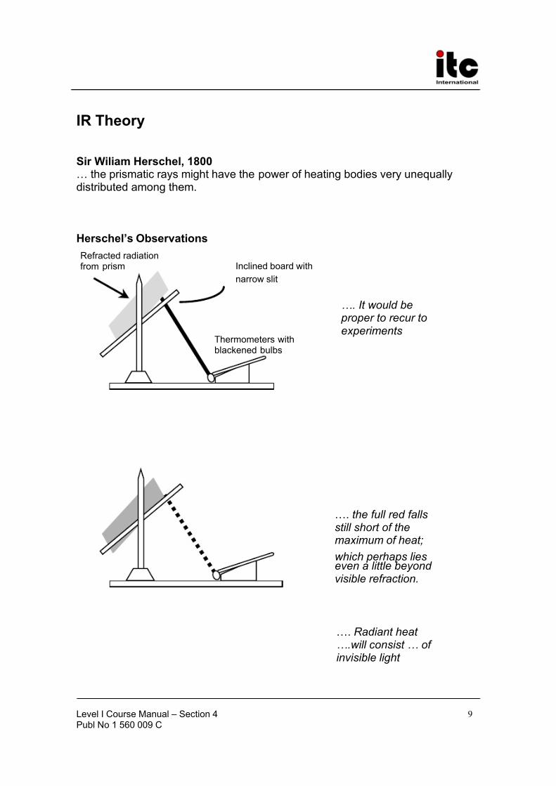
Fundamentals of InfraredSir William Herschel, in the year 1800, performed a simple but rather elegantexperiment which led to the discovery of infrared radiation.
Herschel was an astronomer who built his own telescopes; so he was quitefamiliar with optics and lenses. If you take a magnifying lens and focus thesunlight that passes through it onto a small area, that area gets hot. The lightradiation is refracted and concentrated. A prism also refracts light radiation; itbreaks the white light into a spectrum of colors. Herschel wondered about thenature of this radiation. In his own words he stated, “the prismatic rays mighthave the power of heating bodies very unequally distributed among them.”
Being a scientist, he decided “it would be proper to recur to experiments.”
Herschel used a piece of paperboard with a narrow slit in it to selectivelysample any color of the spectrum produced by the solar radiation passingthrough a prism. The selected colors fell upon the blackened bulbs of thermometers and the results were recorded. According to his observations“the full red falls still short of the maximum of heat; which perhaps lies even alittle beyond visible refraction.” So, the color responsible for radiant heat wasnot detectable by the human eye. Furthermore, it was located just beyond thered part of the visible spectrum.
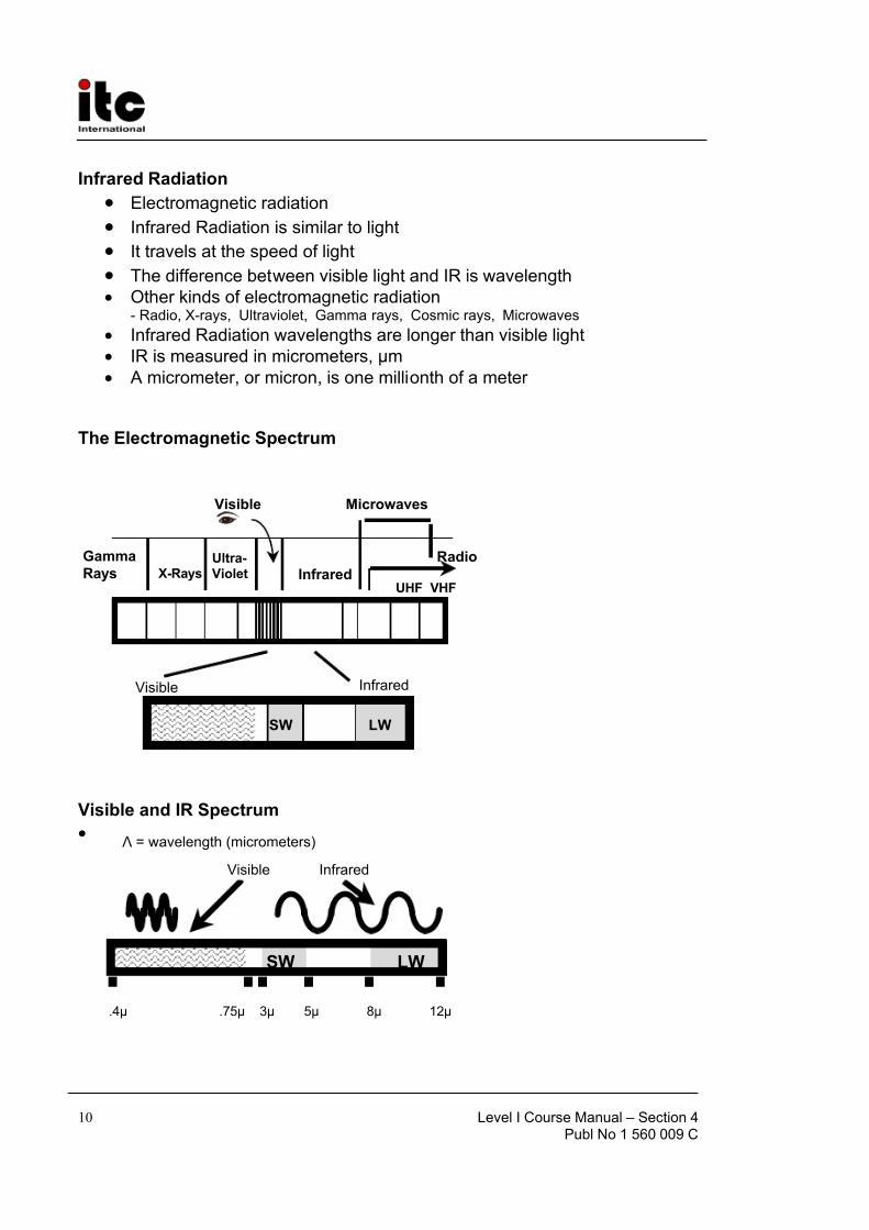
We know today that infrared radiation is a form of electromagnetic radiationwhich is longer in wavelength than visible light. Other types of electromagneticradiation include x-rays, ultraviolet rays, radio waves, etc. Infrared radiationtravels at the speed of light. Like visible radiation, it can be focused, reflected,and refracted. Electromagnetic radiation is categorized by wavelength or frequency. Broadcast radio stations are identified by their frequency, usually inkilohertz (kHz) or megahertz (MHz). Infrared detectors or systems arecategorized by their wavelength. The unit of measurement used is themicrometer, or micron, (µ) which is one millionth of a meter. A system that can
detect radiation in the 8 to 12 micrometer band is “longwave.” One that detects
Level I Course Manual – Section 4Publ No 1 560 009 C
2
radiation between 3 to 5 micrometers is “shortwave.” (A 3 to 5 system can alsobe classified as “midband,” because there are systems which can detect
radiation shorter than 3 micrometers.) The visible part of the electromagneticspectrum falls between .4 and .75 micrometers. We can see colors because wecan discriminate between different wavelengths. If you have a laser pointer youmay have noticed that the radiation is specified in nanometers; usually about650nm. If you examine a chart of the electromagnetic spectrum at 650nm (.65micrometers) you will see that it is the radiation of red light.
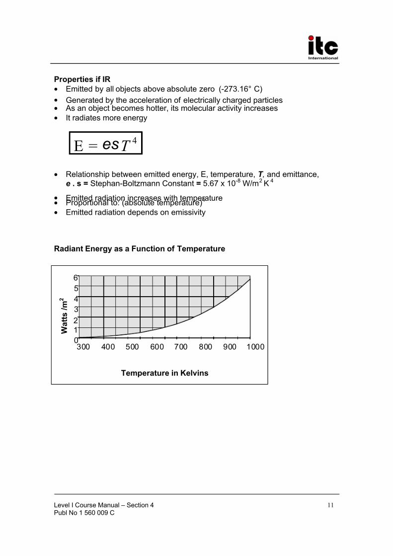
Infrared radiation is emitted by any object with a temperature above absolutezero (-273.16°C, -459.72°F). It is essentially generated by the acceleration of charged particles. Although we are speaking in terms of wavelengths, quantumtheory has shown that the energy is emitted or absorbed in the form of discrete
packages. The nature of quantum theory is a fascinating, but non-intuitivesubject, which goes beyond the scope of a level I thermography course.
As an object becomes hotter its molecular activity increases. If it gets too hot,this molecular agitation can overcome the forces binding molecules together and this breakdown can result in melting. When an object becomes warmer itemits more infrared radiation. This is the energy detected by infrared cameras.The cameras do not see temperatures or heat, they detect thermal radiation.
The amount of thermal radiation being emitted by an object can be described usingthe Stefan-Boltzmann law:
4
T E ε =
The Stefan - Boltzmann Law shows how emitted radiation, E , can vary withemissivity, ε, and temperature, T . The constant, σ, is important if you need to
quantify the radiation. Our goal here is to understand the nature of radiatingbodies. So, let’s put σ aside and concern ourselves with emissivity and
temperature. The emissivity can be considered as an efficiency factor. Theefficiency can be anywhere between 0 and 100%. The emissivity can be
anywhere between 0 and 1. The temperature can be anything within reason,but to have any meaning, an absolute scale must be used. If we assume thatthe emissivity is 1.0 and the temperature is 0°F, it would appear that there is nothermal radiation from an object at that temperature. This is certainly not thecase. Using the Kelvin scale, 0°F would be 255.22 Kelvin, a positive number.
Notice the relationship between temperature and emitted radiation. As thetemperature of an object increases, the emitted radiation from that object
Level I Course Manual – Section 4Publ No 1 560 009 C
3
increases. It is not a linear relationship. The emitted radiation is proportional tothe absolute temperature raised to the fourth power, E ~ T absolute
4. If the
temperature of an object were to double, the radiation from that object wouldnot double; it would increase by a factor of 16 (24=16).
For thermographers this means that very hot spots give off a considerableamount of infrared radiation. Again, this radiation is what the camera can see.Let’s see how the value of emissivity effects the radiation being emitted from asurface.
An object with an emissivity of 1.0 is known as a blackbody, or universalradiator. It is radiating at 100% efficiency. An object with an emissivity of .95radiates at an efficiency of 95%. A theoretical object with an emissivity of 0, has
a radiation efficiency of 0%.
Even if this object were extremely hot, according to the Stefan-Boltzmann law,there would be no radiation emitted from the surface. What do you think thisobject would look like to an infrared camera? (Assume that the object isopaque; radiation cannot pass through it.) Well, it is possible to have an objectwith an extremely low emissivity. However, the radiation that leaves the surfaceof an object is not limited to emitted radiation. Some of that radiation can bereflected. And, in some cases, radiation may pass right through the object; thisis transmitted radiation. The infrared camera always sees a true “radiation”picture. Due to emissivity, reflectivity, and transmissivity variations, when weview a thermogram, we are observing apparent temperatures. So, what would an object with an emissivity of 0 look like? It would be an infrared mirror.
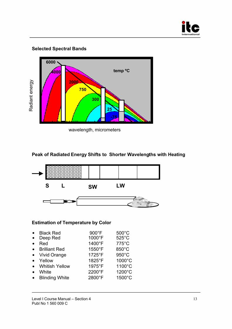
In 1900, the German Physicist Max Planck hypothesized that radiant energycan exist only in the form of discrete packages or quanta.1 This discoveryeventually led to a series of curves which characterized the spectral radiationbeing emitted from blackbodies at various temperatures; the famous BlackbodyRadiation Curves.
These curves will help you to understand the nature of thermal radiation with
respect to temperatures, camera waveband, solar radiation, etc.
One obvious observation is the fact that the hotter an object is, the moreradiation it emits. It can also be seen that the distribution of radiation getsbroader as the object gets hotter. The peak, or maximum point on the radiationcurves shifts towards the shortwave part of the spectrum with increasingtemperatures. Eventually an object can get so hot that the curve will shift intothe visible part of the electromagnetic spectrum; it will glow. If you observe the
1For an exceptionally readable account of quantum theory, I suggest George Gamow’s “Thirty Years That
Shook Physics,” a Dover Publication. For an equally readable, but more amusing approach try “QuantumTheory for Beginners” by J. P. McEvoy and Oscar Zarate.
Level I Course Manual – Section 4Publ No 1 560 009 C
4
spectrum, you will notice that this shift will enter the “red” part of the visiblespectrum first. That is why objects get “red hot.”
In some industries, temperatures of materials can be estimated by the color emitted from their surface.
Objects are classified, as following, according to their radiationcharacteristics:
• Blackbody (Universal Radiator)
• Graybody
• Realbody (Selective Radiator, Colored Body)
A blackbody is an object with an emissivity of 1.0, reflectivity of 0, and
transmissivity of 0. These values do not change with temperature, angle of observation, or wavelength. A blackbody also has an absorptivity of 1.0 Realblackbodies do not exist. No object has a reflectivity of 0. Try to imagine anobject; let’s say a cube, that is so non-reflective that you cannot discriminatecorners, faces and edges. Blackbody simulators called blackbodies which
are used for calibration of infrared cameras, have and extremely high emissivity.
A graybody is an object with an emissivity less than 1.0, remaining constantwith respect to wavelength. If you have a graybody with an emissivity of.70 inthe 3-5 micrometer waveband, it will have an emissivity of .70 in the 8-12
micrometer waveband as well.
A realbody is an object with an emissivity less than 1.0, and variable. If youhave a realbody with an emissivity of .70 in the 3-5 micrometer waveband, theemissivity in the 8-12 micrometer waveband may be higher, lower, or the same.
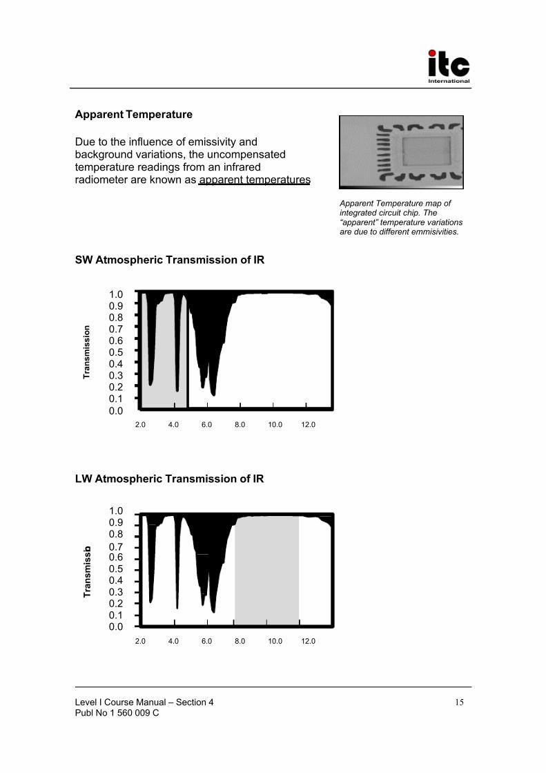
Infrared radiation passes through the atmosphere fairly well, but not perfectly.Spectral transmission curves2 of the atmosphere illustrate quite clearly thatthere are two “windows” available for transmission with a minimum amount of attenuation, or signal loss. This is the reason why commercial cameras, whichoperate in the terrestrial environment, have detectors or sensors sensitive to
radiation in the 3-5 or 8-12 micrometer waveband. In general, the 8-12 windowhas better transmission characteristics than the 3-5. In some cases, particularlywhere attenuation may lead to errors in temperature measurements,compensating factors may be used to correct for the signal loss.
When selecting an infrared camera, one must consider the spectral response of the detector Special applications may limit one’s choice. In some cases, filtersmust be used to restrict the spectral response to selective wavebands. Take,for example, plastics. If you observe a thin sheet of plastic with an infrared
2See “The Infrared Handbook,” pages 5-588 to 5-581, for a detailed graph.
Level I Course Manual – Section 4Publ No 1 560 009 C
5
camera, you will find that it has a fairly high transmissivity. This could be aproblem if your application requires you to observe thermal patterns and take
temperature measurements of this material. A spectral analysis of this materialreveals that it is essentially opaque at a waveband of 3.43 micrometers. Asolution to the problem, would be a shortwave system with a special 3.43micrometer filter. For conducting radiometric measurements of glass a 5micrometer filter can be used. Not only is glass opaque at 5 micrometers, but itthis is the waveband where it has the highest emissivity. Flame suppressionfilters can be used to see boiler tubes by narrowing the response to a regionwhere flames emit the least. This would be 3.9 micrometers for a shortwavecamera and 10.6 micrometers for a longwave system. Filters may alsoattenuate the entire bandwidth of the system to allow viewing of hotter targets.These are known as neutral density filters. Or, they may be used in a cut-on or
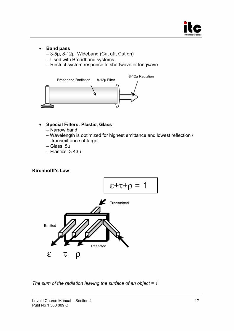
cut-off manner. Broadband systems (3-12 micrometer), for example, mayemploy filters which allow the camera to operate as a longwave or shortwavesystem.
Kirchhoff’s LawEarlier it was mentioned that the radiation leaving the surface of an object maybe emitted, reflected or transmitted. Since the sum total of this radiation mustequal 100%, we must account for all of this radiation. Mathematically, it can bestated thus:
E+R+T=1
If the object is opaque, the transmissivity, T, = 0. So the equation can besimplified:
E+R=1
The camera sees all of the radiation leaving the surface of an object; emitted,reflected and transmitted. The atmosphere, or medium through which theradiation passes, may attenuate the signal. There are many factors to consider
when taking non-contact temperature measurements.
TransmittanceIn some applications it may be necessary to view an object through an infraredwindow. A good infrared window will have high transmissivity, low emissivity,and low reflectivity.The IR Transmittance, or Transmissivity of a material is the percentage of infrared radiation that is transmitted through it.Good infrared transmitters include: germanium, NaCl (sodium chloride),diamond, vacuum, air, zinc selenide, thin plastics, and sapphire.
Level I Course Manual – Section 4Publ No 1 560 009 C
6
EmissivityEmissivity is a measure of the efficiency with which an object or surface emits
infrared radiation. Mathematically, it can be expressed as follows:
Ε Ε
=blackbody
object ε
It is the ratio of the energy emitted by an object to the energy emitted by ablackbody at the same temperature and wavelength. An object with highemissivity also has high absorptivity. For opaque objects E+R=1, thereforeE=1-R. The emittance is 1 minus the reflectance.
Some materials with fairly high emissivities include: plants, animals, people,electrical tape, asphalt, water ,non-metallic paints, rubber, soil and paper.
Reflective materials can be categorized into two groups: specular and diffuse.Specular reflectors are mirror like. They are objects that have flat smoothsurfaces, such as glass, polished metals, glazed ceramics. An object that is aspecular reflector does not necessarily have a high reflectivity. A flat sheet of Plexiglas is a specular reflector, but it is has low reflectivity. Diffuse reflectorsscatter the radiation that hits their surface. Drywall, surfaces painted with flatpaints, and paper are example of diffuse reflectors.
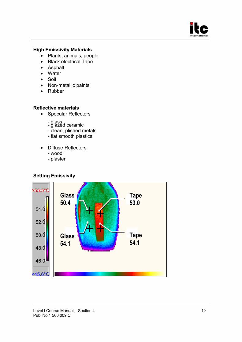
In order to make accurate temperature measurements, you must take intoaccount the emissivity of your target and the background radiation reflecting off of it. The background can be measured by aiming your camera at the source of background radiation. This measurement is taken with the emissivity of thecamera set at 1.0 If the emissivity of the target is unknown, tables can usuallyprovide a reasonably accurate value. Keep in mind, however, tables aregenerally generic. They do not take into account the specific characteristics of your instrument. To get the best values of emissivity, you can use your camerato measure the emissivity of objects. Follow this simple procedure
• Place a reference emitter on your unknown target. A piece of blackelectrical tape will do; it will have an emissivity of 0.95. Use a high qualitytape, if possible, such as 3M Scotch Super 88. Low quality tapes tend totransmit some infrared radiation in the shortwave region.
• Heat the object, or a representative sample of the object, to a temperaturewell above room temperature; an increase of about 50°F (30°C) will do. Ahot water bath with a sheet of plastic on it makes a good uniform heatsource.
• Measure the background temperature. This can be done by pointing thecamera at the background, or by using a sheet of aluminum foil as a mirror to reflect the background.
Level I Course Manual – Section 4Publ No 1 560 009 C
7
• Measure the temperature of the tape, or reference emitter, Set the emissivity(0.95 for the tape) to get a correct measurement. (This can also be done by
using a thermocouple.) Freeze and store the image, if you have thecapability. This will enable you to take readings at your convenience withoutconcern that the target will cool off.
• Now that you know the actual temperature of the sample, take atemperature measurement of the sample next to the tape, or referenceemitter.
• Adjust the emissivity until the temperature of the sample reads the same asthe temperature of the tape. This emissivity setting will be the emissivity of your sample.
Dealing with low emissivity objects
Remember, you will not get accurate temperature differences (DeltaT) or accurate temperature measurements if you do not correct for emissivity,especially with specular, highly reflective materials. A convincing, yet simpledemonstration to illustrate this can be accomplished with two sterno tins, soupcans, or similar containers. Fill one container with warm water, and the other with cool. Measure the temperature difference between the two cans on thesurface of the can. Next, measure the temperature difference of the water inthe two cans. It should be quite easy to see that one can is hotter that theother. If you try to quantify your observation, you must take into account theinfluence of emissivity and background. This demonstration may seem counter-intuitive. If both cans have the same emissivity, it would seem that their temperatures would simply read low by a certain amount; lets say twentydegrees. So, the relative temperature differences should remain the same. And, as observation reveals, that is not the case.
In dealing with low emissivity targets, here are some suggestions:
• Coat the surface of the object with a high emissivity material. Use cautionhere. Coat only enough of the surface to enable you to make accuratetemperature measurements. If you paint a low emissivity surface with flat
black paint you increase the emissivity of that surface, which is it’s ability toradiate. This could cool the surface that you are trying to measure bymeans of heat transfer: radiation.
• Take temperature measurements on corroded, rusty, dirty parts of theobject. These areas will tend to look hotter because they emit better.
• Take temperature readings from a high emissivity material in direct contactwith the object, such as the insulation on a cable.
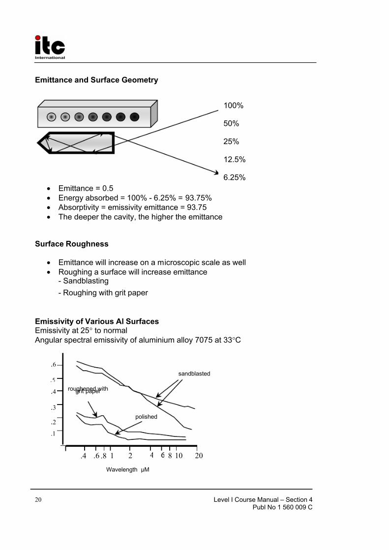
• Make the surface rough, or take temperature readings from rough areas,cavities, or corners, where geometry increases the effective emissivity.
Level I Course Manual – Section 4Publ No 1 560 009 C
15
Apparent Temperature
Due to the influence of emissivity andbackground variations, the uncompensatedtemperature readings from an infraredradiometer are known as apparent temperatures
SW Atmospheric Transmission of IR
LW Atmospheric Transmission of IR
Apparent Temperature map of integrated circuit chip. The“apparent” temperature variationsare due to different emmisivities.
Level I Course Manual – Section 4Publ No 1 560 009 C
21
Measuring Low Emittance Objects
• Coat object with high emittance material- Paint- Tape- Aquadag
• Take temperature readings rom corroded, dirty, rough areas
• Take temperature readings from high emittance object in contract withtarget
• Take advantage of surface geometry
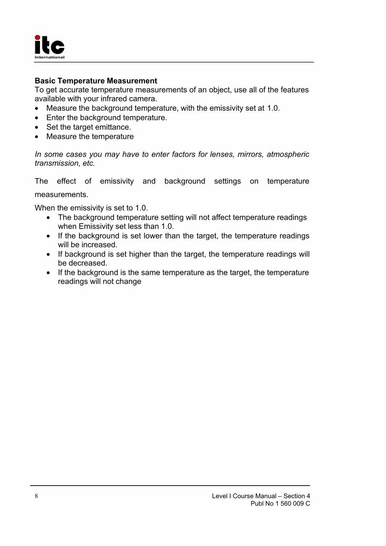
Basic Temperature Measurement – with Known Emissivity
• set the emittance to 1.00• measure the background temperature
• enter the background temperature
• set the target emittance
• measure the temperature
• When Emissivity set to 1.0 –Background temperature setting will not affect temperature readings
• When Emissivity set less than 1.0 –If background is set lower than target readings will be increased –If background is set higher than target readings will be decreased
–If background = target readings will not change
System Calibration
• Observe blackbody sources
• Generate calibration curves
• Install calibration files and test
• Once a year, the clock in the camera will trigger a maintenance due code
Level I Course Manual – Section 4Publ No 1 560 009 C
22
Emissivity and Delta Tby
Robert P. MaddingInfrared Training Center
North Billerica, MA
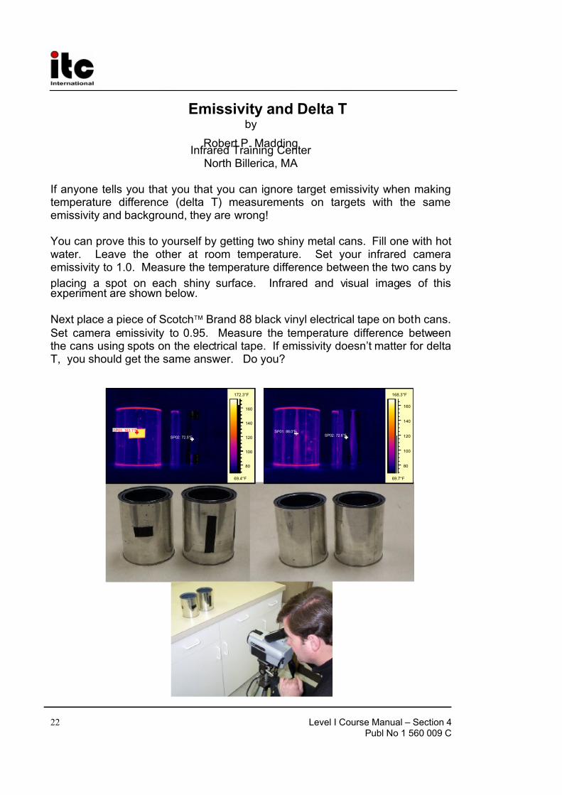
If anyone tells you that you that you can ignore target emissivity when makingtemperature difference (delta T) measurements on targets with the sameemissivity and background, they are wrong!
You can prove this to yourself by getting two shiny metal cans. Fill one with hotwater. Leave the other at room temperature. Set your infrared cameraemissivity to 1.0. Measure the temperature difference between the two cans by
placing a spot on each shiny surface. Infrared and visual images of thisexperiment are shown below.
Next place a piece of Scotch Brand 88 black vinyl electrical tape on both cans.
Set camera emissivity to 0.95. Measure the temperature difference betweenthe cans using spots on the electrical tape. If emissivity doesn’t matter for deltaT, you should get the same answer. Do you?
Level I Course Manual – Section 4Publ No 1 560 009 C
23
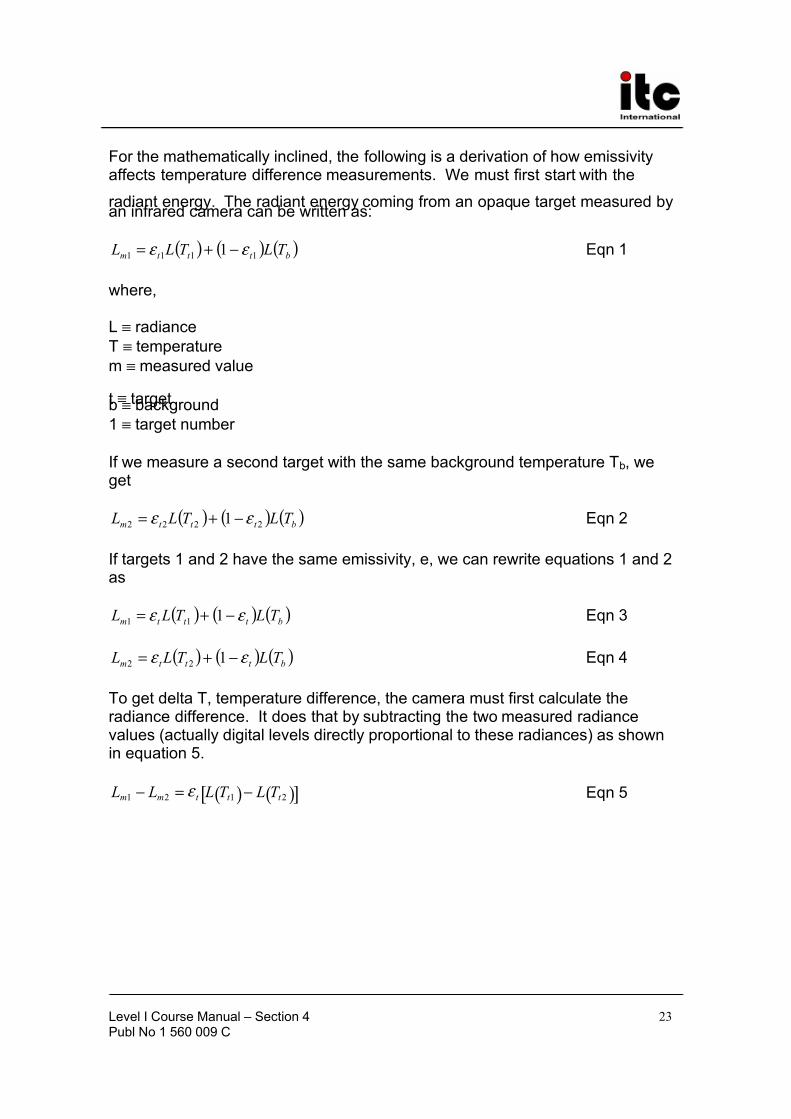
For the mathematically inclined, the following is a derivation of how emissivityaffects temperature difference measurements. We must first start with the
radiant energy. The radiant energy coming from an opaque target measured byan infrared camera can be written as:
( ) ( ) ( )bt t t m T LT L L 1111 1 ε ε −+= Eqn 1
where,
L ≡ radiance
T ≡ temperature
m ≡ measured value
t ≡ targetb ≡ background
1 ≡ target number
If we measure a second target with the same background temperature Tb, weget
( ) ( ) ( )bt t t m T LT L L 2222 1 ε ε −+= Eqn 2
If targets 1 and 2 have the same emissivity, e, we can rewrite equations 1 and 2as
( ) ( ) ( )bt t t m T LT L L ε ε −+= 111 Eqn 3
( ) ( ) ( )bt t t m T LT L L ε ε −+= 122 Eqn 4
To get delta T, temperature difference, the camera must first calculate theradiance difference. It does that by subtracting the two measured radiancevalues (actually digital levels directly proportional to these radiances) as shownin equation 5.
Level I Course Manual – Section 4Publ No 1 560 009 C
24
Note, since the emissivities are equal and the backgrounds are equal, thebackground reflection term cancels out leaving just the target radiance
difference multiplied by the target emissivity. The camera software then dividesthe measured radiance difference by the target emissivity to get the targetradiance difference as shown in equation 6.
( ) ( )[ ]
t
t t t t
T LT L L L
ε
2121
−=− Eqn 6
The camera software then finds the equivalent temperature difference in itscalibration table and displays it to the user.
It is very important to note that the target emissivity has not cancelled justbecause we made a temperature difference measurement. In fact, it appears inthe denominator of the equation. That means that the lower the emissivity thestronger will be its effect on the final result. For example, an emissivity of 0.95will scale the result by 1/0.95=1.05. This increases the result by about 5%. Anemissivity of 0.2 will scale the result by 1/0.2=5. This increases the result by500%!
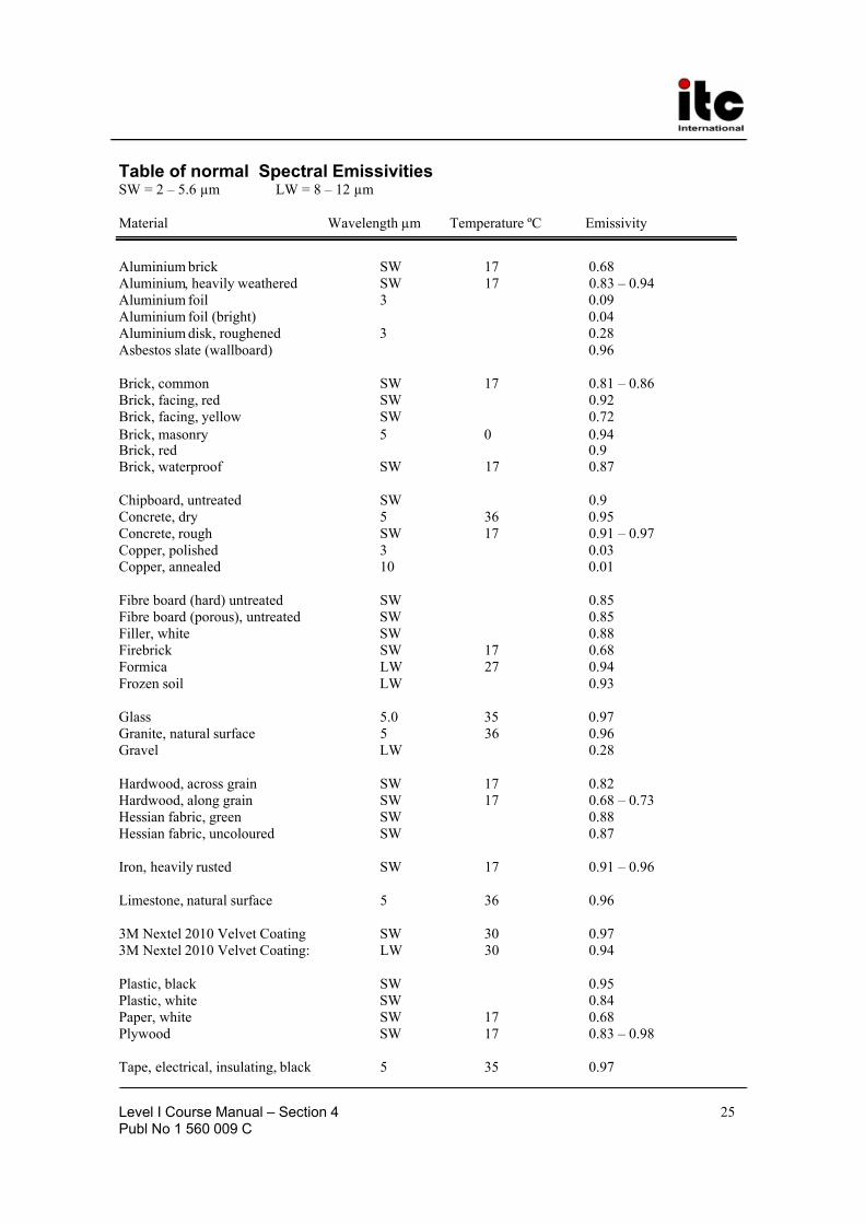
The table below is made after measurements where the wavelength band andthe temperature of the object have been know in most cases. Usually in similar tables, neither wavelength band nor temperature of the object are indicated.
Instead the words “Total normal” are mentioned. Unfortunately we think thatsuch values are not very reliable, as they take the whole spectral band,principally from 0 to infinity, into consideration. Many materials have differentemissivities in SW and LW respectively. See the chapter “Emissivity”.