TECHNICAL SPECIFICATION N ° I-ET-3010.00-1200-956-P4X-002 CLIENT: SHEET: 1 de 95 JOB: _ _ AREA: DP&T-SRGE TÍTLE: GENERAL PAINTING NP-1 ESUP MICROSOFT WORD / V. 2013 /I-ET-3010.00-1200-956-P4X-002_A2 INDEX OF REVISIONS REV. DESCRIPTION AND/OR REVISED SHEETS 0 A ORIGINAL ISSUE WHERE INDICATED. REV. 0 REV. A REV. B REV. C REV. D REV. E REV. F REV. G REV. H DATE 25/SEP/2018 07/JUN/2019 DESIGN ESUP ESUP EXECUTION MMARROIG MMARROIG CHECK FABIANA FABIANA APPROVAL JUVENTINO JUVENTINO INFORMATION IN THIS DOCUMENT IS PROPERTY OF PETROBRAS, BEING PROHIBITED OUTSIDE OF THEIR PURPOSE. FORM OWNED TO PETROBRAS N-381 REV. L PRELIMINARY
Transcript
TECHNICAL SPECIFICATION N°
I-ET-3010.00-1200-956-P4X-002
CLIENT:
SHEET: 1 de
95
JOB: _ _
AREA:
DP&T-SRGE
TÍTLE:
GENERAL PAINTING NP-1
ESUP
MICROSOFT WORD / V. 2013 /I-ET-3010.00-1200-956-P4X-002_A2
I N D E X O F R E V I S I O N S
R E V . D E S C R I P T I O N A N D / O R R E V I S E D S H E E T S
0
A
ORIGINAL ISSUE
WHERE INDICATED.
REV. 0 REV. A REV. B REV. C REV. D REV. E REV. F REV. G REV. H
DATE 25/SEP/2018 07/JUN/2019
DESIGN ESUP ESUP
EXECUTION MMARROIG MMARROIG
CHECK FABIANA FABIANA
APPROVAL JUVENTINO JUVENTINO
INFORMATION IN THIS DOCUMENT IS PROPERTY OF PETROBRAS, BEING PROHIBITED OUTSIDE OF THEIR PURPOSE.
6.5 EPOXY NOVOLAC NO VOC .......................................................................................... 31
6.6 EPOXY NOVOLAC WITHOUT SOLVENTS ENHANCED WITH GLASS FLAKES OR CERAMIC PIGMENTS .................................................................................................... 33
7 PAINT SYSTEM PRE-QUALIFICATION ....................................................................... 41
7.1 GENERAL REQUIREMENTS ......................................................................................... 41
7.2 REQUIREMENTS FOR QUALIFICATION OF HIGH PERFORMANCE COATINGS ...... 42
7.3 REQUIREMENTS FOR QUALIFICATION OF COATINGS FOR SURFACES PRESENTING PERMANENT CONDENSATION ............................................................ 43
7.4 REQUIREMENTS FOR QUALIFICATION OF COATINGS FOR BALLAST AND POTABLE TANKS .......................................................................................................... 44
7.5 REQUIREMENTS FOR QUALIFICATION OF ELETROSTATIC COATING ................... 45
8 QUALIFICATION AND CERTIFICATION ...................................................................... 46
11.1 GENERAL ...................................................................................................................... 47
11.2 PREPARATION GRADES OF WELDS, EDGES AND OTHER AREAS WITH SURFACE IMPERFECTIONS ......................................................................................... 48
18.6 MAINTENANCE PLAN ................................................................................................... 68
ANNEX A - PAINT SYSTEMS ........................................................................................... 70
ANNEX B – CHECK LIST FOR PAINT APPLICATOR EVALUATION .............................. 91
ANNEX C – QUICK TEST FOR PRESENCE OF OIL OR GREASE SURFACE CONTAMINATION ............................................................................................................. 93
ANNEX D – ALTERNATIVE THICKNESS MEASUREMENT PROCEDURE .................... 94
PRELIMIN
ARY
TECHNICAL SPECIFICATION Nº
I-ET-3010.00-1200-956-P4X-002 REV.
0
AREA:
SHEET: 5
de 95
TÍTLE:
GENERAL PAINTING NP-1
ESUP
1 INTRODUCTION
1.1 This specification covers the minimum technical requirements for the preparation of surfaces and painting of offshore structures, equipment, piping, valves, and instrumentation, to be installed on offshore production units.
1.2 The coating of bolting materials are not in the scope of this specification.
2 NORMATIVE REFERENCES
All equipment shall comply with the requirements of this technical specification, data sheets, documents as stated below and with those referred herein.
2.1 CODES AND STANDARDS
The following codes and standards include provisions which, through reference in this text, constitute provisions of this specification. The latest issue of the references shall be used unless otherwise agreed. Other recognized standards may be used, provided it can be shown that they meet or exceed the requirements of the standards referenced below.
ABNT NBR 9676 Tintas – Determinação do poder de cobertura (opacidade)
ABNT NBR 8094 Material metálico revestido e não revestido - Corrosão por exposição à névoa salina - Método de ensaio
ABNT NBR 8096 Material Metálico Revestido e Não-Revestido - Corrosão por Exposição ao Dióxido de Enxofre
ABNT NBR 15742 Tintas e Vernizes Avaliação do tempo de Vida Útil da Mistura (“pot-life”)
ABNT NBR 15877 Pintura Industrial - Ensaio de Aderência por Tração
ABNT NBR 16378 Critérios para qualificação e certificação de pintores industriais, jatistas e hidrojatistas
API RP 5L2 Recommended Practice for Internal Coating of Line Pipe for Non-Corrosive Gas Transmission Service.
ASTM A123 Standard Specification for zinc (hot-dip galvanized) coatings on iron and steel products.
ASTM A153 Standard Specification for zinc coating (hot-dip) on iron and steel hardware.
ASTM B117 Standard Practice for Operating Salt Spray (Fog) Apparatus
ASTM C868 Standard Test Method for Chemical Resistance of Protective Linings
ASTM D1141 Standard Practice for the Preparation of Substitute Ocean Water.
ASTM D1238 Standard Test Method for Melt Flow Rates of Thermoplastics by Extrusion Plastometer
ASTM D1308 Standard Test Method for Effect of Household Chemicals on Clear and Pigmented Organic Finishes
ASTM D1640 Standard Test Methods for Drying, Curing, or Film Formation of Organic Coatings
ASTM D1730 Standard Practices for Preparation of Aluminum and Aluminum-Alloy Surfaces for Painting
ASTM D2247 Standard Practice for Testing Water Resistance of Coatings in 100 % Relative Humidity
ASTM D2485 Standard Test Methods for Evaluating Coatings For High Temperature Service
ASTM D2697 Standard Test Method for Volume Nonvolatile Matter in Clear or Pigmented Coatings
ASTM D 2794 Standard Test Method for Resistance of Organic Coatings to the Effects of Rapid Deformation (Impact).
ASTM D3418 Standard Test Method for Transition Temperatures and Enthalpies of Fusion and Crystallization of Polymers by Differential Scanning Calorimetry
ASTM D4060 Standard Test Method for Abrasion Resistance of Organic Coatings by the Taber Abraser.
ASTM D4228 Standard Practice for Qualification of Coating Applicators for Application of Coatings to Steel Surfaces
ASTM D4285 Standard test method for indicating oil or water in compressed air.
ASTM D4214 Standard Test Methods for Evaluating the Degree of Chalking of Exterior Paint Films
ASTM D4400 Standard Test Method for Sag Resistance of Paints Using a Multinotch Applicator
ASTM D4518 Standard Test Method for Measuring Static Friction of Coating Surfaces.
ASTM D4541 Standard Test Method for Pull-Off Strength of Coatings Using Portable Adhesion Testers.
ASTM D4940 Standard Test method for conductimetric analysis of water soluble ionic contamination of blasting cleaning abrasives.
ASTM D522 Standard Test Methods for Mandrel Bend Test of Attached Organic Coatings
ASTM D523 Standard Test Method for Specular Gloss
ASTM D56 Standard Test Method for Flash Point by Tag Closed Cup Tester
ASTM D570 Standard Test Method for Water Absorption of Plastics
ASTM D610 Standard Practice for Evaluating Degree of Rusting on Painted Steel Surfaces
ASTM D638 Standard Test Method for Tensile Properties of Plastics
ASTM D6386 Standard practice for preparation of Zinc (Hot-Dip Galvanized) Coated Iron and Steel Product and Hardware Surfaces for Painting.
ASTM D6943 - Standard Practice for Immersion Testing of Industrial Protective Coatings and Linings
ASTM D870 Standard Practice for Testing Water Resistance of Coatings Using Water Immersion
ASTM F22 Standard Test Method for Hydrophobic Surface Films by the Water-Break Test.
ASTM D792 Standard Test Methods for Density and Specific Gravity (Relative Density) of Plastics by Displacement
ASTM G 8 Standard Test Methods for Cathodic Disbonding of Pipeline Coatings
ASTM G 154 - Standard Practice for Operating Fluorescent Ultraviolet (UV) lamp Apparatus for Exposure of Nonmetallic Materials
CSA Z245.20 - Plant-applied external coatings for steel pipe
DNVGL-RP-B401 - Cathodic protection design
DIN 55928-1 Corrosion protection of steel structures by the application of organic or metallic coatings ; general, concepts and corrosion loads
ISO 1461 Hot dip galvanized coatings on fabricated iron and steel articles - Specifications and test methods.
ISO 21809-2 Petroleum and natural gas industries - External coatings for buried or submerged pipelines used in pipeline transportation systems - Part 2: Single layer fusion-bonded epoxy coatings
ISO 2812-1 Paints and varnishes - Determination of resistance to liquids - Part 1: Immersion in liquids other than water
ISO 3233-parts 1 to 3- Paints and varnishes - Determination of the percentage volume of non-volatile matter
ISO 3679 Determination of flash no-flash and flash point - Rapid equilibrium closed cup method - Fourth Edition
ISO 4624 Paints and varnishes - Pull-off test for adhesion.
ISO 4628: Part 1 to 6 Paints and Varnishes - Evaluation of Degradation of Coatings - Designation of quantity and size of defects, and of intensity of uniform changes in appearance.
ISO 6272-1 - Paints and varnishes - Rapid-deformation (impactresistance) tests — Part 1: Falling-weight test, large-area indenter
ISO 8501: Part 1 to 3 Preparation of steel substrates before application of paints and related products. - Visual assessment of surface cleanliness.
ISO 8502: Part 2 to 6; 9; 10 Preparation of steel substrates before application of paints and related products. - Test for the assessment of surface cleanliness.
ISO 8503: Parts 4 , 5 - Preparation of steel substrates before application of paints and related products — Surface roughness characteristics of blast-cleaned steel substrates;
ISO 9514 Paints and varnishes Determination of the pot life of multicomponent coating systems Preparation and conditioning of samples and guidelines for testing
ISO 11124: Part 1 to 4 Preparation of steel substrates before application of paints and related products - Specifications for metallic blast-cleaning abrasives.
ISO 11125: Part 1 to 7 Preparation of steel substrates before application of paints and related products. Test methods for metallic blast-cleaning abrasives.
ISO 11126: Part 1 to 8 Preparation of steel substrates before application of paints and related products. Specifications for non-metallic blast-cleaning abrasives.
ISO 11127: Part 1 to 7 Preparation of steel substrates before application of paints and related products. Test methods for non-metallic blast-cleaning abrasives.
ISO 12944: Parts 1 to 9 Paints and varnishes - Corrosion protection of steel structures by protective paint systems.
ISO 17025 General requirements for the competence of testing and calibration laboratories.
ISO 17652-2 Welding - Test for Shop Primers in Relation to Welding and Allied Processes - Part 2: Welding Properties of Shop Primers.
ISO 19840 Paints and varnishes - Corrosion protection of steel structures by protective paint systems - Measurement of, and acceptance criteria for, the thickness of dry films on rough surfaces.
ISO 28199 -1 Paints and Varnishes - Evaluation of Properties of coating systems related to the application process
ISO 9227 Corrosion tests in artificial atmospheres - Salt spray tests
NACE RP0188 Discontinuity (holiday) testing of new protective coatings on conductive substrates.
NACE RP0287 Field measurement of surface profile of abrasive blast-cleaned steel surfaces using a replica tape.
NACE TM 0104 - Offshore Platform Ballast Water Tank Coating System Evaluation.
NACE TM0185 Evaluation of Internal Plastic Coatings for Corrosion Control of Tubular Goods by Autoclave Testing - Item No. 21217
NACE TM 0404 Offshore Platform Atmospheric and Splash Zone New Construction Coating System Evaluation.
NACE WJ-2 Waterjet Cleaning of Metals – Very Thorough Cleaning (WJ-2)
NHO 11 - Norma de Higiene Ocupacional - Avaliação dos níveis de iluminamento em ambientes internos de trabalho
NR 26 Sinalização de Segurança;
NR-37 Segurança e Saude em Plataformas de Petróleo.
NSF 61 Drinking water system components - Health effects
N-1993 Estruturas Oceânicas - Delimitação da Zona de Transição
RESOLUTION MSC.215(82) Performance Standard for Protective Coatings for Dedicated Seawater Ballast Tanks in All Types Of Ships and Double-Side Skin Spaces of Bulk Carriers.
SSPC QP 01 Standard Procedure for Evaluating the qualifications of Industrial/Marine Painting Contractors (Field application to complex industrialsteel structures and other metal components)
SSPC QP 03 Certification Standard for Shop Application of Complex Protective Coating Systems
SSPC SP 1 Solvent cleaning.
SSPC SP 7 Brush-off Blast Cleaning - NACE No. 4
SSPC SP 11 Power Tool Cleaning to Bare Metal.
SSPC SP 12 Surface Preparation and Cleaning of Cleaning of Metals by Waterjetting Prior to Recoating - NACE NO. 5
SSPC VIS 4 Guide and Reference Photographs for Steel Surfaces Prepared by Waterjetting - NACE VIS 7;
SSPC-TR 3/NACE 6A192 Dehumidification and temperature control during surface preparation, application, and curing for coatings/linings of steel tanks, vessels and other enclosed areas.
Governmental codes, regulations, ordinances or rules applicable to the equipment in Brazil shall prevail over the requirements of above specification, including reference codes and standards and/or these engineering specifications, only in those cases where they are more stringent.
2.2 REFERENCE DOCUMENTS
I-ET-3010.00-1200-956-P4X-003 THERMAL SPRAY COATING APPLICATION OF ALUMINUM.
I-ET-3010.00-1000-950-P4X-001 MARINE BIOFOULING
DR-ENGP-I-1.15 COLOR CODING
2.3 DEFINITIONS AND ABBREVIATIONS
2.3.1 DEFINITIONS
COAT: a continuous layer of a coating material resulting from a single application.
COATING: the liquid, liquefiable, mastic, powder or any other composition and material that after application to a substrate, is converted into a solid protective adherent film.
PAINT: the mix composed primarily of pigments dispersed in a film-former, or binder, which is either dissolved in solvent or emulsified in water to make paint fluid enough to apply by brush, roller or spray. After application of the paint in a relatively thin film, the solvent or water evaporates and the remaining film dries or cures to form a tough, adherent coat.
COATING MATERIAL: the liquid, liquefiable, mastic, powder or any other composition and material intended to be applied on a defined surface.
PAINT SYSTEM: the sum total of the coats of metal materials and/or paints or related products that are to be applied or which have been applied to a substrate to provide corrosion protection.
PAINT MANUFACTURER: the party producing and supplying the coating materials, and providing an advisory role in all processes associated with the coating project.
MATERIAL SAFETY DATA SHEET (MSDS): a document designed to provide information regarding the health and safety aspects of a coating material or thinner.
PRODUCT DATA SHEET (PDS): a document designed to provide information on a specific coating material.
STRIPE COAT: an additional coat of paint applied usually by brush on difficult-to-reach areas and on weld seams, edges, bolts, nuts, etc., to provide specified film thickness.
SUBSTRATE: the solid surface intended to be coated or lined with the specified coating system.
SUBSTRATE TEMPERATURE: is defined as:
When the internal fluid temperature is equal or higher than 60ºC, the substrate temperature shall be equal to maximum operational temperature;
When the internal fluid temperature is lower than 60ºC, the substrate temperature is controlled by atmospheric temperature and considerations shall be done about the solar and flare radiation effect on substrate temperature.
VOLATILE ORGANIC COMPOUND (VOC): any organic liquid and/ or solid that release organic vapors spontaneously at the prevailing temperature and pressure of the atmosphere with which it is in contact.
GALVANIZING: Within all documents, specifications, drawings etc., the term galvanizing and equivalent expressions are used to state that “HOT DIP GALVANIZING” shall be applied.
PAINT APPLICATOR: Company responsible for the execution of the activities related to painting.
PRELIMIN
ARY
TECHNICAL SPECIFICATION Nº
I-ET-3010.00-1200-956-P4X-002 REV.
0
AREA:
SHEET: 10
de 95
TÍTLE:
GENERAL PAINTING NP-1
ESUP
2.3.2 ABBREVIATIONS:
ADFT: Appraisal Dry Film Thickness;
CS: Carbon steel;
CUI: Corrosion under insulation;
SS: Stainless steel;
HDG: Hot dip galvanizing;
NA: Not applicable;
DFT: Dry film thickness;
VOC: Volatile organic compound;
MSDS: Material safety data sheet;
PDS: Product data sheet;
QCP: Quality control plan;
SENAI: Serviço Nacional de Aprendizagem Industrial
3 CLASSIFICATION OF ENVIRONMENTS
3.1 For offshore units the environment classification is according ISO 12944-Part 2.
3.2 Three regions are considered in offshore units:
a) Atmospheric zone: For offshore units it means those structures situated above the water;
b) Splash zone: For offshore units is means the structures that is alternately above and below the water line. For fixed offshore units this means the region alternatively wet and dry due to tide and waves. For mobile offshore units this means the boottop region;
c) Immersed zone: For offshore units this means the regions that are underwater and not subjected to wet and dry alternation.
3.3 The inferior and superior limit of splash zone region shall be determined in accordance with N-1993.
3.4 For guidance only Table 1 specifies the environment classification according ISO 12944-Part 2.
Table 1 - Environmental Classification
Region Environmental classification
Atmospheric zone CX
Splash zone Im2/ Im4
Immersed zone Im2 / Im4
PRELIMIN
ARY
TECHNICAL SPECIFICATION Nº
I-ET-3010.00-1200-956-P4X-002 REV.
0
AREA:
SHEET: 11
de 95
TÍTLE:
GENERAL PAINTING NP-1
ESUP
4 SCOPE OF COATING
4.1 SURFACES TO BE PAINTED
4.1.1 All surfaces, other than those listed below, shall be coated in accordance with this technical specification.
4.1.2 Austenitic stainless steel with service temperature over 50°C shall be coated
4.1.3 Duplex stainless steel with service temperature over 80°C shall be coated.
4.1.4 Superduplex stainless steel with service temperature over 90°C shall be coated.
4.1.5 The coating for stainless steel parts and elements shall not contain metallic zinc.
4.2 SURFACES NOT TO BE PAINTED
4.2.1 Unless otherwise specified in the Project Coating Specification, the following surfaces shall not be coated:
a) Non-insulated high Nickel alloys;
b) Non-ferrous metal surfaces (e.g. brass, copper) excluding aluminum and ABS plastic that shall be coated;
c) Pipes internal surfaces unless specified otherwise;
d) Surfaces which shall not be coated: nameplates, valve stems, shafts, mechanically finished surfaces, gauges, windows and all other regions that the paint affect the component or equipment use according to PETROBRAS;
e) Flange faces where contact with gasket occurs;
f) Hub connector seal ring contact surface;
g) Plastic coated surfaces;
h) Surfaces to be protected by wrapping;
i) Contact surfaces of assemblies to be tied together with high-strength bolts;
j) Anodes.
5 PAINTING SYSTEM REQUIREMENTS
5.1 TEMPORARY PAINTING (SHOP PRIMER)
5.1.1 Each coating material forming a paint system shall be produced by the same PAINT MANUFACTURER.
5.1.2 All promotional paint work or shop primer coats to be applied shall be compatible with the subsequent painting scheme.
5.1.3 In case the paint system is applied on a shop-primer or any other existing coating system of a different PAINT MANUFACTURER, the PAINT MANUFACTURER of the paint system shall confirm the compatibility and the durability by issuing a formal, written, document.
PRELIMIN
ARY
TECHNICAL SPECIFICATION Nº
I-ET-3010.00-1200-956-P4X-002 REV.
0
AREA:
SHEET: 12
de 95
TÍTLE:
GENERAL PAINTING NP-1
ESUP
5.1.4 Weldable shop primer may be used provided that they are in accordance with ISO 17652-2, and applicable requirements of classification society. The weld PQR shall consider the presence of shop primer.
5.1.5 Deck area may receive a specific temporary paint resistant to impact and abrasion, with objective to retain the surface preparation profile and avoid premature corrosion during construction time.
5.2 PAINT SYSTEMS
5.2.1 The paint systems described at ANNEX A are specified for each specific area to be painted at Table 2.
5.2.2 The following materials shall receive the same paint system as carbon steel: low alloy steel, nickel alloyed steel (3,5Ni, 9Ni), ferritic stainless steel, and martensitc stainless steel.
5.2.3 The following materials shall receive the same paint system as austenite stainless steel: duplex stainless steel, superduplex stainless steel.
5.2.4 Any surface or equipment not mentioned in Table 2 shall be painted with a paint system mentioned in ANNEX A.
5.2.5 PETROBRAS is responsible for the paint system selection.
5.2.6 No extra cost is due when the paint system is one of those mentioned in ANNEX A.
5.2.7 Alternative paint systems may be accepted provided that a paint system pre-qualification is performed in accordance with item 6 and previously approved by PETROBRAS.
5.2.8 Characteristics of ready products for application and of dry film are described in item 6.
PRELIMIN
ARY
TECHNICAL SPECIFICATION Nº
I-ET-3010.00-1200-956-P4X-002 REV.
0
AREA:
SHEET: 13
de 95
TÍTLE:
GENERAL PAINTING NP-1
ESUP
Table 2- Paint Systems
Nº Item Substrate
service temperature
Paint System
Carbon Steel Austenitc Stainless
steel
1 Offshore platform structure
1.1 Topside T 80ºC 2 N.A.
1.2 Splash zone T 80ºC 16 N.A
1.3 Underwater zone T 80ºC 1 (i) N.A
2 Offshore platform structure (FPSO)
2.1 Topside T 80ºC 2 N.A.
2.2 Splash zone T 80ºC 16 N.A
2.3 Underwater zone T 80ºC 1 N.A
2.4 Niche Areas T 80ºC 1 N.A
3 Deck
3.1 Deck Area T 80ºC 3 N.A.
3.2 Supply Boat Handling Area T 80ºC 9 N.A.
3.3 Vent Masts T 80ºC 2 N.A.
3.4 Lifeboat Platforms & Davits T 80ºC 3 N.A.
3.5 Offloading Platform T 80ºC 3 N.A.
4 Structure
4.1 Process Module Structures T 80ºC 2 N.A.
4.2 Deck / Skid Structures of Process Modules T 80ºC 2 N.A.
4.3 Local Equipment Rooms + Laboratory T 80ºC 2 N.A.
6.2 Flare Tower and Piping below elevation 70000 200ºC
T600ºC¹ 7
6.3 Flare Tower and Piping below elevation 70000 T 200ºC¹ 4
i Cathodic Protection without any specif paint system, only a shop primer when required to protect the steel surface during contruction. ¹ Considering the study of Flare Thermal Calculations and Gas Dispersion Analysis.
PRELIMIN
ARY
TECHNICAL SPECIFICATION Nº
I-ET-3010.00-1200-956-P4X-002 REV.
0
AREA:
SHEET: 14
de 95
TÍTLE:
GENERAL PAINTING NP-1
ESUP
TABLE 2 - Paint Systems (cont.)
Nº Item Substrate service
temperature
Paint System
Carbon Steel paint system
Stainless steel paint
system
7 Helideck
7.1 Helideck Structure T 80ºC 2 N.A.
7.2 Helideck Landing Area T 80ºC 9 13 for Al.
8 Crane
8.1 Deck Box T 80ºC 2 N.A.
8.2 Pedestal T 80ºC 2 N.A.
8.3 Crane Outside T 80ºC 2 N.A.
8.4 Crane Inside T 80ºC 8 N.A.
8.5 Crane Boom T 80ºC TSA
9 Static equipment
9.1 Un-insulated Surfaces (see item 4.1)
T 80ºC 2
80ºCT200ºC 4
200ºC T 600ºC
7
9.2 Insulated Surfaces (see item 5.4)
60ºC T 120ºC 4 or 7
120 T 200ºC 4 7
200ºC T 600ºC 7
10 Piping systems
10.1 Un-insulated Surfaces (see item 4.1)
T 80ºC 2
80ºCT200ºC 4
200ºC T500ºC 7
10.2 Insulated Surfaces (see item 5.4)
60ºC T 120ºC 4 or 7
120 T 200ºC 4 7
200ºC T 600ºC 7
10.3 Fire and Foam piping systems T 80ºC 2
10.4 HDG piping T 60ºC 5 N.A.
11 Machinery equipment’s
11.1 Un-insulated Surfaces (see item 4.1)
T 80ºC 2
80ºCT 200ºC 4
200ºC T 600ºC 7
11.2 Insulated Surfaces (see item 5.4)
60ºC T 120ºC 4 or 7
120ºC T 200ºC 4 7
200ºC T 600ºC 7
11.3 Fire Water & Jockey Pumps T 80ºC 2 N.A.
11.4 Submerged Seawater Lift Pumps (Caisson
mounted): Interior T 80ºC 8 N.A.
PRELIMIN
ARY
TECHNICAL SPECIFICATION Nº
I-ET-3010.00-1200-956-P4X-002 REV.
0
AREA:
SHEET: 15
de 95
TÍTLE:
GENERAL PAINTING NP-1
ESUP
TABLE 2 - Paint Systems (cont.)
Nº Item Substrate service
temperature
Paint System
Carbon Steel paint system
Stainless steel paint
system
12 Engine Room/ Pump Room
12.1 Floor T 80ºC 8 N.A.
12.2 Walls and Ceilings Bare Steel T 80ºC 8 N.A.
12.3 Walls and Ceilings under Insulation T 80ºC 8 N.A.
12.3 Structure below lowest Grating and
Foundations T 80ºC 2 N.A.
13 Accommodation Block
13.1 Outside Surfaces T 80ºC 2 N.A.
13.2 Funnel T 80ºC 2 N.A.
13.3 Inside Surfaces
13.3.1 Walls and ceilings covered by panels T 80ºC 6 N.A.
13.3.2 Uncovered walls and ceilings T 80ºC 8 N.A.
13.3.3 Covered floors. T 80ºC 6 N.A.
13.3.4 Covered floors in rest rooms, changing rooms,
galley, mess room and laundry T 80ºC 8 N.A.
13.3.5 Uncovered floors T 80ºC 12 N.A.
14 Ventilation Trunks
14.1 Ventilation Trunk – Interior T 80ºC 8 N.A.
14.2 Ventilation Trunk – Exterior T 80ºC 2 N.A.
14.3 Boiler Casing T 80ºC 2 N.A.
15 Tanks and Voids
15.1 Cargo Tanks Bottoms and underdeck area T 60ºC 15 N.A.
15.2 Slop Tanks T 60ºC 15 N.A.
15.3 Water Ballast Tanks T 60ºC 15 N.A.
15.4 Fresh Water Tanks(ii) T 40ºC 11
15.5 Fresh Water Tanks T 60ºC 10 N.A.
15.6 Settling Separator Tank T 80ºC 10 N.A.
15.8 Produced Water Tanks T 80ºC 10 N.A.
15.9 Void Spaces & Cofferdams T 80ºC 10 N.A.
15.10 Diesel Oil & HDO Tanks T 80ºC 10 N.A.
15.11 Fuel Oil Tanks T 80ºC 10 N.A.
15.12 Chain Lockers T 80ºC 3 N.A.
15.13 Off-spec tank T<80°C 10 N.A.
15.14 Double plate ² T<80°C 22 N.A.
15.15 Potable or Drinking Water Tanks T 60ºC 11
ii Distillated Water Tanks shall be considered Fresh Water Tanks. Potable or Drinking Water Tanks are not considered Fresh Water Tanks. ² Double plate inside of tanks shall be painted according to each specfic P&IDs.
PRELIMIN
ARY
TECHNICAL SPECIFICATION Nº
I-ET-3010.00-1200-956-P4X-002 REV.
0
AREA:
SHEET: 16
de 95
TÍTLE:
GENERAL PAINTING NP-1
ESUP
Nº Item Substrate service
temperature
Paint System
Carbon Steel paint system
Stainless steel paint
system
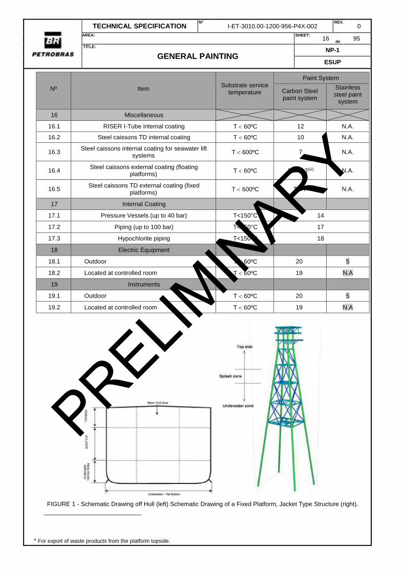
16 Miscellaneous
16.1 RISER I-Tube internal coating T 60ºC 12 N.A.
16.2 Steel caissons TD internal coating T 60ºC 10 N.A.
16.3 Steel caissons internal coating for seawater lift
systems T 600ºC 7 N.A.
16.4 Steel caissons external coating (floating
platforms) T 60ºC 1 and 2(iii) N.A.
16.5 Steel caissons TD external coating (fixed
platforms) T 600ºC TSA N.A.
17 Internal Coating
17.1 Pressure Vessels (up to 40 bar) T<150°C 14
17.2 Piping (up to 100 bar) T<150°C 17
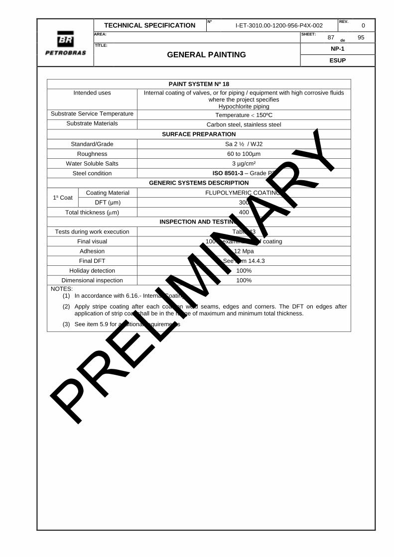
17.3 Hypochlorite piping T<150°C 18
18 Electric Equipment
18.1 Outdoor T 60ºC 20 5
18.2 Located at controlled room T 60ºC 19 N.A
19 Instruments
19.1 Outdoor T 60ºC 20 5
19.2 Located at controlled room T 60ºC 19 N.A
FIGURE 1 - Schematic Drawing off Hull (left) Schematic Drawing of a Fixed Platform, Jacket Type Structure (right).
iii For export of waste products from the platform topside.
PRELIMIN
ARY
TECHNICAL SPECIFICATION Nº
I-ET-3010.00-1200-956-P4X-002 REV.
0
AREA:
SHEET: 17
de 95
TÍTLE:
GENERAL PAINTING NP-1
ESUP
5.3 HDG (HOT DIP GALVANIZING)
5.3.1 This item does not apply to the galvanized coating on semi-finished products such as wire, tube or sheet, galvanized in specialized or automatic plants.
5.3.2 The minimum average coating mass (and equivalent thickness) on any individual test area of the hot dip galvanized articles shall be as follows:
a) Steel 5 mm thick and over: 600 g/m2 (84 μm);
b) Steel under 5 mm thick but not less than 2 mm: 450 g/m2 (63 μm);
c) Steel less than 2 mm: 350 g/m2 (49 μm);
d) Centrifuged work: 300 g/m2 (42 μm);
e) Threaded work: 300 g/m2 (42 μm);
f) Gray and malleable iron casting: 600 g/m2 (84 μm).
5.3.3 Galvanized surfaces shall be externally painted as required in Table 2.
5.3.4 The following standards shall be applied on galvanized products:
a) ASTM A123 for structural and piping components;
b) ASTM A153 for threaded components.
c) ISO 1461.
5.3.5 In no case materials with yield strength greater than 400 MPa shall be galvanized.
5.3.6 HDG coatings shall not be used on Flare´s top platform due the risk of Liquid Metal Embrittlement of stainless steel material in case of flame impingement.
5.3.7 HDG coating shall not be used under insulation or immersed in water at operational temperatures over 60°C.
5.4 COATING UNDER THERMAL INSULATION
5.4.1 Insulated piping system or equipment requires the application of coating in accordance with system 7 as stated in TABLE 3
Table 3 -Requirement of coating.
Material Operating temperature
Carbon steel Cycling or dual process -20ºC<T<320ºC (or lower)note 1 - 5ºC <T< 120ºC
Austenitic ss Cycling or dual process -20ºC<T<320ºC (or lower)note 1 50ºC <T< 175ºC
Duplex ss Cycling or dual process -20ºC<T<320ºC (or lower)note 1 90ºC <T< 175ºC
Super duplex ss Cycling or dual process -20ºC<T<320ºC (or lower)note 1 100ºC <T<175ºC
Note 1: Some Pipes and Equipments cycling between higher temperatures (higher than 320ºC) and ambient temperature are also classified as CATEGORY 1. One example is exhaust piping of diesel
engines.
5.5 COATING OF CRITICAL AREAS
5.5.1 DEFINITION
5.5.1.1 Critical points are flanges, valves, supports, nuts, bolts, areas of electrolyte stagnation and crevices.
PRELIMIN
ARY
TECHNICAL SPECIFICATION Nº
I-ET-3010.00-1200-956-P4X-002 REV.
0
AREA:
SHEET: 18
de 95
TÍTLE:
GENERAL PAINTING NP-1
ESUP
5.5.1.2 The critical points to be coated are located in areas were the microclimate is more aggressive and/or located in areas of difficult access in carbon steel.
5.5.1.3 The project drawings shall specify the areas were the critical points are to be coated with a coating for critical areas.
5.5.2 POLYMERIC COATINGS
5.5.2.1 These Critical Points shall be protected against corrosion through specific polymer coatings to avoid direct exposure to the corrosive environment. The painting shall, necessarily, present the following properties:
a) Effective barrier against the action of corrosive media;
b) Working temperature appropriate to the operating condition;
c) Exhibit dimensional stability without showing cracks in the region of application of this coating;
d) Be compatible with existing paint;
e) Easy removal, not interfering in the processes of assembly and disassembly of structures and equipment.
5.5.2.2 Coatings shall meet the requirements of Table 4.
Table 4 - Laboratory Tests - Polymeric Coatings for Critical Areas
Tests Requirements Standards
to be used Min. Max.
Salt spray resistance, h 6000 - ASTM B117
5.6 FLARE SYSTEM AND HIGH STRUCTURAL COMPONENTS (>70m)
5.6.1 All surfaces to be coated above elevation 70000 shall receive thermal spray coating, without considering temperature of substrate.
5.6.2 In case of surfaces subject to temperatures higher than 500°C due to flare radiation, the flare manufacturer shall specify coating material adequate to the limits of low and high temperature of operation.
5.6.3 CONTRACTOR shall observe the Flare Radiation and Dispersion Analysis report to determine the piping systems and equipments affected by flare radiation. The operational temperature shall consider the impact of flare radiation in adition to the operational temperature for determination of paint system.
5.7 PAINTING OF PIPING
5.7.1 Nut-bearing or washer-bearing surfaces of flanges shall receive coating. The coat thickness shall be limited to avoid out-of-squareness and misalignments in flange bolted assembly specially in critical joints
5.7.2 The surface area below welded and bonded supports shall not receive coating. The recomposition of paint scheme shall be applied after assembly of support.
5.7.3 Spring supports and vibration damping devices shall be metallized with aluminum by thermal spray according to I-ET-3010.00-1200-956-P4X-003.
5.7.4 Dissimilar joints.
PRELIMIN
ARY
TECHNICAL SPECIFICATION Nº
I-ET-3010.00-1200-956-P4X-002 REV.
0
AREA:
SHEET: 19
de 95
TÍTLE:
GENERAL PAINTING NP-1
ESUP
5.7.4.1 Dissimilar joints with operational temperature <40°C at outdoor areas shall receive after assembly and thigness testing test a special coating for critical regions according to item 5.5.
5.7.4.2 This requirement is not applicable to piping systems with process fluid containing conductive fluid or H2S-containing process fluids. Those joints shall receive an electric insulation joint.
5.8 PAINTING OF STRUCTURAL TANKS AND HULL
5.8.1 In the plating of each block, at the ends to be welded to other blocks in the ship, a strip of 200 mm by 300 mm shall be left unpainted in the longitudinal reinforcements (longitudinal deck, sides , bottom, double-bottom ceiling and longitudinal bulkheads).
Figure 2- Block joints
5.8.2 Cargo Tanks: Coat does not cover 100% of surface area. Only ceiling and bottom shall be painted according to the instructions below:
5.8.2.1 UPPER AREA - Main Deck Plating Lower Surface and all steel surfaces including transverse and longitudinal bulkheads and their reinforcements up to 4000 mm counted from tank ceiling (Figure 3).
weld
weld
PRELIMIN
ARY
TECHNICAL SPECIFICATION Nº
I-ET-3010.00-1200-956-P4X-002 REV.
0
AREA:
SHEET: 20
de 95
TÍTLE:
GENERAL PAINTING NP-1
ESUP
Figure 3 – Upper and lower area of tank
5.8.2.2 UPPER AREA (WEB FRAMES) – deck transverse web frames 100% painted including a contour strip of 200mm width around the web bracket (Figure 3 and Figure 5).
5.8.2.3 LOWER AREA - Bottom Plating Upper Surface and all steel surfaces including transverse and longitudinal bulkheads and their reinforcements up to a specific height counted from Bottom (Figure 3 and Figure 4). The project shall specify the height considering Basic Sediments and Water (BSW) expected and the specification of an off-spec tank. The recommend practice is 2000mm.
5.8.2.4 LOWER AREA (WEB FRAMES) – bottom transverse web frames 100% painted including a contour strip of 200 mm width around the web bracket (Figure 5).
5.8.2.5 TRANVERSE BULKHEADS (HORIZONTAL STRINGERS & BRACKETS) – top surface of horizontal stringers and brackets (including internal side of flanges and top surfaces of horizontal brackets attached to longitudinal bulkheads) up to 300 mm above the top surface of stringers & brackets (strip painted on the surface of transverse and longitudinal bulkhead) (Figure 4, Figure 6, Figure 7 and Figure 8 ).
5.8.3 SETTLING TANK: Paint system shall cover 100% of surface area.
5.8.4.1 The paint systems specified at table 2 for structural tanks and hull are classified as Category III for the effect of a coating system on coating breakdown factors, in accordance with DNVGL-RP-B401.
5.8.4.2 The constants do not account for significant damage to paint coatings during fabrication and installation. Continuous damages over 25 m² or over 2% of the total area requires total repaint with Sa 2 ½ surface preparation, or, if not mandatory the first, a change to category II for paint system breakdown factor. All other requirements regarding repair in this specification are applicable.
5.8.5 The hull painting shall observe the requirements of I-ET-3010.00-1000-950-P4X-001- MARINE BIOFOULING
5.8.6 DOUBLE PLATE
5.8.6.1 An anti-abrasion coating shall be applied at double plates of tanks (ballast, cargo and others as specified).
5.8.6.2 The anti-abrasion coating is an epoxy novolac based coating with high resistance to erosion-corrosion. The coatings shall meet the requirements of Table 5
Table 5 - Laboratory Tests - Polymeric Coatings for Critical Areas
Note: An ASTM G32 test at the paint is desired.
Tests Requirements
Standards to be used Min. Max.
Atlas cell @ 60 ° C 2000 - ASTM C868
Autoclave immersion 2000 - NACE TM 0185
Abrasion (1000 cicles) 7 mg ASTM 4060 (CS17)
Note (1): Temperature = 150 °C. Pressure: Water vapor pressure at 150 °C. Solution composition: Chloride concentration = 70.000 ppm; Sodium acetate trihydrate concentration = 21 g/L; Initial pH = 5 (adjustment done with 37% HCl); Composition of the gas phase: 96% CO2; 4.0% H2S Condition stagnant and desaerated.
PRELIMIN
ARY
TECHNICAL SPECIFICATION Nº
I-ET-3010.00-1200-956-P4X-002 REV.
0
AREA:
SHEET: 24
de 95
TÍTLE:
GENERAL PAINTING NP-1
ESUP
5.9 DESIGN AND FABRICATION FOR INTERNAL COATING
5.9.1 Equipment to be lined shall be sufficiently rigid that there is no possibility of deformation, which would result in damage to the lining during transportation, installation and operation. The arrangements for the lifting of the equipment shall be determined at the design stage.
5.9.2 Structural support members should be installed on the exterior of the vessel and/or equipment. However, if such members are installed internally, they shall be fabricated of simple shapes such as smooth round bars or pipe for ease of applying the lining material.
5.9.3 The design of all equipment shall allow for access during the preparation of the surface and application of the lining and for venting of fumes evolved during the operation. In completely enclosed vessels there shall be at least one manhole with a minimum diameter as large as practical for the vessel being lined and additional branch or openings should be provided in order to allow an adequate circulation of air.
5.9.4 Pressure vessel internal fittings which have to be installed after completion of the lining process shall be designed to be lined or fabricated from materials that will not be affected by the process conditions.
5.9.5 All field connections of the spool/equipment shall be flanged. If for any reason screw connections cannot be avoided, these parts shall be fabricated in corrosion resistant materials.
5.9.6 The bore of any internal fitting bolt hole shall be dimensioned for the diameter of the bolt plus the lining system thickness.
5.9.7 The pressure vessels nozzles bore diameter shall be larger enough in order to allow access for painting the nozzle with the lining.
5.9.8 Equipment internal surface, as well as equipment internal accessories (stiffeners, supports, etc.) welded to equipment walls or structure, shall be totally coated. Other accessories shall be analyzed by PETROBRAS, to determine if they shall be coated or not.
5.9.9 Pressure tests as required by the design codes of the lines/equipment shall be performed and approved before applying the coating.
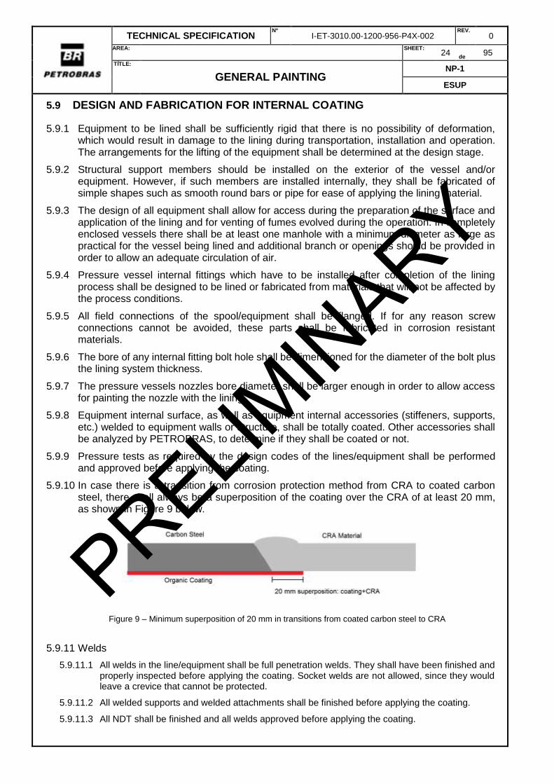
5.9.10 In case there is a transition from corrosion protection method from CRA to coated carbon steel, there shall always be a superposition of the coating over the CRA of at least 20 mm, as shown in Figure 9 below.
Figure 9 – Minimum superposition of 20 mm in transitions from coated carbon steel to CRA
5.9.11 Welds
5.9.11.1 All welds in the line/equipment shall be full penetration welds. They shall have been finished and properly inspected before applying the coating. Socket welds are not allowed, since they would leave a crevice that cannot be protected.
5.9.11.2 All welded supports and welded attachments shall be finished before applying the coating.
5.9.11.3 All NDT shall be finished and all welds approved before applying the coating.
PRELIMIN
ARY
TECHNICAL SPECIFICATION Nº
I-ET-3010.00-1200-956-P4X-002 REV.
0
AREA:
SHEET: 25
de 95
TÍTLE:
GENERAL PAINTING NP-1
ESUP
5.9.11.4 All welds shall be continuous. Visual inspection of 100% of the length of the welds (root and face side) shall be performed, and the following is not acceptable:
Lack of penetration;
Lack of fusion;
Excess penetration;
Root undercut;
Cracks;
Pores;
Any defect that may affect the continuity of the coating.
5.9.11.5 The weld transition with the adjacent base metals shall be smooth (ISO 8501-3 Grade P2). Grinding of the reinforcement may be necessary.
5.9.11.6 Crevices (as in socket welds) and sharp corners are not allowed. All corners shall be ground to a minimum radius equal to or greater than 5 mm.
5.9.12 Branch Connections
5.9.12.1 All branch connections shall be full penetration welds, as in “tees” or in integrally reinforced branch pieces. Branch connections that are connected by anything different from full penetration welds or that may result in any kind of crevice shall not be used.
5.9.12.2 All branch connections shall be short enough so that the visual inspection of the root of the connecting weld can be performed, as well as to facilitate the application of the coating and to perform the inspection that comes after coating.
5.9.12.3 All sharp corners in the branch connections shall be ground to a minimum radius of 5 mm (Figure 10).
Figure 10 – Branch connections shall always be connected with full penetration welds, so that no crevices are formed. Sharp corners shall be ground to 5 mm minimum radius.
5.9.13 Flanges
5.9.13.1 The internal coating shall extend to the flange faces, as shown on the Figures below. This type of coating is only compatible with Flat Face (FF), Raised Face (RF) or Ring Type Joint (RTJ) flanges. Internal organic coating shall not be applied to compact type flanges, or any other type of mechanical connection or coupling.
5.9.13.2 All sharp corners in the flange faces shall be ground to a minimum radius of 5 mm (Figure 11).
5 mm radius grinding for
sharp corners
Full penetration
welds
5 mm radius grinding for
sharp corners
PRELIMIN
ARY
TECHNICAL SPECIFICATION Nº
I-ET-3010.00-1200-956-P4X-002 REV.
0
AREA:
SHEET: 26
de 95
TÍTLE:
GENERAL PAINTING NP-1
ESUP
Figure 11 – Flange sharp corners shall be ground to 5 mm minimum radius.
5.9.13.3 Flat Face (FF) flanges shall be coated through all contact surface (Figure 12). Raised Face (RF) flanges shall be coated through all raised portion (Figure 13).
Figure 12 – Coating (light blue) in FF flange
Figure 13 – Coating (light blue) in RF flange
5.9.13.4 RTJ flanges shall be covered through the entire raised portion until the groove. The groove shall be coated with Inconel 625 (Figure 14). The superposition of the CRA overlay with the coating region shall extend to a minimum of 10 mm (in flanges only; other areas of piping/equipment shall extend to 20 mm as in Figure 9).
PRELIMIN
ARY
TECHNICAL SPECIFICATION Nº
I-ET-3010.00-1200-956-P4X-002 REV.
0
AREA:
SHEET: 27
de 95
TÍTLE:
GENERAL PAINTING NP-1
ESUP
Figure 14 – Coating in RTJ flange. The ring grooves shall be coated in CRA
5.9.13.5 After applying the coating all flange faces shall be protected with a plastic or wood cover.
5.10 COLOR OF PAINT SYSTEMS
5.10.1 Color specification for paint systems, required identification of equipment, pipelines, structures, etc., or for safety reasons, is according to DR-ENGP-I-1.15- COLOR CODING
5.10.2 Bright and light colors shall be selected for internal coatings of tanks and confined spaces in order to facilitate the visual identification of corrosion spots during inspections.
5.10.3 If the requirement for painting is only due to color, the paint system n° 5 may be applied.
5.10.3.1 For polymeric composites only a finishing coat is necessary.
6 COATINGS MATERIAL
6.1 SURFACE TOLERANT EPOXY PAINT
6.1.1 This paint shall be able to be applied on dry or wet surfaces under severe conditions of humidity (up to 100% relative humidity).
6.1.2 The requirements for the ready-to-apply product, with components A and B duly mixed, are set out in table 6. The tests shall be done at 25 °C.
Table 6 - Characteristics of the ready-to-apply surface tolerant epoxy paint (components A and B duly mixed).
TESTS DFT (m) REQUIREMENTS
STANDARD Min. Max.
Pot-Life of Mixture (h) - 3 - ABNT NBR 15742
Flash-Point (°C) - 55 - ASTM D56
Sagging (μm) - 150 - ASTM D4400
Drying time to tack free (h) 100 a 150 - 6 ASTM D1640
Drying time to repaint (h) 100 a 150 12 120 ASTM D1640
6.1.3 The dry film characteristics are established in TABLE 7
Table 7 – Dry film surface tolerant epoxy paint characteristics
TESTS DFT (m) REQUIREMENTS
STANDARD Min. Max.
Cyclic Corrosion Test - Type I, Cycle (168 h) 425 - 475 25 - 6.1.3.1 and 6.1.3.2
Cyclic Corrosion Test - Type III, Cycle (168 h) 425 - 475 20 - 6.1.3.3 and 6.1.3.4
Gloss - 60°, UB 425 - 475 70 - ASTM D523 Note: (1) failure type A/B is not acceptable (2) Method D – Equipment type IV or Method E – Equipment Type V (hydraulic automatic)
6.1.3.1 The cyclic corrosion test I, 25 cycles (168 h each, totaling 4200 h) shall be performed exposing the test panels to the following conditions:
a) Exposure to neutral saline mist for 72 h according to ISO 9227 but using artificial sea water in accordance with ASTM D1141;
PRELIMIN
ARY
TECHNICAL SPECIFICATION Nº
I-ET-3010.00-1200-956-P4X-002 REV.
0
AREA:
SHEET: 28
de 95
TÍTLE:
GENERAL PAINTING NP-1
ESUP
b) Exposure to UV-A and condensation of moisture for 80 hours, according to ASTM G154; the cycle shall be performed as follows: exposure to UV-A at 60 ° C for 4 h and exposure to condensation at 50 ° C for 4 h;
c) Dry at room temperature for 16 h.
6.1.3.2 When observing the panels, blisters or corrosion points shall not be found on the surface, neither shall penetration in the notch exceeding 8 mm be observed after 25 cycles (4200 h) of cyclic corrosion test type I. The maximum chalk allowable shall be correspondent to chalk rate No. 4 of ASTM D 4214.
6.1.3.3 In the cyclic corrosion test type III, based on adaptations of ISO 12944-9, shall be performed 20 cycles, 168 h each one, totalizing 3360 h, exposing the test panels to the followings conditions:
a) Exposure to neutral salt spray for 72 hours, according to ISO 9227 standard, using 5% sodium chloride;
b) Exposure to low temperature (-10 ° C) for 24 h;
c) Exposure to UV-A and condensation for 72 hours, according to ASTM G154; the cycle to be performed is as follows: Exposure to UV-A at 60 ° C for 4 h and exposure to condensation at 50 ° C for 4 h;
6.1.3.4 When observing the panels, blisters or corrosion points shall not be found on the surface, neither shall penetration in the notch exceeding 10 mm be observed after 20 cycles (3 360 h) of cyclic corrosion test type III. The maximum chalk allowable shall be correspondent to chalk rate No. 4 of ASTM D 4214
6.1.3.5 A horizontal scribe with 50 mm of length and 2 mm of width, parallel with the smaller edge and 70 mm from the bottom, shall be made in each test panel under the cyclic corrosion tests. The scribe shall be made using a milling cutter and the coating shall be removed exposing the metallic substrate.
6.1.3.6 The coating scribe make possible data evaluating such as: corrosion expansion, blistering and cracking caused by the perforation on the coating. Furthermore, provide means of evaluating the anti-corrosive ability of the coating system under test.
6.1.3.7 In order to measure the corrosion under creep expansion, measuring of corrosion under creep corresponding to the peeling of coating took place under creep. Nine measurements shall be performed along the creep length, one measurement at the center and 8 measurements equidistant 5 mm from the center. The equation below shall be used to evaluate the average corrosion under creep:
A = (P – L) / 2
Where:
A = average corrosion under creep (mm);
P = average of the 9 measurements (mm);
L = width of the scribe (2 mm)
NOTE: In order to use the paint system for Potable Water Tanks, it shall be certified in accordance with NSF 61: Drinking Water System Components - Health Effects.
PRELIMIN
ARY
TECHNICAL SPECIFICATION Nº
I-ET-3010.00-1200-956-P4X-002 REV.
0
AREA:
SHEET: 29
de 95
TÍTLE:
GENERAL PAINTING NP-1
ESUP
6.2 HIGH TICKNESS EPOXY PAINT (LOW VOC).
6.2.1 The requirements for the ready-to-apply product, with components A and B duly mixed, are set out in TABLE 8.The tests shall be done at 25 °C.
Table 8 - Characteristics of the ready-to-apply high thickness epoxy paint (components A and B duly mixed).
TESTS DFT (m) REQUIREMENTS
STANDARD Min. Max.
Solids by volume 80 ASTM D 2697
Pot-Life of Mixture (h) - 2 - ABNT NBR 15742
Coverage Table 8 ABNT NBR 9676
Sagging (μm) - 240 - ASTM D4400
Drying time to tack free (h) 200 - 250 - 4 ASTM D1640
6.2.2 Note: For painting in aluminum color, consider the following values:
a) Specific mass (g / cm³) = 1,0 minimum and 1,4 maximum;
b) Solids by mass: 80% minimum;
c) Solids by volume: 70% minimum.
Table 9 – Colors and coverage power (Pfund plate criptometer n° 7)
Color PB
CODE Munsell Requirement
Safety orange 1867 2,5 YR 6/14 20
Petrobras Yellow 2386 2,5 Y 8/12 20
Safety yellow 2586 5 Y 8/12 20
Safety red 1547 5 R 4/14 20
white 0095 N 9.5 15
Light grey 0065 N 6.5 15
Ice grey 0080 N 8 15
Piping cream 2273 10 YR 7/6 15
Pastel green 3582 5 G 8/4 15
Petrobras green 3355 2,5 G 5/10 15
Safety green 3263 10 GY 6/6 15
Petrobras blue 5134 7,5 PB 3/8 10
Safety blue 4845 2.5 PB 4/10 10
Dark grey 0035 N 3.5 10
Iron oxide red 1733 10 R 3/6 10
black 0010 N 1 10 Note: For other colors, consider: a) light yellow or red: 20 b) grey or green colors: 15 c) blue colors: 10
6.2.3 The dry film characteristics are established in TABLE 10
Table 10 – Dry film surface tolerant epoxy paint characteristics
TESTS DFT (m) REQUIREMENTS
STANDARD Min. Max.
Resistance to salt spray 400 - 450 2 000 ASTM B 117
Resistance to 100% relative humidity 400 - 450 2 000 ASTM D 2247
Resistance to immersion in distilled water at 40°C 400 - 450 2 000 ASTM D 870
Resistance to immersion in salt water 3.5% NaCl (40°C) 400 - 450 2 000 ASTM D 1308
Resistance to immersion in NaOH at 10% 400 - 450 2 000 ASTM D 1308
Gloss - 60°, UB 200 - 240 60 - ASTM D523 Note: (1) failure type A/B is not acceptable (2) Method D – Equipment type IV or Method E – Equipment Type V (hydraulic automatic)
Resistance to immersion in 40% H2SO4, at 10% 350 -400 1500 - ASTM D 1308 Note: (1) failure type A/B is not acceptable (2) Method D – Equipment type IV or Method E – Equipment Type V (hydraulic automatic)
6.3.3 In order to use the paint system for Potable Water Tanks, it shall be certified in accordance with NSF 61.
6.4 EPOXY NOVOLAC LOW VOC
6.4.1 The requirements for the ready-to-apply product, with components A and B duly mixed, are set out in table 13. The tests shall be done at 25 °C.
Table 13 - Characteristics of the ready-to-apply epoxy novolac low voc (components A and B duly mixed).
TESTS DFT (m) REQUIREMENTS
STANDARD Min. Max.
Solids by volume - 75 - ISO 3233
Sagging (μm) - 250 - ASTM D4400
Drying time to touch (h) - - 12 ASTM D1640
Total cure time - - 24 ASTM D1640
6.4.2 The dry film characteristics are established in TABLE 14
PRELIMIN
ARY
TECHNICAL SPECIFICATION Nº
I-ET-3010.00-1200-956-P4X-002 REV.
0
AREA:
SHEET: 31
de 95
TÍTLE:
GENERAL PAINTING NP-1
ESUP
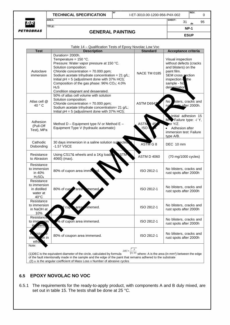
Table 14 – Qualification Tests of Epoxy Novolac Low Voc
Test Description Standard Acceptance criteria
Autoclave immersion
Duration= 2000h. Temperature = 150 °C. Pressure: Water vapor pressure at 150 °C. Solution composition: Chloride concentration = 70.000 ppm; Sodium acetate trihydrate concentration = 21 g/L; Initial pH = 5 (adjustment done with 37% HCl); Composition of the gas phase: 96% CO2; 4.0% H2S Condition stagnant and desaerated.
NACE TM 0185
Visual inspection without defects (cracks and blisters) on the paint film. SEM cross section inspection of the sample - No delamination.
Atlas cell @ 40 ° C
50% of atlas cell volume with solution Solution composition: Chloride concentration = 70.000 ppm; Sodium acetate trihydrate concentration= 21 g/L; Initial pH = 5 (adjustment done with 37% HCl);
ASTM D6943 No blisters, cracks and rust spots after 2000h.
Adhesion (Pull-Off
Test), MPa
Method D – Equipment type IV or Method E – Equipment Type V (hydraulic automatic)
ASTM D 4541 ISO 4624
Initial adhesion 15 MPa Failure type: -/ Y, Y or Y/Z.
Adhesion after immersion test: Failure type A/B.
Cathodic Disbonding
30 days immersion in a saline solution subjected to -1.57 VSCE
ASTM G 8 DEC 10 mm
Resistance to Abrasion
Using CS17& wheels and a 1Kg loading (ASTM D-4060) (max).
ASTM D 4060 (70 mg/1000 cycles)
Resistance to immersion
in 40% H2SO4
80% of cupon area immersed. ISO 2812-1 No blisters, cracks and rust spots after 2000h
Resistance to immersion
in distilled water at
40°C
80% of cupon area immersed. ISO 2812-1 No blisters, cracks and rust spots after 2000h
Resistance to immersion in NaOH at
10%
80% of cupon area immersed. ISO 2812-1 No blisters, cracks and rust spots after 2000h
Resistance to immersion
in xylene 80% of cupon area immersed. ISO 2812-1
No blisters, cracks and rust spots after 2000h
Resistance
immersion in ethanol
80% of coupon area immersed. ISO 2812-1 No blisters, cracks and rust spots after 2000h
Note:
(1)DEC is the equivalent diameter of the circle, calculated by formula where: A is the area (in mm²) between the edge of the fault intentionally made in the sample and the edge of the paint that remains adhered to the substrate
.(2) is the angular coefficient of Mass Loss x Number of abrasive cycles
6.5 EPOXY NOVOLAC NO VOC
6.5.1 The requirements for the ready-to-apply product, with components A and B duly mixed, are set out in table 15. The tests shall be done at 25 °C.
PRELIMIN
ARY
TECHNICAL SPECIFICATION Nº
I-ET-3010.00-1200-956-P4X-002 REV.
0
AREA:
SHEET: 32
de 95
TÍTLE:
GENERAL PAINTING NP-1
ESUP
Table 15 - Characteristics of the ready-to-apply epoxy novolac no voc (components A and B duly mixed).
TESTS DFT (m) REQUIREMENTS
STANDARD Min. Max.
Solids by volume - 95 - ISO 3233
Flash point (A) 100 ASTM D56
Flash point (B) 66 ASTM D56
Sagging (μm) - 300 - ASTM D4400
Drying time to touch (h) - - 12 ASTM D1640
Total cure time - - 24 ASTM D1640
6.5.2 The dry film characteristics are established in TABLE 16
Table 16 – Qualification Tests of Epoxy Novolac no Voc
Test Description Standard Aceptance criteria
Atlas cell @ 40 ° C
50% of atlas cell volume with solution Solution composition: Chloride concentration = 70.000 ppm; Sodium acetate trihydrate concentration= 21 g/L; Initial pH = 5 (adjustment done with 37% HCl);
ASTM D6943 No blisters, cracks ans rust spos after 2000h..
Adhesion (Pull-Off
Test), MPa
Method D – Equipment type IV or Method E – Equipment Type V (hydraulic automatic)
ASTM D 4541 ISO 4624
Initial adhesion 15 MPa Failure type: -/ Y, Y ou Y/Z.
Adhesion after immersion test: Failure type A/B.
Cathodic Disbonding
30 days immersion in a saline solution subjected to -1.57 VSCE
ASTM G 8 DEC 10 mm
Resistance to Abrasion
Using CS17& wheels and a 1KG loading (ASTM D-4060) (max).
ASTM D 4060 (70 mg/1000 cicles)
Resistance to immersion
in 40% H2SO4
80% of cupon area immersed. ISO 2812-1 No blisters, cracks and rust spots after 2000h
Resistance to immersion
in distilled water at
40°C
80% of cupon area immersed. ISO 2812-1 No blisters, cracks and rust spots after 2000h
Resistance to immersion in NaOH at
10%
80% of cupon area immersed. ISO 2812-1 No blisters, cracks and rust spots after 2000h
Resistance to immersion
in xylene 80% of cupon area immersed. ISO 2812-1
No blisters, cracks and rust spots after 2000h
Resistance immersion in
ethanol 80% of cupon area immersed. ISO 2812-1
No blisters, cracks and rust spots after 2000h
Note:
(1)DEC is the equivalent diameter of the circle, calculated by formula , where: A is the area (in mm²) between the edge of the fault intentionally made in the sample and the edge of the paint that remains adhered to the substrate
.(2) is the angular coefficient of Mass Loss x Number of abrasive cycles
PRELIMIN
ARY
TECHNICAL SPECIFICATION Nº
I-ET-3010.00-1200-956-P4X-002 REV.
0
AREA:
SHEET: 33
de 95
TÍTLE:
GENERAL PAINTING NP-1
ESUP
6.6 EPOXY NOVOLAC WITHOUT SOLVENTS ENHANCED WITH GLASS FLAKES OR CERAMIC PIGMENTS
6.6.1 This paint is solvent free, cured at room temperature, pigmented with glass flakes or ceramic pigments.
6.6.2 As an internal coating, it may be used for maximum pressure of 100 bar and maximum operational temperature of 150 ° C.
6.6.3 The requirements for the ready-to-apply product, with components A and B duly mixed, are set out in table 17 the tests shall be done at 25 °C.
Table 17 - Characteristics of the ready-to-apply epoxy Novolac with glass flakes or ceramic pigments (components A
and B duly mixed).
TESTS DFT (m) REQUIREMENTS
STANDARD Min. Max.
Solids by volume - 95 - ISO 3233
Flash point (A) 100 - ASTM D56
Flash point (B) 66 ASTM D56
Sagging (μm) - 400 - ASTM D4400
Drying time to touch (h) - - 12 ASTM D1640
Total cure time - - 24 ASTM D1640
6.6.4 The dry film characteristics are established in TABLE 18
PRELIMIN
ARY
TECHNICAL SPECIFICATION Nº
I-ET-3010.00-1200-956-P4X-002 REV.
0
AREA:
SHEET: 34
de 95
TÍTLE:
GENERAL PAINTING NP-1
ESUP
Table 18 – Qualification Tests of Epoxy Novolac with glass flakes or ceramic pigments Test Description Standard Acceptance criteria
Autoclave immersion
Duration= 2000h. Temperature = 150 °C. Pressure: Water vapor pressure at 150 °C. Solution composition: Chloride concentration = 70.000 ppm; Sodium acetate trihydrate concentration = 21 g/L; Initial pH = 5 (adjustment done with 37% HCl); Composition of the gas phase: 96% CO2; 4.0% H2S Condition stagnant and desaerated.
NACE TM 0185
Visual inspection without defects (cracks and blisters) on the paint film. SEM cross section inspection of the sample - No delamination.
Atlas cell @ 80 ° C
50% of atlas cell volume with solution Solution composition: Chloride concentration = 70.000 ppm; Sodium acetate trihydrate concentration= 21 g/L; Initial pH = 5 (adjustment done with 37% HCl);
ASTM D6943 No blisters, cracks and rust spots after 2000h.
Adhesion (Pull-Off
Test), MPa
Method D – Equipment type IV or Method E – Equipment Type V (hydraulic automatic)
ASTM D 4541 ISO 4624
Initial adhesion 15 MPa Failure type: -/ Y, Y or Y/Z.
Adhesion after immersion test: Failure type A/B.
Cathodic Disbonding
30 days immersion in a saline solution subjected to -1.57 VSCE
ASTM G 8 DEC 10 mm
Resistance to Abrasion
Using CS17& wheels and a 1KG loading ASTM D 4060 (70 mg/1000 cycles)
Resistance to immersion
in 40% H2SO4
80% of coupon area immersed. ISO 2812-1 No blisters, cracks and rust spots after 2000h
Resistance to immersion
in distilled water at
40°C
80% of coupon area immersed. ISO 2812-1 No blisters, cracks and rust spots after 2000h
Resistance to immersion in NaOH at
10%
80% of coupon area immersed. ISO 2812-1 No blisters, cracks and rust spots after 2000h
Resistance to immersion
in xylene 80% of coupon area immersed. ISO 2812-1
No blisters, cracks and rust spots after 2000h
Resistance immersion in
ethanol 80% of coupon area immersed. ISO 2812-1
No blisters, cracks and rust spots after 2000h
Note: (1)DEC is the equivalent diameter of the circle, calculated by formula Erro! Indicador não definido., where: A is the area (in mm²) between the edge of the fault intentionally made in the sample and the edge of the paint that remains adhered to the substrate
.(2) is the angular coefficient of Mass Loss x Number of abrasive cycles
Adhesion (Pull-Off Test), MPa 120-140 10² - ASTM D 4541³
Note: (1) In this test, a 4-hour cycle under UV-A radiation and 4 hours under moisture condensation shall be used.
After exposure time, no film scaling shall be observed. The brightness shall be measured before and after the test. A difference of more than 10% of these values is not allowed
(2) Failure type A/B the value shall be superior to 15Mpa. For other types of failure, the result shall be superior to 10Mpa.
(3) Method D – Equipment type IV or Method E – Equipment Type V (hydraulic automatic)
6.8 ZINC RICH SHOP PRIMER
6.8.1 The requirements for the ready-to-apply product, with components A and B duly mixed, are set out in table 21 the tests shall be done at 25 °C.
Table 21 - Characteristics of the ready-to-apply zinc rich shop primer (components A and B duly mixed).
TESTS REQUIREMENTS
STANDARD Min. Max.
Solids by volume 25 ISO 3233
Pot-Life of Mixture (h) 18 - ISO 9514
Thickness per coat 15 25
Drying time to tack free (h) - 6 ASTM D1640
Total curing time 72 ASTM D1640
6.8.2 For ballast tanks, if the zinc-rich shop primer does not meet IMO MSC.215 (82), it shall be removed at least 70% of the painted area.
6.9.1 Sealant paint is applied to ensure compatibility between the anti-corrosion system and the anti-fouling system.
6.10 ANTI-FOULING PAINT
6.10.1 This is a tin-free antifouling paint whose efficiency is guaranteed up to 5 years of immersion under static conditions.
6.10.2 The antifouling coatings system for offshore production units shall have antifouling technology for static condition with proved efficiency.
6.10.3 The following technologies are recognized as acceptable:
a) Fouling release
b) Fouling defense
c) Silyl acrylate static
6.10.4 Other antifouling technologies shall be submitted for PETROBRAS approval.
6.10.5 The minimum thickness of the film is 100 μm per coat by means of airless spray gun.
6.10.6 The paint manufacturer shall provide assurance on the performance of the anti-fouling system.
6.11 HIGH ABRASION EPOXY PAINT
6.11.1 Epoxy cured epoxy paint with high resistance to abrasion and impact. This paint shall be capable of being applied with a minimum film thickness of 300 μm per layer.
6.11.2 The dry film characteristics shall be as follows:
a) Barcol Hardness: 40 (min);
b) 60 ° brightness: 60 (min);
c) Resistance to abrasion: ≤ 70 mg / 1000 cycles, according to ASTM D 4060. This test evaluates the relationship between the loss of coating mass and the number of abrasive cycles. The abrasion resistance test shall be performed using a CS-17 abrasive disc with a 1 kg load.
6.12 NON-SKID EPOXI PAINT
6.12.1 Epoxy-based paint with a minimum dry film thickness of 3.0 mm, high abrasion resistance and high chemical resistance.
6.12.2 The non-slip property shall be obtained by dispersion of quartz crystals or other materials having a particle size between 2mm (sieve 10) and 4 mm (sieve 5), directly into the paint. The product must be supplied with the previously incorporated aggregates not being allowed quartz sprinkling after the application.
6.12.3 The requirements for the ready-to-apply product, with components A and B duly mixed, are set out in table 22. The tests shall be done at 25 °C.
PRELIMIN
ARY
TECHNICAL SPECIFICATION Nº
I-ET-3010.00-1200-956-P4X-002 REV.
0
AREA:
SHEET: 37
de 95
TÍTLE:
GENERAL PAINTING NP-1
ESUP
Table 22 - Characteristics of the ready-to-apply non-skid epoxy paint (components A and B duly mixed).
TESTS DFT (m) REQUIREMENTS
STANDARD Min. Max.
Solids by volume 70 ISO 3233-1
Drying time to touch (h) 180 a 220 - 12 ASTM D1640
Drying time to repaint (h) 180 a 220 24 72 ASTM D1640
6.12.4 The dry film characteristics are established in TABLE 23
Table 23 – Dry film non-skid epoxy characteristics
TESTS DFT (m) REQUIREMENTS
STANDARD Min. Max.
Resistance to salt spray 4000 ASTM B 117
Resistance to immersion in NaOH @ 30% (25°C) 1000 ASTM D1308
Resistance to xylene, h - 2 000 ASTM D1308
Resistance to impact, J 2mm ISO 6272-1
6.13 SPLASH ZONE PAINT
6.13.1 The requirements for the ready-to-apply product, with components A and B duly mixed, are set out in table 24.The tests shall be done at 25 °C.
Table 24 - Characteristics of the ready-to-apply splash zone paint (components A and B duly mixed).
TESTS REQUIREMENTS
STANDARD Min. Max.
Solids by volume 95 ISO 3233
Flash point Comp A (°C) 100 - ASTM D56
Flash point Comp B (°C) 66 ASTM D56
Sagging (μm) 500 - ASTM D4400
Drying time to touch (h) - 12 ASTM D1640
Drying time to repaint (h) - 24 ASTM D1640
6.13.2 The dry film characteristics are established in TABLE 25.
Table 25 – Dry film splash zone characteristics
TESTS DFT (m) REQUIREMENTS
STANDARD Min. Max.
Cyclic Corrosion Test - Type I, Cycle (168 h) 500 25 - 6.1.3.1 and 6.1.3.2
Cyclic Corrosion Test - Type III, Cycle (168 h) 500 20 - 6.1.3.3 and 6.1.3.4
Cathodic Disbonding (30 days) 500 - 10 ASTM G8
Resistance to Abrasion 100 mg / 1000 cycles ASTM D 4060³
Resistance to distilled water(40°C) 500 2 000 ASTM D 1308
Adhesion (Pull-Off Test), MPa 500 151 - ASTM D 45412
Impact resistance (20°C) 500 4J ISO 21809-2 Note: (1) failure type A/B is not acceptable (2) Method D – Equipment type IV or Method E – Equipment Type V (hydraulic automatic) (3) Using CS17 wheels and a 1KG loading
6.14 EPOXY ADHERENCE PAINT
6.14.1 It is used to give adhesion to stainless steel alloy, galvanized steels and substrates of non-ferrous alloys. It shall follow the recommendations of the paint manufacturer.
PRELIMIN
ARY
TECHNICAL SPECIFICATION Nº
I-ET-3010.00-1200-956-P4X-002 REV.
0
AREA:
SHEET: 38
de 95
TÍTLE:
GENERAL PAINTING NP-1
ESUP
6.15 CORROSION UNDER INSULATION (CUI) COATINGS
6.15.1 The paint shall meet the test requirements described in Table 26.
Table 26 - CUI Coatings - Dry Film Characteristics
Properties/Tests Dry film
thickness (Min.) (µm)
Requirements Standards to be
used
Application on Hot Surfaces (°C) 300
(2 x 150) 150°C (min.)
Salt Spray Resistance (2,000 h) Specimens cured for 3 days @
25°C.
300 (2 x 150)
Corrosion from the incision = 2.0 mm (max.)
ASTM B117 ASTM D610
(See Note 1)
Degree of rusting = 10/9
No blistering, cracking or peeling.
Salt Spray Resistance (2,000 h) Specimens exposed @ 205°C for
96 h before testing
300 (2 x 150)
Corrosion from the incision = 2.0 mm (max.)
ASTM B117 ASTM D610
(See Note 1)
Degree of rusting = 10/9
No blistering, cracking or peeling.
Cycle of Corrosion Under Insulation (16 cycles)
5 days alternating 8 hours of immersion in distilled water @ 95°C and 16 hours @ 205°C, followed by
2 days @ 205°C
300 (2 x 150)
No blistering, cracking or peeling.
Cyclic Heating 205°C - 8 h
260°C - 16 h 315°C - 8 h
370°C - 16 h 425°C - 8 h
24 hours exposure to salt spray (ASTM B117)
300 (2 x 150)
No corrosive attack, blistering, cracking or peeling.
ASTM D2485
(See Note 2)
Adhesion (Pull-Off Test) (MPa) (See Note 3)
300 2 MPa ASTM D4541
NOTE 1 For salt spray resistance tests, on the specimens coated with the test product, the incision shall be vertical and parallel to its largest dimension. NOTE 2 In the Cyclic Heating test, the specimens shall be inspected visually after each temperature level for evaluation of any evidence of failure. For this evaluation, the test samples shall be removed from the furnace/muffle and immediately cooled in cold water at (10.0±2.0) °C. After the last temperature level, the specimens shall be exposed in a salt spray chamber (ASTM B117) for 24 hours, after which they are inspected again for final evaluation. NOTE 3 The pull-off test shall be performed in accordance with ASTM D4541 or ISO 4624 using Pneumatic Equipment Type IV (Test Method D) or Automatic Hydraulic Equipment Type V (Test Method E). The types of acceptable failures are: a) ≤ 10 MPa - without failure A/B; b) Failures -/Y, Y or Y/Z > 10 MPa; c) > 12 MPa - for any type of failure. NOTE 4 When not specified in the referenced test standard, specimens shall be made of AISI-1020 carbon steel plate in dimensions of 150 mm x 100 mm x 4 mm. The surface preparation shall be done by abrasive blasting, according to grade Sa 2 ½
of ISO 8501-1 (very thorough blast-cleaning). The roughness profile shall be 50 m to 70 m, of the angular type.
PRELIMIN
ARY
TECHNICAL SPECIFICATION Nº
I-ET-3010.00-1200-956-P4X-002 REV.
0
AREA:
SHEET: 39
de 95
TÍTLE:
GENERAL PAINTING NP-1
ESUP
6.16 INTERNAL COATING
6.16.1 The coating materials shall be pre-qualified in accordance with the requirements stated at in certified laboratories which have a quality system in compliance with ISO 17025 or equivalent. The laboratories shall be accredited by the international Accreditation Forum (IAF) or INMETRO.
6.16.2 Qualification of coating by laboratory methods is required prior to production. Once qualification is made, no further qualification tests are required unless the coating materials or laboratory application methods change. For each qualified material, the supplier shall provide a qualitative analysis. An acceptable method is an infra-red spectrum.
Note: Coatings materials previously qualified by PETROBRAS with same criteria may be accepted.
6.16.3 For the family of organic coating (piping spec 11 and 14) is acceptable fusion bonded epoxy (Table 27 and 28), epoxy novolac paint (Table 28 and 29 ) and fluropolymeric (Table 30) coating materials.
6.16.4 For internally coated piping systems, the internal coating shall be fusion bonded epoxy. Epoxy novolac paint is acceptable for field repair and/or field paint application on spools.
6.16.5 For internally coated equipment, the internal coating shall be epoxy novolac paint or FBE.
6.16.6 Flupolymeric coating material is to be applied only for valves, or for piping / equipment with high corrosive fluids where the project specifies this coating.
Table 27 – Requirements for FBE (ready to apply)
Tests Requirements Standards
Particle size 0,1% max retained on 60 mesh CAN/CSA Z245.20:2010 Subsec. 12.5
Cure cycle Capable of cure at temperature below 260°C -
Tg2 Min.95°C CAN/CSA Z245.20:2010 Subsec. 12.7
Humidity 0,6%wt CAN/CSA Z245.20:2010 Subsec. 12.4
Table 28 – Requirements for epoxy novolac paint and FBE (dry film characteristics)
Resistance to 100 % relative humidity, h 400-800 12 ASTM D2247
Resistance to distilled water @ 40 °C, h 400-800 2000 ISO 2812-1
Resistance to NaOH 30%, h 400-800 2000 ISO 2812-1
Resistance to H2SO4 40%, h 400-800 2000 ISO 2812-1
Resistance to xylene, h 400-800 2000 ISO 2812-1
Elongation (%) 400-800 7 ASTM D522
Impact 400-800 1,7J ASTM D 2794
NOTE (1): The solution to be used shall have the following composition: 70 000 ppm of chloride ions, 21, 0 g/L of sodium acetate trihydrate, initial pH of 5, 0, adjusted with hydrochloric acid. NOTE (2) The gas phase shall be comprised of 96 % of CO2 and 4 % of H2S and, during the test, its pressure shall be kept sufficiently above the water vapor pressure at 150ºC to prevent the solution from boiling. NOTE (3) The abrasion resistance test shall be performed using a CS-17 abrasive wheel with a load of 1 kg. NOTE (4) ABNT NBR 15877:2010, Annex A.2 or ASTM D4541:2009, Method D - Equipment Typo IV NOTE (5) For FBE the dry film thickness (µm) shall be 200-400
PRELIMIN
ARY
TECHNICAL SPECIFICATION Nº
I-ET-3010.00-1200-956-P4X-002 REV.
0
AREA:
SHEET: 40
de 95
TÍTLE:
GENERAL PAINTING NP-1
ESUP
Table 29 – Requirements for epoxy novolac paint (ready to apply)
Tests Requirements
Standards Min. Max.
Solids by volume, % 95 ISO 3233-1
Sagging, μm 400 ASTM D4400
Flash point, ºC comp. A 100 ISO 3679
Flash point, ºC comp. B 66 ISO 3679
Tack-free time, h 12 ASTM D1640
Overcoating time, h 24 ASTM D1640
Table 30 – Requirements for fluropolymeric coating
Tests Requirements¹ Standards
Melt flow rate (2,16 kg / 275ºC) (2) 0,7-1,3 ASTM D 1238
Gas Blistering No blistering at coating film API RP 5L2
Hydraulic blistering No blistering at coating film API RP 5L2
NOTE (1): Test to be performed on dry coat, the DFT shall be 300µm. (2) test coupon type IV, with 50mm/min (3) Immersion in H2S medium: -Duration: 2.000 horas; -Temperature: 120ºC; -Pressure: vapor pressure at test temperature; -Medium composition: - Chloride concentration = 70.000 ppm - Sodium acetate concentration = 21 g / L - pH initial = 5 (adjust with de HCL 37%) - H2S concentration= 4%
PRELIMIN
ARY
TECHNICAL SPECIFICATION Nº
I-ET-3010.00-1200-956-P4X-002 REV.
0
AREA:
SHEET: 41
de 95
TÍTLE:
GENERAL PAINTING NP-1
ESUP
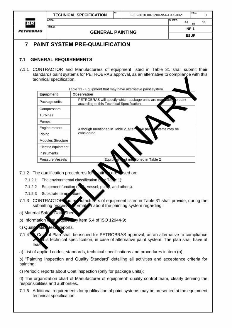
7 PAINT SYSTEM PRE-QUALIFICATION
7.1 GENERAL REQUIREMENTS
7.1.1 CONTRACTOR and Manufacturers of equipment listed in Table 31 shall submit their standards paint systems for PETROBRAS approval, as an alternative to compliance with this technical specification.
Table 31 - Equipment that may have alternative paint system.
Equipment Observation
Package units PETROBRAS will specify which package units are mandatory to paint according to this Technical Specification.
Compressors
Although mentioned in Table 2, alternative paint systems may be considered.
Turbines
Pumps
Engine motors
Piping
Modules Structure
Electric equipment
Instruments
Pressure Vessels Equipment not mentioned in Table 2
7.1.2 The qualification procedures for coatings are based on:
7.1.2.1 The environmental classification (see Table 1);
7.1.2.2 Equipment function (tank, vessel, pump, and others).
7.1.2.3 Substrate temperature.
7.1.3 CONTRACTOR and manufacturers of equipment listed in Table 31 shall provide, during the submitting process, information about the painting system regarding:
a) Material Safety Data Sheet;
b) Information data required by item 5.4 of ISO 12944-9;
c) Qualification tests reports.
7.1.4 A Control Plan shall be issued for PETROBRAS approval, as an alternative to compliance with this technical specification, in case of alternative paint system. The plan shall have at least:
a) List of applied codes, standards, technical specifications and procedures in item (b);
b) “Painting Inspection and Quality Standard” detailing all activities and acceptance criteria for painting;
c) Periodic reports about Coat inspection (only for package units);
d) The organization chart of Manufacturer of equipment´ quality control team, clearly defining the responsibilities and authorities.
7.1.5 Additional requirements for qualification of paint systems may be presented at the equipment technical specification.
PRELIMIN
ARY
TECHNICAL SPECIFICATION Nº
I-ET-3010.00-1200-956-P4X-002 REV.
0
AREA:
SHEET: 42
de 95
TÍTLE:
GENERAL PAINTING NP-1
ESUP
7.1.6 The paint systems shall be pre-qualified in accordance with established performance criteria by test laboratories certified in accordance with ISO/IEC 17025. Laboratories shall be accredited under the IAF or INMETRO.
7.2 REQUIREMENTS FOR QUALIFICATION OF ALTERNATIVE PAINT SYSTEM 2 COATINGS
7.2.1 The coating system shall meet the requirements of ISO 12944-9 for conditions CX and Im2/Im4 and meet the additional tests described in TABLE 32 and TABLE 33.
7.2.2 This coating system is applicable to carbon steel with maximum operating temperature < 120 °C. Examples are: structural steel, exteriors of equipment, vessels, piping and valves (not insulated).
7.2.3 If this coating system is subjected to UV, an additional coat is required. The additional coat shall meet the test requirements described in TABLE 34.
7.2.4 This coating system may be applied in other substrates provided there is a previous PETROBRAS approval.
TABLE 32 - ALTERNATIVE PAINT SYSTEM 2 COATINGS - DRY FILM CHARACTERISTICS
Adhesion (Pull-Off Test) after the tests of ISO 12944-9, MPa
8 - ASTM D4541 (See Note 2)
NOTE 1 The abrasion resistance test shall be carried out using a CS-17 abrasive wheel with a load of 1 kg. NOTE 2 The pull-off test shall be performed in accordance with ASTM D4541 or ISO 4624 using Pneumatic Equipment Type IV (Test Method D) or Automatic Hydraulic Equipment Type V (Test Method E). Values and types of acceptable failures in the pull-off test: a) 10.0 < Failures -/Y, Y or Y/Z < 12.0 MPa; b) > 12 MPa - for any type of failure. NOTE 3 When not specified in the referenced test standard, specimens shall be made of AISI-1020 carbon steel plate in dimensions of 150 mm x 100 mm x 4 mm. The surface preparation shall be done by abrasive blasting, according to grade Sa 2 ½ of ISO 8501-1 (very thorough blast
cleaning). The roughness profile shall be 50 m to 70 m, of the angular type.
TABLE 33 – REQUIREMENTS OF TESTS PER ENVIRONMENT.
Tests CX Im2/Im4
Atmospheric Splash zone Submersed
Edge retention X X X
Abrasion Resistance, mg/1,000 cycles X¹
Adhesion X X X
Flexibility X X X
Impact Resistance X X Note: (1) Deck Area, escape route area of offloading Helideck; RISER I - Inner tube painting. Inner painting of Caissons
PRELIMIN
ARY
TECHNICAL SPECIFICATION Nº
I-ET-3010.00-1200-956-P4X-002 REV.
0
AREA:
SHEET: 43
de 95
TÍTLE:
GENERAL PAINTING NP-1
ESUP
TABLE 34 - POLYURETHANE, POLYSILOXANE OR FLUOROPOLYMER FINISH PAINT DRY FILM CHARACTERISTICS
Tests Dry film
thickness (µm)
Requirements (Min.)
Standards to be used
Adhesion (Pull-Off Test) (MPa) (See Note 1)
60 to 70 8 ASTM D4541
Gloss at 60° 120 to 140 85 ASTM D523
UV-A Radiation and Condensation of Humidity Resistance, h
120 to 140 1440 ASTM G154 (See Note 2)
NOTE 1 The pull-off test shall be performed in accordance with ASTM D4541 or ISO 4624 using Pneumatic Equipment Type IV (Test Method D) or Automatic Hydraulic Equipment Type V (Test Method E). The types of acceptable failures in the pull-off test are: a) ≤ 18 MPa - without failure A/B; b) Failures -/Y, Y or Y/Z > 12 MPa; c) > 12 MPa - for any type of failure, except A/B. NOTE 2 In this test, the cycle to be used is 8 h under UV-A radiation and 4 h under moisture condensation. After exposure time, the film shall not exhibit chalking. The gloss reduction shall not exceed 10% of the initial value. NOTE 3 When not specified in the referenced test standard, specimens shall be made of AISI-1020 carbon steel plate in dimensions of 150 mm x 100 mm x 4 mm. The surface preparation shall be done by abrasive blasting, according to grade Sa 2 ½ of ISO 8501-1 (very thorough blast cleaning). The roughness profile shall be
50 m to 70 m, of the angular type.
7.3 REQUIREMENTS FOR QUALIFICATION OF COATINGS FOR SURFACES PRESENTING PERMANENT CONDENSATION
7.3.1 The paint shall meet the test requirements described in TABLE 35.
7.3.2 Preparation of specimens
7.3.2.1 The specimens shall be made of AISI-1020 carbon steel plate in dimensions of 150 mm x 100 mm x 4 mm. The surface preparation shall be done by abrasive blasting, according to grade
Sa 2 ½ of ISO 8501-1 (very thorough blast cleaning). The roughness profile shall be 50 m to 70
m, of the angular type.
7.3.2.2 The application of the coating shall be done in the laboratory at 25±2ºC and relative humidity of 70±10%. It shall be ensured that during application and full curing of the coating (14 days), the specimens are kept at 10±3°C, with permanent condensation of the surface. This condition may be achieved by laying them on a coil within which refrigerated liquid is circulated.
PRELIMIN
ARY
TECHNICAL SPECIFICATION Nº
I-ET-3010.00-1200-956-P4X-002 REV.
0
AREA:
SHEET: 44
de 95
TÍTLE:
GENERAL PAINTING NP-1
ESUP
TABLE 35 - COATINGS FOR SURFACES PRESENTING PERMANENT CONDENSATION - DRY FILM
CHARACTERISTICS
Tests Dry film thickness
(µm)
Requirements Standards to be used Min. Max.
Cyclic Corrosion Test 300 - - ISO 12944-9
(Notes 1 and 2)
Cathodic Disbonding (30 days), mm 300 - 10 ASTM G8
Initial Adhesion (Pull-Off Test), MPa (See Note 3)
300 10 - ABNT NBR 15877 or ASTM D4541 (Notes 1 and 2)
Distilled Water Immersion Resistance @ 40°C, h 300 2000 - ISO 2812-1
Substitute Ocean Water Immersion Resistance @ 40°C, h
300 2000 - ASTM D1141
NOTE 1 The adhesion test according to ASTM D4541 shall be performed using Pneumatic Equipment Type IV (Test Method D) or Automatic Hydraulic Equipment Type V (Test Method E). NOTE 2 The adhesion test according to ABNT NBR 15877 shall be performed using Pneumatic Equipment (Figure A.2 of ABNT NBR 15877) or Automatic Hydraulic Equipment (Figure A.3 of ABNT NBR 15877). NOTE 3 Type A/B failures are only accepted with Pull-off values above 15 MPa. Failures of the -/Y, Y or Y/Z types are acceptable for values between 10.0 MPa and 15.0 MPa. The final adhesion after the tests shall be measured according to the above standard and exhibit a result of 7.0 MPa or greater, regardless of the type of failure.
7.4 REQUIREMENTS FOR QUALIFICATION OF COATINGS FOR BALLAST AND POTABLE TANKS
7.4.1 For ballast tanks, test requirements are given in TABLE 36.
TABLE 36 -BALLAST TANK TEST PROTOCOL
Test Standard Acceptance criteria
Cathodic disbonding (ISO 15711)
ISO 12944-9 According to ISO 12944-9 for Im2/Im4
environment
Sea water immersion (ISO 2812)
ISO 12944-9 According to ISO 12944-9 for Im2/
Im4 environment (note 1)
Edge retention NACE TM0104 A minimum of 50% edge retention for
the entire coating system in any specimen.
Hot/wet cycling test NACE TM0104 3.5mm No pinholes or blistering
Flexibility NACE TM0404 1.5 %
Test on simulated ballast tank conditions
IMO RESOLUTION MSC.215(82) (note 2)
According to Appendix 1 of IMO RESOLUTION MSC.215(82)
Condensation chamber test IMO RESOLUTION MSC.215(82) (note 2)
According to Appendix 2 of IMO RESOLUTION MSC.215(82)
Note (1): The test panel shall have only the 2.0 mm scribe line. The test plate dimensions may be reduced to 75mm x 150 mm x 5 mm.
Note (2): Only when required by the Classification Societies.
7.4.2 For Potable Water Tanks the paint system, besides TABLE 36, it shall be certified according to NSF 61.
PRELIMIN
ARY
TECHNICAL SPECIFICATION Nº
I-ET-3010.00-1200-956-P4X-002 REV.
0
AREA:
SHEET: 45
de 95
TÍTLE:
GENERAL PAINTING NP-1
ESUP
7.5 REQUIREMENTS FOR QUALIFICATION OF ELETROSTATIC COATING
7.5.1 The electrostatic coatings are acceptable for electric equipment and instruments. There are a coating for equipment located in controlled rooms and other for outdoors.
7.5.2 Type I Coating (Controlled environmental rooms)
7.5.2.1 Apply one primer coat of epoxy powder paint by electrostatic process with minimum thickness of 90 μm. As a finishing paint, apply one coat of polyester paint, using electrostatic process, with minimum thickness of 80 μm.
7.5.3 Type II Coating (Outdoor)
7.5.4 Apply one primer coat of epoxy powder paint pigmented with metallic zinc, by means of process electrostatic, with a minimum thickness of 90 μm. As a finishing paint, apply 01 (one) coat of polyester paint, by electrostatic process, with minimum thickness of 80 μm.
7.5.5 The coatings shall meet the requirements of ISO 12944-9 and the additional tests described in TABLE 37.
TABLE 37 - ELETROSTATIC COATING - DRY FILM CHARACTERISTICS
Tests
Minimum Requirements Standards to be
used Type I
(170 µm) Type II
(170 µm)
Cyclic Corrosion 25 25 ISO 12944-9
Resistance to sea water (3,5% NaCl) @40°C h
500 2000 ASTM D 1308
Resistance to distilled water @ 40 °C, h 2000 2000 ASTM D 870
Resistance to 100 % relative humidity, h 1500 1500 ASTM D 2247
UV-A Radiation and Condensation of Humidity Resistance, h
1440 1440 ASTM G 154
(See Note 2) NOTE 1 The pull-off test shall be performed in accordance with ASTM D4541 or ISO 4624 using Pneumatic Equipment Type IV (Test Method D) or Automatic Hydraulic Equipment Type V (Test Method E NOTE 2 In this test, the cycle to be used is 8 h under UV-A radiation and 4 h under moisture condensation. After exposure time, the film shall not exhibit chalking. The gloss reduction shall not exceed 10% of the initial value.
7.5.6 Surface preparation shall be done by means of a chemical process of phosphatization using phosphate (zinc or tricationic, as applicable), with mass between 2.0g/m² and 4.0g/m².
7.5.7 The responsible for surface preparation shall perform all sequential steps pertinent to a phosphating process as recommended by the manufacturer for pretreatment. The sequential steps are degreasing, washing, pickling, washing, refinement, and washing, passivation, washing with deionized water and drying.
7.5.8 Alternatively, conversion process with nanoceramic coatings may be performed at aluminum and stainless steel substrates.
PRELIMIN
ARY
TECHNICAL SPECIFICATION Nº
I-ET-3010.00-1200-956-P4X-002 REV.
0
AREA:
SHEET: 46
de 95
TÍTLE:
GENERAL PAINTING NP-1
ESUP
8 QUALIFICATION AND CERTIFICATION
8.1 PAINTING INSPECTORS
8.1.1 NACE International Coating Inspector Training and Certificate Program is considered acceptable for qualification of painting inspectors.
8.1.2 FROSIO, The Norwegian Professional Council for Education and Certification of Inspectors for Surface Treatment, is considered acceptable for qualification of painting inspectors.
8.1.3 The industrial painting inspectors qualifying program of ABRACO, The Brazilian Association of Corrosion, is considered acceptable for qualification of painting inspectors.
8.2 PAINT APPLICATOR QUALIFICATION
8.2.1 The PAINT APPLICATOR for field application shall comply with SSPC QP 01 and SSPC QP 03.
8.2.2 The PAINT APPLICATOR and its facilities shall be evaluated by CONTRACTOR and PAINT MANUFACTURER, considering all technical requirements of the project, prior to the beginning of the job. The result of this evaluation, including all actions required to the implemented by the PAINT APPLICATOR shall be presented to PETROBRAS.
8.2.3 The minimum topics to be evaluated are listed in ANNEX B.
8.3 PAINTERS QUALIFICATION
8.3.1 Painters, blasters and hydroblasters for splash zone, immersion and internal areas shall be qualified and certified according to the criteria established in ABNT NBR16378, with the following exception:
8.3.1.1 Painters, blasters and hydroblasters qualified by SENAI qualifying program for industrial painters may be exempt from certification in accordance with ABNT NBR16378 or similar program recognized internationally.
8.3.2 Painters, blasters and hydroblasters for CX areas shall demonstrate ability and knowledge of pertinent items of this specification by successfully executing a written test and performing related tasks using approved procedures (skill test). The written test shall be based on NACE’s “Guide to Qualification of Tradesmen Industrial Painters”.
8.3.2.1 Personal qualified in accordance with 8.3.1 are waived from this requirement.
8.3.2.2 All coating applicators shall be qualified according to ASTM D4228 methodology.
8.3.2.3 The CONTRACTOR shall notify in advance the qualification testing schedule in order to allow PETROBRAS witness the testing.
8.3.3 Records of testing and current qualifications of operators shall be maintained.
9 COATING MATERIAL STORAGE & PRESERVATION
9.1 Coating materials that pot life has been exceeded shall be removed from the store and properly disposed of.
9.2 All products that become altered for any reason or show the container partially or totally destroyed and/or damaged shall be removed from the store, not be used for the coating work and properly be disposed of.
PRELIMIN
ARY
TECHNICAL SPECIFICATION Nº
I-ET-3010.00-1200-956-P4X-002 REV.
0
AREA:
SHEET: 47
de 95
TÍTLE:
GENERAL PAINTING NP-1
ESUP
9.3 Any coating material containers shall have a legible label with name of painting manufacturer, product’s brand name and batch or lot number, and seal unbroken. Containers which do not have legible label or have seal broken shall be removed from the store and properly disposed of.
9.4 Consumables such as paints and varnishes will be stored in a sheltered place with the temperature range of 4°C to 38°C, or in accordance with paint manufacturer instructions.
9.5 The powdered epoxy and polyester shall be stored at least 10 cm of the soil at a temperature not exceeding 27 °C and relative humidity of 70% or less. Conditions shall be monitored and recorded continuously.
10 ABRASIVE MATERIALS
10.1 All abrasive materials shall be tested for water-soluble salts content. The control shall be done according to ASTM D4940. The conductive shall be lower than 250 µS/cm.
10.2 Non-metallic abrasives shall meet the requirements of ISO 11126 - Parts 1 to 8. Tests and controls shall be done according to ISO 11127 - Parts 1 to 7
10.3 Metallic abrasives shall meet the requirements of ISO 11124 - Part 1 to 4. Tests and controls shall be done according to ISO 11125 - Parts 1 to 7.
10.4 Only non-metallic abrasives or metallic stainless steel abrasives shall be used for abrasive blast-cleaning of stainless steels.
10.5 Abrasives materials shall produce an angular profile on the surface of interest.
11 SURFACE PREPARATION
11.1 GENERAL
11.1.1 Any work concerned to blasting and painting shall only be carried out after completion of all structural repairs at the region, and its approval.
11.1.2 Abrasive or hydro-blasting in the vicinity of a “recently” painted surface shall be performed only when the paint is dry to the touch.
11.1.3 All drains/scuppers shall be plugged during blasting and painting works.
11.1.4 Flanges and connections surfaces shall be protected from abrasive blasting.
11.1.5 Anodes installation in sea chests, longitudinal bulkheads, transversal bulkheads, web frames and longitudinal shall be performed before blasting and painting works. The new anodes must be protected during painting and blasting jobs, and protection must be removed after these job conclusions
11.1.6 By the end of the blasting works in each confined space, it shall be cleaned. Grit shall be removed and sent ashore. This job must be performed to PETROBRAS representative satisfaction.
11.1.7 All abrasives shall be removed by vacuum removal equipment through existing deck opening. Any holes in bulkheads, decks and bottom shall be submitted for PETROBRAS inspector.
11.1.8 The surface preparation and painting application shall be executed minimum illumination value E (lux) of 750 in accordance with NHO 11.
PRELIMIN
ARY
TECHNICAL SPECIFICATION Nº
I-ET-3010.00-1200-956-P4X-002 REV.
0
AREA:
SHEET: 48
de 95
TÍTLE:
GENERAL PAINTING NP-1
ESUP
11.2 PREPARATION GRADES OF WELDS, EDGES AND OTHER AREAS WITH SURFACE IMPERFECTIONS
11.2.1 The preparation grades of welds, edges and other areas with surface imperfections shall be grade P3 of ISO 8501-3 for all immersion (Im-2/Im-4) and P2 for topside (CX) paint systems
11.2.2 Welding shots, drops and spatters, pores in welding seams, lamination defects, edges, flame cuts, fragments and dents or any other foreign material not removed during construction have to be considered imperfections and, therefore, shall be removed before surface preparation.
11.2.3 The sharp edges, fillets, corners and edges of all miscellaneous steel items such as piping supports, angle bars, ladders, gratings, platforms, equipment foundations, electric boxes, wire ways, stations, handrails, bulwarks (internal and external surfaces), chocks, etc., shall have their edges and corners rounded and shall be rounded or smoothened before surface preparation and painting.
11.2.4 All sharp edges, fillets, corners and welds shall be rounded or smoothed by grinding (min. R2 mm) prior to blasting/painting.
11.2.5 If the contractor has a paint system with edge retention more than 0.7, then the contractor may submit to prior approval of PETROBRAS a sharp edge preparation type 2C (see FIGURE 15).
11.2.5.1 Edge retention propriety of paint system shall be previously evaluated in accordance with NACE TM 404 by certified laboratories which has a quality system in compliance with ISO 17025 or equivalent
FIGURE 15 -Sharp Edge Preparation Type 2C
11.2.6 Crevices, corners and low portions hard to paint shall be evened up by welding or with a suitable composite adherent material.
11.2.7 Evening up by welding shall be done in all cases before painting procedures.
11.2.8 Evening up by a suitable composite adherent material may be done after abrasive blasting or right after applying primer.
11.2.9 Specific requirements for internal coating are provided at item 5.9.
11.3 SURFACE PREPARATION
11.3.1 Prior to paint application the metallic surface shall be free of oil or grease contamination. If necessary, shall be cleaned in accordance with SSPC SP 1
PRELIMIN
ARY
TECHNICAL SPECIFICATION Nº
I-ET-3010.00-1200-956-P4X-002 REV.
0
AREA:
SHEET: 49
de 95
TÍTLE:
GENERAL PAINTING NP-1
ESUP
11.3.2 Surface preparation for all items, unless noted otherwise in the specific paint system shall be as follows:
11.3.2.1 Before preparing the surface to be painted, a visual inspection of the entire surface shall be done to note points displaying vestiges of oil, grease or fat and the degree of corrosion affecting the surface (A, B, C or D, in accordance with Standard ISO 8501-1).
11.3.2.2 Surface preparation according to level Sa 2 ½ (ISO 8501-1) or, in case of secondary surface preparation, WJ2 (NACE WJ-2) over total area.
11.3.2.3 The maximum acceptable water-soluble salts on abrasive blasted surfaces before paint application, measured according to ISO 8502 - Parts 2 to 6; 9;11 shall be according to Table 38;
11.3.2.4 Roughness profile shall be 60- 100µm. The roughness shall have an angular profile and shall be measured using replica tape (replica tape) according to ISO 8503-5 or using the "Stylus" method by ISO 8503-4, considering the parameter RZ DIN or Ry5. The total roughness shall be obtained by three random measurements on the surface.
Table 38 - Maximum Acceptable Water-Soluble Salts Contamination.
Surface material Maximum acceptable water-soluble salts
Internal coating for piping (FBE) – in process 2 g/cm2
Internal coating 3 g/cm2
Stainless steel 3 g/cm2
Any other material’s surface on Im2 /Im4 environment (1) 3 g/cm2
Any other material’s surface on CX environment (1) 5 g/cm2
Note (1): Environmental classification according to Table 1.
11.3.3 Only mechanical treatments producing a roughness profile of at least 50 microns measured in accordance with NACE RP0287 shall be accepted.
11.4 ABRASIVE BLAST CLEANING
11.4.1 The compressed air supply used for abrasive blasting shall be free of water and oil. The compressed air control shall be done according to ASTM D4285 – Standard Test method for indicating oil or water in compressed air.
11.4.2 The compressed air pressure in the equipment shall be sufficient to achieve the surface preparation standard and the roughness profile established in the design
11.5 HYDRO-BLASTING
11.5.1 Hydro-blasting (or Ultra Hight Pressure Water-blasting) shall be made with water pressure from 30000 to 55000 psi (2068 to 3792 bar).
11.5.2 When preexisting surface profile is not suited to provide a good anchor pattern or profile, an Abrasive Air Blast-cleaning, Abrasive Waterjetting (AB-WJ) or Ultra High Pressure Abrasive Blasting (UHP-AB) shall be done.
11.5.3 The high-pressure water washing shall be performed at a minimum pressure of 3000 psi. The surface shall be painted before rust bloom occurs
11.5.4 Before proceeding to hydroblasting, shall be evaluated whether the roughness profile pre-existent is adequate. During work, the roughness profile shall be periodically checked after the water jet.
PRELIMIN
ARY
TECHNICAL SPECIFICATION Nº
I-ET-3010.00-1200-956-P4X-002 REV.
0
AREA:
SHEET: 50
de 95
TÍTLE:
GENERAL PAINTING NP-1
ESUP
11.5.5 The use of Abrasive Hydroblasting (AB-WJ) grade WJ2 according to NACE SSPC-SP12 shall be considered for damaged or corroded areas or when the required anchoring profile cannot be achieved using only hydroblasting.
11.5.6 The water used in hydroblasting operations shall be clean, fresh, free of contaminants (e.g. iron), with a neutral pH and a chlorine concentration below 40 ppm.
11.5.7 In the case of hydroblasting, the maximum acceptable rust flash level is the light level according to SSPC-VIS 4, unless otherwise noted in the Painting Procedure.
11.6 SPECIFIC REQUIREMENTS
11.6.1 Surface preparation for metalized surfaces shall be according to I-ET-3010.00-1200-956-P4X-003 – THERMAL SPRAY COATING APPLICATION OF ALUMINUM.
11.6.2 For galvanized steel surfaces surface preparation shall be according to ASTM D6386.
11.6.3 For aluminum and aluminum alloys, shall be used surface preparation in accordance with ASTM D 1730.
11.6.4 For stainless steel, abrasive blasting shall be applied. The roughness profile shall be between
30-50 m.
11.6.5 Phosphatization:
11.6.5.1 Surface preparation shall be done by means of a chemical process of phosphatization using phosphate (zinc or tricationic, as applicable), with mass between 2.0g/m² and 4.0g/m².
11.6.5.2 The responsible for surface preparation shall perform all sequential steps pertinent to a phosphating process as recommended by the manufacturer for pretreatment. The sequential steps are: degreasing, washing, pickling, washing, refinement, washing, passivation, washing with deionized water and drying.
11.6.5.3 Alternatively conversion process with nanoceramic coatings may be performed at aluminum and SS substrates.
11.6.6 Surface preparation of Polymer Composites and thermoplastics
11.6.7 To remove contaminants, perform cleaning with isopropyl alcohol, acetone or other solvent. Use detergent and water only if there are oils or greases.
11.6.8 Apply light sanding with sandpaper # 80 to # 120.
11.6.9 After sanding and removal dust, perform again limp with isopropyl alcohol, acetone or other similar solvent, leaving the surface clean and dry.
12 ENVIRONMENTAL CONDITIONS DURING COATING WORKS EXECUTION
12.1 Paint shall not be applied to metallic surfaces when any of the conditions below applies:
a) Substrate surface temperature is less than 3°C above dew point;
b) Substrate surface temperature is lower than 5ºC;
c) Substrate surface temperature is higher than 52°C;
d) For solvent-base inorganic zinc rich paint, the temperature of the metal surface shall not exceed 40ºC.
12.2 For traditional epoxy/polyamide coatings, substrate surface temperature shall be higher than 10ºC.
PRELIMIN
ARY
TECHNICAL SPECIFICATION Nº
I-ET-3010.00-1200-956-P4X-002 REV.
0
AREA:
SHEET: 51
de 95
TÍTLE:
GENERAL PAINTING NP-1
ESUP
12.3 The exception is the case of paints which drying takes place exclusively by evaporation of solvents; such paints may be applied provided the temperature is not lower than 2°C.
12.4 No paint shall be applied if there are expectations that the ambient temperature is going to fall to 0°C before the paint has had time to dry. Temperate shall be sustained at a minimum until paint is cured.
12.5 No paint shall be applied when the wind velocity is such that dust and dirt may be deposited on the wet paint film, or it will interfere with any spray paint application being performed, the paint application shall be stopped.
12.6 No paint shall be applied in rainy, misty or foggy weather, when the relative humidity of the air exceeds 85%, or when there are expectations that the latter condition will be attained.
12.7 Solvent-base inorganic zinc rich paint shall be applied when relative humidity is between 60% and 85%.
12.8 There are no dew point and relative humidity restrictions for the Surface Tolerant Solvent Free Epoxy Paint Cured with Polyamine. However, this paint shall not be applied, in any case, on surfaces exposed directly to rain.
12.9 Paints with characteristics for application special environmental conditions may be used, as long as proven by independent laboratory report and previously approved by PETROBRAS.
12.10 For paint application at ambient temperature below 5 °C, all selected paint shall meet the technical requirements for the dry film characteristics and qualification of the paint system listed in item 6.
12.11 The environmental conditions shall be regularly measured according to standard ISO 8502.
12.12 Before beginning any blasting/painting jobs on internal surfaces of confined spaces like tanks, voids, cofferdams, etc., ventilation, heating and dehumidification equipment shall be arranged and used by CONTRACTOR, in order to maintain a maximum relative humidity .
12.13 The environmental control of steel tanks, vessels and other enclosed spaces shall follow the requirements of SSPC TR 3/ NACE 6A192. In case of conflict between the requirements of SSPC TR 3/NACE 6A192 and this Technical Specification, the technical specification’s requirements take precedence.
13 PAINT APPLICATION
13.1 GENERAL
13.1.1 Before application of each coat of paint, all surfaces shall be cleaned off by a hair brush or broom, by air blast or by a damp rag, so as to remove dust, salts and/or other contaminants.
13.1.1.1 Surfaces that have been machined and other surfaces that are not to be painted shall be covered with a coat of removable varnish.
13.1.1.2 Apply stripe coating on edges, corners, welding seams, etc., to guarantee the lifetime of the paint system.
13.1.1.3 The stripe coat shall extend a minimum of one inch (3 cm) from the edge, on both sides.
13.1.2 The recommended thicknesses are those indicated under the specific conditions for each equipment, piping or structure.
13.1.3 Each coat of paint shall be of uniform thickness, free from flaws such as porosity, runs, wrinkling, swelling up, cracking, blistering, pocking and impregnation of abrasive matter.
PRELIMIN
ARY
TECHNICAL SPECIFICATION Nº
I-ET-3010.00-1200-956-P4X-002 REV.
0
AREA:
SHEET: 52
de 95
TÍTLE:
GENERAL PAINTING NP-1
ESUP
13.1.4 All areas with insufficient thicknesses of paint or other application defects shall be repainted. The next coat shall be applied just after a complete drying of paints in the repaired areas.
13.1.5 On equipment or piping to be connected by welding, the region between 5 cm after and 5 cm forward from welded connection shall be left unpainted, in order to receive surface preparation and primer paint after welding and testing.
13.1.6 Weld joints of piping system may be painted before hydrostatic test. The paint shall be restricted to primer and shall not be epoxy based paint.
13.1.7 Time intervals (maximum and minimum) between coats shall be specific for each painting set-up for the respective equipment, piping or structure. The PDS shall contain those data.
13.1.8 When intervals for repainting have been exceeded, previous coat shall be prepared according to paint manufacturer’s instructions so as to improve anchorage of subsequent coat.
13.1.9 For Low VOC paints use air blast-cleaning (sweep blasting) or other similar method of surface preparation (abrasive waterjetting), when exceeded the maximum time interval between coats, to open a profile over the previous paint layer to adhesion of other paint layer.
13.1.10 The time interval to apply any paint on a coat previously applied shall be that required for the preceding coat for repainting. For painting schemes in which provision is made for epoxy primer coats, if the maximum time period has elapsed, its necessary to reopen the a surface profile over the entire coat surface using an suitable technique (i.e. hand-paper) and then cleaned off with a non-oil solvent before the next coat is applied.
13.1.11 Equipment or piping painted before assembly shall not be handled until all paints have dried. Handling of this equipment or piping shall be performed in order to minimize damage to the paint job. This procedure shall include the use of steel cables suitably protected or fabric belting in the case of small parts.
13.1.12 Equipment, piping or structural parts that have been painted but not yet assembled shall comply with following storage requirements:
a) To be kept apart from one another;
b) Not to be in contact with the ground;
c) To be positioned so as to keep down, as much as possible, the number of points exposed to build-up of rainwater or earth, or to contamination or deterioration of the paint.
13.1.13 Any paint used by the CONTRACTOR for plate and stiffener marking will be compatible with the subsequent painting scheme. It is not allowed to use chalk and oil pencil.
13.2 PAINT PREPARATION
13.2.1 Every paint shall be homogenized before and during application so as to keep the pigment suspended. Paints comprised of 2 or more components, they shall be separately homogenized before mixing. After mixing, no streaks or strips of different colors shall be observed and the appearance shall be uniform.
13.2.2 Homogenization shall occur in the original container, and the paint shall not be removed from it before all the settled pigment has been incorporated into the vehicle. However, part of the paint not sediment may be temporarily removed to facilitate the homogenizing process. If difficulties arise in the dispersion of the settled pigment, the paint shall not be used.
13.2.3 The use of air flow beneath the paint surface in order to mix or homogenize it is not permitted under any circumstances whatsoever.
13.2.4 In the case of curdling, skinning or thickening in a recently opened can, the paint shall be rejected
PRELIMIN
ARY
TECHNICAL SPECIFICATION Nº
I-ET-3010.00-1200-956-P4X-002 REV.
0
AREA:
SHEET: 53
de 95
TÍTLE:
GENERAL PAINTING NP-1
ESUP
13.2.5 When paint dilution actually proves to be necessary, the thinner specified by the paint manufacturer shall be used. The maximum percentage of thinner specified in the technical bulletin of the product, based on the application method to be used, and shall not be exceeded.
13.2.6 The thinner shall be incorporated into the paint during the process of mixing and homogenization. Painters shall not add thinner to the paint after it has been diluted to the proper consistency.
13.2.7 Drying compounds shall not be added to paints.
13.3 APPLICATION PROCESS
13.3.1 Brush
13.3.1.1 Brushes shall be used for painting welded areas, irregular surfaces, bolt holes, sharp corners and cavities, except in case of inorganic silicate base paints.
13.3.2 Roller
13.3.2.1 In no circumstance the use of roller shall be accepted to apply primer coat and zinc rich primer;
13.3.2.2 Rollers shall be used for painting extensive flat, cylindrical and spherical areas of considerable radius of curvature, except where inorganic silicate base paints are being used;
13.3.2.3 Two (2) adjacent strips of the same coat of paint shall be overlapped a minimum of 5 cm;
13.3.2.4 Roller application shall not be used on irregular surfaces as rivets, bolts, crevices, welds, corners or edges, unless otherwise specified in the painting procedure.
13.3.3 Conventional Spray Gun
13.3.3.1 The compressed air used in the spray gun shall be free from water or oil. The compressed air control shall be done according to ASTM D4285.
13.3.4 Airless Spray Gun
13.3.4.1 The airless spray gun shall always be used where practicable, being the preferred method of application;
13.3.4.2 Inorganic zinc primers shall be applied using the airless spray gun with painting equipment with mechanical agitation during application. Other application process requires prior PETROBRAS approval;
13.3.4.3 The specified distance range for standoff distance by the PAINT MANUFACTURER shall be followed during the paint application.
13.4 PIPING INTERNAL COATING APPLICATION
13.4.1 The application procedure for piping internal coating shall be qualified before starting the work for each shop site and coat system.
13.4.2 Specimens to be tested shall be the same material specification as the piping to be coated.
13.4.3 The procedure shall cover only one process (airless spray, electrostatic, fluid bed and rotational molding) and its operation (manual, automatic or mechanized).
13.4.4 TABLE 39 - summarizes the test coupons and test to be performed. Table 41 presents the acceptance criteria for the qualification process.
PRELIMIN
ARY
TECHNICAL SPECIFICATION Nº
I-ET-3010.00-1200-956-P4X-002 REV.
0
AREA:
SHEET: 54
de 95
TÍTLE:
GENERAL PAINTING NP-1
ESUP
TABLE 39 - TEST COUPONS
Test coupon Dimensions
(mm)
Tests
Visual Roughness Soluble
salt Thickness Adhesion
Tg Impact
Straight Spool
ID Mín X X X
X X X X X
Straight Spool
≥ 8” X X X
X X X X X
Curve ID Mín X X X X X X
Curve ≥ 8” x X x X x X
Table 40 – Requirements coating applied at spool (qualification process)
Adhesion 15 MPa ASTM D4541, Method D - Equipment Type IV
Tg1 Min.95°C CAN/CSA Z245.20:2010 Subsec. 12.7
Impact 1,7J ASTM D 2794
No holidays (100%) NACE RP01887
Note 1: Applicable only to FBE.
13.4.5 The applicator shall handle, mix and thin the coating materials in accordance with the supplier recommendations or as directed by an authorized, qualified technician of the supplier.
13.4.6 Coat thickness per type of coating material is defined at Table 42.
Table 41 - Thickness of coatings
Coat Material Minimum thickness (µm) Maximum thickness (µm)
Epoxy novolac 600 1200
FBE 400 600
Fluoropolymer 300 600
PRELIMIN
ARY
TECHNICAL SPECIFICATION Nº
I-ET-3010.00-1200-956-P4X-002 REV.
0
AREA:
SHEET: 55
de 95
TÍTLE:
GENERAL PAINTING NP-1
ESUP
14 INSPECTION & TESTING
14.1 GENERAL
14.1.1 Before the beginning of the work a pre-job meeting shall be held with the attendance of representatives of all involved parties (PETROBRAS, Contractor, paint manufacturer and also subcontractors). The purpose of this meeting is to clarify and agree about:
a) The Quality Control Plan (QCP) and its requirements;
b) The paint systems;
c) Coatings procedures;
d) Inspection and checks to be performed according QCP;
e) Reports needed by QCP;
f) Other issues related to painting works.
14.1.2 The Paint Manufacturer shall supply ample and continuous survey of the surface preparation, paint and protective layer application.
14.1.3 All surfaces shall be surveyed by CONTRACTOR’s Quality Control Representative, Paint Manufacturer Supervisor and PETROBRAS inspectors before the painting starts, between the coating and after the end. To allow these surveys the CONTRACTOR shall provide safe conditions and suitable light for all treated or painted parts.
14.1.4 In case of sampling, the total area considered shall be in same batch of coating execution.
14.2 COATING MATERIAL
14.2.1 The following test/inspections shall be performed before start of the coating works:
a) Storage of coating material;
b) Containers and packaging integrity;
c) Shelf life validity of coating materials;
d) Compliance of all documents (shipping, MSDS, PDS, etc.);
14.2.2 For each batch of coating material received, CONTRACTOR shall compare the results of the quality certificate issued by the Paint manufacturers with the coating material specification.
14.2.3 Any shipment document(s) shall include, at least, information about:
a) Date of shipment;
b) Name of paint manufacturer to which shipment was made;
c) Brand names of product identification numbers;
d) Batch or lot numbers;
e) Quantity of paint materials.
PRELIMIN
ARY
TECHNICAL SPECIFICATION Nº
I-ET-3010.00-1200-956-P4X-002 REV.
0
AREA:
SHEET: 56
de 95
TÍTLE:
GENERAL PAINTING NP-1
ESUP
14.3 TESTS DURING WORK EXECUTION
14.3.1 During the coating works execution and progress the inspections and tests listed in Table 42 shall be performed. The frequency, acceptance criteria and consequences shall be considered as minimum requirements.
Table 42 - Inspection and Tests to be performed during Work Execution
Test Type Method Extent/Frequency Acceptance
criteria Consequence
Environmental conditions ISO 8502-4 Before start and end of each
shift.¹ See item 12
No blasting or coating.
Steel and welding imperfections
ISO 8501-3 100% of surfaces No defects. See
item 11.2.² Defects to be
repaired
Pre-cleaning of surfaces SSPC-SP 1 100% of surfaces Free of oil and
greases or other contaminants
Re-clean until acceptable
Oil and Grease contamination
ANNEX C Before start of each shift. Free of oil and
greases Re-clean until
acceptable
Compressed air ASTM D4285 Every shift Free of oil and
moisture No blasting and
coating
Abrasive material ASTM D4940 Every shift 250 S/cm
Materials discarded and clean abrasive shall be used
Dust test ISO 8502-3 See item 14.3.2 Quantity: rating 2
Dust size: 3 or over
Re-clean until acceptable
Determination of water-soluble salts
ISO 8502-6 ISO 8502-9
See item 14.3.2 See Table 38 Re-clean until
acceptable
Surface Preparation Grade
ISO 8501-1 100% of surface According to
specified requirements
Re-blast until acceptable
Roughness NACE RP0287
One measure every each hour of blasting or After any change in: nozzle pressure,
abrasive type or size².
60- 100µm Re-blast until acceptable
DFT ISO 19840, See item 14.4.3 ISO 19840
Repair, additional coats or re-coating as appropriate
Visual examination of coating
Visual to determine:
- curing - contaminations -solvent retention
-pinholes/ popping -sagging
-surface defects
100% of surface after each coat and after exposure
According to specified
requirements Repair and re-testing
Note (1): Repeat the measurements during the course of the day, whenever environmental changes such as wind, fog and temperature drops occur.
Note (2): In case of roughness profile determined with a needle rugosimeter; Use a precision level of 5 m; Minimum five measurements each 50 m2.
14.3.2 Sampling plan for dust and soluble salts tests
14.3.2.1 The minimum number of randomly taken measurements to be taken for verifying the dust or soluble salts on surfaces is given in Table 44. The number of measurements given is generally considered as being representative for inspection areas for the purposes of this standard. This number shall be increased for inspection areas having a difficult configuration with regard to paint application or measurement or limitations in accessibility (difficult areas).
14.3.2.2 The measurements shall be done after surface preparation and before the paint application.
PRELIMIN
ARY
TECHNICAL SPECIFICATION Nº
I-ET-3010.00-1200-956-P4X-002 REV.
0
AREA:
SHEET: 57
de 95
TÍTLE:
GENERAL PAINTING NP-1
ESUP
NOTE: When the lapse time between the surface preparation and paint application is longer than two (2) hours, made the measurements 15 minutes before the paint application.
14.3.2.3 The dust test is required for blasting and power tool cleaning.
14.3.2.4 Water soluble testing is required for all surface preparation methods, including hydroblasting.
14.3.2.5 Consider the total area of each equipment or piping prepared during a work shift as the inspection area.
14.3.2.6 The acceptance criteria: no measurement above the maximum soluble salts.
14.3.2.7 The maximum soluble salts content on the treated surface shall be in accordance with paint system specification.
Table 43- Sampling Plan for Dust and Soluble Salts Test.
Area/ length of inspection area – m² or m¹
Minimum number of measurements for dust test
Minimum number of measurements for soluble salts test
Up to 50 1 1
Above 50 to 100 3 1
Above 100 to 250 6 1
Above 250 6 each 300 m² 2 each 300 m²
NOTE (1): Adopted length only for piping. For other equipment adopted area.
14.3.3 Sampling plan for oil and grease contamination
14.3.3.1 Before surface blasting activities it shall be made one test according ANNEX C in each 250 m2 or in any area suspected to have oil or grease contamination.
14.4 TESTS ON COMPLETION OF COATING WORKS
14.4.1 When the paint system application is completed and coating cured, the tests and inspections listed in Table 44 shall be performed.
PRELIMIN
ARY
TECHNICAL SPECIFICATION Nº
I-ET-3010.00-1200-956-P4X-002 REV.
0
AREA:
SHEET: 58
de 95
TÍTLE:
GENERAL PAINTING NP-1
ESUP
Table 44- Inspection and Tests to be performed on Completion of Coating Works.
Test Type Method Extent/Frequency Acceptance criteria Consequence
Visual examination of coating
Visual 100% of surface
No sagging, contaminations,
orange peel, cracking, blistering, rust,
damages and any other defect
Repair and re-testing
Adhesion ASTM D4541¹ See item 14.4.2² See item 14.4.2.3,4 Coating to be
rejected.
Final DFT ISO 198405, See item 14.4.36 ISO 19840 Repair, additional coats or re-coating
as appropriate
Holiday detection See item 14.4.58,9 No holidays Repair and re-
testing
Dimensional inspection10 All flanges
Applicable ASME code
Repair.
Notes: (1) Using pneumatic adhesion tensile testing instrument with an automatic centered pulling force, and carried
out when the system is fully cured, method D - Equipment Type IV and Method E - Equipment Type V- with automatic actuation.
(2) For pipes, make tests at each 250 meters length intervals or fraction, along the entire piping run. For equipment and structures, make tests on each 250 m2 or fraction of painted surfaces.
(3) For paint systems epoxy based, adhesion measured during the test shall be a minimum of 12.0 MPa. For other paint systems the adhesion test criteria is at least 70% of value mentioned in the paint system (when not mentioned, the acceptable criteria shall be a minimum of 5.0 MPa).
(4) The adhesion test shall be done on complete applied and fully cured paint system (after the specified last coat).
(5) Dry film thickness gauges shall be calibrated daily using certified calibration plates. (6) Surfaces to be tested shall be dry, clean and free of dry spray before measurements are made. (7) Wet sponge 67½ volt holiday detectors shall be used for film thickness of 500 μm or less. High voltage DC
holiday detectors, equipped with a flexible brush electrode and set to a suitable voltage shall be used for film thickness exceeding 500 μm. The test voltage for high voltage holiday detection shall be calculated by multiplying the minimum coating thickness (μm) specified by 4.
(8) The test shall be done after the last coat finish paint. (9) 100% of surface area. (10) Applicable to internal coating
14.4.2 Adhesion
14.4.2.1 The adhesion test is essentially a destructive test, so the painted surface area where test is done shall be repainted or retouched.
14.4.2.2 As an alternative to execution in the painted component, a production test coupon of same substrate material shall be produced with same parameters of surface preparation and coating application at the same time as the coating lot being representative. This coupon shall be a flat plate with minimum thickness of 2 mm.
14.4.2.3 As an alternative to testing adhesion to the failure point, the tests may be interrupted when the minimum specified adhesion value is achieved. This method precludes the need to repair coatings damaged by the test. The adherent pull stubs can then be removed by heating (without damaging the paint system) to soften the adhesive.
14.4.2.4 Sampling shall be performed according to the instructions below:
a) For piping: Each sample area comprises 250 meters length intervals or fraction, along the entire piping run;
b) For equipment and structures: The sample area comprises each 250 m² or fraction of painted surfaces of one equipment or structure.
14.4.2.5 Each adhesion test shall be done according to the instructions below:
a) In the sample painted area, bond pull-stub to the coating surface with adhesive and allow it to cure thoroughly. When it cured, carry out the adhesion test. If the test result shows lack of adhesion, the
PRELIMIN
ARY
TECHNICAL SPECIFICATION Nº
I-ET-3010.00-1200-956-P4X-002 REV.
0
AREA:
SHEET: 59
de 95
TÍTLE:
GENERAL PAINTING NP-1
ESUP
test shall be repeated at two points diametrically opposite, 1 meter away from the point of the previous test;
b) If the other two tests display no lack of adhesion, the sample area is approved by the adhesion test. In this case the adjacent initially tested area shall be re-applied (a circle of 0.2 m radius centered where pull-stub was bonded), with the areas of the subsequent test areas being retouched;
c) If both of them display a lack of adhesion, the sample painted area failed in the adhesion test and must be entirely re-applied;
d) If one of the two tests (see item a) displays a lack of adhesion, another two points diametrically opposite the failed point test shall be tested. If one of the additional two tests displays a lack of adhesion, the sample painted area failed in the adhesion test and shall be entirely repainted;
e) If both adhesion tests mentioned in item d) display no lack of adhesion, the sample area is approved by the adhesion test. In this case the failed tested areas shall be re-applied (a circle of 0.2 m radius centered where pull-stub was bonded), with the areas of the subsequent tests areas being retouched.
14.4.3 Dry Film Thickness
14.4.3.1 The criterion of 90/10 is not applicable; only for ballast tanks and when required by IMO RESOLUTION MSC.215(82). For other cases, applies the criteria of ISO 19840 Paints and varnishes - Corrosion protection of steel structures by protective paint systems - Measurement of, and acceptance criteria for, the thickness of dry films on rough surfaces. For 90/10 criteria uses the dry nominal film thickness.
14.4.3.2 The nominal dry film thickness is considered the average between the minimum total thickness and maximum total thickness.
14.4.3.3 As an alternative to the ISO 19840 measurement procedure see ANNEX E.
14.4.3.4 The 90/10 criteria means:
a) Areas in which the reduction of thickness per coat is less than 10% are acceptable provided the affected area does not exceed 10% of the overall surface.
b) If the reduction in thickness per coat exceeds 10% but beyond the minimum total thickness, no additional coat shall be applied over the entire affected area. If the reduction in thickness per coat exceeds 10% and there are points with thicknesses below the minimum total thickness, then additional coat shall be applied over the entire affected area; except in the case of zinc ethyl silicate, which, in this case, shall be totally removed and a new coat shall be applied.
c) Areas where the dry nominal film thickness is higher than the maximum total thickness may be approved if the adhesion is higher than the minimum required. Apply the requirements of item 14.4.2 considering area fractions of 250 m².
14.4.3.5 Sampling Plan: The minimum numbers of randomly taken measurements necessary for verifying the dry film thickness on inspection areas shall be according the TABLE 1 of ISO 19840 with the modifications below:
TABLE 45 - Sampling Plan for Dry film Thickness.
Measurement unit
Minimum number of measurements Maximum number of
measurements allowed to be repeated Pipelines (length: m)
Equipment or pieces (area:
m2)
Up to 30 30 6
Above 30 to 100 1 measurement each1 m2 or 30
measurements, whichever is greater
15% of the minimum number of
measurements
Above 100(see note) Add 10 for every additional 100 m2 (equipment) or 100 m (pipelines)
20% of the minimum number of
measurements
Note: equipment areas or pipelines length above 1000 shall be divided into smaller inspection areas.
PRELIMIN
ARY
TECHNICAL SPECIFICATION Nº
I-ET-3010.00-1200-956-P4X-002 REV.
0
AREA:
SHEET: 60
de 95
TÍTLE:
GENERAL PAINTING NP-1
ESUP
14.4.4 The following criterion of acceptance is applicable to paint films visually examined: sagging, swelling, wrinkling, cracking, blistering, cratering, impregnation with abrasive and/or foreign matter, peeling off, oxidation and/or corrosion inclusion of hairs, pores and smudges are not accepted.
14.4.5 Holiday detector is applicable to all areas subjected to immersion and internal coating.
14.4.6 The dimensional inspection shall evaluate the parallelism of flanges after coating, surface profile for each specific flange joints. The coating thickness, including stripe coating, shall not exceed half of the expected gap between flanges.
15 PAINTING REPAIRS
15.1 Adjoin damaged painted areas inside an imaginary circle of 0.2 m radius shall be considered as a damaged area according to figure 16 for purposes of painting repairs.
Figure 16 - How near damaged painted areas shall be considered.
15.2 All damage to previous coats shall be repaired before application of any subsequent coats.
15.3 Any repair and touch-up shall be performed according to the relevant surface preparation and paint system specified.
15.4 All the steps of the repair and touch-up process shall be inspected and tested according to the contractual requirements.
15.5 In case of retouching on damaged paintwork, the original scheme shall be repeated.
15.6 Whenever is not possible to perform the original surface preparation method the CONTRACTOR shall submit, for previous PETROBRAS approval, a special paint system compatible with original paint system and suitable with the surface preparation method adopted.
15.7 For damaged painted areas lower than one (1) m² an alternative option to the original surface preparation method may be SSPC SP 11 Power Tool Cleaning to Bare Metal.
15.8 Manual tool cleaning is not permitted.
15.9 In case of substrate not exposed the original paint system shall be complemented with the minimum surface preparation by brush-off Sa 1 SSPC-SP 7.
15.10 External hull, external decks, external superstructure and plating, girders and stiffeners inside sea-chests and ballast tanks.
Imaginary circle of 0.2 m radius.
Area which shall be repaired.
PRELIMIN
ARY
TECHNICAL SPECIFICATION Nº
I-ET-3010.00-1200-956-P4X-002 REV.
0
AREA:
SHEET: 61
de 95
TÍTLE:
GENERAL PAINTING NP-1
ESUP
15.10.1 For damaged painted areas lower than 0.1 m2 on EXTERNAL DECKS and EXTERNAL SUPERSTRUCTURE the alternative option to the original surface preparation method shall be SSPC SP 11 Power Tool Cleaning to Bare Metal.
15.10.2 For damaged painted areas equal to or higher than one (1) m² the alternative option to the original surface preparation method shall be dry abrasive blasting to ISO 8501-1 Sa 2 ½ or abrasive waterjetting (AWJ) to WJ2 grade according to NACE WJ-2.
15.10.3 The use of low dust abrasive blasting systems like abrasive waterjetting (AWJ) should be considered inside confined spaces like ballast tanks and sea-chests.
16 DOCUMENTATION
16.1 GENERAL
16.1.1 Procedures shall be developed based on the recommendations of the PAINT MANUFACTURER, the applicable Technical Standards, and best practices in the industry, the applicable law and in accordance with this specification.
16.1.2 Procedures shall specify each plant or construction site is applicable to.
16.1.3 The painting procedure shall be executed and approved by a painting inspector qualified, at least, by NACE International Coating Inspector Training and Certificate Program, level 3 or equivalent qualification by FROSIO or by ABRACO.
16.2 PAINTING SYSTEMS SPECIFICATION
16.2.1 A painting systems specification shall be issued for the project, stating for each painting system, applicable areas for application, requirements for surface preparation, trade brand of paints.
16.2.2 This document shall inform the alternative paint systems intended to be used, as applicable.
16.2.3 Contractor may submit alternative coating systems for owner approval according to item 7.
16.3 PAINTING EXECUTION PLAN
16.3.1 The Painting Execution Plan shall detail the implementation plan for surface treatment and coating application of main components, structures, areas and equipment of the UNIT detailing sites of application, logistics, methods of execution, methods for handling painted surfaces, interfaces with other specialties (e.g. structure, welding, piping and equipment) and painting procedures.
16.3.2 Document shall contain a schedule for the painting considering all phases of construction and assembly.
16.3.3 Equipment or piping painted before assembly shall not be handled until all paints have dried. Handling of this equipment or piping shall be performed in order to minimize damage to the paint job. This procedure shall include the use of steel cables suitably protected or fabric belting in the case of small parts.
16.3.4 Any paint used by the CONTRACTOR for plate and stiffener marking will be compatible with the subsequent painting scheme. It is not allowed to use chalk and oil pencil.
16.3.5 . Any work concerned to blasting and painting shall only be carried out after completion of all structural repairs at the region.
PRELIMIN
ARY
TECHNICAL SPECIFICATION Nº
I-ET-3010.00-1200-956-P4X-002 REV.
0
AREA:
SHEET: 62
de 95
TÍTLE:
GENERAL PAINTING NP-1
ESUP
16.3.6 All painting activities shall be fully incorporated in the assembly plan. Details concerning management, inspectors, operators, facilities, equipment and qualified procedures shall be established and documented before commencing work.
16.3.7 The CONTRACTOR shall plan the works to limit the amount of later field repairs.
16.3.8 The CONTRACTOR shall carry out "early outfitting" of every pre-fabricated structural section to ensure that all supports and welds are completed prior to coating.
16.3.9 Unless otherwise specified steel surfaces shall be blast cleaned and coated prior to installation. Pre-fabricated structural steel and piping shall be shop-primed, and yard finish painted after assembly and testing. Process equipment and machinery shall be primed and finish-coated in the shop.
16.3.10 Any scaffold shall be supported by a wood or any suitable material to avoid damage to painted surfaces. The function of this material is to redistribute the pressure against a large area avoiding the direct contact between the steel tubulars to the painted surface.
16.3.11 Any hot work (like welding) which can damage the previous painted surface shall be planned before the painting works. When is not possible the damaged area shall be reblasted and repainted.
16.4 PROCEDURE FOR PAINTING EXECUTION
16.4.1 The Painting Procedure shall include details of equipment, materials, surface preparation, painting scheme, and application process.
16.4.2 When exceeded the maximum time interval between coats, air blast-cleaning or abrasive waterjetting shall be used whenever is applicable.
16.4.3 The CONTRACTOR shall fully comply with Paint Manufacturer’s Supervisor instructions regarding to blasting and painting works.
16.5 WORK INSTRUCTIONS
16.5.1 Work instruction shall be issued and be available in the execution areas at least for the following activities:
a) Preparation of welds, edges and other areas with surface imperfections;
b) Mixing of paints;
c) Hydroblasting;
d) Abrasive blasting.
e) Handling of painted components
16.6 PAINTING INSPECTION AND TEST PLAN (ITP)
16.6.1 The painting ITP shall state all steps of inspection and testing of painting. This document shall state the responsibilities for the CONTRACTOR; PAINT APLICATOR AND PAINT MANUFACTURER for each step.
16.6.2 In case of subcontractor, a painting ITP shall be issued and present the state the responsibilities for subcontractor, CONTRACTOR; PAINT APLICATOR AND PAINT MANUFACTURER. CONTRACTOR survey all work performed by subcontractors and perform inspection in accordance with ITP.
16.6.3 All painting steps shall be followed by a qualified painting inspector, at least, by NACE International Coating Inspector Training and Certificate Program, level 2 (or equivalent
PRELIMIN
ARY
TECHNICAL SPECIFICATION Nº
I-ET-3010.00-1200-956-P4X-002 REV.
0
AREA:
SHEET: 63
de 95
TÍTLE:
GENERAL PAINTING NP-1
ESUP
qualification by FROSIO or by ABRACO) and shall be complemented by the corresponding painting and inspection reports for these steps.
16.6.4 The Inspector shall have the authority to inspect any material, tool and/or equipment used in the coating procedures and surface preparation operations. The Inspector shall have the right to condemn any and all material, work or equipment, which does not comply with this specification, including safety aspects.
16.6.5 The presence of PETROBRAS Representative and his actions or non-actions connected with the quality control of the ongoing and/or finished work does not relieve and diminish the CONTRACTOR of its responsibility in respect of work execution.
16.7 PROCEDURE FOR PAINTING INSPECTION
16.7.1 To be approved by owner, the Quality Control Plan shall have at least:
a) List of applied codes, standards, technical specifications and procedures in item (b);
b) “Painting Inspection and Quality Standard” detailing all activities and acceptance criteria for painting;
c) Periodic reports about Coat inspection;
16.7.2 The organization chart of Manufacturer of equipment quality control team, clearly defining the responsibilities and authorities.
16.7.3 Daily inspection reports shall be prepared and maintained by CONTRACTOR. This report, signed by Quality Control Representative and Paint Manufacturer’s Supervisor, shall be handed over to owner for approval within 15 days of execution.
16.7.4 The reports shall indicate the items blasted and coated, surface preparation grade, roughness profile, dry layer thickness of each coating, adhesion level of finished coatings, holiday detector test voltage, materials used, including batch numbers, location, and outcome of inspections. Paint defect shall be reported using the nomenclature of ISO 4628-1 or ISO 28199. The reports shall also indicate ambient relative humidity, dew point temperature, air temperature, and steel surface temperature before starting paintwork and during the course of day.
16.8 PROCEDURE FOR INCOMING INSPECTION OF PAINTED PARTS
16.8.1 A procedure for incoming inspection of painted parts shall be issued by CONTACTOR. Sampling evaluation of painted parts shall be performed to assess the adequate execution and transport of the pieces.
16.9 PROCEDURE FOR REPAIR OF PAINTED SURFACES
16.9.1 A procedure for repair of painted surfaces shall state the types of failures, and procedure for execution of repair for each type of failure. Inspection of the execution and repaired area shall be addressed at this document.
16.9.2 The procedure shall informer how the evaluation of the root cause or the failure will proceed.
16.10 WARRANTY CERTIFICATE
16.10.1 In accordance with item 18, a Coating Warranty shall be issued for the entire scope of CONTRACTOR.
16.10.2 A warranty certificate shall be issued after completion of execution and inspection in accordance with terms and conditions commonly agreed between owner and CONTRACTOR and endorsed by the PAINT MANUFACTURER in the preliminary warranty agreement.
PRELIMIN
ARY
TECHNICAL SPECIFICATION Nº
I-ET-3010.00-1200-956-P4X-002 REV.
0
AREA:
SHEET: 64
de 95
TÍTLE:
GENERAL PAINTING NP-1
ESUP
16.10.3 A check list for the completion of coating execution shall be issued for each compartment, and approved by CONTRACTOR, PAINT MANUFACTURER and owner.
17 ENVIRONMENTAL AND SAFETY
17.1 Abrasive blasting operators shall be properly protected by means of full-length drill pants, long-sleeved jackets made of chrome leather slivers, and compressed air face mask for abrasive blasting operations.
17.2 Hydro-blasting operators shall be properly protected by means of full length wet pants, long sleeve wet jackets, wet gloves, boots and masks for wet blasting operation.
17.3 The slings used in abrasive blasting operations: operators shall know the capacity of the sling. Charts or tables which contain this information (generally are available from sling manufacturers) shall be available to operators. Under no circumstances a sling's rated capacity shall be exceeded.
17.4 In doing paint work, operators shall use a mask with a mechanical filter (to keep out dust), or, in case of working with toxic solvents, with a chemical filter (against gases).
17.5 A continuity detector shall not be used on days on which there is a risk of atmospheric discharges.
17.6 PAINT MANUFACTURER shall supply PDS and MSDS of each coating material intended to be use.
17.7 For works in areas with restricted ventilation or confined spaces, a ventilation system shall be provided which can prevent the vapor concentration exceeding 10% of the Lower Explosive Limit (LEL).
17.8 The anti-fouling paint shall not contain organotin compound tributylin (TBT) component in its formulation.
17.9 Disposal of residual materials (spent abrasives, coating materials, solvents, etc.) shall be done in accordance with normative rules, regulations and laws in force in the country where the coating works is performed.
17.10 Besides all requirements specified in this document, CONTRACTOR scope of work includes all materials and services related to the following activities:
a) Removal of refuse or abrasives;
b) Removal of sewage;
c) Oil and grease removal;
d) Dust and salt removal; and
e) Scraping of barnacles.
17.11 Any residual materials (spent abrasives, coating materials, solvents, etc.) shall be segregated and dumped according to legal and normative rules.
PRELIMIN
ARY
TECHNICAL SPECIFICATION Nº
I-ET-3010.00-1200-956-P4X-002 REV.
0
AREA:
SHEET: 65
de 95
TÍTLE:
GENERAL PAINTING NP-1
ESUP
18 WARRANTY
18.1 OBJECTIVE
18.1.1 The aim of this item is to establish the minimum requirements to be followed by CONTRACTOR regarding the provision of the COATING WARRANTY for the UNIT. The coating systems shall perform satisfactory during the 25 years with minimum maintenance repair, during the UNIT lifetime.
18.1.2 The COATING WARRANTY shall cover an initial period of 10 years. The warranty may be extendable for more three consecutive periods of 5 years, by mean of evaluation and agreement between the parties.
18.1.3 This document presents the criteria to cover the UNIT as a whole which, be applied on Painting warranty during construction and operation phase
18.2 GENERAL REQUERIMENTS
18.2.1 The COATING WARRANTY shall cover the entire scope of coating of CONTRACTOR.
18.2.2 CONTRACTOR shall warrant that the performance of coating system is satisfactory during the Warrant Period.
18.2.3 Starting date of the warrant is the date of acceptance of the UNIT by PETROBRAS.
18.2.4 CONTRACTOR shall be liable for repairs, replacement and full re-coating of areas of coating failures/defects as stated in the CONTRACT between CONTRACTOR and PETROBRAS.
18.2.5 CONTRACTOR’s warrant shall cover the entire coating process against any form of faulty craftsmanship.
18.2.6 The Paint manufacturer shall guarantee that paint supply is out of any faulty or errors in recommendation of the application. The paint manufacturer guarantees that the products supplied are suitable for the intended uses and are fully compliant with the product’s technical specifications.
18.2.7 The CONTRACTOR shall warrant that the Coating System proposed by them meets or exceed the contractual requirements.
18.2.8 The warrant terms and conditions shall be commonly agreed between PETROBRAS and CONTRACTOR and endorsed by the paint manufacturer. Excluded areas shall be mutually agreed and clearly recorded.
18.2.9 The COATING WARRANTY shall cover any paint repair if the “defective areas” are bigger than established in item 7.
18.2.10 Each equipment, tank or pipeline system shall be considered as one for evaluating the coating failures.
18.2.11 The COATING WARRANTY shall define at least the items below:
a) Areas to be covered by COATING WARRANTY and Exceptions;
b) Warrant start;
c) Cost of casual repair;
d) Evaluation criteria for coated surfaces with flaw;
e) Definition of the reference areas in accordance with ISO 12944 Parts 7 and 8 and DIN 55928 Part 7;
f) Coating System specification;
PRELIMIN
ARY
TECHNICAL SPECIFICATION Nº
I-ET-3010.00-1200-956-P4X-002 REV.
0
AREA:
SHEET: 66
de 95
TÍTLE:
GENERAL PAINTING NP-1
ESUP
g) Maintenance Plan;
h) Other relevant aspects related to COATING WARRANT but not listed above.
18.2.12 CONTRACTOR shall issue for owner approval its COATING EXECUTION PLAN, according to the related contractual specifications.
18.2.13 A preliminary warranty agreement and a COATING EXECUTION PLAN shall be submitted for owner comments prime the construction.
18.2.14 CONTRACTOR´S COATING EXECUTION PLAN shall describe the coating scope of work execution, before construction phase starts and to be revised, timely, as the job progress demands. The COATING EXECUTION PLAN shall define the resources to be deployed, such as manpower, and its qualification, to be allocated and in line with the other related fabrication and assembly processes. Distribution of these resources shall be in accordance with coating scope and construction schedule. Equipment such as compressors, pumps, guns, tips, hoses, etc. shall be quantified as well.
18.2.15 COATING EXECUTION PLAN shall cover, at least, structures, structural outfitting, equipment, piping, electric equipment supports, valves, cable trays, etc.
18.2.16 CONTRACTOR shall issue the COATING QUALITY PLAN for the PAINT EXECUTION PLAN. This plan shall be revised and approved by owner. It shall contain the procedures to be followed during the coating execution and the tests to be performed. Also, the coating activity records shall be issued by CONTRACTOR’s qualified personnel and, at the end of the work, they will compose the final Coating System Data Book, which will be the reference documentation for the Warrant.
18.2.17 Contractor shall keep painting records to be issued and signed by qualified painting inspector and site paint manufacturer representative in order to assure the traceability of production in conformity with updated Painting Plan. These records have to be accessible to owner at any time for proper evaluation of Painting System.
18.3 RIGHTS AND RESPONSIBILITIES
18.3.1 Every failure in the coating system has to be repaired timely. The repair cost shall be beared by the CONTRACTOR and owner as follow:
a) Up to five (5) years from the starting date of the warrant, all paint repair costs shall be entirely beraed by the CONTRACTOR;
b) From five (5) up to ten (10) years from the starting date of warrant, sixty percent (60%) of all expenses will be supported by the CONTRACTOR.
c) When repairs are made by CONTRACTOR he will supply labor materials and equipment to reapply the coating system in the same manner specified in the contract.
18.3.2 The owner is responsible for monitoring the paint systems repairs during the warranty period and will provide written reports to the CONTRACTOR of conditions related to warranty performance criteria.
18.3.3 The owner is responsible to notify the CONTRACTOR by written form of any necessary warranty work.
18.3.4 The owner reserves the right to approve the date(s) materials and methods requested by the CONTRACTOR to perform warranty work.
18.3.5 The owner reserves the right to determine if warranty work performed by the CONTRACTOR meets the contract and project specifications.
18.3.6 The owner has the right to require the CONTRACTOR to make immediate emergency repairs to prevent unsafe conditions. If the CONTRACTOR fails to complete repairs owner reserves
PRELIMIN
ARY
TECHNICAL SPECIFICATION Nº
I-ET-3010.00-1200-956-P4X-002 REV.
0
AREA:
SHEET: 67
de 95
TÍTLE:
GENERAL PAINTING NP-1
ESUP
the right to have repairs completed. This does not relieve the CONTRACTOR from meeting the warranty requirements.
18.3.7 The owner shall document the condition of the paint systems prior to any emergency repair.
18.3.8 The owner is responsible for the transportation of the repair materials in the UNIT subject to coating repair.
18.3.9 The owner shall maintain a qualified professional in charge of all coating jobs (Paint Manager) that represents owner during all inspections and that analyses all coating reports provided by the PAINT MANUFACTURER and CONTRACTOR, separately.
18.3.10 An inspection shall be scheduled before the end of the first year of warranty, with the participation of CONTRACTOR, PAINT MANUFACTURER and owner. The scope of this inspection shall cover, at least, the condition of the reference areas, as per ISO 12944 Parts 7 and 8 and DIN 55928 Part 7, of the Conditions general unit painted and regions where non-compliances were detected in some stage of the build. Also from the end of the first year until the thirteenth year of the Warrant coverage, an inspection should be scheduled every three years and another one before the end of the fifteenth year of the said coverage.
18.3.11 CONTRACTOR shall be responsible for issuing periodic reports for each equipment, tank or pipeline system during the period quoted.
18.4 EXCLUSIONS
18.4.1 Damage of fortuitous or accidental nature, such as substrate deformations, impacts, friction, leaks, run-outs, abnormal temperature rises, etc. are excluded from the Warrant Coverage after of acceptance of the UNIT by owner.
18.4.2 The repair of coated areas harmed during the construction are in scope of the Warranty.
18.4.3 Changes in the intended use of the work, or the modification of the design parameters used as a basis job approval, for example, operation with other fluids than the ones specified in the design are excluded from the Warrant coverage of acceptance of the UNIT by owner.
18.4.4 Thermal spray coatings or galvanization.
18.4.5 Occurrence of deteriorations in areas where design considerations of the substrate do not comply with accessibility requirements of ISO 12944-3.
18.5 PAINT FAILURE
18.5.1 Evaluation criteria shall be defined for the coating system performance during the 25 years of operation, for all reference surfaces as well as their limits and tolerances, according to the acceptance criteria.
18.5.2 Unless otherwise stated by the contract between owner and CONTRACTOR, coating system failure means:
18.5.3 Rusting, according ISO 4628-3:
a) Up to five (5) years of the starting date of the warrant: appearance of rust areas;
b) From five (5) up to ten (10) years of the starting date of the warrant: according to table 47.
PRELIMIN
ARY
TECHNICAL SPECIFICATION Nº
I-ET-3010.00-1200-956-P4X-002 REV.
0
AREA:
SHEET: 68
de 95
TÍTLE:
GENERAL PAINTING NP-1
ESUP
TABLE 46 – Paint Failure (rusting)
Time Critical Areas Non-Critical Areas
0 –th5 year Ri0 Ri0
6th year Ri2 Ri1
7th year Ri3 Ri1
8th year Ri3 Ri1
9th year Ri3 Ri1
10th year Ri3 Ri1
18.5.4 Blistering, according ISO 4628-2, (refer to table 48):
a) Up to five (5) years of the starting date of the warrant no blisters of any size;
b) From five (5) up to ten (10) years of the starting date of the warrant, blisters size 3 or higher and blister size 2 density equal to or higher than 2.
TABLE 47 – Paint Failure (Blistering)
Period Critical Areas Non Critical Areas
Size(note 1) Density Size(nota 1) Density
0 – 5th year No blisters _ No blisters _
6th year S2 2 No blisters _
7th year S2 2 No blisters _
8th year S2 2 No blisters _
9th year S2 2 No blisters _
10th year S2 2 No blisters _
Note 1 – Any blister size higher than specified shall be considered as a paint failure, irrespective to density.
18.5.5 Cracking, according ISO 4628-4, depending on the defect types b and c.
a) Up to five (5) years of the starting date of the warrant no cracks of any size;
b) From five (5) up to ten (10) years of the starting date of the warrant, cracks size 2 or higher and the quantity of cracks rate 2 or lower.
18.5.6 Flaking, according ISO 4628-5, is the peeling of the film in the form of scales, of varying distribution and size, depending on the defect types a and b.
a) Up to fifteen (10) years of the starting date of the warrant, no flakes of any size,
18.5.7 Wearing is the loss of dry film thickness due to erosion or chalking, not higher than 15% of the original total dry film thickness over the period of fifteen (15) years since the starting date of the warrant.
18.6 MAINTENANCE PLAN
18.6.1 In order to comply with COATING WARRANTY a MAINTENANCE PLAN shall be issued by CONTRACTOR and approved by owner.
18.6.2 The aim of the MAINTENANCE PLAN shall be based assuming no coating failures as described at item 18.5. Any coating failure shall be corrected at CONTRACTOR’s expenses.
18.6.3 Technical reports shall be issued every year by the CONTRACTOR to state the UNIT coating system condition.
18.6.4 MAINTENANCE PLAN for period mentioned at item 6 (b): In order to comply with COATING WARRANT Periodic reports shall be issued jointly by owner and CONTRACTOR. At least one report by year.
18.6.5 The MAINTENANCE PLAN shall define at list the following:
PRELIMIN
ARY
TECHNICAL SPECIFICATION Nº
I-ET-3010.00-1200-956-P4X-002 REV.
0
AREA:
SHEET: 69
de 95
TÍTLE:
GENERAL PAINTING NP-1
ESUP
a) Paint materials that shall be used during the maintenance;
b) Surface preparation and environmental controls;
c) Paint inspectors and painters qualification;
d) Labor materials and equipment to be used on coating system.
18.6.6 In case of non-agreement between CONTRACTOR and owner the conditions specified during the construction phase shall prevail.
18.6.7 The aim of the MAINTENANCE PLAN shall be based assure no coating failures as described in item 19.5. Any paint failure shall be corrected with the share expenses according to item 19.3.
PRELIMIN
ARY
TECHNICAL SPECIFICATION Nº
I-ET-3010.00-1200-956-P4X-002 REV.
0
AREA:
SHEET: 70
de 95
TÍTLE:
GENERAL PAINTING NP-1
ESUP
ANNEX A - PAINT SYSTEMS
PAINT SYSTEM Nº 1
Intended uses FPSO underwater zone and niche area
Substrate Service Temperature Temperature 80ºC
Substrate Materials Carbon steel
SURFACE PREPARATION
Standard/Grade Sa 2 ½ / WJ2
Roughness 60 to 100µm
Water Soluble Salts 3 µg/cm²
Steel condition ISO 8501-3 – Grade P3
GENERIC SYSTEMS DESCRIPTION
1s Coat Coating Material
SURFACE TOLERANT EPOXY PAINT or HIGH THICKNESS EPOXY PAINT (LOW VOC)
DFT (μm) 225
2nd Coat Coating Material
SURFACE TOLERANT EPOXY PAINT or HIGH THICKNESS EPOXY PAINT (LOW VOC)
DFT (μm) 225
4th Coat Coating Material SEALANT PAINT
DFT (μm) 100
5th Coat Coating Material ANTI-FOULING PAINT
DFT (μm) 125
6th Coat Coating Material ANTI-FOULING PAINT
DFT (μm) 125
Total thickness (m) 800
INSPECTION AND TESTING
Tests during work execution Table 43
Final visual 100% examination of coating
Adhesion 12Mpa (after 2° coat)
Final DFT See item 14.4.3
Holiday detection 100% after 2° coat
Dimensional inspection NO
NOTES: (1) Niche areas. As an example: thrusters; sonar domes; docking block bearing surfaces; sea-chest; propulsion shafts, among
others.
(2) Apply stripe coating after each coat on weld seams, edges and corners. The DFT on edges after application of strip coat shall be in the range of maximum and minimum total thickness.
(3) Report of paint execution shall be issued in accordance with I-ET-3010.00-1000-950-P4X-001 – MARINE BIOFOULING.
PRELIMIN
ARY
TECHNICAL SPECIFICATION Nº
I-ET-3010.00-1200-956-P4X-002 REV.
0
AREA:
SHEET: 71
de 95
TÍTLE:
GENERAL PAINTING NP-1
ESUP
PAINT SYSTEM Nº 2
Intended uses
Topside structures, vent masks, platforms, Structure below lowest grating and foundations at engine room,
SURFACE TOLERANT EPOXY PAINT or HIGH THICKNESS EPOXY PAINT (LOW VOC)
DFT (μm) 225
2nd Coat Coating Material
SURFACE TOLERANT EPOXY PAINT or HIGH THICKNESS EPOXY PAINT (LOW VOC)
DFT (μm) 225
3th Coat Coating Material ALIPHATIC ACRYLIC POLYURETHANE FINISHING PAINT
DFT (μm) 50
Total thickness (m) 500
INSPECTION AND TESTING
Tests during work execution Table 43
Final visual 100% examination of coating
Adhesion 12Mpa
Final DFT See item 14.4.3
Holiday detection NO
Dimensional inspection NO
NOTES: (1) For the longitudinal piping systems that use “Dresser” couplings, the following finish coating system shall be used: - Pipe ends (one meter length each): Apply Epoxy paint of Paint system nº 8. (2) Apply stripe coating after each coat on weld seams, edges and corners. The DFT on edges after application of strip coat shall be in the range of maximum and minimum total thickness.
(3) Ventilation Trunk – Exterior, Boiler Casing areas may have DFT for 1° and 2° coat of 150 μm
SURFACE TOLERANT EPOXY PAINT or HIGH THICKNESS EPOXY PAINT (LOW VOC)
DFT (μm) 150
2nd Coat Coating Material HIGH ABRASION EPOXY PAINT
DFT (μm) 250
3rd Coat Coating Material HIGH ABRASION EPOXY PAINT
DFT (μm) 250
4th Coat Coating Material ALIPHATIC ACRYLIC POLYURETHANE FINISHING PAINT
DFT (μm) 50
Total thickness (m) 700
INSPECTION AND TESTING
Tests during work execution Table 43
Final visual 100% examination of coating
Adhesion 12Mpa
Final DFT See item 14.4.3
Holiday detection NO
Dimensional inspection NO
NOTES: (1) For regions cited below, apply an anti-slippery paint between the third and fourth coat. (2) This paint system requires impact resistance; (3) Apply stripe coating after each coat on weld seams, edges and corners. The DFT on edges after application of strip coat shall be in the range of maximum and minimum total thickness.
PRELIM
INARY
TECHNICAL SPECIFICATION Nº
I-ET-3010.00-1200-956-P4X-002 REV.
0
AREA:
SHEET: 73
de 95
TÍTLE:
GENERAL PAINTING NP-1
ESUP
PAINT SYSTEM Nº 4
Intended uses
Topside structures Uninsulated and Insulated static and machinery equipment Uninsulated and Insulated piping systems, pipe supports
Flare Tower and Piping below elevation 70000
Substrate Service Temperature Temperature< 200ºC
Substrate Materials Carbon steel and Stainless Steel
SURFACE PREPARATION
Standard/Grade Sa 2 ½ / WJ2
Roughness 60 to 100µm
Water Soluble Salts 5 µg/cm² / 3 µg/cm²
Steel condition ISO 8501-3 – Grade P2
GENERIC SYSTEMS DESCRIPTION
1s Coat Coating Material EPOXY NOVOLAC LOW VOC
DFT (μm) 125
2nd Coat Coating Material EPOXY NOVOLAC LOW VOC
DFT (μm) 125
Total thickness (m) 250
INSPECTION AND TESTING
Tests during work execution Table 43
Final visual 100% examination of coating
Adhesion 12Mpa
Final DFT See item 14.4.3
Holiday detection NO
Dimensional inspection NO
NOTE: (1) Apply stripe coating after each coat on weld seams, edges and corners. The DFT on edges after application of strip coat shall be in the range of maximum and minimum total thickness.
2nd Coat Coating Material ALIPHATIC ACRYLIC POLYURETHANE FINISHING PAINT
DFT (μm) 50
Total thickness (m) 75
INSPECTION AND TESTING
Tests during work execution Table 43
Final visual 100% examination of coating
Adhesion 5 Mpa
Final DFT See item 14.4.3
Holiday detection NO
Dimensional inspection NO
NOTES: (1) It is requires a previous cleaning over HDG for adhesion requirements using one of the techniques bellow:
Sweep blast cleaning
Compressed air wet abrasive blast cleaning;
Slurry blast cleaning. (2) Application: a) Adherence Paint: Apply one coat of Epoxy Adherence Paint with 15 to 20 μm dry film thickness, by means of roller or airless spray gun; b) Finish Coat: One (1) to twenty-four (24) hours after applying adherence coat, apply one coat of Aliphatic Polyurethane Acrylic Finish Paint, in a minimum dry film thickness of 60 μm, by means of roller or airless spray gun.
PRELIMIN
ARY
TECHNICAL SPECIFICATION Nº
I-ET-3010.00-1200-956-P4X-002 REV.
0
AREA:
SHEET: 75
de 95
TÍTLE:
GENERAL PAINTING NP-1
ESUP
PAINT SYSTEM Nº 6
Intended uses Walls and ceilings covered by panels, Covered floors.
Substrate Service Temperature Temperature 80ºC
Substrate Materials Carbon steel
SURFACE PREPARATION
Standard/Grade Sa 2 ½ / WJ2
Roughness 60 to 100µm
Water Soluble Salts 5 µg/cm²
Steel condition ISO 8501-3 – Grade P2
GENERIC SYSTEMS DESCRIPTION
1s Coat Coating Material
SURFACE TOLERANT EPOXY PAINT or HIGH THICKNESS EPOXY PAINT (LOW VOC)
DFT (μm) 150
Total thickness (m) 150
INSPECTION AND TESTING
Tests during work execution Table 43
Final visual 100% examination of coating
Adhesion 12 Mpa
Final DFT See item 14.4.3
Holiday detection NO
Dimensional inspection NO
NOTE: (1) Apply stripe coating after each coat on weld seams, edges and corners. The DFT on edges after application of strip coat shall be in the range of maximum and minimum total thickness.
PRELIMIN
ARY
TECHNICAL SPECIFICATION Nº
I-ET-3010.00-1200-956-P4X-002 REV.
0
AREA:
SHEET: 76
de 95
TÍTLE:
GENERAL PAINTING NP-1
ESUP
PAINT SYSTEM Nº 7
Intended uses
Uninsulated static and machinery equipment and piping systems (200<T<600°C)
Insulated static and machinery equipment and piping systems (60<T<600°C)
Steel caissons internal coating for seawater lift systems
Flare Tower and Piping below elevation 70000 (200ºC
T600ºC)
Substrate Service Temperature -196>Temperature 600ºC
Substrate Materials Carbon steel, Stainless Steel
SURFACE PREPARATION
Standard/Grade Sa 2 ½ / WJ2
Roughness 60 to 100µm
Water Soluble Salts 5 µg/cm²
Steel condition ISO 8501-3 – Grade P2
GENERIC SYSTEMS DESCRIPTION
1s Coat Coating Material CORROSION UNDER INSULATION PAINT
DFT (μm) 150
2nd Coat Coating Material CORROSION UNDER INSULATION PAINT
DFT (μm) 150
Total thickness (m) 300
ALTERNATIVE
1s Coat Coating Material TSA
DFT (μm) 300
2s Coat Coating Material
Sealer 2 component epoxy polyamide (maximum 20% of solids per volume) T<120°C.
Resin sealer zinc pigmented free silicone T>120°C
DFT (μm) 40
Total thickness (m) 340
NOTE: (1) Apply stripe coating after each coat on weld seams, edges and corners. The DFT on edges after application
of strip coat shall be in the range of maximum and minimum total thickness.
Engine Room/ Pump Room – Floor and walls Inside Surfaces - Uncovered walls and ceilings, Covered floors in rest rooms, changing
rooms, galley, mess room and laundry Internal ventilation trunk
Substrate Service Temperature
Temperature 80ºC
Substrate Materials Carbon steel
SURFACE PREPARATION
Standard/Grade Sa 2 ½ / WJ2
Roughness 60 to 100µm
Water Soluble Salts 5 µg/cm²
Steel condition ISO 8501-3 – Grade P2
GENERIC SYSTEMS DESCRIPTION
1s Coat Coating Material
SURFACE TOLERANT EPOXY PAINT or HIGH THICKNESS EPOXY PAINT (LOW VOC)
DFT (μm) 150
2nd Coat Coating Material
SURFACE TOLERANT EPOXY PAINT or HIGH THICHKNESS EPOXY PAINT (LOW VOC)
DFT (μm) 150
Total thickness (m) 300
INSPECTION AND TESTING
Tests during work execution Table 43
Final visual 100% examination of coating
Adhesion 12 Mpa
Final DFT See item 14.4.3
Holiday detection NO
Dimensional inspection NO
NOTE: (1) Apply stripe coating after each coat on weld seams, edges and corners. The DFT on edges after application of strip coat shall be in the range of maximum and minimum total thickness.
SURFACE TOLERANT EPOXY PAINT or HIGH THICKNESS EPOXY PAINT (LOW VOC)
DFT (μm) 200
3rd Coat Coating Material NON- SKID EPOXI PAINT
DFT (μm) 3000
Total thickness (m) 3200
INSPECTION AND TESTING
Tests during work execution Table 43
Final visual 100% examination of coating
Adhesion 12 Mpa (1 coat)
Final DFT See item 14.4.3
Holiday detection NO
Dimensional inspection NO
NOTE: (1) Apply stripe coating after each coat on weld seams, edges and corners. The DFT on edges after application of strip coat shall be in the range of maximum and minimum total thickness.
PRELIMIN
ARY
TECHNICAL SPECIFICATION Nº
I-ET-3010.00-1200-956-P4X-002 REV.
0
AREA:
SHEET: 79
de 95
TÍTLE:
GENERAL PAINTING NP-1
ESUP
PAINT SYSTEM Nº 10
Intended uses Fresh Water Tanks, Settling Separator Tank, Produced Water Tanks, Void Spaces & Cofferdams, Diesel Oil & HDO Tanks, Fuel Oil Tanks, Off-spec
tank, Steel caissons TD internal coating
Substrate Service Temperature Temperature 80ºC (immersion)
Substrate Materials Carbon steel, stainless steel
SURFACE PREPARATION
Standard/Grade Sa 2 ½ / WJ2
Roughness 60 to 100µm
Water Soluble Salts 3 µg/cm²
Steel condition ISO 8501-3 – Grade P3
GENERIC SYSTEMS DESCRIPTION
1s Coat Coating Material EPOXY NOVOLAC NO VOC
DFT (μm) 225
2ndCoat Coating Material EPOXY NOVOLAC NO VOC
DFT (μm) 225
Total thickness (m) 450
INSPECTION AND TESTING
Tests during work execution Table 43
Final visual 100% examination of coating
Adhesion 12 Mpa
Final DFT See item 14.4.3
Holiday detection 100%
Dimensional inspection NO
NOTES: (1) Apply two coats of stripe coat paint on weld seams, edges and corners by brush. The DFT on edges after application of strip coat shall be in the range of maximum and minimum total thickness. (2) The color coats shall be different between one to another to easy the visual inspection during application. (3) The use of optically active additives should be considered for coat formulations applied on 2nd Coat. These coatings fluoresce under ultraviolet (UV) light inspection revealing areas where coatings have developed holidays in the top coat, or areas of incomplete coverage, which exhibit brighter luminosity than surrounding areas. This approach speeds up the inspection process.
PRELIMIN
ARY
TECHNICAL SPECIFICATION Nº
I-ET-3010.00-1200-956-P4X-002 REV.
0
AREA:
SHEET: 80
de 95
TÍTLE:
GENERAL PAINTING NP-1
ESUP
PAINT SYSTEM Nº 11
Intended uses Fresh Water Tanks
Potable or Drinking Water Tanks
Substrate Service Temperature Temperature 40ºC
Substrate Materials Carbon steel, stainless steel
SURFACE PREPARATION
Standard/Grade Sa 2 ½ / WJ2
Roughness 50 to 100µm
Water Soluble Salts 3 µg/cm²
Steel condition ISO 8501-3 – Grade P3
GENERIC SYSTEMS DESCRIPTION
1s Coat Coating Material EPOXY PAINT NO VOC
DFT (μm) 200
2nd Coat Coating Material EPOXY PAINT NO VOC
DFT (μm) 200
Total thickness (m) 400
INSPECTION AND TESTING
Tests during work execution Table 43
Final visual 100% examination of coating
Adhesion 12 Mpa
Final DFT See item 14.4.3
Holiday detection 100%
Dimensional inspection NO
NOTE: (1) Apply one stripe coat paint on weld seams, edges and corners by brush. The DFT on edges after application of
strip coat shall be in the range of maximum and minimum total thickness.
(2) Potable or Drinking Water Tanks shall receive a paint system that is in accordance with NSF 6.1
SURFACE TOLERANT EPOXY PAINT or HIGH THICKNESS EPOXY PAINT (LOW VOC)
DFT (μm) 150
2nd Coat Coating Material HIGH ABRASION EPOXY PAINT
DFT (μm) 300
3rd Coat Coating Material HIGH ABRASION EPOXY PAINT
DFT (μm) 300
4th Coat Coating Material ALIPHATIC ACRYLIC POLYURETHANE FINISHING PAINT
DFT (μm) 50
Total thickness (m) 800
INSPECTION AND TESTING
Tests during work execution Table 43
Final visual 100% examination of coating
Adhesion 12 Mpa
Final DFT See item 14.4.3
Holiday detection NO
Dimensional inspection NO
NOTES: (1) Apply stripe coating after each coat on weld seams, edges and corners. The DFT on edges after application of strip coat shall be in the range of maximum and minimum total thickness. (2) This paint system requires impact resistance
PRELIMIN
ARY
TECHNICAL SPECIFICATION Nº
I-ET-3010.00-1200-956-P4X-002 REV.
0
AREA:
SHEET: 82
de 95
TÍTLE:
GENERAL PAINTING NP-1
ESUP
PAINT SYSTEM Nº 13
Intended uses Helideck Landing Area
Substrate Service Temperature Temperature 80ºC
Substrate Materials Aluminum
SURFACE PREPARATION
Standard/Grade Sa 2 ½
Roughness 30 to 50µm
Water Soluble Salts 5 µg/cm²
Steel condition ISO 8501-3 – Grade P3
GENERIC SYSTEMS DESCRIPTION
1s Coat Coating Material EPOXY ADHERENCE PAINT
DFT (μm) 25
2nd Coat Coating Material ALIPHATIC ACRYLIC POLYURETHANE FINISHING PAINT
DFT (μm) 175
Total thickness (m) 200
INSPECTION AND TESTING
Tests during work execution Table 43
Final visual 100% examination of coating
Adhesion 5 Mpa
Final DFT See item 14.4.3
Holiday detection NO
Dimensional inspection NO
NOTES: (1) Apply stripe coating after each coat to weld seams, corners and sharp edges. The DFT at the ends after the application of stripe coating shall be within the maximum and minimum range of the total thickness. (2) For aircraft landing area (helideck), impact resistance is required. (3) ± 10% variation in film thickness shall be allowed. (4) The paint used shall have non-slip properties with film thickness as set forth herein. It may be applied in one or two coats, with or without mineral flakes or filler. This coat shall have proper color and gloss retention. It shall have resistance to UV-A radiation and moisture condensation as required in ASTM G 154 (960 hours and dry film thickness of 120 to 140 μm). (5) In this test, a cycle of 4 hours according to UV-A radiation and 4 hours under moisture condensation shall be used. After exposure time, no marking on the film shall be observed. The brightness shall be measured before and after the test. A difference greater than 10% of these values is not allowed. (6) Sealant material shall be applied to all heliport aluminum heliports to prevent permeation of liquids for a period of at least 3 years. In addition, such sealant material shall be hydrocarbon-resistant
PRELIMIN
ARY
TECHNICAL SPECIFICATION Nº
I-ET-3010.00-1200-956-P4X-002 REV.
0
AREA:
SHEET: 83
de 95
TÍTLE:
GENERAL PAINTING NP-1
ESUP
PAINT SYSTEM Nº 14
Intended uses Internal coating of pressure vessels
Substrate Service Temperature Temperature 150ºC
Substrate Materials Carbon steel, stainless steel
SURFACE PREPARATION
Standard/Grade Sa 2 ½ / WJ2
Roughness 60 to 100µm
Water Soluble Salts 3 µg/cm²
Steel condition ISO 8501-3 – Grade P3
GENERIC SYSTEMS DESCRIPTION
1s Coat Coating Material
EPOXY NOVOLAC WITHOUT SOLVENTS ENHANCED WITH GLASS FLAKES OR CERAMIC PIGMENTS
DFT (μm) 1000
Total thickness (m) 1000
INSPECTION AND TESTING
Tests during work execution Table 43
Final visual 100% examination of coating
Adhesion 12 Mpa
Final DFT See item 14.4.3
Holiday detection 100%
Dimensional inspection Flanges connected to process piping
NOTES: (1) Apply stripe coating after each coat on weld seams, edges and corners. The DFT on edges after
application of strip coat shall be in the range of maximum and minimum total thickness.
(2) See item 5.9 for additional requirements
PRELIMIN
ARY
TECHNICAL SPECIFICATION Nº
I-ET-3010.00-1200-956-P4X-002 REV.
0
AREA:
SHEET: 84
de 95
TÍTLE:
GENERAL PAINTING NP-1
ESUP
PAINT SYSTEM Nº 15
Intended uses Cargo Tanks Bottoms and underdeck area, Slop Tanks, Water Ballast Tanks
Substrate Service Temperature Temperature 60ºC
Substrate Materials Carbon steel
SURFACE PREPARATION
Standard/Grade Sa 2 ½ / WJ2
Roughness 50 to 100µm
Water Soluble Salts 3 µg/cm²
Steel condition ISO 8501-3 – Grade P3
GENERIC SYSTEMS DESCRIPTION
1s Coat Coating Material
SURFACE TOLERANT EPOXY PAINT or HIGH THICKNESS EPOXY PAINT (LOW VOC)
DFT (μm) 150
2nd Coat Coating Material
SURFACE TOLERANT EPOXY PAINT or HIGH THICKNESS EPOXY PAINT (LOW VOC)
DFT (μm) 150
3rd Coat Coating Material
SURFACE TOLERANT EPOXY PAINT or HIGH THICKNESS EPOXY PAINT (LOW VOC)
DFT (μm) 150
Total thickness (m) 450
INSPECTION AND TESTING
Tests during work execution Table 43
Final visual 100% examination of coating
Adhesion 12 Mpa
Final DFT See item 14.4.3
Holiday detection 100%
Dimensional inspection NO
NOTES: (1) Apply stripe coating after each coat on weld seams, edges and corners. The DFT on edges after application of strip coat
shall be in the range of maximum and minimum total thickness. (2) The colors of the coats shall be different from each other to facilitate visual inspection during application. (3) The use of optically active additives shall be considered for formulations of paint applied to the second coat. These coats thrive on ultraviolet (UV) light inspection, revealing areas where coats have developed faults in the last coat, or areas with incomplete coatings that exhibit brighter light than those around them. This approach speeds up the inspection process.
PRELIMIN
ARY
TECHNICAL SPECIFICATION Nº
I-ET-3010.00-1200-956-P4X-002 REV.
0
AREA:
SHEET: 85
de 95
TÍTLE:
GENERAL PAINTING NP-1
ESUP
PAINT SYSTEM Nº 16
Intended uses Splash zone
Substrate Service Temperature Temperature 80ºC
Substrate Materials Carbon steel
SURFACE PREPARATION
Standard/Grade Sa 2 ½ / WJ2
Roughness 50 to 100µm
Water Soluble Salts 3 µg/cm²
Steel condition ISO 8501-3 – Grade P3
GENERIC SYSTEMS DESCRIPTION
1s Coat Coating Material
SURFACE TOLERANT EPOXY PAINT or HIGH THICKNESS EPOXY PAINT (LOW VOC)
DFT (μm) 100
2nd Coat Coating Material SPLASH ZONE PAINT
DFT (μm) 450
3rd Coat Coating Material SPLASH ZONE PAINT
DFT (μm) 450
Total thickness (m) 1000
INSPECTION AND TESTING
Tests during work execution Table 43
Final visual 100% examination of coating
Adhesion 5 Mpa
Final DFT See item 14.4.3
Holiday detection NO
Dimensional inspection NO
NOTES: (1) Apply stripe coating after each coat on weld seams, edges and corners. The DFT on edges after application of strip coat shall be in the range of maximum and minimum total thickness.
PRELIMIN
ARY
TECHNICAL SPECIFICATION Nº
I-ET-3010.00-1200-956-P4X-002 REV.
0
AREA:
SHEET: 86
de 95
TÍTLE:
GENERAL PAINTING NP-1
ESUP
PAINT SYSTEM Nº 17
Intended uses Internal coating of piping
Substrate Service Temperature Temperature 150ºC
Substrate Materials Carbon steel, stainless steel
SURFACE PREPARATION
Standard/Grade Sa 2 ½ / WJ2
Roughness 60 to 100µm
Water Soluble Salts 2 µg/cm²
Steel condition ISO 8501-3 – Grade P3
GENERIC SYSTEMS DESCRIPTION
1s Coat Coating Material FUSION BONDED EPOXY¹
DFT (μm) 400
Total thickness (m) 400
REPAIR PAINT SYSTEM
1s Coat Coating Material EPOXY NOVOLAC PAINT ¹
DFT (μm) 600
Total thickness (m) 600
INSPECTION AND TESTING
Tests during work execution Table 43
Final visual 100% examination of coating
Adhesion 12 Mpa
Final DFT See item 14.4.3
Holiday detection 100%
Dimensional inspection 100%
NOTES: (1) In accordance with 6.16.- Internal Coating
(2) Apply stripe coating after each coat on weld seams, edges and corners. The DFT on edges after application of strip coat shall be in the range of maximum and minimum total thickness.
(3) See item 5.9 for additional requirements.
(4) For this piping the external coating the same paint system with an additional finishing coat of polyester paint, by electrostatic process, with minimum thickness of 80 μm.
PRELIMIN
ARY
TECHNICAL SPECIFICATION Nº
I-ET-3010.00-1200-956-P4X-002 REV.
0
AREA:
SHEET: 87
de 95
TÍTLE:
GENERAL PAINTING NP-1
ESUP
PAINT SYSTEM Nº 18
Intended uses Internal coating of valves, or for piping / equipment with high corrosive fluids where the project specifies
Hypochlorite piping Substrate Service Temperature Temperature 150ºC
Substrate Materials Carbon steel, stainless steel
SURFACE PREPARATION
Standard/Grade Sa 2 ½ / WJ2
Roughness 60 to 100µm
Water Soluble Salts 3 µg/cm²
Steel condition ISO 8501-3 – Grade P3
GENERIC SYSTEMS DESCRIPTION
1s Coat Coating Material FLUPOLYMERIC COATING¹
DFT (μm) 300
Total thickness (m) 400
INSPECTION AND TESTING
Tests during work execution Table 43
Final visual 100% examination of coating
Adhesion 12 Mpa
Final DFT See item 14.4.3
Holiday detection 100%
Dimensional inspection 100%
NOTES: (1) In accordance with 6.16.- Internal Coating
(2) Apply stripe coating after each coat on weld seams, edges and corners. The DFT on edges after application of strip coat shall be in the range of maximum and minimum total thickness.
(3) See item 5.9 for additional requirements
PRELIMIN
ARY
TECHNICAL SPECIFICATION Nº
I-ET-3010.00-1200-956-P4X-002 REV.
0
AREA:
SHEET: 88
de 95
TÍTLE:
GENERAL PAINTING NP-1
ESUP
PAINT SYSTEM Nº 19
Intended uses Electric equipment and instruments located at controlled environmental rooms
Substrate Service Temperature Temperature 60ºC
Substrate Materials Carbon steel
SURFACE PREPARATION
Standard/Grade Sa 2 ½ / WJ2
Roughness 60 to 100µm
Water Soluble Salts 5 µg/cm²
Steel condition ISO 8501-3 – Grade P2
GENERIC SYSTEMS DESCRIPTION
LIQUID COATING
1s Coat Coating Material EPOXY PAINT
DFT (μm) 100
2s Coat Coating Material ALIPHATIC ACRYLIC POLYURETHANE FINISHING PAINT
DFT (μm) 50
Total thickness (m) 150
ELETROSTATIC COATING
1s Coat Coating Material EPOXY POWDER PAINT
DFT (μm) 90
2s Coat Coating Material POLYESTER PAINT
DFT (μm) 80
Total thickness (m) 170
INSPECTION AND TESTING
Tests during work execution Table 43¹
Final visual 100% examination of coating
Adhesion 5 Mpa
Final DFT See item 14.4.3
Holiday detection 100%
Dimensional inspection 100%
NOTES: (1) As applicable
(2) Apply stripe coating after each coat on weld seams, edges and corners. The DFT on edges after application of strip coat shall be in the range of maximum and minimum total thickness.
PRELIMIN
ARY
TECHNICAL SPECIFICATION Nº
I-ET-3010.00-1200-956-P4X-002 REV.
0
AREA:
SHEET: 89
de 95
TÍTLE:
GENERAL PAINTING NP-1
ESUP
PAINT SYSTEM Nº 20
Intended uses Electric equipment and instruments located outdoor
Substrate Service Temperature Temperature 60ºC
Substrate Materials Carbon steel
SURFACE PREPARATION
Standard/Grade Sa 2 ½ / WJ2
Roughness 60 to 100µm
Water Soluble Salts 5 µg/cm²
Steel condition ISO 8501-3 – Grade P2
GENERIC SYSTEMS DESCRIPTION
LIQUID COATING
1s Coat Coating Material ZINCH RICH EPOXY PAINT
DFT (μm) 75
2s Coat Coating Material EPOXY PAINT
DFT (μm) 100
3s Coat Coating Material ALIPHATIC ACRYLIC POLYURETHANE FINISHING PAINT
DFT (μm) 50
Total thickness (m) 225
LIQUID COATING
1s Coat Coating Material EPOXY POWDER PAINT PIGMENTED WITH METALLIC ZINC
DFT (μm) 90
2s Coat Coating Material POLYESTER PAINT
DFT (μm) 80
Total thickness (m) 170
INSPECTION AND TESTING
Tests during work execution Table 43¹
Final visual 100% examination of coating
Adhesion 5 Mpa
Final DFT See item 14.4.3
Holiday detection 100%
Dimensional inspection 100%
NOTES: (1) As applicable
(2) Apply stripe coating after each coat on weld seams, edges and corners. The DFT on edges after application of strip coat shall be in the range of maximum and minimum total thickness.
PRELIMIN
ARY
TECHNICAL SPECIFICATION Nº
I-ET-3010.00-1200-956-P4X-002 REV.
0
AREA:
SHEET: 90
de 95
TÍTLE:
GENERAL PAINTING NP-1
ESUP
PAINT SYSTEM Nº 21
Intended uses Double plate
Substrate Service Temperature
Temperature 80ºC
Substrate Materials Carbon steel
SURFACE PREPARATION
Standard/Grade Sa 2 ½
Roughness 60 to 100µm
Water Soluble Salts 3 µg/cm²
Steel condition ISO 8501-3 – Grade P3
GENERIC SYSTEMS DESCRIPTION
1s Coat
Coating Material
ANTI-ABRASIVE PAINT
DFT (μm) 800
Total thickness (m) 800
INSPECTION AND TESTING
Tests during work execution
Table 43
Final visual 100% examination of coating
Adhesion 15 Mpa (1 coat)
Final DFT See item 14.4.3
Holiday detection NO
Dimensional inspection NO
PRELIMIN
ARY
TECHNICAL SPECIFICATION Nº
I-ET-3010.00-1200-956-P4X-002 REV.
0
AREA:
SHEET: 91
de 95
TÍTLE:
GENERAL PAINTING NP-1
ESUP
ANNEX B – CHECK LIST FOR PAINT APPLICATOR EVALUATION
The items listed below shall be evaluated as applicable in the scope of the paint applicator activities.
B.1. Organization
B.1.1. Surface Preparation area • Layout • Equipment hose. • Disposal / reuse of abrasive; • Exhaustion; compressed air system • Floor • lighting.
B.1.2. Painting area • Layout • Floor • Wall • Lighting • paint bombs, hose and accessories; • Pistol; • Paint stirrer; • exhaust ventilation - air conditioning, • Dimensions, support and cradles for components, • Suitable for cargo handling devices (to prevent damage in painting).
B.1.3. Storage area • cleaning; • Temperature control, • Adequate space, • Product segregation; • Visible labels, • Stock rotation; • Identification of secreted material, • Maximum stacking; • Adequate lighting.
B.2. Equipment
B.2.1. Condition of compressed air and water for hidroblast.
B.2.2. Technical adequacy and condition of equipment and devices for inspection of paint / coating: • Wet film gauge, • measured dry film thickness, • roughnessmeter, • Hygrometer; • Manometer (pressure at the outlet of the jet nozzle); • Photographic standard of surface preparation, • Equipment pull-off; • measuring salinity; • Tape to dust test; • Pyctometro; • Sieve and balance • Holiday detector.
B.2.3. Technical adequacy and condition of equipment and devices for execution of painting / coating.
B.2.4. Number of equipment and devices.
B.2.5. Number of equipment and inspection devices appropriate for the project.
B.2.6. Criteria for validation of sub-suppliers of equipment (rental)
PRELIMIN
ARY
TECHNICAL SPECIFICATION Nº
I-ET-3010.00-1200-956-P4X-002 REV.
0
AREA:
SHEET: 92
de 95
TÍTLE:
GENERAL PAINTING NP-1
ESUP
B.2.10 Procedure for verification / calibration and maintenance of equipment.
B.3. Personnel
B.3.1. Training and qualification of the applicators
B.3.2. Qualification of inspectors painting
B.3.3. Criteria for supervision and monitoring (e.g. ratio of supervisor / team performer)
B.3.4. Criteria inspector for the execution team (e.g. ratio of inspector / executor team)
B.3.5. - Company history in coating application
B.3.6. Relationship of supervisors
B.4. Procedure
B.4.1. Work instructions
B.4.2. Paint Practices Surface preparation: • Abrasive conditions; • Uniformity of roughness profile; • Angularity of the roughness profile; • cleaning the surface before painting / between coats; • Edge roundness • removing weld spatter; • protect surfaces not painted; • Visual weld inspection with a vision of painting;
B.4.3. Paint Practices - painting application: • Homogenization, • Dilution, • mixing, • Application by brush, • Application by airless; • measuring wet film • cleaning, • Waste disposal, • Application by roller, • applying the stripe coat, • Pot-life, • Time induction and recoating interval.
B.4.4. Paint Practices – After cure: • checking faults and defects; • Handling painted parts, • making repairs.
B.4.5.Documentation of equipment and products • Equipment manuals, • Technical bulletins, • Technical product, • MSDS • Product storage • Disposal of materials and supplies; • Certificates of inputs.
ANNEX C – QUICK TEST FOR PRESENCE OF OIL OR GREASE SURFACE CONTAMINATION
C.1 Introduction:
C.1.1 This test aims to quickly detection of oil or grease contamination on surfaces prior to the painting works.
C.2 Test solution
C.2.1 Deionized or distilled water used in accordance with ASTM F22.
C.3 Test conditions
C.3.1 Spray over the surface a thin film of deionized or distilled water. The area shall be representative of the total area to be painted.
C.3.2 Proceed a visual inspection of the sprayed surface. If the sprayed surface is covered with a thin film of water there is no oil or grease contamination. Otherwise, if water drops are formed over the surface, the oil and grease contamination shall be assumed.
PRELIMIN
ARY
TECHNICAL SPECIFICATION Nº
I-ET-3010.00-1200-956-P4X-002 REV.
0
AREA:
SHEET: 94
de 95
TÍTLE:
GENERAL PAINTING NP-1
ESUP
ANNEX D – ALTERNATIVE THICKNESS MEASUREMENT PROCEDURE
D.1 Introduction:
D.1.1 This test is based on ISO 19840 but a statistical approach, to evaluate a discreet number which can quickly refereed to a unit area inspected, has been added.
D.1.2 Been based on ISO 19840 same parts of standard are modified or new are added.
D.2 Modified items of ISO 19840
D.2.1 Additions:
D.3 Terms and Definitions:
Appraisal Dry Film Thickness (ADFT): statistically discrete value corresponding to the Dry Film Thickness of the whole area.
D.4 Modifications:
D.4.1. – Item 6.1 Sampling plan:
The sampling plan defines the number of measurements to be taken in an inspection area. Two kinds of structures shall be considered for the purpose of sampling:
a) Uniform structures (or areas with minor protuberances or reentrances), typically pressure vessels or pipelines.
b) Complex structures with many protuberances or reentrances, typically ballast or cargo tanks of FPSO´s: all type of area (e.g. stiffeners) shall be represented by number of measurements that corresponds to their contribution to entire area (e.g. if the stiffeners correspond to 10% of the total area, 10% of the measurements shall be taken from stiffeners).
The minimum number of randomly taken measurements required for calculation the ADFT on painted area is given in TABLE D.1.
TABLE D.1 - SAMPLING PLAN.
Measurement unit
Minimum number of measurements Pipelines (length: m) Equipment or pieces (area: m2)
Up to 30 30
Above 30 to 100 1 measurement each
1 m2 or 30 measurements, whichever is greater
Above 100(see note) Add 10 for every additional 100 m2 (equipment) or 100 m (pipelines)
Note: It is recommended to divide huge structures into smaller inspection areas, not exceeding 5000 m2.
D.4.2. – Item 6.2 Measurement:
All data collection shall be preceded by adjustment and verification of the instrument carried out in accordance with 6.1. The instrument shall be used in accordance with manufacturer's instructions.
Following completion of a series of measurements, and preferably during the measurements, the adjustment of the instrument shall be re-verified. If this is not in accordance with 6.1, the results of the measurements shall be rejected.
When during a series of measurements an individual dry film thickness value is lower than the minimum total thickness [see 8b)], four new equally separated measurements around an imaginary circle, centered in the previous measurement, with a radius of no more than 30 mm, shall be taken. Repeat this procedure in case of any measurement is lower than the minimum total thickness, until acceptable values be measured. All measurements shall be part of data set.
D.4.3. – Item 6.3 Statistical analysis:
All individual dry film thickness values shall be assumed to belong to a one normal population and the standard deviation and mean value shall be calculated according this paradigm.
Calculate ADFT value according to following equation:
PRELIMIN
ARY
TECHNICAL SPECIFICATION Nº
I-ET-3010.00-1200-956-P4X-002 REV.
0
AREA:
SHEET: 95
de 95
TÍTLE:
GENERAL PAINTING NP-1
ESUP
ADFT90 = x – 1.28 σ.
When:
ADFT – Appraisal Dry Film Thickness,
x – Average of DFT measurements,
σ – Standard deviation of DFT measurements.
D.4.4. – Item 8 Expression of results:
The results of the ADFT measurement shall be recorded (see Clause 10) and indicated as representative number of the painted area, expressed in µm or mm as appropriate. Also is required to report the statistical
values of Standard deviation (σ) and mean value ( x ) of each sampling area.
D.4.5. – Item 9 Acceptance/rejection criteria:
For the acceptance of an inspection area the following criteria shall be fulfilled:
a) The ADFT value shall higher than nominal dry film thickness (which is considered the average between the minimum total thickness and maximum total thickness mentioned in ANNEX A ).
b) No individual thickness measurement shall be lower than the minimum total thickness mentioned in ANNEX A. In case of any individual thickness measurement value lower than minimum total thickness, the painted area shall be inspected with Holiday detection technique according NACE RP 0188 and shall be reject in case of any holiday detected.
If the acceptance criteria above are not met, the inspected area shall be rejected.
D.4.6. – Item 10 Tes report:
The test report shall contain at least the following information: a) a reference to this Technical Specification; b) all details necessary to identify the painted area inspected; c) all details necessary to identify the paint or paint system tested; d) all details necessary to identify the substrate; e) all details necessary to identify the surface preparation of the substrate; f) the measurement instrument used (including serial number); g) the method used for adjusting the instrument; h) the correction value used; i) the number of thickness measurements taken in each painted area;
j) the results of the measurement (ADFT, x , σ), as indicated in Clause 8; k) the identification of inspection areas, and whether or not the acceptance criteria for each inspection area were met; l) the ambient temperature during the measurements (see Note 1); m) the surface temperature during the measurements; NOTE 1: Approximate temperature is important information for verifying the circumstances during the measurement. Extreme temperatures can affect instrument performance. See the technical information provided by the instrument manufacturer. o) When required by PETROBRAS, all individual thickness measurements; p) the date of the measurements; q) the name(s) of the inspector(s) who conducted the measurements and made the calculations.