32
MicroStar II USER GUIDE 1 TABLE OF CONTENTS NOTICE 3 INTRODUCTION 4

MicroStar II USER GUIDE
1
TABLE OF CONTENTS
NOTICE 3 INTRODUCTION 4

MicroStar II USER GUIDE
2
SET-UP AND GENERAL OPERATION
HARDWARE REQUIREMENTS 5 INSTALLATION OF MicroStar II CHANNEL CARDS 5 CONTROL OF VOLTAGE 6 STANDARD CONFIGURATION 6 CONNECTING THE SYSTEM 7 EXTENSION CABLES 7 CONTROL CABLE 7 PARALLEL CONNECTION TO SECONDARY CONSOLE 8 PROTECTION AGAINST POWER INTERRUPTION 8 TYPICAL CONNECTION DIAGRAM 9
MASTER AND WORKING COPY DISKS 10 LOAD MicroStar II PROGRAM 10 USING THE KEYBOARD 10 RECORD AND PLAY PASSWORDS 11 SPECIAL PASSWORDS 11 QUICK ACCESS TO CUE SCREEN 11 CONTROL SPEED OF DIAGNOSTIC ROUTINE 11 CONTROL MANUAL LOAD SAMPLING RATE 12 MAIN MENU 12 RECORD MODE MENU 12 PLAY MODE MENU 12 PRESENT PRODUCTION 13 DIAGNOSTIC ROUTINE 13 PRINT CUE SHEET 13 MicroStar II TUTORIAL 13 NEW PRODUCTION 14 CREATE NEW DISK 14 CHANGE PASSWORDS 15 PRESENT PRODUCTION SELECTION 15 PRESENT PRODUCTION SHOW TITLE 15 ENTERING DATE AND TIME 15 SCREENS 16 CUE INFORMATION SCREEN 16 CHANNEL LEVELS SCREEN 17 CHANNEL INFORMATION SCREEN 17 SYNTAX 17
RECORDING AND PLAYING CUES
OVERVIEW OF CUES 18 QUICK CUES 19 SETTING LEVELS 19
MicroStar II USER GUIDE
3
SETTING LEVELS BLIND 20 SETTING FADE RATES 20 PLAY-BACK OF CUES 20 BLIND CHANGES OF FADE RATES 21 CHANGE CUE SEQUENCE 21 INSERT CUES WITHIN SEQUENCE 21 EFFECTS 21 QUIT PROGRAM 22
REFERENCE OF COMMANDS INDIVIDUAL FUNCTIONS 23 “R” + OR - RETURN 23 “>“ SEQUENCE FORWARD “->“ CUES 24 “<“ SEQUENCE REVERSE .”<-” CUES 24 “B” BLACKOUT 24 “C” COPY CUES 25 “D” DELETE CUES 25 “F” FADE XY CUES 25 SPEED UP TIMED CROSSFADE RATE 25 SLOW DOWN TIMED CROSSFADE RATE 25 RESTORE TIMED CROSSFADE RATE TO NORMAL 25 HOLD TIMED CROSSFADE 26 RESTARTING A HELD TIMED CROSSFADE 26 “H” HOLD FADE 26 “I” INFORMATION LABELS 26 “L” LEVELS 27 “M” MANUAL LOAD 28 “N” NEXT CUE 28 “0” LOOPING CUES 29 “P” PILE-ON 29 “Q” STAGE CUE 30 “T” TIME XY 30 “^” SAVING CUES 30 RESET TO CUE ONE 30 QUITTING THE MicroStar II PROGRAM 31 TONE CUES/SYNCHRONIZING CUES TO A SOUND TRACK 31 SOUND ON/OFF 31 LOADING ADDITIONAL CUES 32 PLEASE NOTE: TAKE THE TIME TO READ THIS MANUAL COMPLETELY. THE FULL POWER OF THE MicroStar II CAN ONLY BE REALIZED BY A THOROUGH UNDERSTANDING OF THE USE OF VARIOUS COMMANDS. THIS MANUAL ASSUMES YOU ALREADY HAVE A GENERAL WORKING KNOWLEDGE OF HOW THE APPLE COMPUTER WORKS. IF YOU ARE NOT FAMILIAR WITH THE OPERATION OF THE COMPUTER, PLEASE READ THE EXCELLENT MANUALS THAT ARE AVAILABLE.
THE IMPORTANCE OF MAKING BACK-UP COPIES OF DISKS, THAT YOU HAVE PROBABLY SPENT HOURS PROGRAMMING, CANNOT BE OVER-EMPHASIZED! PLEASE TAKE THE TIME TO MAKE BACK-UP COPIES! IF SOMETHING IN THIS MANUAL IS NOT CLEAR, PLEASE FEEL FREE TO CALL THE Dimmer Ideas CUSTOMER SUPPORT NUMBER (580) 536-0559, DURING REGULAR BUSINESS HOURS, C.S.T.

MicroStar II USER GUIDE
4
NOTICE
Dimmer Ideas reserves the right to make improvements and/or changes in the product described in this manual at any time without notice. Although every effort has been made to provide accurate information, Dimmer Ideas is not responsible for inaccuracies due to oversight, product improvements not depicted in this manual, or misuse of the product due to misinterpretation of the material presented in this manual. This manual is copyrighted and contains proprietary information. All rights are reserved. This document may not, in whole or part, be reproduced, copied, or translated without prior written consent from Dimmer Ideas. APPLE is a registered trademark of Apple Computer, Inc.
Original Copyright 1982 by WESTSTAR Corporation
Reprinted by permission, 2000
Dimmer Ideas A division of Trailing Edge Technologies, Inc.
7109 NW Birch Pl. Lawton, OK 73505
(580) 536-0559 FAX (580) 536-0552
INTRODUCTION
PLEASE NOTE: The RECORD and PLAY (Passwords can be bypassed pressing the <RETURN> key. The MicroStar II is a sophisticated and cost effective lighting tool designed with the user in mind.

MicroStar II USER GUIDE
5
The MicroStar II package transforms the reliable Apple II Computer into a full featured memory lighting control system. Lighting cues are programmed and executed through clear concise instructions displayed on a video monitor. The MicroStar II is available as a complete lighting control system, including the Apple Computer, or as a modular package that plugs directly into your existing Apple Computer. The basic system consists of an Apple IIe or Apple II Plus Computer, a disk drive, CRT monitor, program disk, and one or more 16 channel MicroStar II printed circuit cards. Some additional optional components might include 16 channel interface cables of specified length, custom built interconnect assemblies, a manual X-Y crossfader, second disk drive (not required), printer, voltage converter (for non-standard control voltages), a remote control option and remote video monitors. Each MicroStar II printed circuit card is identical, and controls 16 dimmer channels. The MicroStar II has a maximum system configuration of 96 channels with 200 cues and 50 insertable cues per program disk. By using additional program disks, cue expansion is limitless.
SET-UP AND GENERAL OPERATION
HARDWARE REQUIREMENTS
Apple IIe or Apple II Plus computer with 64K memory One or two Disk Drives: Apple 5.25, Unidisk, or Duodisk and interface card CRT Monitor MicroStar II card(s) (one to six)

MicroStar II USER GUIDE
6
Apple Imagewriter II printer and serial interface card, if printed cue sheets are desired. Voltage Converter (if control voltages outside the range of zero - 10 volts + or - D.C. are required.) Custom interface cable to manual console and dimmers.
INSTALLATION OF MicroStar II CHANNEL CARDS
Before installing the MicroStar II Channel cards into the Apple Computer, the disk drive(s), disk controller card, CRT monitor, and other peripheral equipment should be connected. The MicroStar II Channel Cards will be installed, in most cases, inside the Apple Computer when ‘Complete Systems’ are purchased. There is no need to remove them when installing controller cards for peripheral equipment. Please refer to the Apple Owners Manual for proper assembly instructions for these components. The MicroStar II Channel Cards are designed to be used in the peripheral slots located inside the Apple Computer at the back of the main circuit board. Each slot has a corresponding number printed on the main circuit board behind the connector. In the Apple IIe Computer the slots are numbered 1-7. In the Apple II Plus Computer the slots are numbered 0-7. The MicroStar II cards may be inserted into the slots numbered 2,3,4,5,7, and 1 in that order. ONE BOARD MUST ALWAYS BE RESIDENT IN SLOT 2. IF THESE SLOTS DO NOT CONTAIN MicroStar II CARDS. THEY MUST BE EMPTY WIT THE EXCEPTION OF A SERIAL PRINTER CARD IN SLOT 1 AND A SECOND DISK DRIVE CARD IN SLOT 5. THE PRIMARY DISK DRIVE CARD SHOULD OCCUPY SLOT 6. ALWAYS MAKE SURE THAT THE POWER SWITCH ON THE APPLE COMPUTER IS IN THE “OFF” POSITION BEFORE INSERTING OR EXTRACTING BOARDS FROM EXPANSION SLOTS Insert the first MicroStar II card (channels 1-16) into the slot labeled 2. Do not force the card into the slot, but work it into place until it is firmly seated.
CONTROL VOLTAGE
The control voltage of the MicroStar II channel cards are preset for system compatibility before they are shipped. No adjustments should be necessary in most cases. The control voltage output of the MicroStar II and the operating voltage of analog dimmers, additional control console, or other equipment must be similar. Please provide control voltage information to Dimmer Ideas before purchase and system installation. The standard MicroStar II control voltage output is 0-10 volts +D.C. The low and high ends of this range may be adjusted by two trimmer potentiometers located at the rear of each MicroStar II channel card. The potentiometer located closest to the back of the Apple marked “HI”. The other potentiometer is used to adjust the LOW end of the control voltage. The minimum voltage is adjustable to 0-4 volts +D.C. By means of jumpers on the circuit boards and the trim pots. MicroStar can be configured for unusual voltage ranges including early EDI¨ 2-7.6 control systems. Control voltages outside the range of 0 -10 volts +D.C. may be achieved by installing a special converter
MicroStar II USER GUIDE
7
device between the MicroStar II and the dimmers or the additional control console (if one is used). The output control voltage of the voltage converter is in the range of 0 - 28 volts + or - D.C. Changes to voltages within this range are made on the MicroStar II channel cards via the potentiometers mentioned earlier. DO NOT MAKE ADJUSTMENTS TO THE VOLTAGE CONVERTER. In addition, an optional special ribbon cable and connector must be used to interconnect all MicroStar II cards. Control voltages maybe transmitted up to a 1000 foot range without significant line loss. The 5 milliamp per channel output is usually sufficient to drive several solid-state dimmers simultaneously patched.
STANDARD CONFIGURATION
The MicroStar II can be connected directly to dimmers, or connected in parallel with another control console. The outputs of the secondary console can be ‘read’ by the MicroStar II for the purpose of setting channel levels (Manual Load). The control lines to the dimmers may be shared (parallel connection). The dimmers will respond to the HIGHEST control voltage coming from either unit. A “Y” assembly is used to parallel the MicroStar II with a secondary console and dimmers. IF A SECONDARY CONTROL CONSOLE IS CONNECTED, IT MUST BE ‘DIODE PROTECTED’ OR SERIOUS DAMAGE WILL OCCUR TO BOTH THE MicroStar II CARD AND THE MANUAL CONSOLE! If a voltage converter is used (for voltages outside of the 0 - 10 VDC. range), the outputs of the converter will match those of the secondary console and dimmers.
CONNECTING THE SYSTEM Each MicroStar II channel card has a 25 pin connector located nearest the Apple keyboard when the card is installed. Control signals are sent from this connector to the rear panel of the Apple IIe by the use of one 16 channel ribbon cable per card. The cable connector and the P.C. connector will fit together only one way so that the contacts cannot be reversed. Once external to the Apple, extension cables may be connected directly to lines going to the dimmers or placed in parallel with a secondary manual console. In this case, the outputs of both consoles are tied together and lines to the dimmers are shared.
EXTENSION CABLES An optional preassembled extension cable may be purchased, or built by the user. A solder type DB25P male connector is provided with each MicroStar II 16 channel card, and is the primary connection between user built extension cables and the MicroStar II rear panel DB25S connectors. Individual conductors from a multiconductor cable can be soldered to the contact pins and then terminated directly to the dimmers, internal to a secondary manual console, or an interface assembly. The pinout for both the DB25 receptacle and DB25 plug is as follows:

MicroStar II USER GUIDE
8
Pins 1-16 are control channels I-16 and pins 17-25 are ground. (‘Ground’ is ‘system ground’ and also ‘earth ground’). Only one ground contact needs to be used.
MicroStar II CONTROL DB25 CONNECTOR CHANNEL CARD LOCATION CHANNELS PINS Apple Slot # 2 1 - 16 1 - 16 Apple Slot # 3 17 - 32 1 - 16 Apple Slot # 4 33 - 48 1 - 16 Apple Slot # 5 49 - 64 1 - 16 Apple Slot # 7 65 - 80 1 - 16 Apple Slot # 1 81 - 96 1 - 16
CONTROL CABLE The output from the MicroStar II is a low voltage control signal. As a guideline, any unshielded multiconductor cable with at least 17 conductors (channels 1-16 and ‘ground’) of 22-24 AWG stranded wire is acceptable. One cable per 16 channel card may be used, or a cable with greater density, capable of accepting the outputs of many MicroStar II channel cards can be used. Adapter assemblies such as DB25 to CJ15, etc., are often necessary. It is good practice to check all control cables with a VOM before connecting to equipment. The exact configuration will be different in each application, and will therefore be determined by the user.
PARALLEL CONNECTION TO SECONDARY CONSOLE
The MicroStar II is most often used in conjunction with a secondary console. The MicroStar II is placed in parallel with this console, and shares the control lines to the dimmers. The parallel interface allows the use of secondary console to control dimmers, at any time, as a manual backup, and to record channel levels into memory (Load Manual). An access point must be located, either internal or external to the secondary console at which all common channels may be tied together. Channel ONE on the MicroStar II is tied to channel ONE on the console and dimmers. This procedure is repeated (two tied to two, three tied to three, etc.) for all channels. A small “interface box” can be constructed with matching connectors for the secondary console, the MicroStar II, and the dimmers and internally wired ad above. The channels may also be tied together inside the chassis with extension (pigtails) cables of the desired length out to the MicroStar II, console, and remote cable to dimmers. Dimmer Ideas can supply connectors, adapters or a complete custom interface.
PROTECTION AGAINST POWER INTERRUPTION It is strongly recommended that some form of protection against surges and power “glitches” be used. The Apple IIe will loose all data in RAM and then reboot from the disk drive if power is suddenly lost and then reapplied, even momentarily. A “UPS” (Uninterruptable Power Supply)is a relatively inexpensive and simple method of providing battery backup to AC power supply problems. A 180-250 watt unit is adequate for most MicroStar II installations (CPU, drives & CRT). Units can be obtained from most large
MicroStar II USER GUIDE
9
office supply stores.
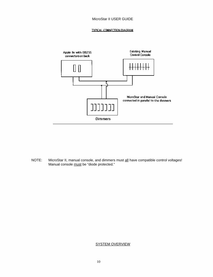
TYPICAL CONNECTION DIAGRAM
MicroStar II USER GUIDE
10
NOTE: MicroStar II, manual console, and dimmers must all have compatible control voltages! Manual console must be “diode protected.”
SYSTEM OVERVIEW
MicroStar II USER GUIDE
11
MASTER AND WORKING COPY DISKS
A standard 5.25 inch flexible disk is the primary storage media of the Microstar II. Each system comes with MASTER and WORKING COPY disks. The Master disk is used to make working copies of the MicroStar II program and is write protected against accidental erasure. The Working Copy disk may be used to review the MicroStar II program and record performances. SEVERAL COPIES OF THE MASTER DISK SHOULD BE MADE, AND THE ORIGINAL MASTER DISK STORED IN A SAFE PLACE. Blank 5.25 disks should be Apple IIe compatible soft-sectored 40 track. The method of making additional copies is described later in this section under: MAIN MENU - CREATE NEW DISK.
LOAD MicroStar II PROGRAM Insert the MicroStar II Program disk into the disk drive #1 with the label facing up. The Apple Computer is turned on, the data contained on the disk is loaded into RAM. The Apple Computer uses the data in RAM to run the MicroStar II Program. ONE Microstar II CARD MUST BE IN SLOT TWO. Turn the power on (power switch on the Apple Computer is located to on the ‘left back-panel’) and the disk in drive #1 will load automatically. The loading process will take about 35 seconds. The disk drive will not need to be accessed again except to save any program/cue changes before turning off the computer.
USING THE KEYBOARD
At this point, you should have become familiar with the Apple keyboard. If not, please use the Apple reference material to do so. A brief review of some of the keys will be presented before continuing. The CAPS LOCK key on the Apple IIe must be in the DOWN position at all times for proper operation. The <RETURN> key is pressed after the MicroStar II asks for an input such as passwords, date & time, or show title. If a flashing cursor is present, read the messages carefully. The normal action is usually to press <RETURN>. Pressing <RETURN> will become quite natural in a very short time. The MicroStar II has been designed so that every function is followed by the <RETURN>. This prevents accidental operation of an unintended command. In order to save steps during operation of the MicroStar II while loading or playing back information, the <RETURN> key may be turned off. The <RETURN> key can be disabled by using one of the command functions displayed on the screen in either New Production or Present Production. Also See: Recording and Playing Cues - Individual Functions, “R” - <RETURN>. The ESCAPE key is the key labeled “ESC”. The ESCAPE function is used whenever the user needs to ‘Back-out’ of the present function, hence the name ESCAPE. It may be used in the MAIN MENU as well as in the RECORD and PLAY modes. The Reset key, or CTRL Reset, when pressed, it will return the MicroStar II program to the beginning. The SAVE CUES FUNCTION MUST BE USED BEFORE RESETTlNG IF INFORMATION ENTERED FOR A PERFORMANCE IS TO BE RETAINED! Also See: Recording and Playing Cues - Individual Functions, “ ^ “ Saving Cues
MicroStar II USER GUIDE
12
RECORD AND PLAY PASSWORDS
There are two modes in which the MicroStar II can be used, RECORD and PLAY. The RECORD mode allows the user to access every function of the MicroStar II. The RECORD mode is used to Create disks, Change Passwords, and enter and modify data for performances. Cues are programmed and modified in the RECORD Mode. The PLAY Mode is used to simply play back the performance. Modifications to dimmer levels, fade rates, and labels cannot be made in the PLAY Mode. A system of passwords is used to limit access to the modes. A different password can be assigned to each mode. THE PASSWORDS ARE INITIALLY PRESET TO RESPOND TO THE <RETURN> KEY AND MAYBE KEPT THIS WAY IF PASSWORDS ARE NOT TO BE USED..
SPECIAL PASSWORDS
Special passwords are used to access the following utilities:
QUICK ACCESS TO CUE SCREEN
The word “QUICK”, entered before the RECORD or PLAY Password, (no spaces) will take the program directly to the Present Production-Cue Information Screen. The Main Menu, Show Title, and Date and Time will be bypassed.
CONTROL SPEED OF DIAGNOSTIC ROUTINE
The speed at which the Auto-Test feature of the Diagnostic Routine will run can be adjusted. Enter the password “DIAGNOSTIC”. This message will appear:
ENTER A NUMBER FROM (1-999) BELOW <LOW # = FAST> <HIGH # = SLOW>
PRESENT VALUE = I
Enter a larger number to slow down the rate during auto-test.
CONTROL MANUAL LOAD SAMPLING RATE
To control channel level fluctuations due to impure DC signals from secondary consoles during Manual Loads, set the sample rate to a slower speed. Enter the password, “LOAD MANUAL”. This message will appear’.
ENTER A NUMBER FROM 1-255 BELOW <LOW # = FAST> --- <HIGH # = SLOW>
PRESENT VALUE = 1
The rate is preset, for most accurate reading, at the fastest rate (1) at the factory.
MAIN MENU
The first screen after entering the password is the “MAIN MENU.” There are two menus, a “RECORD

MicroStar II USER GUIDE
13
MODE” and a “PLAY MODE” menu. The RECORD menu contains all seven (7) menu items. The PLAY menu contains only the first four (4).
“ESCAPE” functions will return to the MAIN MENU from the selected menu item. If the “ESC” key is pressed in the main menu, the program returns to ENTER RECORD or PLAY PASSWORD. Individual menu selections will be discussed in the order they appear in the Record Mode Menu.
RECORD MODE MENU
PRESS A NUMBER FROM I - 7
I PRESENT PRODUCTION 2 DIAGNOSTIC ROUTINE S PRINT CUE SHEET 4 MicroStar II TUTORIAL 5 NEW PRODUCTION 6 CREATE NEW DISK 7 CHANGE PASSWORDS
PLAY MODE MENU
PRESS A NUMBER FROM 1 - 4
I PRESENT PRODUCTION 2 DIAGNOSTIC ROUTINE 3 PRINT CUE SHEET 4 MicroStar II TUTORIAL
PRESENT PRODUCTION
The “PRESENT PRODUCTION” contains all data associated with the performance stored on disk. Cues are recorded and played in the Present Production. This menu selection will be discussed in detail in a later selection. Press menu item 2, DIAGNOSTIC ROUTINE if you do not wish to access the PRESENT PRODUCTION.
DIAGNOSTIC ROUTINE
The “DIAGNOSTIC ROUTINE” tests the output of each control channel. Each channel is brought from zero to full, one at a time. As the next channel is brought UP (full or ‘FF’) the previous channel goes to ZERO. By pressing the <RETURN> key, each channel may be tested individually. Stepping through the channels in this manner provides a convenient method for a lamp and focus check.
MicroStar II USER GUIDE
14
An automatic test can be started by pressing the “A” key. Each channel will be brought from zero to full and back to zero. The speed at which the Auto-test steps through channels can be adjusted. Also See: Special Passwords - Control Speed 0f Diagnostic Routine.
PRINT CUE SHEET
The “PRINT CUE SHEET” routine outputs all data associated with the PRESENT PRODUCTION to a printer. The Show Title, Channel Levels, Fade Rates, and Labels are printed for all cues and channels. Cue Sheets will print 80 columns wide. The recommended printer is the Apple Imagewriter II, a dot matrix printer. An Apple serial interface card in slot 1 is necessary.
MicroStar II TUTORIAL
The MicroStar II contains a built-in Owner’s Manual as a permanent aid to using the system. Items of interest can be selected from the TABLE OF CONTENTS displayed on the screen, and reviewed individually. By using the <RETURN> key, each “page” is shown in succession. To escape the TUTORIAL, press the “M” key and <RETURN). The program will then return to “ENTER PASSWORDS”. Enter the ‘Record’ Password to return to the MAIN MENU. To PRINT the TUTORIAL, press the “P” key and <RETURN>.
NEW PRODUCTION
Only one show consisting of 250 cues is stored on a disk. This set of cues is always in the “PRESENT PRODUCTION.” “NEW PRODUCTION” provides a convenient method of ‘erasing’ the data associated with the “PRESENT PRODUCTION”. All channel levels, fade rates, and labels previously programmed will be cleared, the disk may then be used to program another production. A “LAST CHANCE” message will appear in “NEW PRODUCTION” to avoid accidentally erasing the “PRESENT PRODUCTION.” (The “PRESENT PRODUCTION” is actually not erased on disk until the “SAVE CUES” function is activated.)
CREATE NEW DISK
The “CREATE NEW DISK function is used to make additional copies of the Master Disk or to make back-up copies of existing productions. It is advisable to make several ‘working” copies of the MicroStar II program from the write protected Master Disk as one of the first steps in setting up and using the system.

MicroStar II USER GUIDE
15
The Master Disk should then be stored in a safe place. BACKUP COPIES OF CURRENT PRODUCTIONS SHOULD BE MADE IN CASE THE ORIGINAL IS DAMAGED OR LOST ! Only one disk drive is required to make copies, however, two drives will greatly reduce the copy time. After selecting the “CREATE NEW DISK” function from the MAIN MENU, an introductory message appears on the screen. The next step is to specify the location of the Disk Controller Card and the number of drives to be used. The copy program assumes that the Controller Card is in slot 6, and that TWO disk drives are to be used. If two disk drives are to be used, input information as follows: Original Slot: Default = 6 (press the <RETURN> key)
Drive: = I (press the <RETURN> key) Duplicate Slot: Default = 6 (press the <RETURN> key) Drive: Default = 2 (press the <RETURN> key)
The message “PRESS <RETURN> KEY TO BEGIN COPY” appears. At this point, the program will give all necessary instructions to copy the disk. When ONE disk drive is used, the original disk and the duplicate disk must be “swapped” eight different times.
CHANGE PASSWORDS
Passwords are used to limit access into the MicroStar II program. A separate password can be
entered for both the RECORD and PLAY modes. Data for a performance can be recorded, modified, played and deleted in the RECORD mode performance can be played back in the PLAY mode, with
operator control over fade rates and cue sequence. Previously recorded data such as dimmer levels and programmed fade rates cannot be recorded, modified, or deleted in the PLAY mode.
If access into either of these modes is to be Imitated, enter the desired password(s). MAKE SURE THE PASSWORD(S) WILL NOT EASILY BE FORGOTTEN. If no password is to be used, change the password to a “none-used” status by pressing the <RETURN> key instead of entering a word. The password will now be the normal action of pressing the <RETURN> key only when asked to enter password. IF THE RECORD PASSWORD IS FORGOTTEN, CONSULT Dimmer Ideas FOR THE MASTER PASSWORD.
PRESENT PRODUCTION SELECTION
A performance is recorded, and may be played back, in the RECORD mode of the MicroStar II program.
MicroStar II USER GUIDE
16
After entering the RECORD Password, select MAIN MENU item 1- PRESENT PRODUCTION, by pressing the numeric key #1. Note: If a printer is connected, and is NOT to be used to PRINT CUE SHEETS, it should be turned OFF before continuing. If a printer is not connected, simply disregard the “Turn Off Printer” message and beep.
PRESENT PRODUCTION SHOW TITLE
A title for the performance can be entered, and will be displayed on screens associated with the Present Production, and printed on cue sheets. Press the “R” key and type in a title of up to 34 characters. After entering the title, press the <RETURN> key and the title will be displayed. If no title is desired, simply press the <RETURN> key to continue.
ENTERING DATE AND TIME
A date can be entered to indicate the most current day on which the performance was accessed. Type in the month, day, and year (ie. 12/31/99) and press the <RETURN> key. (The ‘slashes’ are entered automatically for you). The MicroStar II has an internal clock which is displayed on the screens associated with the Present Production. The current time is entered in hour and minute format (ie. 12:00). (The ‘colon’ is entered automatically for you). After the time has been entered, press the <RETURN> key.
If no date or time is to be entered, press the <RETURN> key. The date will default to 00/00/00; the time display will default to 12:00 and start at that point. After pressing the <RETURN> key the last time, the PRESENT PRODUCTION will be loaded into the Apple from the disk drive. (A brief message “BREAK A LEG”, will appear at this time.)
SCREENS
There are three screens which can be displayed in the Present Production. The first screen shown is the CUE INFORMATION SCREEN. The second screen CHANNEL LEVELS SCREEN, and can be viewed by pressing the <SPACE BAR>. Then <SPACE BAR> is pressed a second time, the CUE INFORMATION SCREEN will be displayed again. The third screen is the CHANNEL INFORMATION SCREEN, and is displayed when using the “ I” INFORMATION command (to be discussed later). There are several elements common to each screen. A complete operating, or Command, menu is displayed in a vertical column along the right side of all screens. The date and time are shown at the top of the screen. The show title is given on the next line down. At the bottom left of each screen, the cue numbers and fade rates of the stage cue and next cue are displayed. Directly above this, along a horizontal line is a list of Special functions. Note that these functions are different from the CUE INFORMATION and CHANNEL LEVELS screen. The area in the bottom right of screen is reserved for prompt messages and data entry. The individual Command and Special function will be discussed in a later section.

MicroStar II USER GUIDE
17
CUE INFORMATION SCREEN
The CUE INFORMATION SCREEN displays a sequence of six cues. The LAST cue, STAGE cue, NEXT cue, and three pending cues are shown, along with their cue numbers, fade rates, and labels (cue information). The STAGE cue fader is identified by an inverted horizontal bar and the letter “X”. The NEXT cue fader contains a fade-out rate for the previous stage cue it is replacing (Fade “X” DN). Fade-in and Fade-out rates are assigned in the “Y” NEXT cue fader. For instance, cue number two contains the fade OUT rate (Fade “X” DN) for cue number one, and the fade IN rate (Fade “Y” UP) for itself. An eleven character label can also be attached to each cue to add clarity to the cue information. Labels are assigned by using the “I” INFORMATION command. Fade rates are discussed further in the sections; INDIVIDUAL FUNCTIONS, “T” TIME and REFERENCE OF COMMANDS- SETTING FADE RATES. Press the <SPACE BAR> to toggle to the CHANNEL LEVELS SCREEN.
CHANNEL LEVELS SCREEN
The CHANNEL LEVELS SCREEN displays control channels and their associated output levels. The maximum system configuration will be displayed regardless of the size of the system installed. Channel levels are shown to the right of each channel. Levels are listed in terms of percentage from 0 to 100%. Zero is indicated by --, while full is FF. All other levels have a numeric value. Levels may be set for an individual channel, ranges of channels in sequence, or groups of channels not in sequence. Levels may be entered from the keyboard by using the “L” LEVEL% command, or from another console by the “M” MANUAL command. Setting levels is further discussed in the sections; INDIVIDUAL FUNCTIONS, “L” LEVELS, MANUAL and REFERENCE OF COMMANDS - SETTING LEVELS. Press the “I” key to view the CHANNEL INFORMATION SCREEN.
CHANNEL INFORMATION SCREEN
The CHANNEL INFORMATION SCREEN displays control channels along with an associated label. When the “I” INFORMATION command is used in the CHANNEL LEVELS SCREEN, the CHANNEL INFORMATION SCREEN is automatically displayed. The CHANNEL INFORMATION SCREEN is only accessed from the CHANNEL LEVELS SCREEN. The maximum system configuration is displayed regardless of the size of the system installed. Any meaningful label can be entered for each channel (within the constraints of the size of the 5 character field) During the process of entering levels, the CHANNEL LEVELS SCREEN and CHANNEL INFORMATION SCREEN can be toggled by using the <SPACE BAR>. The CHANNEL INFORMATION SCREEN adds clarity to the channels and the
MicroStar II USER GUIDE
18
respective instruments they control. Channel labels are further discussed in the section; INDIVIDUAL FUNCTIONS, “I” INFORMATION. Press the <SPACE BAR> to return to the CUE INFORMATION SCREEN.
SYNTAX
Syntax is the term used to describe the proper format of data entry. An error message will occur if illegal entries are made. Numeric characters, rather than alpha characters, must be entered when called for. Entries must be within the constraints of the system configuration. For instance, the MicroStar II has a maximum of 96 control channels. Entering levels for channel 98 would not be allowed.
Proper syntax must also be used when entering Ranges (From/Thru) and Groups (And) of channels and cues. Ranges are always in sequence. Range, or From/Thru commands, are achieved by the use of two periods (..) between the first and last numbers in sequence. Example: Cues 5..12 Cues 5 thru 12 will contain identical data. Group, or And commands, are achieved by the use of comma (,) or dash (-) between the numbers. Example: Cues 5, 7, 12 Cues 5 and 7 and 12 will be dealt with separately. Example: Cues 5-7 Cues 5 and 6 and 7 will be dealt with separately.
RECORDING AND PLAYING CUES
OVERVIEW OF CUES
MicroStar II USER GUIDE
19
Cues are designed and modified in the PRESENT PRODUCTION. Up to 250 cues may be recorded per disk, containing output levels for a maximum of 96 channels. Each cue is identified by a unique number, and any number between I and 999.9 may be assigned. There are also 10 special cues ‘below’ cue 1 (0 to .9) called QUICK CUES. 0f these 250 cues, there are 200 whole number and 50 possible Point cues. Point cues are inserted between any whole number. Between the whole numbers 1 and 2, there are up to NINE insertable cues; 1.1, 1.2, 1.3, 1.4, 1.5, etc.. Cues contain the level settings for up to 96 control channels. Levels are assigned from zero to 100% in 1% increments. Zero is identified by -- and 100% or full is FF. Cues always execute in sequential order. The transition from cue to cue is achieved by assigning a time for the STAGE CUE (X fader) to fade OUT and the NEXT CUE (Y fader) to fade IN, and starting the transition with the ”F” key.
QUICK CUES
Point cues may be inserted between any whole number cue. There are 10 possible point cues below cue number one. These cues 0, .1, .2 through .9, are called QUICK CUES. QUICK CUES may contain channel level settings and crossfade times like other cues. However, QUICK CUES can be inserted into the cue sequence at an time by simply pressing the appropriate numeric key (0 - 9). When the numeric key for any QUICK CUE is pressed, that cue is automatically inserted into the NEXT CUE (Y) fader. When the <RETURN> key is pressed, the cue will fade IN to the STAGE CUE (X) position. If the <RETURN) key is ‘OFF’, the QUICK CUE will begin to fade IN to the STAGE CUE (X) position, at its assigned rate, immediately. NOTE: New MicroStar II users have a tendency to press a ‘numeric’ key instead of an ‘alpha’ command key, accidentally activating a QUICK CUE. Catastrophic results during a live show can be avoided (if QUICK CUES are NOT being used) by entering fade times for all the QUICK CUES of 9999 seconds. Thus if a QUICK CUE is accidentally activated the stage picture will not change significantly before corrective action is taken. The corrective action in this case is to press the “<--” left arrow key, REVERSE SEQUENCE, which cancels the active crossfade and puts the precious STAGE CUE back on stage. Also See: Individual Functions - “R” + or - Return
“L” Levels “T” Time XY
SETTING LEVELS Channel levels are set from the keyboard or from a secondary console. The value is displayed on the CHANNEL LEVELS SCREEN. The CHANNEL INFORMATION SCREEN allows labels to be attached to control channels to aid in keeping track of, for example, external dimmer to instrument patches.
MicroStar II USER GUIDE
20
Also See: Individual Functions - “L” Levels “M” Manual Load “I” In formation Screens - Channel Levels Screen Channel Information Screen Syntax - Range (or From/Thru) commands Group (or And) commands
SETTING LEVELS BLIND
Channel levels may be set in cues other than the Stage Cue without effecting the stage. Blind records must be made from the keyboard. Also See: Individual Functions - “L” Levels Syntax - Range (or From/Thru) commands Group (or And) commands
SETTING FADE RATES Fade-in and Fade-out rates are contained in the Next Cue “Y” fader. Separate rates may be assigned to each fader (“split fades”). Manual control over crossfades is achieved through the Manual Crossfade Option. Also See: Individual Functions - “T” Time XY Syntax - Range (or From/Thru) commands Group (or And) commands Special Features - Manual Crossfades
PLAY-BACK OF CUES Timed crossfades are played back from the keyboard. Timed crossfades may be started by the Fade (“F”) key on the keyboard, or a Fade key in a remote location. An active crossfade may be Speeded Up, Slowed Down, Held, advanced Forward and Reverse. The Crossfade may be Blacked Out and Restored at a later time . Also See:

MicroStar II USER GUIDE
21
Individual Functions - “F” Fade X’( Cues “Speed Up/Slow Down “H” Hold XY Cues “)” Sequence Forward “->“ Cues “<“ Sequence Reverse “ <-” Cues “B” Blackout Cues Special Features - Remote Fades
BLIND CHANGES OF FADE RATES Fade rates may be modified for any cue. Fade rates may not be modified during an active crossfade, except for the playback functions which effect the programmed rate of the XY crossfade. Also See: Individual functions - “T” Time XY “H” Hold XY
CHANGE CUE SEQUENCE
The order of execution of cues into the Stage Cue (X) or Next Cue (Y) faders can be changed. A New Stage Cue can be entered at any time, except during an active crossfade. Any cue, range, or group of cues may be deleted. Also See: Individual Functions - “Q” Stage Cue “N” Next Cue “D” Delete Cues Syntax - Range (or From/Thru) commands Group (or And) commands
INSERT CUES WITHIN SEQUENCE
Up to 9 point cues may be inserted between whole number cues. Cues below cue 1 (0 to .9) are Quick cues, and may be inserted at any time into the Next Cue “Y” fader. Quick cues are assigned to the numeric keys (0 - 9). Also See: Individual Functions - “N” Next Cue “Q” Stage Cue Overview of Cues - Quick Cues

MicroStar II USER GUIDE
22
EFFECTS
Any sequence of cues may be chased from 1 to 9999 times. Additive cues may be Piled-On to stage. Cues may also be synchronized to an audio source. Also See: Individual Functions - “0” Looping Cues “P” Pile-On Cues Special Features - Tone Cues
QUIT PROGRAM
After programming any cue/s, the Present Production MUST BE SAVED TO DISK for permanent storage. THE DATA WILL BE LOST IF THIS IS NOT DONE. A special QUIT feature is provided to increase access speed back into the program. Also See: Individual Functions - “^” Save Cues Special Features - Exit Program

MicroStar II USER GUIDE
23
REFERENCE OF COMMANDS
INDIVIDUAL FUNCTIONS
An operating, or command, menu is displayed along the right side of each screen in the PRESENT PRODUCTION. The appropriate key used to operate the function is displayed in an inverted line to the left of the command. For example, to initialize a crossfade, the “F” “Fade XY” key on the Apple keyboard is pressed. It is necessary to ‘back out’ of a command, by using the Escape <ESC> key, before a new command can be executed. The Individual Functions will be discussed in the order they appear on the screen.
“R” + or - RETURN
The use of the <RETURN> key indicates the completion of an entry. For instance, after selecting an item in the command menu such as “F” Fade XY, the <RETURN> key must be pressed before the program will continue. In the MicroStar II the <RETURN> key serves an additional purpose. It helps prevent the accidental operation of an unintended command such as “F” Fade XY or “B” Blackout. By pressing the appropriate key for a command such as “F” Fade XY, the MicroStar II is placed in a “ready” position. Nothing will happen until the <RETURN> key is pressed. The <RETURN> key is equivalent to a “go” command. Note that “R” RETURN is the first command displayed in the command menu. The + means that the <RETURN> key is activated and must be used. The <RETURN> key can be turned OFF by pressing the “R” key. When the “R” key is pressed the command will read “R” - RETURN”. This indicates that the <RETURN> function is not activated. Each time the “R” key is pressed, the message “TURN ON/OFF <RETURN> appears in the prompt area of the screen. Turning the <RETURN> function off increases programming speed. However, care should be taken when playing cues to avoid accidents.
MicroStar II USER GUIDE
24
“ >“ SEQUENCE FORWARD “-->“ CUES
The Sequence Forward (--> SEQ + Q) function instantly advances to the next cue in sequence without fading. The Right Arrow key (-->) activates the Sequence Forward command. When the Right Arrow key is pressed, the message ADVANCE SEQUENCE TO CUE (the NEXT cue number) will appear in the prompt area. The Next Cue will appear on stage when the <RETURN) key is pressed. If the <RETURN> key is OFF, the next cue will immediately “bump” on stage. During an active crossfade this command will cancel the fade and instantly go to the next cue. When the Right Arrow (-->) key is held down for more than a second, on the Apple IIe the “auto-repeat feature” is activated and the cues will “scroll”. On the Apple II Plus, the Repeat “REPT” key must be held down in conjunction with the Right Arrow ( -->) key. The Sequence Forward function can also be activated from a remote location and is part of the optional manual crossfader unit.
“<“ SEQUENCE REVERSE “ <--” CUES The Sequence Reverse (<-- SEQ - Q) function works the same as Sequence Forward, except in reverse. The cue will reverse, without fading, to the previous Stage Cue. The Left Arrow “<--” key activates the Sequence Reverse function. When the Left Arrow (<-- ) key is pressed, the message “REVERSE SEQUENCE TO (the ‘previous’ cue number)” will appear in the prompt area. During an active crossfade, this function will instantly reverse the cue back to its original starting point.
“B” BLACKOUT
The BLACKOUT (B BLACKOUT) function instantly sets the output of ALL control channels at ZERO. The BLACKOUT command may be used at any time before, during, or after a crossfade. The “B” key operates the BLACKOUT command.
MicroStar II USER GUIDE
25
When the “B” key is pressed, and the <RETURN> key is activated, the message, “BLACKOUT THE STAGE CUE - (the present stage cue number)” will appear in the prompt area. When the <RETURN> key is pressed, BLACKOUT will flash in the Command Menu, and the message, “PRESS B” TO RESTORE CUE” will appear in the prompt area. THE “B” KEY MUST BE PRESSED AGAIN TO RESTORE THE STAGE CUE. If the <RETURN> key is OFF, the cue will be blacked out immediately. When the STAGE CUE is restored, the current outputs of all control channels will be ON stage. The output levels may be reviewed in the CHANNEL LEVELS SCREEN.
“C” COPY CUES
The COPY CUE function (COPY Q) is used to load the channel levels contained in the STAGE CUE into any other cues. When the “C” key is pressed and <Return>, the message, ‘ENTER CUE/S:” appears in the prompt area. Any cue, range of cues, or group of cues may be entered. Fade Rates and Cue Labels are NOT copied. Note that a cue must be on stage before it can be copied.
“D” DELETE CUES
The DELETE CUES function (D DELETE) deletes cues from memory. When the “D” key is pressed, and <RETURN>, the message, “ENTER CUE/S:” appears in the prompt area. Any cue, range of cues, or group of cues may be entered. The DELETE command is used to add to the bank of insertable point cues available. There are 200 cues plus 50 point cues, per disk. To make more than 50 point cues available, some whole number cues must be deleted. The DELETE command only deletes RAM “random-access-memory”. Deleted Cue information previously SAVED TO DISK may be restored by reloading the PRESENT PRODUCTION. A deleted cue can be retrieved by “L” (Levels) Command for that cue. It will go back into its proper sequence. Misc. See: “^” SAVE CUE command
“F” FADE XY CUES
The Fade Cues (F FADE XY) command is used to initiate a crossfade. When the “F” key is pressed, and <RETURN>, the fade will start. The message, “BEGIN CROSSFADE TO NEXT CUE - (the NEXT cue number)” will appear in the prompt area. It is the equilivant of a “GO” button or command. Timed crossfades take place as programmed unless their rates are altered by the following playback commands: SPEED UP TIMED CROSSFADE RATE The “>” (’Greater Than’ key; no SHIFT required) speeds up the rate of the XY crossfade. SLOW DOWN TIMED CROSSFADE RATE The “<“ (‘Less Than’ key; no SHIFT required) slows down the rate of the XY crossfade. RESTORE TIMED CROSSFADE RATE TO NORMAL The “=“ (‘Equals’ key) returns the crossfade to the

MicroStar II USER GUIDE
26
programmed rate or ‘real time’ in seconds. Note: Speed Up and Slow Down functions provide only ONE degree of increase or decrease. Holding the keys down will neither increase or decrease the rate by more than ONE degree. HOLD TIMED CROSSFADE The “H” key stops the active crossfade RESTARTING A HELD TIMED CROSSFADE The “F” key starts the crossfade from the Hold position. Crossfades may be advanced instantly by SEQUENCE FORWARD “--> SEQ + Q” or reversed instantly by SEQUENCE REVERSE “ <--SEQ - Q” , the right and left arrow keys respectively. Remember the Shift key is NOT required to use <, >, or = keys. The Fade Cue “F” function is used to start a Manual Crossfade when that component is used. The Fade Cue function may be activated from a remote location and is part of the optional manual crossfader unit.
“H” HOLD FADE
The Hold Fade (H HOLD XY) function stops an active crossfade. If the “H” key is pressed during an active crossfade the message, “HOLD active CROSSFADE PRESS F. <, > TO CONTINUE” will appear in the prompt area. The crossfade may be continued by pressing; the “F” key “Fade XY”, reversed instantly by “<-- SEQ-Q” , or advanced instantly by “--> SEQ + Q”. Note that “,” does not to be pressed. The optional FADE or GO button will not release the HOLD function. The BLACKOUT, Pile-On Cues, and Manual Load functions are active while a crossfade is on Hold. The Manual Load function can be used to load the stage image into another cue, range of cues, or group of cues while a crossfade is on HOLD. The active channel levels will be copied into those cues. The Manual Load function is discussed in the section, “M” Manual Load.
“I” INFORMATION (LABELS)
The Information (I INFO) function is used to assign a label to Cues and Channels. The labels are intended to add clarity to the Cue Screen, and aid in setting channel levels. When the “I” key, and <RETURN>, is pressed in the Cue Screen, the message, “ENTER CUE/S:” appears in the prompt area. Any cue, range of cues, or group of cues may be entered. Press <RETURN>. The message, “ENTER INFO:” will appear. An 11 character label for the cue/s selected may be entered from the keyboard.

MicroStar II USER GUIDE
27
When the “I” key, and <RETURN>, is pressed in the CHANNEL LEVELS SCREEN, the CHANNEL INFORMATION SCREEN will appear. The message, “ENTER CHANNEL/S:” will appear in the prompt area. Any channel, range of channels, or group of channels may be entered. Press <RETURN>. A five character label for the channel or channels selected may be entered from the keyboard.
“L” LEVELS The Levels (L Level%) function is used to assign channel levels. Then the “L” key and <RETURN>, is pressed the CHANNEL LEVELS SCREEN is displayed. The message “ENTER CUE/S:” will appear in the prompt area. Any cue, range of cues, or group of cues maybe entered. Press <RETURN>. The message, “ENTER CHANNEL/ S:” will appear in the prompt area along with the channel number or numbers which have been selected. If a RANGE of channels has been selected, by using the THRU “..” (period period) command, all channels within that range will receive the same level setting. If a GROUP of channels has been selected, by using the AND “,” (comma) or “-” (minus or dash) commands the first channel in that group will be displayed. Levels will be set for each channel individually. Levels are entered as a percentage of 100% which is Full. Zero is represented by “--” (dash dash or minus minus), while Full is represented by “FF”. After entering a level, by using the numeric keys, press <RETURN>. The level entered will be displayed by the appropriate channel or channels. The message, “ENTER CHANNEL/S:” will appear in the prompt area. Adjustments in level settings may now be made for any channel, range of channels, or group of channels. In addition to typing in a level percentage, levels may be adjusted by use of the Plus “+” and Minus “-” keys. Enter the Channel(s) for which levels are to be modified. Press the Plus “+” key twice, and the level(s) will move up one percentage. Each time the Plus “+” key is pressed thereafter, the level(s) will increase one percent. If the Plus “+” key is held down for more than two seconds on the Apple IIe, or by using the Repeat “REPT” key on the Apple II Plus, the levels will scroll up in one percent increments until the key is released. The same applies to the Minus “-” key in reverse. Levels will be decreased. Channel levels may also be modified by entering a plus or minus percentage. Enter the Channel(s) for which levels are to be modified. Press the Plus “+” key (the shift key is not required). A Plus “+” sign will appear in the prompt area. Enter the percentage that the level is to be increased. This percentage value is represented in terms of 100% not as a percentage of the current level setting. Press <RETURN>. The new level settings will be displayed. The levels of all active channels in a cue may be proportionally raised or lowered. Channels which have a value of zero “--” will NOT be effected. Enter the cue or cues for which levels will be proportionally modified. Enter all channels to be modified by using the Thru “. .” (period period) command, such as 1..64. The Plus “+” , Minus “-” and +/- Percentage (by entering a NUMBER directly after the “ + “ or “ -” ) commands may be used to modify the cue. Channel levels may be set or modified for cues other than the stage cue without effecting the stage thus, “Blind Record”. Simply enter a cue number other then the STAGE CUE. The CHANNEL LEVELS SCREEN will display the channels associated with that cue. Levels may not be changed during an active crossfade. The CHANNEL INFORMATION SCREEN can be used to help keep track of what the channels are
MicroStar II USER GUIDE
28
controlling. When entering no channel or levels the <SPACE BAR> can be used to toggle to the CHANNEL Information SCREEN. NOTE: TO EXIT the “L” LEVELS command, press the <ESCAPE> key. This is the only command that requires this action.
“M” MANUAL LOAD The Manual Load (M MANUAL) function allows channel levels to be set from an external console. When the “M” key and <RETURN>, is pressed, the CHANNEL LEVELS SCREEN is displayed. The message, “ENTER CUES/S:” will appear in the prompt area. Any cue, or group of cues maybe entered. Press <RETURN>. The message “SET MANUAL CONSOLE” will appear in the prompt area. Levels for any channel, range of channels, or group of channels may then be set on the external console. As channel levels are set on the external console, their values will be displayed on the CHANNEL LEVELS SCREEN. After all levels have been set, press the <RETURN> key. All channel levels are now stored for the cue or cues selected. The MicroStar II will read and record its own output levels. An active crossfade may be held. “H HOLD XY”, at any point, and the output levels of control channels loaded into any other cue or cues using the manual load function. When setting levels from a secondary console, the levels displayed for control channels may fluctuate one or two percent, causing a flicker on the screen. This is because the signal coming from the secondary console is not pure DC (the Microstar II is reading the high and low ends of the wave). To correct this the sampling rate of the Manual Load function can be changed. It is necessary to return to the beginning of the MicroStar II program to enter the “Special Password” “LOAD MANUAL” to access the utility for changing the sampling rate. BE SURE TO USE THE SAVE CUES “^ SAVE Q” function described later in this section to save any information previously entered, but not saved to disk. Also See: Special Passwords - Control Manual Load Sampling Rate
“N “ NEXT CUE
The NEXT CUE (N NEXT Q) function is used to enter a new cue into the “Y” or NEXT CUE fader. When the “N” key is pressed, and <RETURN>, the message, “ENTER CUE:” appears. In the prompt area. Any existing or new cue number maybe entered. Cues maybe inserted between whole numbers by the NEXT CUE function. For instance, cue 1.5 may be selected as the new NEXT CUE between cues 1 and 2. When a new NEXT CUE is selected, the cues after that cue will be displayed in sequential order.
“0” LOOPING CUES
MicroStar II USER GUIDE
29
The Looping Cues (O LOOP Q*) function allows the automatic execution of sequential cues. When the “O” key is pressed and <RETURN>, the message, “ENTER CUES:”, will appear in the prompt area. Any cue or range of cues maybe entered. Press <RETURN>. The message, “FOR CUES:” (the cues entered are displayed, “ENTER # OF LOOPS:” will appear in the prompt area. Any number of loops from 1 to 9999, maybe entered using the “THRU” (period period) command. A Cue Loop is assigned by entering the beginning and ending cues, and number of loops. An asterisk “*” will be displayed in the Cue information Screen by the cue number of all cues which are part of a loop. When a Cue Loop is started, crossfades between those cues within the loop will continue automatically until the loop count is zero. Upon completion of the assigned number of loops, a Crossfade will be made to the next cue outside of the loop sequence. For example, if a loop is assigned for cues 1..10, a crossfade will be made into cue 11 upon completion. The Fade key “F” will then be used to execute the next crossfade . There may be more than one loop contained in a Present Production. Individual loops must be separated by at least one cue which is NOT part of a loop cue. A Loop may be Held “H HOLD XY”, Instantly Advanced “SEQ + Q” or Instantly Reversed “SEQ - Q”. If the Fade key “F” is pressed during an active Cue Loop, the loop count will be reduced to one and the loop will be complete on the last cue within the loop. A loop may be deleted by entering a loop count of 0 (zero) for those cues within the loop.
“P” PILE-ON The Pile-On (P PILE-ON) function adds the channel outputs of the cue or cues contained in the NEXT CUE fader to the image contained in the STAGE CUE fader. The Pile-On function is strictly additive. When the “P” key is pressed and <RETURN>, the combined output if all control channels will be added into the STAGES CUE until Pile-On is released. If channel levels are the same in cues being Piled-On to Stage, no change will take place. Outputs for control channels which are greater than those contained in the STAGE CUE fader will be added and displayed in the CHANNEL LEVELS SCREEN. Cues will continue to Pile-On until the mode is released by pressing the “P” key again.
“Q STAGE CUE
The STAGE CUE (Q STAGE CUE) function is used to enter any new cue into the STAGE CUE fader.

MicroStar II USER GUIDE
30
When the “Q” key is pressed, and <RETURN>, the message, “ENTER CUE :” will appear in the prompt area. The selected cue will come on the stage immediately. The STAGE CUE Function can also be used to create NEW cues. Cues may be inserted between whole numbers by the STAGE CUE function.
“T” TIME XY The Time XY (T TIME XY) function is used to assign fade rates for the STAGE CUE “X” and NEXT CUE “Y” faders. When the “T” key is pressed, and <RETURN>, the message “ENTER CUES/S:” will appear in the prompt area. Any cue, range of cues, or group of cues maybe entered. Press <RETURN>. The message, “TIME OF X IN SECONDS TO FADE STAGE Q DOWN :” will appear. Any fade rate from .1 seconds to 9999 seconds (or zero) may be entered. Press <RETURN>, the message, “TIME OF Y IN SECONDS TO FADE NEXT Q UP” will appear. Any fade rate from .1 seconds to 9999 seconds (or zero) may be entered. Fade rates above 100 seconds cannot contain 1/10 second increments. The NEXT CUE “Y” contains the Fade Out “FADE X DN” rate for the STAGE CUE and the Fade in “FADE Y UP” rate of itself. When using the optional Manual Crossfade unit, the letters “MAN” must be entered for fade times. The XY crossfade may be manual or split with half timed and half manual .
“ ^ ” SAVING CUES The Saving Cues “^ SAVE Q” function is used to save the Present Production to disk. THE ^ SAVE FUNCTION MUST BE USED AFTER INFORMATION HAS BEEN ENTERED OR MODIFIED, OR THE DATA WILL BE LOST! When the Shift Key and Carot “^” (above the “6” key on the Apple IIe and above the “N” key on the Apple II Plus) key are pressed simultaneously, the message, “SAVE MEMORY TO DISK” will appear in the prompt area. Press <RETURN>. All data will be transferred and SAVED to the disk. IT IS A GOOD IDEA TO USE THE SAVE CUES FUNCTION PERIODICALLY WHEN RECORDING CUES TO PREVENT LOSS OF DATA DUE TO POWER INTERRUPTION, ACCIDENT, ETC.
RESET TO CUE ONE The program can be reset to cue number one at any time. Press the <CONTROL> and “P” keys (or the ‘open Apple key only on the Apple IIe) and cue number ONE will appear in the STAGE CUE fader. The reset Feature is also used for Tone Cues and in the Remote Fade Option.
QUITTING THE MicroStar II PROGRAM When you are finished using the MicroStar II program simply press the <CONTROL> and “Q” keys to exit the program from the Present Production. REMEMBER TO SAVE CUES TO DISK (IF CUES ARE TO BE SAVED PRESS SHIFT/6) BEFORE QUITTING (CONTROL/Q) OR TURNING THE APPLE COMPUTER OFF !
MicroStar II USER GUIDE
31
TONE CUES/SYNCHRONIZING CUES TO A SOUND TRACK Crossfades maybe synchronized within an audio tape through the Tone Cue feature. A signal is generated and written to any unused track of a standard audio tape source. When the tape is played back, the signal will be read, and a crossfade initiated. A second signal will reset the program to cue number one. Two audio phone jacks located on the backplane of the Apple provide access to transmitting and receiving signals. Two standard 2 conductor I/8” miniature phone plugs will match the input/output jacks on the back of the Apple (Radio shack #274-236 or equivalent). The input/output plugs into the audio source must be connected correctly. Solder the two sets of plugs to the desired length of cable. Connect the inputs and outputs. The <CONTROL> and “R” keys will reset the program to cue number one and send a signal out to the tape. The “F” Fade XY Cues command will initiate a crossfade and send a signal out to the tape . Make sure that the cues are synchronized to the beginning of the tape by sending a Reset (t cue one) signal first. In the PRESENT PRODUCTION start the audio tape near the point where the first crossfade is to occur. Press the <CONTROL> and “R” keys. This will reset the program to cue number one and send the reset signal to the track used for tone cues. This track has to be unused. When played back, the program will always start at cue number one. At each point in which a crossfade is to occur, press the “F” Fade XY key. A signal will be sent to the audio track each time the “F” key is pressed. When played back, a crossfade will occur at each of these points. To reset the program back to cue number one, press <CONTROL> and “R” keys at the end of the cue sequence. The chase function “0” Looping Cues can also be incorporated into the Tone Cue function. For rapid chase sequences, start the loop with the “F” key. THE TONE CUE FEATURE IS ONLY AVAILABLE FOR APPLE COMPUTERS WITH 64K OF MEMORY. The Apple IIe is a 64K computer, while the Apple II Plus requires an additional 16K RAM “random-access-memory” card.
SOUND ON/OFF The sounds (clicks and beeps) associated with use of the program may be disabled in the Present Production. Escape any command previously selected, and press the <CONTROL> and “S” keys. Pressing the keys will toggle the sound back on again.
LOADING ADDITIONAL CUES An additional Program disk may be loaded while holding the STAGE CUE. Remove the original Program disk and insert the next disk. Press the <CONTROL> and “L” keys. An additional 250 cues will be loaded. Cue number one will come on to stage in approximately 15 seconds. IT IS NECESSARY TO MATCH THE LEVELS OF THE LAST CUE ON THE ORIGINAL DISK WITH

MicroStar II USER GUIDE
32
THE LEVELS OF THE FIRST CUE ON THE NEXT DISK, SO THE STAGE IMAGE WILL NOT CHANGE.


