JPL Publication 90-45 ==_= _ ,_" _ / /,j _ - c /?_J i / ,.y o¢/ , s: _i Microstrip Reflectarray Antenna for the SCANSCAT Radar Application John Huang I=.._ (NASA-CR-190453) MICROSTRIP REFLECTARRAY ANTCTNNA FOR THE SCANSCAT RADAR APPLICATION (JPL) 41 p G3132 N92-27463 Un¢las 0104051 November 15, 1990 National Aeronautics and Space Administration Jet Propulsion Laboratory California Institute of Technology Pasadena, California ! https://ntrs.nasa.gov/search.jsp?R=19920020220 2018-05-21T13:48:17+00:00Z
Transcript
JPL Publication 90-45
==_= _ ,_" _ / /,j _ -c /?_Ji
/ ,.yo¢/
, s: _i
Microstrip Reflectarray Antennafor the SCANSCAT Radar Application
John Huang
I=.._
(NASA-CR-190453) MICROSTRIP REFLECTARRAY
ANTCTNNA FOR THE SCANSCAT RADAR APPLICATION
(JPL) 41 p
G3132
N92-27463
Un¢las
0104051
November 15, 1990
National Aeronautics and
Space Administration
Jet Propulsion LaboratoryCalifornia Institute of Technology
Microstrip Reflectarray Antennafor the SCANSCAT Radar Application
John Huang
November 15, 1990
NASANational Aeronautics andSpace Administration
Jet Propulsion LaboratoryCalifornia Institute of TechnologyPasadena, California
The_researc]q desciibed in this pubqi_ w_scarried out by the J+t PropulsionLaboratory, California Institute of Technology, under a contract with the NationalAeronautics and Space Administration.
=
Reference herein to any specific commercial product, process, or service by tradename, trademark, manufacturer, or otherwise, does not constitute or imply itsendorsement by the United States Government or the Jet Propulsion Laboratory,California Institute of Technology. i
iE
m
i
|
|E
=-
ABSTRACT
This publication presents an antenna system that has been proposed
as one of the candidates for the SCANSCAT (Scanned Scatterometer)
radar application. It is the mechanically steered planar
microstrip reflectarray. Due to its thin, lightweight structure,
the antenna's mechanical rotation will impose minimum angular
momentum for the spacecraft. Since no power-dividing circuitry is
needed for its many radiating microstrip patches, this electrically
large array antenna demonstrates excellent power efficiency. In
addition, this fairly new antenna concept can provide many
significant advantages over a conventional parabolic reflector.
The basic formulation for the radiation fields of the microstrip
reflectarray is presented. This formulation is based on the array
theory augmented by the Uniform Geometrical Theory of Diffraction
(UTD). A computer code for analyzing the microstrip reflectarray's
performances, such as far-field patterns, efficiency, etc., is also
listed in this report. It is proposed here that a breadboard unit
of this microstrip reflectarray should be constructed and tested in
the future to validate the calculated performance. The antenna
concept presented here can also be applied in many other types of
radars where a large array antenna is needed.
-iii-
Microstrip Reflectarray Antenna
for the
SCANSCAT Radar Application
Table of Contents
I. Executive Summary ................. 1
II. Introduction ..................... 1
III. Description of the Microstrip Reflectarray ...... 3
IV. Application to SCANSCAT ............... 6
V. Analysis of the Microstrip Reflectarray ....... 7
VI. Advantages and Disadvantages of the Microstrip
Reflectarray .................... 12
VII. Conclusion ..................... 14
VIII. References ..................... 14
Figures .......................... 17
Computer Code ....................... 27
mL_.__ .IN'rE'NI'H)NXl_2_ RtA_-V-- PRECEDING PAGE BLANK NOT FILMED
E
I. Executive Summary
The mechanically steered flat microstrip reflectarray antenna
has been proposed as one of the candidate antennas for the SCANSCAT
(Scanned Scatterometer) radar application. Due to its thin, light-
weight structure, the antenna's mechanical rotation will impose
minimum angular momentum for the spacecraft. Since no power
dividing circuitry is needed for its many radiating microstrip
patches, this electrically large array antenna demonstrates
excellent power efficiency. As will be described in this report,
this fairly new antenna concept can provide many significant
advantages over a conventional parabolic reflector.
The tasks that have been completed this year are the basic
formulation of the antenna radiation fields and the generation of
a computer code for analyzing the microstrip reflectarray's
performances, such as far-field patterns, efficiency, etc. The
formulation is based on the array theory augmented by the Uniform
Geometrical Theory of Diffraction (UTD). It is proposed here that
a breadboard unit of this microstrip reflectarray should be
constructed and tested in the future to validate the calculated
performance. This antenna concept can also be applied in many
other types of radars where a large array antenna is needed.
II. Introduction
i. Antenna Requirements:
The Ku-band SCANSCAT antenna is required to generate two sets
of pencil beams, as shown in Figure I, to map the surface of the
Earth for scatterometer application. One set should radiate at 36 °
from the nadir direction, while the other should be pointed at 49 °
from the nadir. Both sets of beams should be able to transmit and
receive horizontally polarized electrical fields. Due to the
azimuth scan speed of 16.4 rpm for the mechanical platform and
relatively slower radar pulse return time, the transmit and receive
-i-
beams at 36 ° elevation need to be separated in azimuth by 0.59 °
similarly, the transmit and receive beams at 49 ° elevation should
be separated by 0.77 ° in azimuth. Consequently, a total of four
beams are to be generated at the frequency of 13.995 GHz. Each
beam needs to have a 3-dB beamwidth of not more than 0.7 ° with a
peak gain of 47 dBi or more and sidelobe level not higher than
-20dB.
2. Previously Proposed Concepts:
A previously proposed antenna system was a mechanically steered
dual-reflector configuration as illustrated in Figure 2, This
configuration, although simple in design and relatively low in
cost, will require large physical volume, mass, and, worst of all,
a momentum compensation system that will result in even larger
mass. As a consequence, a task was recently engaged to study other
antenna concepts that will lead to smaller antenna volume, mass,
and spin momentum. Quite a few concepts [U have been investigated,
which include electronically scanned phased arrays, hybrid
electronically/mechanically scanned arrays, and mechanically
steered arrays. The phased array approach was ruled out due to its
extremely high cost and complexity. The only technically viable
phased array approach is the active array with distributed T/R
modules. With approximately 33,000 radiating elements, T/R
modules, and phase shifters required, the whole antenna system will
cost about $20 million. In addition to the high cost, it will be
difficult (if not impossible) for the phased array to generate
horizontally polarized beams in all the azimuth directions
required. Also, an impractically large amount of D.C. power (in
the order of many Kilowatts) may be needed to bias and control the
large number of T/R modules and phase shifters.
After a trade-off study, one antenna concept was selected for
further investigation. This is the mechanically steered microstrip
reflectarray, which consists of a single flat array disc (3.l-meter
diameter) that is space-fed by a small low-gain antenna and
iJ
|
i
i
||
i
I
-2-
mechanically spun in azimuth. This microstrip reflectarray offers
much lower spin momentum, physical volume, and mass than the dual-
reflector system. A detailed description of this antenna concept,
as well as its advantages, are given in the following sections.
Theoretical analysis of the antenna's performance was also carried
out in this study effort. The basic array theory augmented by the
Uniform Geometrical Theory of Diffraction _'3] was utilized for the
theoretical analysis. A user oriented computer code for analyzing
the microstrip reflectarray has been successfully used to produce
many valuable data.
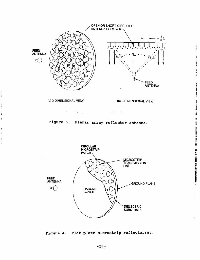
III. Description of the Microstrip Reflectarray
When many antenna elements with open or short circuited
terminations are arranged in a planar aperture and are illuminated
by a feed antenna as shown in Figure 3, these elements will re-radiate their illuminated energy into space. The total re-radiated
energy will be non-coherent in phase, even when all the elementsand their terminations are identical. This is because the fields
that propagate to the elements from the feed have different path
lengths, Sl, S2, .... SN, as shown in Figure 3(b), and thus formdifferent phases. However, if each element's phase is adjusted to
compensate for these different path lengths, the total re-radiatedfield can be made coherent and concentrated toward a specific
direction. Many different types of radiators, such as horn,
dipole, etc., can be used on the planar structure. If this planar
structure is required to be thin, then a printed-circuit type of
element needs to be employed. Several of these printed-circuit
flat plate antennas have been attempted previously without much
success. An early attempt [41used the flat plate concept as a lensrather than as a reflector. Very low efficiency (25%) was
reported. Recently, Malibu Research Center has demonstrated a flat
plate reflector [51 without showing much data on efficiency. Both
above attempts used either resonant slots or dipoles without any
phase delaying transmission lines. Only the size of the slot or
dipole is varied for phase trimming which is achieved by adding
-3-
reactance into the element's radiation impedance. This is
equivalent to saying that the phase of the dipole's surface current
is different for different dipole lengths. With properly designed
phase distribution, beam coherence can be achieved by these arrays.
This, however, will result in reduced radiation efficiency. Since,
for a particular frequency, there is only one optimum size of the
resonant structure to transmit through or reflect energy, othersizes will result in l:0w amplitude. Reference [4] printed that,
"amplitude must be sacrificed at the expense of phase change". A- [61more recent study has used equal-size dipoles with periodic
spacing so that all the dipoles have the same illumination phase as
the feed. This is the so-called frequency grating and is very
sensitive to frequency change. It is therefore used as a frequency
scanned offset-fed flat reflector antenna. Aperture efficiency of
50% has been achieved by this antenna. Due to its required offset-
fed configuration, this antenna cannot be effectively used in the
SCANSCAT application _.
The flat plate antenna proposed here uses the reflectarray N
concept where a short transmission line is attached to each
radiator for phase adjustment. The electrical lengths of these
transmission lines are made different depending on their radiators'
positions from the feed. All the radiators, however, are identical
in size and are made of thin microstrip patches. This antenna, as
shown in Figure 4, is called the microstrip reflectarray. It is
Composed of a thin (S0.02 wavelength) slab of dielectric material
having one side completely covered with a layer of thin metal
(which serves as a ground plane) and the other side etched with
many identical metallic microstrip patches. A feed antenna,
located at an optimally designed distance from the flatplate, will
effectively illuminate all the metallic patches. The size of each
patch, which can be rectangular, square, or circular, is made to
resonate at the same frequency as the feed antenna. A short
transmission line is connected to each patch at one end with the
other end of the line either open or short circuited. This
transmission line can be either a microstrip line etched on the
i
i
i
iI
i=
-4-
same side of the patches or a stripline sandwiched in an additional
layered structure behind the ground plane. The advantage of the
microstrip line is ease of fabrication with very little impact on
antenna weight, while that of the stripline is minimum interference
to the patch's radiation. When the radiation field of the feed
antenna (in transmit mode) strikes each patch, the receivedresonant field of the patch will travel through its connected
transmission line and be reflected by its open Or short circuited
termination and then re-radiate through the patch into space.
Thus, all the microstrip patches behave as re-radiators, while theshort transmission lines serve as phase delay lines. The lengths
of these transmission lines are intentionally made different for
differently located patches so that the path delay differences fromthe feed antenna can be compensated. With proper design and
calibration of these line lengths, the re-radiated fields from all
the patches can be made coherent and concentrated toward thebroadside direction. Also by re-designing the line lengths, the
main beam can be directed toward other directions. Since the
required phase changes for all the elements are between 0 ° and
360 ° , the maximum length needed for the transmission line is only
a half-wavelength. Consequently, the insertion loss associated
with these short lines will be insignificantly small. However,
this half-wavelength transmission line will work for a narrow
bandwidth (SI%) application. For a wider bandwidth, a frequency
excursion error will occur, especially for the outer elements of
the array (assuming the feed is located at the center axis of the
array). In other words, the phase will accumulate more error for
the outer elements. This accumulated phase error can be reduced by
using longer transmission lines for the center elements and/or by
using a larger f/D ratio (where f is the distance between the feed
and the patches, and D is the diameter of the reflectarray).
Since the microstrip reflectarray does not require any power
divider, its efficiency in a large array system is much higher than
a conventional array having the same aperture size. One possible
drawback of this reflectarray is that, in addition to the re-
-5-
radiated fields from the patches, there will also be scattered
field from the patches, reflected field from the ground plane
(especially at off-resonant frequencies of the patch), and
diffracted fields from edges of the flat plate. These
backscattered fields may increase the sidelobe level and possibly
distort the main beam shape. However, as long as the aperture
directivity of the flat plate is sufficiently higher (25dB or more)
than the feed directivity, the backscattered energy will be
insignificantly small. In other words, as will be demonstrated ina later section, the microstrip reflectarray will be an efficient
antenna system only if it has a large number of elements (thousands
or more) .
IV. Application to SCANSCAT
The proposed microstrip reflectarray for SCANSCAT is configured
in Figure 5 where each patch has two orthogonally connected
transmission lines with different lengths. Each one corresponds to
a different elevation beam. Although not required, this orthogonal
connection and the proper phase settings can separate the two
different elevation beams 90 ° apart in azimuth. To meet the four-
beam requirement of SCANSCAT, four feeds are needed as shown in
Figure 5. Each two with the same polarization, due to their
spatial separation, will generate the two separated transmit and
receive beams. This is because each different feed location will
form a different set of phases to illuminate the patches and, thus,
generate a different beam position. Each two feeds that have
different polarizations will generate two beams at different
elevation and azimuth angles due to the two different settings of
transmission line lengths on the microstrip patches. Because of
the elegance of this design, all four beams will have horizontal
polarization as required. These four beams are to be scanned in
azimuth by spinning mechanically at the center of the circular flat
plate. Due to the fact that the mass of the circular flat plate is
more concentrated toward the center of rotation than the previously
proposed dual-reflector design (Figure 2), the spin momentum will
i
i
|m
-6-
be much less. In addition, due to the microstrip design, the
overall antenna volume and mass will also be much less than the
dual-reflector system.
To meet the SCANSCAT's 47dBi of minimum gain requirement,
approximately 65,800 microstrip patches are needed. This hugenumber of elements does not impact the efficiency of the antenna
system since no power-dividing circuitry is needed for thereflectarray. The entire array has a diameter of 3.1 meters with
a preliminarily designed feed location of 1.5 meters from the
array. This 1.5 meters of feed separation (0.5 f/D ratio) is not
necessarily an optimum number. If the feed gets too close to the
array, the frequency excursion error will increase and thereforewill narrow the operational bandwidth. If the feed is too far away
from the array, the mechanical deployment and structure support
problems may become severe. Certainly, the feed spillover
efficiency and illumination efficiency are also determining factorsin designing the feed location. This feed location optimization
should be done together with a mechanical engineer.
V. Analysis of the Microstrip Reflectarray
Consider a planar array consisting of M x N microstrip patch
elements that is non-uniformly illuminated by a low-gain feed at rf
as shown in Figure 6. Let the desired beam direction be specified
by unit value _. Then the re-radiated field in the U direction
will be of the form
M N
m-i n-1
exp {-jk[:Fmn - r-_: + r--ran" d] + ja=) + E z + E_
(1)
-7-
where F is the feed pattern function, A is the pattern function of
the microstrip patch on the flat plate, rm is the position vector
of the mnth patch, and _m is the required transmission line phase
delay of the mnth element for beam coherence. The condition that
the beam will be coherent at desired direction Uo is
an - k[IF_ - Fzl + r_ • do] = 2n_, n = 0, i, 2 ....(2)
The feed function F is modeled by cosqo function. For the patternz
function A of the single square or rectangular microstrip patch oni
the flat plate, a simple closed form model using the dual-slot
theory [3]is employed. This simple model, which is accurate enough
for large array prediction, allows the computation time of many
thousands of array elements to be significantly reduced. The/ -
radiatlon patterns of the 0 and _ components from each slot of the
dual-slot model, as "zllustrated in Figure 7, is given as follows:
sin (k a cos_ sin@) Cos (k b sin_ sin8) cos A
e k a cos_ sin0 (k b sin_ sin0) 2 - (_/2) 2 (3)
iE sin (k a cos@ _sin0) . cos (kb sin_ sin0) sin • coso |
, = - k a cos_ sin 8 (k b sin_ sinS) 2 - (_/2) 2 _ (4) |
B
where a is half the dielectric thickness (slot width) and b is half
the patch width (slot length), and K = 2_ _E,/A o. The terms Er and
Ed in equation (i) are, respectively, the specular reflected field
from the flat ground plane and the diffracted field from the edges
of the ground plane. Both Er and Ed are calculated via the
technique of the Uniform Geometrical Theory of Diffraction [2'3].
Although E, does not give an accurate solution for the scattered
fields from the patches and the ground plane, it gives the worst
solution (maximum backscattered field is reflection). This can be
-8-
assumed because the patches are separated within a very small
distance (S0.02 wavelength) from the ground plane, and the flat
plate reflectarray can thus be treated RF wise as a perfect
conducting plane. This is especially true at off-resonant
frequencies. To accurately predict the backscattered fields from
thousands of non-uniformly illuminated microstrip patches with
unequal lengths of microstrip transmission lines will require the
development of a complex analysis technique which is beyond the
scope of the current allocated fund. The fields Er and Ed, no
matter how accurate their calculation, are insignificant to the
main beam when the array aperture gain is about 30 dB higher than
the gain of the feed antenna, which is indeed the case for
SCANSCAT. Nevertheless, these two terms are included in the
analysis so that the worst possible sidelobe level due to scattered
fields can be predicted.
The efficiency of the microstrip reflectarray is primarily
governed by the aperture illumination efficiency and feed spillover
efficiency [g]. Aperture illumination efficiency is caused by unequal
illumination of the array due to the feed pattern. The spillover
efficiency is the ratio of the amount of feed energy that
illuminates the entire array to the amount of energy that spills to
the outside of the array. The calculation of these two
efficiencies are very similar to that of a parabolic reflector. My
colleague, Dr. Vahraz Jamnejad, with his many years of reflector
experience, has assisted me in calculating these two efficiencies.
With the q factor in the feed pattern cosq8 chosen to be 3 and the
feed separation of 1.5 meters from the 3.l-meter diameter array,
the efficiency of the overall microstrip reflectarray for the
SCANSCAT is calculated as following:
-9-
Table i. Estimated microstrip reflectarrayefficiency for SCANSCAT
• !
spillover
illumination
patch loss
feed loss
91
83
95
95
termination loss 95
total 65
Because the proposed microstrip: reflectarray for SCANSCAT is an
electrically large array, the above estimated 65% antenna
efficiency is considered quite good. In addition, the illumination
and spillover efficiencies may be improved by optimally designing
a special feed instead of using the cosqe feed pattern.
A computer code based on the formulation in Equation (i) has
been written with the FORTRAN language and user friendly inputs.
For the SCANSCAT antenna, the patterns of the 36 ° and 49 ° scanned
beams are calculated. For brevity's sake, only the 49 ° scanned
beam patterns are presented here. Figure 8 gives the coordinate
system of the reflectarray geometry. The radius of the
reflectarray is 72 Ao and the patch elements are spaced 0.5 Ao
apart, with Ao being the free space wavelength. Each patch element
is 0.32 Ao x 0.32 ko square with a substrata thickness of 0.01 k o and
a dielectric constant of 2.2. The feed has a symmetrical cosqe
power pattern with q = 3 and an illumination edge taper of -9dB.
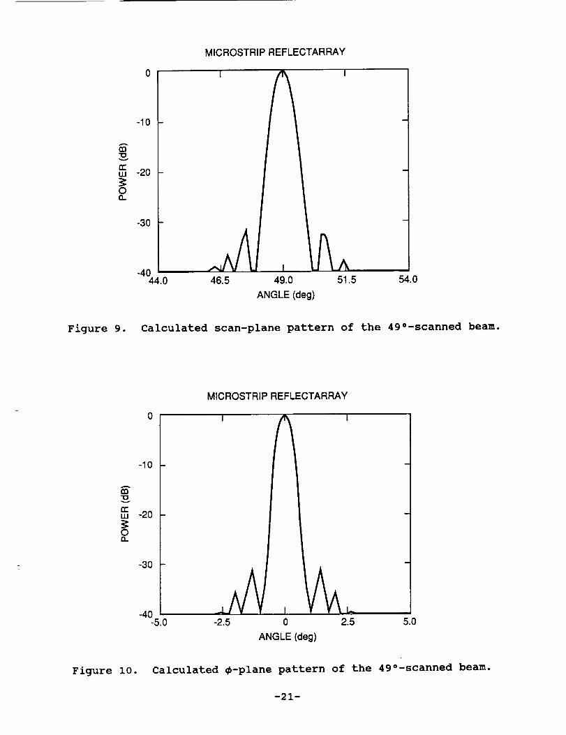
Figure 9 is the calculated far field pattern in the X-Z plane when
all the phase delay transmission lines on the patches are set for
a beam scan of 49 ° in the x-z plane. The feed is located at (XF,
YF, ZF) = (0., 0., 0.) or (x, y, z) = (0., 0., 72 ko) with an f/D
ratio of 0.5. Both the feed and the patches are polarized in the
Y-direction so that, when the z-axis of the array is pointed at
nadir and the beam is scanned in the x-z plane, a horizontally
i
i
!|
i
i
-i0-
polarized beam is achieved. This pattern shows a 3-dB beamwidth of
0.75 ° and peak sidelobe level of -32dB. The beamwidth of 0.75 ° may
be reduced down to the required 0.70 ° by a feed optimization
program. It needs to illuminate the array more uniformly to
increase the effective aperture and thus reduce the beamwidth.
Figure i0 gives the _-plane pattern (constant 8 = 49 ° plane) with
a 3-dB beamwidth of 0.64 ° and a peak sidelobe of -31dB. The
calculated directivity of this 49 ° scanned beam is 50.3dBi which,
after subtracting 65% of efficiency loss, indicates an antenna
peak gain of 48.4dBi. This is about 1.4dB above the required
minimum gain.
Figure ii gives the _-plane pattern when the feed is displaced
0.4 Ao in the +y-direction (XF, YF, ZF = 0., 0.4 ko, 0.), while all
other parameters of the array are kept the same as those for
Figures 9 and i0. The beam shows a shift of 0.34 ° in the -_
direction. With a second identical feed located at YF = -0.4 ko,
another beam with a 0.34 ° shift in the +_ direction can be formed.
Separate transmit and receive beams can thus be achieved for the
SCANSCAT. The shifted beam shown in Figure Ii has a coma lobe at
-25dB level which is still acceptable to SCANSCAT. This coma lobe
distortion is a consequence of phase errors that resulted from all
the phase delay lines with settings designed for a focal feed
rather than an off-focal feed.
To demonstrate the effect of backscattered field components --
E r and E d of Equation (i) -- Figure 12 presents the pattern for the
same antenna (diameter = 144 ko) as in Figure 9 except with the
horizontal axis expanded and with less sampling accuracy in the
pattern. This pattern does not include the effect of E, and E d and
shows no far-out sidelobes above -60dB (mainbeam peak is normalized
at 0dB). With this same antenna design, Figure 13 shows the
pattern that does have the terms E, and E d included. Many sidelobes
are near the -40dB level which is much lower than the SCANSCAT
requirement. Now, let us look at a smaller reflectarray with
diameter of i0 ko, f/D ratio of 0.5, and feed pattern q factor of
-I!-
3. The far field pattern of this antenna when scanned to 36 ° is
shown in Figure 14 where Ef and Ed terms are not included. For the
same antenna, the scan pattern with E, and Ed included is given in
Figure 15 where sidelobes of -17dB level are observed. Figures 12
through 15 have demonstrated that the microstrip reflectarray
antenna will not have serious high sidelobe probIems caused by the
backscattered fields when the aperture directivity is significantly
higher (such as 30dB) than £he feed directivity. In other words,
the microstrip reflectarray is a more effective antenna when it is
electrically large• Figure 16 plots the calculated antenna gain
(estimated loss included) versus the array aperture diameter. It
shows that, at the SCANSCAT frequency, the antenna gain drops much
faster with reduction in aperture size when the diameter is less
than one meter.
VI. Advantages and Disadvantages of the Microstrip Reflectarray
The numerous advantages of the microstrip reflectarray, in
addition to its excellent application to SCANSCAT, are separately
discussed below:
i. The reflectarray, being in the form of a microstrip antenna,
can be fabricated with a simple, low cost, and accurate
etching process. Being flat, the microstrip reflectarray will
be more cost effective than £he parabolic reflector when
manufactured. For example, the special molding process that
is generally required for fabricating a paraboloid is not
needed for a flat antenna.
• Due to the fact that no power divider is needed, the insertion
loss of thousands of microstrip patches in the reflectarray
will be the same as the insertion loss of a single patch and
thus achieve good efficiency. The efficiency is much better
than that of a conventional array with the same aperture size
and is estimated to be comparable to that of a parabolic
reflector (55-75% efficient).
=
-12-
• The main beam of the microstrip reflectarray can be fixed to
point at large angles (up to 60 ° ) from the broadside
direction, while a parabolic reflector can only have limited
scan (several beamwidths). Phase shifters can be placed in
the phase delay transmission lines for electronic beam
scanning.
• Since the antenna is a flat structure, its mass is likely to
be less than a curved parabolic reflector with equal aperture
size. It can be more easily mounted onto the surface of a
structure, such as a spacecraft's main body or a building,
with less supporting structure volume and mass when compared
to a parabolic reflector• As a possible application, this
microstrip reflectarray can be made as the world's largest
array antenna with relative ease in construction and low cost.
This can be true because a flat reflectarray, where the RF
loss is not a function of array size, can be constructed on
flat land (aperture parallel to the land) with its feed
mounted on top of a high tower. The size of the antenna is
only limited by the tower height• A feed height of I000 feet
with an f/D ratio of 0.5 will result in an array with diameter
of 2000 feet. This antenna size at i0 GHz can produce a
pencil beam of 0.0035 ° in beamwidth and 95dBi of directivity.
One major disadvantage of the microstrip reflectarray is the
narrow bandwidth of the microstrip patch. It is certainly no match
to the wide band property of the parabolic reflector (theoretically
infinite bandwidth). With conventional microstrip patch design, a
maximum of 3% bandwidth can be achieved. With special design, such
as a dual-stacked patch [91, the bandwidth can be increased close to
10%. The disadvantage of the narrow bandwidth of the microstrip
reflectarray can be overcome somewhat by utilizing multiple-
frequency operation. This is made possible for the flat
reflectarray by using a multiple-layer design as shown in Figure 17
where the larger patches serve as ground planes for many of the
smaller patches• A microstrip antenna having triple-frequency
-13-
capability with a three-layer design has been successfullydemonstrated [l°]. Other multiple-frequency designs are also
possible, such as multiple-ring patches and interlaced different-
size patches, shown in Figure 18.
VII. Conclusion
The flat plate microstrip reflectarray antenna has beenanalyzed by the array theory augmented by the Geometrical Theory of
Diffraction. Antenna performances, such as radiation pattern,
directivity, efficiency, etc., have demonstrated that a SCANSCAT
mechanically steered antenna is feasible. Its radiation efficiency
is comparable to a parabolic reflector antenna, while having manymechanical advantages over a parabolic reflector. Due to its low
RF loss characteristic, this antenna can be used in many large beam
scanning radar applications.
VIII. References
I. J. Huang, "SCANSCATAntenna Concepts," JPL Memo No. 3365-89-
039 (internal document), September 27, 1989.
2. R. G. Kouyoumjian and P. H. Pathak, "A Uniform Geometrical
Theory of Diffraction for an Edge in a Perfectly Conducting
Surface," Proc. IEEE, Vol. 62, pp. 1448-1461, Nov. 1974.
3. J. Huang, ',The Finite Ground Plane Effect on the Microstrip
REAO(5,99)FXoFY,FZ,QX, QYC WRITE(b,15)C15 FORMAT(" FEED POLARIZATION, IF X IP=I, IF Y IP=2 ")
READ(5.99)IPC.o. IF IP=I, BEAM NEEDS TO SCAN TO Y DIRECTION OR PHS_90 DEG FORC...HH POLARIZATION. SCAN TO X DIRECTION OR PHS=O OEG FOR VVC...POLARIZATION,o,,IP=2 BEA_ NEEDS TO SCAN TO X DIRECTION OR PHS=OC...DEG FOR HH POLARIZATION. SCAN TO f DIRECTION OR PHS=90 OEG
EK=EK1/2.1ALOG10(CSA2)EFFI=(I.-CSA2**(2.*EK))/EK/TAN(SAI/2.)EFF=(2.*EK+I.)*EFFI*EFF1E=S=I.-CSA2**(2.*(2.*EK+I.))EFI=EFF/EF$WRZTE(6,58)EFS,EFI.EF_FORMAT( I SPILL-OVER, ZLLUMINATION, TOTAL
IF(IGD.GT.1)GQ TO 82IF(IC.E0.2)GO TO 82IF(ABS(PHS).GT.0.O1)GO TO 82IF(ABS(THPL).LT.E.]GO TO _2ETHR=CJJEPHR=CJJRO:_Z*TAN(THPR)IF(R0.GT.RA)_O TO 83XPS=RO[F(THPL.LT.0.)XPS=-ROY_S=0.SSP=FZICOS(THPR)
CONTINUEWRZTE(6,97)ICDUNTFORMAT( I TOTAL NUMBER CF ELEMENTS= '.I5)YMT=-1000.YMP=-lO00.DO 22 I=I,IAIF(YMT.LT.OBT(I))YMT=OBT(I}IF(yMP.LT.0BP(I))¥MP=OBP(I)CONTINUEYMX=YMTIF(YMT°LT,YMP)¥MX=YMPOO 21 I=I,IAOBT(I)=0BT(I)-YMXOBP(I)=OBP(I)-YMXIFCOBT(I).LT.-_0.)OBT(I)=-60.IF(DBP(I).LT.-60.)OBP(I)=-60.CONTINUECALL BGNPLTCALL PLFORM(JLINLIN°,XOIM, YOIM)XX(1)=THLXX(Z)=THRIF(IC.EQ.2)XX(1)=PHLIF(IC.EQ.2)XX(2)=PHR
COMMDN/ODZ/CJ,PI,TPIpDPRSPS=SQRT(EPS)A=T/2°3=HL/2.CPHZ=CDS(PHZR)SPHI=S[N(PHIR)CTHI=COS(THIR)STH_=SIN(THIR)ARGI=TPI*A*CPHI*STHI*SPSARG2=TPI*B*SPflI*STHI*SPS[F(ARG1.LT.1.E-_)GO TO 11FI=SIN(ARG1 ) IARG1GO TO 12
COMMONIOO3/XPoYPpFXoF¥oFZaIPIF(ZPoEQ.1)GO TO 11SX=XP-FXSY=FZSZ=¥P-FTGO TO 12
11 SX=FZSY=YP-Fy
SZ=XP-FX12 SS=SQRT(SX*SX_SV*SY+SZ*SZ)
UXS=SXISSUYS=S¥/SSUZS=SZISSTHR=ACOS(UZS)PHR:&TAN2(UYSoUXS)IF(PHRoLT,O=)PHR=PHR+TPTEX=-COS(T_R)*COS(PNR)EY=-COS(THR)*SIN(PHR)EZ=SZN(THR)IF(IP.EQ.1)GO TO 14EXP=EZEyP=-EXEZP=-E¥GO TO 15
TS=ABS(TSZN_IF(TS.GT.I.E-5) GO TO 442COTA=-SQRT(Z°0)_FN*SZN(ANGI2.0-FN*PI*ON)[F(CDS(ANG/Z.0-FN*PI*ON}.LT.0.0) COTA=-COTAGO TO 443COTAfSORT(A)_COS(RAG)/T$IN
ON=SGN*NA=I.0÷COS(ANG-2°0*FN*PI*GN)BOTL = 2.0*SQRT(AB_(R_A))EX=CEXP(CMPLX(O.0oTPI*RtA))CALL FRNELS (C,$*BOTL)C=SQRT(PII2.0)*(O.5-C)S= S_RT(PI/2°0)*(S-G.5)FPA=TPI*R*(CMPLX(0.,2o)+4°*$QRT(ABS(TPI*R*A))*EX*CMPLX(C*S))RAG=(PI+ANG)/(2.0*FN)TSIN=SIN(RAG)TS=TSZN*TSINIF(TS.GT°I.E-5) GO TO 442CSCA:-Z.*FN*FN*COS(ANG'TPI*FN*ON)ICOS((PI÷ANG)/FN)
GO TO 443CSCA=A/TSUPPI=COM*CSCA*FPAONS=(-PI+ANG)I(2.0*FN*PI)SGN:SIGN(I.,ONS)N:IFIX(ABS(DNS}÷0.5)
ON=SGN*N
A:I.0÷CDS(ANG-2.0*FN*PItON)
BOTL = 2.O*SQRT(ABS(R*A))EX=CEXP(CMPLX(0.0,TPI*R*A))CALL FRNELS (C,S,BOTL)C=SQRT(PI/2.0)*(0.5-C)S= SQRT(PII2.0)*(S-O.5)FPA=TPI*R*(CMPLX(O.,2.)64°*SQRT(ABS(TPI*R*A))*EX*CMPLX(C-S))RAG=(PI-ANG)I(2.0*FN)TSIM=SIN(RAG)TS=TSIN*TSINIF(TS.GT.1.E-5) GO TO 542CSCA=-2.*FN*FN*COS(ANG-TPI*FN*ON)ICOS((PI-ANG)/FN)GO TO 123CSCA=A/TSUNPI=COM*CSCA*FPADPIR=UPPI-UNPIRETURNEND
@PRT-S TT.FRNELS
-37-
113929"SCAN(1) .FRNELS (0}
12 C3 C4 C5
6789
1011121314151617
181920
212223242526
2728293031
32333435363738394O41424344
45464748_9
SUBROUTINE FRNELS(C,S,XS)
THIS IS THE FRESNEL INTEGRAL SUBROUTINE WHERE THE INTEGRAL IS FROM
U=0 TO XS, THE INTEGRANO IS EXP(-J*Pi/2.*U*U),ANO THE OUTPUT ISC(XS)-J*S(XS).DIMENSION A(12),B(12),CC(12),0(12)
DATA A/1.595769140,-0.000001702,-I. S0_568_54--0-000576361,6-920691