Microstructural and mechanical characterizations of steel tubes joined by transient liquid phase bonding using an amorphous Fe–B–Si interlayer Nicolas Di Luozzo a,b,⇑ , Béatrice Doisneau b , Michel Boudard b , Marcelo Fontana a , Bibiana Arcondo a a Laboratorio de Sólidos Amorfos, INTECIN, Facultad de Ingeniería, Universidad de Buenos Aires – CONICET, Paseo Colón 850, C1063ACV Buenos Aires, Argentina b Laboratoire des Matériaux et du Génie Physique (CNRS UMR 5628), Grenoble Institute of Technology, MINATEC, Grenoble Cedex 1, France article info Article history: Available online xxxx Keywords: Transient liquid phase bonding process Amorphous foil Carbon steel Electron backscattering diffraction Mechanical properties abstract In this work the transient liquid phase bonding process was successfully used to join seamless carbon steel tubes using an amorphous Fe–B–Si foil as interlayer. The tubes were aligned with their butted surfaces in contact with the interlayer and the entire assembly was heated by means of an induction furnace under a reducing atmosphere. The temperature was raised to the process temper- ature (1300 °C) and then held for 7 min. The joining process was performed under a pressure of 5 MPa. The joined tubes microstructures were characterized by direct observations – scanning electron microscopy – and diffraction techniques – electron backscatter diffraction. Chemical analysis was per- formed by electron probe microanalysis. The joint region (JR) presents only ferrite grains - in contrast with the heat affected zone (HAZ) and the base metal (BM), whose microstructures consist of ferrite and cementite. Si content at the JR was precisely determined by chemical profiling, showing higher concentrations of Si compared with the HAZ and BM. These results are in accordance with the fact that the cementite is unable to form in Si enriched zones. Also, ferrite grains at the JR present high-angle grain boundaries with respect to the grains of the HAZ. Tensile tests show that the joined tubes failed away from the bond, at the HAZ, and reached 96% of the ultimate tensile strength of the BM, in the as-bonded condition. Microindentation hardness pro- files across the bonding zone are in agreement with the observed microstructures at the different zones of the bond region. Ó 2013 Elsevier B.V. All rights reserved. 1. Introduction In recent years, the transient liquid phase bonding (TLPB) pro- cess has been widely studied [1,2] in order to improve the charac- teristics of the joints by means of composition and microstructure homogenization along the joined pieces. TLPB process is commonly used in the aerospace industry - mainly superalloys [1], and involves three main steps, namely, liq- uefaction of the interlayer and base metal (BM) dissolution, liquid phase isothermal solidification and solute homogenization – with and without applied pressure [1,3,4]. On the other hand, is one of the technologies selected to over- come the known problems involved in threaded and coupled con- nection for oil country tubular goods (OCTG), particularly hot- rolled seamless steel tubes. TLPB of carbon hot-rolled seamless steel tubes, with Fe-based and Ni-based amorphous interlayers and under different conditions, were performed [5–7]. But only their measured mechanical properties were informed, giving no in- sight about the obtained microstructures. In a previous work [8], an extensive microstructural character- ization of TLPB of low carbon cold-drawn seamless steel tubes, using an amorphous Fe 96.2 B 3.8 (in wt%) foil as interlayer, were car- ried out under different holding times for the isothermal solidifica- tion stage and applied pressures. It was observed that increasing pressures reduced the isothermal solidification stage time. This is due to liquid ejection from the joint as well as increased contact of abutting surfaces. On the other hand, the scarce availability of amorphous Fe–B foils prevents its industrial application. In this study, TLPB was performed to join low carbon hot-rolled seamless steel tubes using as interlayer a commercial amorphous foil of the Fe–Si–B system. A thorough microstructure and mechan- ical characterization of the joint region (JR) was done and com- pared with that of the BM to evaluate the applicability of TLPB to OCTG tubular products. 0925-8388/$ - see front matter Ó 2013 Elsevier B.V. All rights reserved. http://dx.doi.org/10.1016/j.jallcom.2013.11.161 ⇑ Corresponding author at: Laboratoire des Matériaux et du Génie Physique (CNRS UMR 5628), Grenoble Institute of Technology, MINATEC, Grenoble Cedex 1, France. Tel.: +33 0456529328. E-mail address: [email protected](N. Di Luozzo). Journal of Alloys and Compounds xxx (2013) xxx–xxx Contents lists available at ScienceDirect Journal of Alloys and Compounds journal homepage: www.elsevier.com/locate/jalcom Please cite this article in press as: N. Di Luozzo et al., J. Alloys Comp. (2013), http://dx.doi.org/10.1016/j.jallcom.2013.11.161
Transcript
Journal of Alloys and Compounds xxx (2013) xxx–xxx
Contents lists available at ScienceDirect
Journal of Alloys and Compounds
journal homepage: www.elsevier .com/locate / ja lcom
Microstructural and mechanical characterizations of steel tubes joinedby transient liquid phase bonding using an amorphous Fe–B–Siinterlayer
0925-8388/$ - see front matter � 2013 Elsevier B.V. All rights reserved.http://dx.doi.org/10.1016/j.jallcom.2013.11.161
⇑ Corresponding author at: Laboratoire des Matériaux et du Génie Physique(CNRS UMR 5628), Grenoble Institute of Technology, MINATEC, Grenoble Cedex 1,France. Tel.: +33 0456529328.
Please cite this article in press as: N. Di Luozzo et al., J. Alloys Comp. (2013), http://dx.doi.org/10.1016/j.jallcom.2013.11.161
Nicolas Di Luozzo a,b,⇑, Béatrice Doisneau b, Michel Boudard b, Marcelo Fontana a, Bibiana Arcondo a
a Laboratorio de Sólidos Amorfos, INTECIN, Facultad de Ingeniería, Universidad de Buenos Aires – CONICET, Paseo Colón 850, C1063ACV Buenos Aires, Argentinab Laboratoire des Matériaux et du Génie Physique (CNRS UMR 5628), Grenoble Institute of Technology, MINATEC, Grenoble Cedex 1, France
In this work the transient liquid phase bonding process was successfully used to join seamlesscarbon steel tubes using an amorphous Fe–B–Si foil as interlayer. The tubes were aligned with theirbutted surfaces in contact with the interlayer and the entire assembly was heated by means of aninduction furnace under a reducing atmosphere. The temperature was raised to the process temper-ature (�1300 �C) and then held for 7 min. The joining process was performed under a pressure of5 MPa.
The joined tubes microstructures were characterized by direct observations – scanning electronmicroscopy – and diffraction techniques – electron backscatter diffraction. Chemical analysis was per-formed by electron probe microanalysis. The joint region (JR) presents only ferrite grains - in contrastwith the heat affected zone (HAZ) and the base metal (BM), whose microstructures consist of ferriteand cementite. Si content at the JR was precisely determined by chemical profiling, showing higherconcentrations of Si compared with the HAZ and BM. These results are in accordance with the factthat the cementite is unable to form in Si enriched zones. Also, ferrite grains at the JR presenthigh-angle grain boundaries with respect to the grains of the HAZ.
Tensile tests show that the joined tubes failed away from the bond, at the HAZ, and reached 96% ofthe ultimate tensile strength of the BM, in the as-bonded condition. Microindentation hardness pro-files across the bonding zone are in agreement with the observed microstructures at the differentzones of the bond region.
� 2013 Elsevier B.V. All rights reserved.
1. Introduction
In recent years, the transient liquid phase bonding (TLPB) pro-cess has been widely studied [1,2] in order to improve the charac-teristics of the joints by means of composition and microstructurehomogenization along the joined pieces.
TLPB process is commonly used in the aerospace industry -mainly superalloys [1], and involves three main steps, namely, liq-uefaction of the interlayer and base metal (BM) dissolution, liquidphase isothermal solidification and solute homogenization – withand without applied pressure [1,3,4].
On the other hand, is one of the technologies selected to over-come the known problems involved in threaded and coupled con-nection for oil country tubular goods (OCTG), particularly hot-rolled seamless steel tubes. TLPB of carbon hot-rolled seamless
steel tubes, with Fe-based and Ni-based amorphous interlayersand under different conditions, were performed [5–7]. But onlytheir measured mechanical properties were informed, giving no in-sight about the obtained microstructures.
In a previous work [8], an extensive microstructural character-ization of TLPB of low carbon cold-drawn seamless steel tubes,using an amorphous Fe96.2B3.8 (in wt%) foil as interlayer, were car-ried out under different holding times for the isothermal solidifica-tion stage and applied pressures. It was observed that increasingpressures reduced the isothermal solidification stage time. This isdue to liquid ejection from the joint as well as increased contactof abutting surfaces. On the other hand, the scarce availability ofamorphous Fe–B foils prevents its industrial application.
In this study, TLPB was performed to join low carbon hot-rolledseamless steel tubes using as interlayer a commercial amorphousfoil of the Fe–Si–B system. A thorough microstructure and mechan-ical characterization of the joint region (JR) was done and com-pared with that of the BM to evaluate the applicability of TLPB toOCTG tubular products.
2 N. Di Luozzo et al. / Journal of Alloys and Compounds xxx (2013) xxx–xxx
2. Experimental
2.1. Transient liquid phase bonding process
The materials used in this study are hot-rolled carbon seamless steel tubes EN10297-1 Grade E235, as BM, and amorphous METGLAS� SA1 foil, as interlayer. Theirchemical compositions are listed in Table 1. The steel tubes have an outside diam-eter of 73 mm and a wall thickness of 9.5 mm. The interlayer has a thickness of25 lm.
The tubes are aligned with their butted surfaces in contact with the interlayer.The butted surfaces had a roughness average (Ra) of 10.8 lm on an evaluationlength of 7.5 mm with a cut-off length of 2.5 mm. The joint was placed into the coilof an induction furnace under a controlled reducing (10% H2 + 90% Ar) atmosphere.The temperature was measured at the joint on the outer surface of the tube bymeans of infrared thermometry, at a sensing wavelength of 1600 nm. It was raisedto the process temperature TP (�1300 �C), held constant for 7 min, and then cooledin still air to room temperature. A uniaxial pressure of 5 MPa was applied during thebonding process.
2.2. Microstructure characterization
The samples for the microstructural characterization were cut perpendicularlyto the joint, that is, along the rolling direction of the tubes.
Electron backscatter diffraction (EBSD) was used to obtain inverse pole figure(IPF) maps. Measurements were done in Zeiss Ultra 55 field-emission gun-scanningelectron microscope (FEG-SEM), equipped with an EBSD detector EDAX DigiView III.The data was post-processed by means of EDAX OIM Analysis software. Step sizes of1 and 2 lm were used for scanning, with an acceleration voltage of 20 kV.
Microstructure characterization was carried out with FEI Quanta 250 FEG-SEM,using an acceleration voltage of 15 kV.
Chemical analysis was performed by electron probe microanalysis (EPMA) withCAMECA SX50.
The samples preparation was carried out using mechanical polishing. It wasperformed according to the following procedures: after surface grinding, specimenswere polished with diamond suspension of 6 and 1 lm. The final polishing varies ineach analysis: 0.05 lm colloidal silica suspension for EBSD, 0.3 lm alumina suspen-sion followed by etching with 2% Nital solution for 30 s for FEG-SEM, and no finalpolishing nor etching for EPMA.
2.3. Mechanical properties characterization
The mechanical properties of the JR and the BM were evaluated by tensile andhardness tests.
Table 1Chemical composition for E235 steel and SA1 interlayer (in wt%).
Fig. 1. (a) Microstructure of the BM: FEG-SEM micrograph showing ferrite/pearlite bandrandomly oriented assembly of grains (blue). (For interpretation of the references to co
Please cite this article in press as: N. Di Luozzo et al., J. Alloys Comp. (2013), h
The tensile samples were cut both from the joined tubes and a tube in the as-received condition in accordance to ASTM E8 M (5 mm thickness, 120 mm gaugelength and 13 mm gauge width). The tensile tests were performed at a strain rateof 8 mm/min.
Microindentation hardness profiles across the bonding zone were carried outusing a 200 gf load at the JR and a 1000 gf load at the heat affected zone (HAZ)and BM.
3. Results and discussion
3.1. Microstructural characterization
Microstructure of the BM and the HAZThe BM contained ferrite and pearlite with a prominent banded
structure as shown in Fig. 1(a). From EBSD analysis of the micro-structure we obtained:
� An average grain diameter of 19 lm.� A misorientation angle distribution plot (Fig. 1(b)) close to a
randomly oriented assembly of grains, with a small shifttowards lower misorientations.� From grain boundary character distribution analysis – where
boundaries with angles h 6 15� are classified as low-angle grainboundaries (LAGBs) whereas boundaries with h > 15� aredenoted as high-angle grain boundaries (HAGB) – we obtainedthat HAGB fraction (69.7%) is much larger than LAGB fraction(15.6%) and coincident site lattice (CSL) (14.7%).
From above it can be concluded that the BM microstructure isalmost fully recrystallized [9]. This is intrinsic of hot-rolling pro-cess, which has a phase transformation after plastic deformation.The texture generated during hot-rolling is mostly destroyed bythe subsequent phase transformation from austenite to ferrite.
The HAZ also contained ferrite and pearlite, but the bandedstructure was removed (Fig. 2(a)). From EBSD analysis of themicrostructure we obtained:
� An average grain diameter of 47 lm.� A misorientation angle distribution plot (Fig. 2(b)) which shifts
markedly towards lower misorientations.� From grain boundary character distribution analysis we
obtained that LAGB fraction clearly increased (40.4%), at theexpense of HAGB (50.0%) and CSL (9.6%).
We can conclude that HAZ meets all requirements of a recrys-tallized microstructure that suffered a grain growth process [10].
s – nital etched (b) Misorientation angle distribution plots of the BM (red) and for alour in this figure legend, the reader is referred to the web version of this article.)
Fig. 2. (a) Microstructure of the HAZ: Normal direction (ND)-projected IPF map –black lines denote HAGB and red lines denote LAGB. The rolling direction (RD) and thetransverse direction (TD) are indicated on the figure (b) Grain size distribution plots of the HAZ (red) and for a randomly oriented assembly of grains (blue). (For interpretationof the references to colour in this figure legend, the reader is referred to the web version of this article.)
Fig. 3. (a) FEG-SEM micrograph of the joint – secondary electrons. The JR and HAZ are indicated on the figure (b) Concentration profile (by EPMA) of Si and B as indicated in(a) – in yellow. (For interpretation of the references to colour in this figure legend, the reader is referred to the web version of this article.)
N. Di Luozzo et al. / Journal of Alloys and Compounds xxx (2013) xxx–xxx 3
Microstructure of the JRThe completion of the solidification process was achieved in the
entire JR – that is, the zone in which the microstructure was af-fected by the different stages of the TLPB process, but does not cor-respond to the microstructure of the HAZ. Its microstructureconsist only of ferrite grains, having a width of �70 lm, as shownin Fig. 3(a).
In this region, high Si concentrations are encountered. This ex-plains the absence of cementite, since Si prevents its formation[11]. With respect with B concentration, it has an almost constantprofile, having diffused well into the HAZ (Fig. 3(b)).
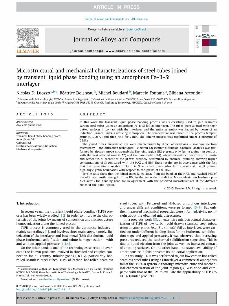
The interface between the HAZ and the JR, is characterizedmostly by grain boundaries, particularly HAGB (Fig. 4). A similarsituation was reported in TLPB of commercially pure Ni (as BM)and Ni–Cr–Fe–B–Si amorphous foil (as interlayer) [12], where bothborides and grain boundaries acts as an interface between the pre-
Please cite this article in press as: N. Di Luozzo et al., J. Alloys Comp. (2013), h
vious liquid phase and the HAZ, that is, a non-epitaxial solidifica-tion was observed.
In addition with the differences in microstructure, HAGB be-tween the JR and the HAZ are delimiting most of the extent ofthe dissolution stage, namely, the transient liquid phase zone,and are indicating that the grains at the JR were able to solidifynon-epitaxially from those of the HAZ.
It is worth noting that the fact that the JR is almost three timeswider compared with the interlayer is connected with the dissolu-tion of the BM [3], just before isothermal solidification. Similarobservations can be found in [12]. During this stage, B and Si fromthe interlayer - now liquid - begin to diffuse into the BM resultingin an impoverishment of these elements at the transient liquidphase. On the other hand, B and Si act as melting point depressantsfor the steel, and each volume of steel whose melting point reachesTP, is melted, widening the liquid gap. The above mentioned stage
Fig. 4. ND-projected IPF map from the JR. In the map, black lines denote HAGB and red lines denote LAGB. The JR and HAZ are indicated on the figure. The white dotted linesare a guide to the eye of the extension of the JR. (For interpretation of the references to colour in this figure legend, the reader is referred to the web version of this article.)
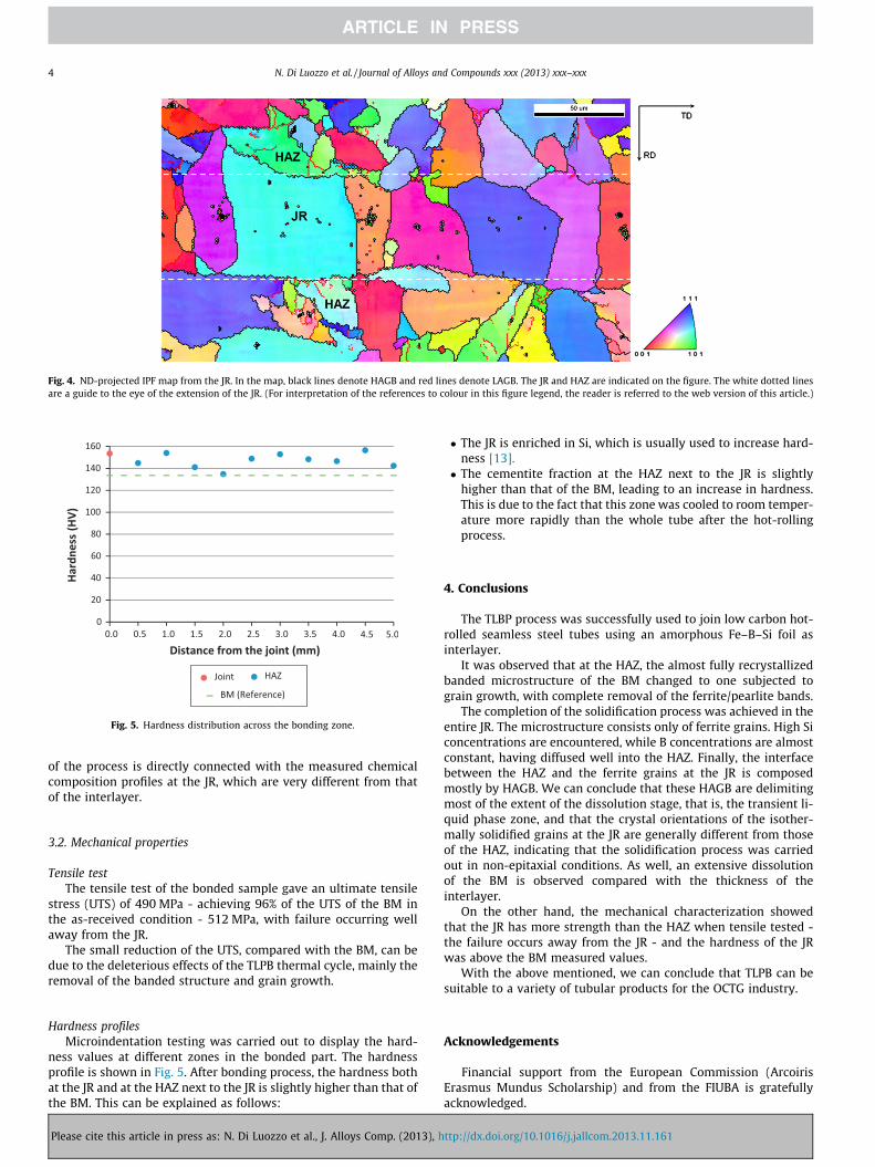
Fig. 5. Hardness distribution across the bonding zone.
4 N. Di Luozzo et al. / Journal of Alloys and Compounds xxx (2013) xxx–xxx
of the process is directly connected with the measured chemicalcomposition profiles at the JR, which are very different from thatof the interlayer.
3.2. Mechanical properties
Tensile testThe tensile test of the bonded sample gave an ultimate tensile
stress (UTS) of 490 MPa - achieving 96% of the UTS of the BM inthe as-received condition - 512 MPa, with failure occurring wellaway from the JR.
The small reduction of the UTS, compared with the BM, can bedue to the deleterious effects of the TLPB thermal cycle, mainly theremoval of the banded structure and grain growth.
Hardness profilesMicroindentation testing was carried out to display the hard-
ness values at different zones in the bonded part. The hardnessprofile is shown in Fig. 5. After bonding process, the hardness bothat the JR and at the HAZ next to the JR is slightly higher than that ofthe BM. This can be explained as follows:
Please cite this article in press as: N. Di Luozzo et al., J. Alloys Comp. (2013), h
� The JR is enriched in Si, which is usually used to increase hard-ness [13].� The cementite fraction at the HAZ next to the JR is slightly
higher than that of the BM, leading to an increase in hardness.This is due to the fact that this zone was cooled to room temper-ature more rapidly than the whole tube after the hot-rollingprocess.
4. Conclusions
The TLBP process was successfully used to join low carbon hot-rolled seamless steel tubes using an amorphous Fe–B–Si foil asinterlayer.
It was observed that at the HAZ, the almost fully recrystallizedbanded microstructure of the BM changed to one subjected tograin growth, with complete removal of the ferrite/pearlite bands.
The completion of the solidification process was achieved in theentire JR. The microstructure consists only of ferrite grains. High Siconcentrations are encountered, while B concentrations are almostconstant, having diffused well into the HAZ. Finally, the interfacebetween the HAZ and the ferrite grains at the JR is composedmostly by HAGB. We can conclude that these HAGB are delimitingmost of the extent of the dissolution stage, that is, the transient li-quid phase zone, and that the crystal orientations of the isother-mally solidified grains at the JR are generally different from thoseof the HAZ, indicating that the solidification process was carriedout in non-epitaxial conditions. As well, an extensive dissolutionof the BM is observed compared with the thickness of theinterlayer.
On the other hand, the mechanical characterization showedthat the JR has more strength than the HAZ when tensile tested -the failure occurs away from the JR - and the hardness of the JRwas above the BM measured values.
With the above mentioned, we can conclude that TLPB can besuitable to a variety of tubular products for the OCTG industry.
Acknowledgements
Financial support from the European Commission (ArcoirisErasmus Mundus Scholarship) and from the FIUBA is gratefullyacknowledged.
dx.doi.org/10.1179/136217104225021724.[5] S. Kishi, T. Maenosono, M. Sato, US Patent 5875954, 1999.[6] Y. Hamada, Y. Fukada, M. Ueda, Y. Komizo, US Patent 6059175, 2000.[7] T. Shimizu, H. Horio, K. Kito, S. Inagaki, R. Yamada, US Patent 6592154 B2,
2003.
Please cite this article in press as: N. Di Luozzo et al., J. Alloys Comp. (2013), h
[8] N. Di Luozzo, M. Fontana, B. Arcondo, J. Mater. Sci. 43 (2008) 4938–4944,http://dx.doi.org/10.1007/s10853-008-2720-0.
[9] R. Saha, R.K. Ray, Mater. Sci. Eng. A 527 (2010) 1882–1890, http://dx.doi.org/10.1016/j.msea.2009.11.019.
[10] F.J. Humphreys, M. Hatherly, Recrystallization and Related AnnealingPhenomena, Elsevier, Amsterdam, 2004.
[11] H. Bhadeshia, R. Honeycombe, Steels: Microstructure and Properties, Elsevier,Amsterdam, 2006.
[12] J. Ruiz-Vargas, N. Siredey-Schwaller, N. Gey, P. Bocher, A. Hazotte, J. Mater.Process. Technol. 213 (2013) 20–29, http://dx.doi.org/10.1016/j.jmatprotec.2012.07.016.
[13] B.L. Bramfitt, A.O. Benscoter, Metallographer’s Guide: Practices and Proceduresfor Irons and Steels, ASM International, Novelty, 2002.