MICROSTRUCTURAL AND MECHANICAL PROPERTY CHARACTERIZATION OF AGED INCONEL ALLOY 625LCF. Charles R. Conder and Gaylord D. Smith Into Alloys International, Inc. 3200 Riverside Drive Huntington, WV 25705 and John F. Radavich Micro-Met Laboratories, Inc. 209 North Street West Lafayette, IN 47906 ABSTRACT Industrial and aerospace applications for INCONEL" alloy 625LCF" sometimes require thermal exposure in the temperature range of 593OC to 650°C for extended periods of time. The alloy has the potential to precipitate both y" and M,,C, carbides in this temperature regime with concomitant changes in mechanical properties. This paper correlates observedmicrostructural changes as a function of time and temperature with selected properties for the alloy. Microstructural features as defined by microscopy, SEM and X-ray identification of extracted phases were utilized to characterize the microstructure after exposure at 593OC and 650°C for times to 7500 hrs (11 months). The same material was evaluated for its room and high temperature tensile properties. Observations from this study were compared to historical reports of microstructure and properties. @ INCONEL and 625LCF are registered trademarks of the Into group of companies. Superalloys 718,625, 706 and Various Derivatives Edited by E.A. Loria The Minerals, Metals &Materials Society, 1997 447
Transcript
MICROSTRUCTURAL AND MECHANICAL PROPERTY CHARACTERIZATION OF AGED INCONEL ALLOY 625LCF.
Charles R. Conder and Gaylord D. Smith Into Alloys International, Inc.
3200 Riverside Drive Huntington, WV 25705
and
John F. Radavich Micro-Met Laboratories, Inc.
209 North Street West Lafayette, IN 47906
ABSTRACT
Industrial and aerospace applications for INCONEL" alloy 625LCF" sometimes require thermal exposure in the temperature range of 593OC to 650°C for extended periods of time. The alloy has the potential to precipitate both y" and M,,C, carbides in this temperature regime with concomitant changes in mechanical properties. This paper correlates observedmicrostructural changes as a function of time and temperature with selected properties for the alloy. Microstructural features as defined by microscopy, SEM and X-ray identification of extracted phases were utilized to characterize the microstructure after exposure at 593OC and 650°C for times to 7500 hrs (11 months). The same material was evaluated for its room and high temperature tensile properties. Observations from this study were compared to historical reports of microstructure and properties.
@ INCONEL and 625LCF are registered trademarks of the Into group of companies.
Superalloys 718,625, 706 and Various Derivatives Edited by E.A. Loria
The Minerals, Metals &Materials Society, 1997
447
Introduction
Since its introduction in 1989, INCONEL alloy 625LCF has grown in industrial acceptance. Applications are similar to those of conventional alloy 625 which is typically used in exhaust systems, thrust reversers, bleed air ducting, combustors, transition ducts and engine components.(l) Because of its optimized chemistry and improved fatigue resistance, alloy 625LCF is finding increased acceptance in these applications. Due to its finer grain size and tighter composition compared with conventional alloy 625, it exhibits excellent mechanical and fatigue properties.
In recent years, the increased use of alloy 625LCF in the temperature range of 593OC and 650°C for aerospace and other industrial applications has required more attention to microstructural and mechanical properties with extended exposures within this temperature regime. This is crucial in that alloy 625LCF, similar to alloy 625, has the potential to precipitate %,C,, M,C, Y" and y' which can influence various mechanical properties such as impact and tensile strength and fatigue resistance. Also, extended exposure times could coalesce these precipitates, thereby further altering material performance.
Extensive characterization of conventional alloy 625 in this temperature regime has been done.'2' But there has been limited work done on characterizing the microstructural and mechanical stability of alloy 625LCF. Figures 1 and 2 are historical time- temperature-transformation (TTT) diagrams for solution treated alloy 625.(3,4) The TTT diagrams differ with respect to the precipitation of M,,C, and M,C. This difference could be related to composition and grain size. The silicon and carbon content appears to have an effect on the quantity and type of carbides that are precipitated15'.
Earlier studies of alloy 625 reported an abundant amount of 11 in the matrix and 6 (Ni,Cb) in the grain boundaries with
zxtended exposure at 650°C.'2' Also, it was determined that a-Cr formed at the grain boundaries and that it tended to increase with time.
It is the objective of this work to characterize the microstructural and mechanical relationship for extended times at 593OC and 650°C for alloy 625LCF.
Development of INCONEL alloy 625LCF
Alloy 625 sheet and strip is often manufactured using electric arc furnace melting, argon-oxygen-decarburization (AOD) refining followed by electroslag remelting (ESR). The cold rolled product is given a final hydrogen anneal at 1175OC which results in a product with a 0.2% yield strength of 330 to 380 MPa and an ASTM grain size number of 5 or finer. The extracted total residue contents (precipitates in the as-annealed condition) are shown in Table I. To reduce inclusion content, a VIM + ESR heat of alloy 625 was produced and processed with restricted carbon, nitrogen and silicon using the same strip manufacturing procedure employed for the AOD + ESR heatc6'.
Table I: Precipitated Phqses in Annealed INCONEL alloy 625LCF
Melt Method Total Residue (Nb,Ti) (C,N) TiN (weight %) (weight %) (weight %)
AOD + ESR 0.38 0.30 0.08
VIM + ESR 0.09 0.06 0.03
In contrast to AOD + ESR produced alloy 625 it is clear that a vacuum induction melted (VIM) plus ESR of higher purity has a lower total residue content, particularly of (Nb,Ti) (C,N). This higher purity results in higher fatigue properties. See Figure 3.
449
103 104 105
Log Cyc I es to Fa i I ure
Figure 3: Stress Controlled Tension-Tension Fatigue Properties at 540°C for Two Heats of Differing Composition and Method of Manufacture. (Ref. 6)
Procedure
25.4mm thick alloy 625LCF plate and 1.02mm thick sheet, vacuum induction melted (VIM) plus electroslag remelted (ESR), were selected for the characterization study. Their compositions, as well as the nominal composition for alloy 625, are listed in Table II. The plate was annealed in air at 10IO°C / 1.0 hr. The sheet was continuous annealed in hydrogen at 1024OC.
To characterize the effect of exposure at 593OC and 650°C, specimens were aged at each of these temperatures for various times up to 7500 hrs (11 months). Each condition was tested for room and high temperature tensile properties (ASTM E-8). The microstructures were analyzed via use of X-ray diffraction (XRD) of extracted phases and scanning electron microscopy (SEM) of the microstructure.
Themetallographic samples werepreparedbyelectro-polishing for 20 seconds at 25 volts in a 20% H,SO,-methanol solution after grinding them to a 6p.m diamond finish. The samples were etched by electro-etching for 8 seconds in a CrO,-H,PO,-H,SO, solution at 5 volts. This etching procedure will put y',y", and 6 in relief to provide optimum contrast on the SEM.
The extractions were performed using 10% HCl-methanol at 5 volts for 1 hr with the residue ultrasonically removed in alcohol every 10 minutes. Part of the residue was applied to a carbon stub for SEM and EDS evaluation while the bulk of the residue was used for XRD studies to identify the phases. Because certain phases are not extracted by the etchant, the partially extracted
sample was analyzed using SEM to determine phases remaining which were not removed during the extraction procedure.
Results
Mechanical property test results for alloy 625LCF after short term exposures for the sheet product and long term exposures for the plate product are listed in Tables III thru VI. Selected SEM/EDX photomicrographs illustrating the morphology of the various phases are shown in Figures 4 thru 9.
Mechanical Properties
The results listed in Table III are for short term exposures on alloy 625LCF sheet. The results show an increase in yield strength after short term exposures of approximately 24 hrs at 593OC and 16 hrs at 65OOC.
The room and high temperature tensile properties of alloy 625LCF plate with extended exposure times at 593OC and 65O'C reveal a reduction in ductility. See Tables IV and V. But the ductility remains above 20%. The yield and tensile strength results show a reduction after 5000 hrs (7 months) at 650°C and a steady increase up to 7500 hrs (11 months) exposures at 593OC. When long-term aging at 593OC and 650°C occurs, the original properties can be restored by annealing at 954OC/l hr/AC. See Table VI.
451
Table III - Room Temperature Tensile Properties of Alloy 625LCF Sheet, After Aging a< 593°C and 650°C for-Various Exposure Times
AS Annealed (1024OC in H,) 1 525.4 941.2 46.5
1 544.0 951.5 46.4 I I I
I 2 I 559.2 1 970.8 1 45.6
593OC
4 559.9 969.4 45.1
8
Aging Twperatwa
Yield Tensi& Strength Strength Elongation
tMPa1 @IPal (%I I
16 568.1 970.8 45.5
24 583.3 977.7 44.8
1 559.2 983.2 45.8
2 542.6 943.9 45.9
4 573.0 984.6 45.2
650°C 8 591.6 985.3 42.9
16 679.2 1,050.8 39.6
24 756.4 1.123.9 37.6
Table IV - Room Temperature Tensile Properties of Alloy 625LCF Plate, After Aging at 593'C and 65O'C for Various Times.
Aging Yield Tensile Exposure Temperature Strength Strength Eltingation
Time fMPaf WPaf j 6%)
As Annealed (lOIO°C in Air) 484.7 943.9 46.0 2500 hrs 890.1 1,257.0 29.0 5000 hrs 935.0
Table V - High Temperature Tensile Properties of Alloy 625LCF Plate, After Aging at 593'C and 650°C for Various Times. (The Test Temperature was the Aging Temperature).
Yield Tensile Exposure Age k Test Strength Strength
Time Temperature IMPa) fMPa1 f%)
2500 hrs 734.3 1,050.l 29.5
5000 hrs 593OC 839.1 1,143.2 26.9
7500 hrs 906.7 1,183.2 22.2
2500 hrs 808.8 1,065.3 32.3
5000 hrs 650°C 809.5 1,080.4 24.7
7500 hrs 766.0 1,033.6 18.1
Note: Average of Two Specimens
Table VI - Room Temperature Tensile Properties of Alloy 625LCF Plate, After Aging at 593'C and 650°C for Various Times followed by an Anneal at 954°C.
XRD and SEM evaluations revealed finely dispersed y" and y' within the matrix after 24 hrs at 650°C and 7 months at 593OC. Extended exposure times ultimately transformed a portion of these finely dispersed precipitates to 6. This transformation was more pronounced at the grain boundaries. See Figures 4 - 7.
453
Figure 4 - SEM photomicrograph of alloy 625LCF after an exposure at 593OC for 5000 hrs (7 months). This illustrates the beginning formation of carbide plates and small quantity of y" and y'. Magnification: 10,000X
Figure 5 - SEM photomicrograph of alloy 625LCF after exposure at . - __ 593OC for 7500 hrs (11 months). This shows a larger amount or y" as well as some M,C and MC carbides. Magnification: 10,000X
454
Figure 6 - SXM photomicrograph of alloy 625LCF after an exposure at 650°C for 2500 hrs (4 months). There are large amounts of y" similar to that of 593OC for 7500 hrs (11 months). Magnification: 10,000X
Figure 7 - SEM photomicrograph of alloy 625LCF after exposure at 650°C for 5000 hrs (7 months). There is some coarsening of carbides and a larger quantity of 8 platelets forming. Magnification: 10,000X
455
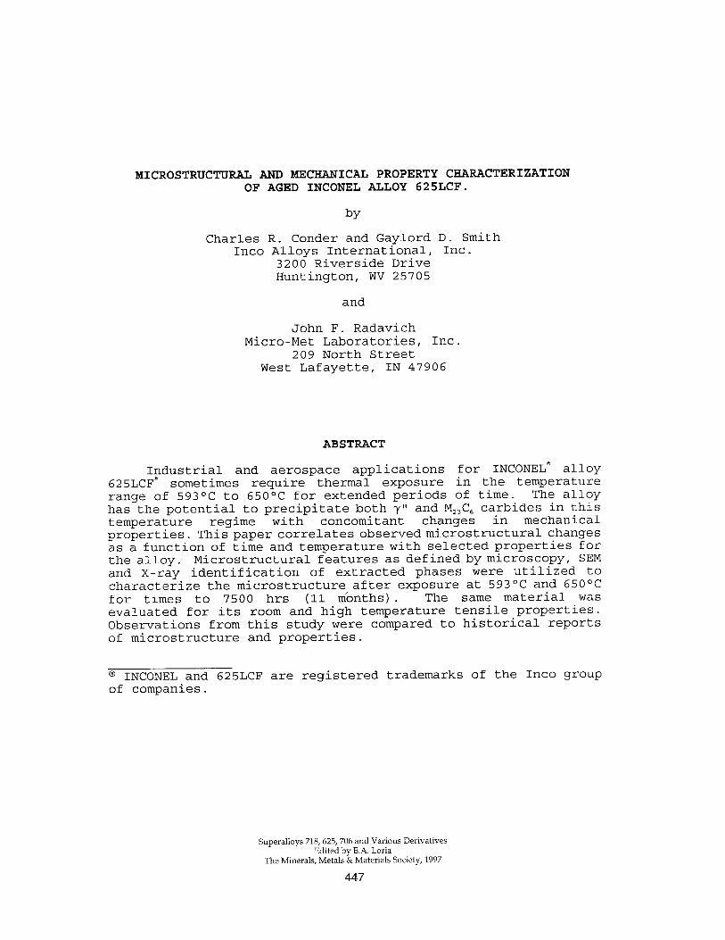
As in the case of alloy 625 it was found that alloy 625LCF precipitated cr-Cr, Figures 8a and 8b. a-Cr was detected after approximately 2500 hrs (4 months) at 650°C and 7500 hrs (11 months) at 593OC. The cu-Cr and 6 most likely contribute to the loss in ductility after extended times at 593OC and 650°C.
Figure a - SEM photomicrograph of alloy 625LCF after an exposure at 650°C for 7500 hrs (llmonths). a) a-Cr is associated with the grain boundary b) A higher magnification of the grain boundary. Magnification: a) 3,000X b) 10,000X
456
In contrast to results of previous studies of alloy 625, the XRD did not detect any M,,C, carbide in alloy 625LCF. As mentioned previously, the most likely reason for this would be the low carbon and silicon content of alloy 625LCF. M,C and MC carbide precipitates were detected. It is considered that these carbides are introduced during the anneal, Figure 9.
Figure 9 - SEM photomicrograph of As-Annealed alloy 625LCF. There are finely dispersed M,C and MC carbides introduced by the 1010°C anneal. .
Magnification: 10,000X
Understanding of the long term stability of alloy 625LCF would be enhanced with an extension of this study to 820°C with additional characterization of phase growth kinetics and phase volume percentage as a function of time and temperature.
Conclusions
1) XRD analysis of alloy 625LCF at 593OC and 650°C! after extended exposures up to 7500 hrs (11 months) did not detect M,,C, in the microstructure.
2) Both extractions and SEM evaluations confirm that extended exposure for 7500 hrs (llmonths) at 593OC and 2500 hrs (4 months) at 650°C precipitated a-Cr at the grain boundaries.
3) XRD and SEM evaluations revealed finely dispersed intragranular y" and y' after 24 hrs at 650°C and 5000 hrs (7 months) at 593OC. Longer exposure times exhibited larger quantities of these phases with a portion ultimately transforming to 6 phase. The tendency for this transformation was more pronounced at the grain boundaries.
457
4) M,C and MC carbides are introduced during the anneal of alloy 625LCF.
5) Extended exposure on room temperature yield strength at 593OC and 650°C shows an increase in yield strength at 593OC for exposures up to 7500 hrs (llmonths), but decreases after 5000 hrs (7 months) at 65OOC.
6) After extended times at 593OC and 650°C there is a reduction in tensile elongation. But it remains greater than 20%.
7) An anneal of 954OC/l hr/AC after all exposures at 593OC and 650°C restores alloy 625LCF original properties by re-solutioning cr-Cr , 6 and y".
References
1. G. D. Smith and D. H. Yates, l'Optimization of the Fatigue Properties of INCONEL alloy 625, II Proceedings of Superalloys, 718, 625 and Various Derivatives, June, 1991, pp. 509-517, The Minerals, Metals & Materials Society, Warrendale, Pennsylvania.
2. J. F. Radavich and A. Fort, in Alloy 625 at
"Effects of Long-Time Exposure 1200°F,14000F and 1600°F,11 Proceedings of
Superalloys 718, 625, 706 and Various Derivatives, June 1994 , pp. 635-647, The Minerals, Metals & Materials Society, Warrendale, Pennsylvania.
3. E. Schnabel, H. J. Schiiller, P. Schwaab, "The Precipitation and Recrystallization Behavior of the Nickel-Base-Alloy INCONEL alloy 625," Prakt. Metallographie, Vol. 8, 1971, PP. 521-527.
4. J. R. Crum, M. E. Adkins and W. G. Lipscomb, "Performance of High Nickel Alloys in Intermediate Temperature Refinery and Petrochemical Environments," Paper No. 208, Corrosion 86, The National Association of Corrosion Engineers, Houston, Texas, 1986.
5. Y. S. Wang, X. M. Guan, H. Q. Ye, J. Bi, A. S. Xu, "Effect of Silicon on Grain boundary Carbide Precipitation and Properties of a Cobalt-Free Wrought Nickel-Base Superalloy," Superalloys 1980, pp. 63-72, American Society for Metals, Metal Park, Ohio.
6. G. D. Smith, J. R. Crum and R. A. Smith, "Alloy Optimization for Enhanced Flexible Coupling Performance," Paper No. 960578, February, 1996, Detroit, Michigan, SAE International, Warrendale, Pennsylvania.