La Metallurgia Italiana - n. 2 2016 13 INTRODUCTION Electrolytic Tough Pitch (ETP) Copper and its alloys have excellent properties, such as good ductility, corrosion resistance, electrical conductivity, thermal conductivity and due to these reasons it is most widely used in industrial applications [1]. In conventional fusion welding, a high heat is required for good welding of ETP copper. The high heat input results coarsening of grain size wide heat affected zone (HAZ), distortion and low joint strength. A new solid state joining technique, of Friction Stir Welding (FSW) could be selected to overcome these problems. Friction Stir Welding (FSW), invented by The Welding Institute of United Kingdom in 1991, is an energy efficient, environmentally friendly and versatile joining technique. FSW does not require any filler material and shielding gas. It involves low energy input, short welding time and low welding temperature [2]. During FSW, the weld materials undergo a severe plastic deformation and dynamic recrystallization in weld nugget (WN). The temperature in FSW is lower than the melting point of the weld materials. Good qualities of welds are obtained with low distortion and satisfactory weld joint efficiency due to lower heat input than that of fusion welding. There are many industrial applications of FSW, such as production of ship panels, Air frames, fuel tanks and thin alloy skins in the aerospace. Sheet body work and engine support frames for the automotive industry etc., [2]. Many researchers have reported on FSW of aluminium and its alloys, whereas only few research reports are available for copper and its alloys [3]. Previous studies reported that higher rotational speeds with low travel speed result defect free copper weld joints. Lee et al [4] found that defect free weld in a 4 mm. The welding tool was titled by an angle of 3 degree with the vertical axis. The tool was rotated in the clockwise direction. The heat generated during FSW of copper resulted in recrystallized fine grains in the weld nugget. Xie et al.[5] welded 5mm thick copper plate using a tool with cylindrical threaded pin. A significant dependence of the recrystallized grain size and microhardness on the rotating speed was evidenced. In particular in the upper range of the considered rotational speeds (600-800 rpm) a decrease in the microhardness with respect to the BM was found, despite the finer microstructure observed. Sakthivel et al [7] observed defect Microstructure and mechanical behaviour of friction stir welded etp copper N. Srirangarajalu, A. Rajadurai Copper and its alloys are difficult to weld by conventional welding process, due to high thermal conductivity and high melting point, Friction Stir Welding (FSW) is used to overcome the problems encountered in conventional welding process. This experimental study was conducted to analyse the joining behaviour of 6mm thick Electrolytic Tough Pitch (ETP) cold rolled copper plate. The role of tool rotational speed, travel speed and tool pin profile, on the weld quality, tensile, bend behaviour, hardness, macrostructure, microstructure and fracture behaviour were investigated. Defect free weld was obtained at tool rotational speeds ranging between1300-1600 rpm and travel speeds ranging between 30-45mm/min. Tensile strength of the welded specimen was found to be 73% incomparison with that of the base metal (BM). The average hardness of the weld nugget zone (WN) was lesser than the base material because of annealing of the cold rolled copper plates during welding. Different microstructure zones were revealed by optical microscopy (OM). The weld nugget (WN), thermomechanically affected zone (TMAZ) and heat affected zone (HAZ) were found to have fine equiaxed grains, elongated grains and coarse grains respectively. KEYWORDS: FRICTION STIR WELDING - UNS C1100 - ETP COPPER PLATES - MECHANICAL PROPERTIES - MICROSTRUCTURE AND FRACTOGRAPHY Rame e leghe N. Srirangarajalu Assistant Professor, Madras Institute of Technology, Anna University, Chennai - 600 044 - INDIA [email protected]A. Rajadurai Dean, Madras Institute of Technology, Anna University, Chennai - 600 044 - INDIA [email protected]
Transcript
La Metallurgia Italiana - n. 2 2016 13
INTRODUCTIONElectrolytic Tough Pitch (ETP) Copper and its alloys have excellent properties, such as good ductility, corrosion resistance, electrical conductivity, thermal conductivity and due to these reasons it is most widely used in industrial applications [1]. In conventional fusion welding, a high heat is required for good welding of ETP copper. The high heat input results coarsening of grain size wide heat affected zone (HAZ), distortion and low joint strength. A new solid state joining technique, of Friction Stir Welding (FSW) could be selected to overcome these problems.Friction Stir Welding (FSW), invented by The Welding Institute of United Kingdom in 1991, is an energy efficient, environmentally
friendly and versatile joining technique. FSW does not require any filler material and shielding gas. It involves low energy input, short welding time and low welding temperature [2]. During FSW, the weld materials undergo a severe plastic deformation and dynamic recrystallization in weld nugget (WN). The temperature in FSW is lower than the melting point of the weld materials. Good qualities of welds are obtained with low distortion and satisfactory weld joint efficiency due to lower heat input than that of fusion welding. There are many industrial applications of FSW, such as production of ship panels, Air frames, fuel tanks and thin alloy skins in the aerospace. Sheet body work and engine support frames for the automotive industry etc., [2]. Many researchers have reported on FSW of aluminium and its alloys, whereas only few research reports are available for copper and its alloys [3].Previous studies reported that higher rotational speeds with low travel speed result defect free copper weld joints. Lee et al [4] found that defect free weld in a 4 mm. The welding tool was titled by an angle of 3 degree with the vertical axis. The tool was rotated in the clockwise direction. The heat generated during FSW of copper resulted in recrystallized fine grains in the weld nugget.Xie et al.[5] welded 5mm thick copper plate using a tool with cylindrical threaded pin. A significant dependence of the recrystallized grain size and microhardness on the rotating speed was evidenced. In particular in the upper range of the considered rotational speeds (600-800 rpm) a decrease in the microhardness with respect to the BM was found, despite the finer microstructure observed. Sakthivel et al [7] observed defect
Microstructure and mechanical behaviour of friction stir welded etp copper
N. Srirangarajalu, A. Rajadurai
Copper and its alloys are difficult to weld by conventional welding process, due to high thermal conductivity and high melting point, Friction Stir Welding (FSW) is used to overcome the problems encountered in conventional welding
process. This experimental study was conducted to analyse the joining behaviour of 6mm thick Electrolytic Tough Pitch (ETP) cold rolled copper plate. The role of tool rotational speed, travel speed and tool pin profile, on the weld quality,
tensile, bend behaviour, hardness, macrostructure, microstructure and fracture behaviour were investigated. Defect free weld was obtained at tool rotational speeds ranging between1300-1600 rpm and travel speeds ranging between 30-45mm/min. Tensile strength of the welded specimen was found to be 73% incomparison with that of
the base metal (BM). The average hardness of the weld nugget zone (WN) was lesser than the base material because of annealing of the cold rolled copper plates during welding. Different microstructure zones were revealed by optical
microscopy (OM). The weld nugget (WN), thermomechanically affected zone (TMAZ) and heat affected zone (HAZ) were found to have fine equiaxed grains, elongated grains and coarse grains respectively.
KeywORDS: FrICTION STIr WELDING - UNS C1100 - ETP COPPEr PLATES - MECHANICAL PrOPErTIES - MICrOSTrUCTUrE AND FrACTOGrAPHy
Rame e leghe
N. SrirangarajaluAssistant Professor, Madras Institute of Technology,
free friction stir welding of 2 mm thick annealed copper plate at 1000 rpm and 30 mm/min. Hardness was found to be increased in the stir or weld nugget with respect to the base material (BM) and this could be attributed to the finer microstructure induced by dynamic recrystallization phenomena. Furthermore, the presence of a thermo-mechanical affected zone (TMAZ) and of onion ring patterns indicating the insufficient mixing was observed. Suverna raju et al [8] investigated the role of tool pin profile on the characteristics of weld joint. They found that the threaded and tapered cylindrical tool pin provided a joint with high strength and fine grain equiaxed microstructure in the weld nugget. They found the optimum parameters for welding 3 mm thick copper plate as 900 rpm and 40 mm/min. Taper cylindrical with threaded pin profiled tool exhibited better tensile strength compared to the joints made by other pin profiled tool such as taper cylindrical. The microstructure at the weld nugget of FSW joint using a taper cylindrical with threaded pin profiled tool was observed to be finer and equiaxed grains than base metal due to dynamic recrystallization. The joints made with threaded pin profile resulted in good mechanical properties as compared with tapered profile due to sufficient heat generation and proper mixing of material. Dhananjayalu et al [9] reported a high joint efficiency in FSW of 6 mm thick copper plates at 635 rpm with 19 mm/min. Mosoud Jabbari et al [10] observed that high joint efficiency could be obtained on welding 4 mm thick copper plate with 900 rpm and 25 mm/min. In low rotation speed, the grain size of the weld nugget is smaller as compared to that of the base metal. However, by further increasing of the rotation speed, the grain size increases due to the higher values of the heat input.Galvao et al [11] observed that usage of a tool with scrolled shoulder in welding 1 mm thick copper sheet at 1000 rpm and 250 mm/min resulted a good joint. Selvam et al [12] reported that 6 mm thick copper plate could be friction stir welded at 700 rpm and 12 mm/min. Hwang et al [13] found about 70% joint efficiency on welding 3mm thick copper plates at 900 rpm and 50mm/min traverse speed. Leel et al [14] reported that class r240 1 mm thick copper sheet resulted defect free joint at 750 or 1000 rpm and 160 or 250 mm/min. In FSW the, tool rotational speed, welding speed, tool geometry, tool tilt angle, shoulder diameter and plunge depth play key role on the quality of weld. An extensive experimental investigation was carried on by Sun et al. [16] providing the process window for the FSW of 2 mm thick copper sheet as a function of rotating speed, welding speed, and applied load. On the other hand,
different findings were pointed out by Shen et al.[17] whose experimental results evidence a non-linear relationship between welding parameters, recrystallized grain size and microhardness. The influence of the heat input condition on the microstructure and mechanical properties in pure copper FSW was investigated by Xue et al. in [18]. reported results highlight that reducing the heat input leads to finer grain size in the WN, characterized by a lower density of twins. At the same time, an increase of microhardness and yield strength was found. Moreover the role of the dislocation density rather than of the grain size was declared as dominant to determine the microhardness in the stir zone. Two different tool geometries, characterized by a threaded and a square profile, were used by Khodaverdizadeh et al. to join 5 mm thick copper plates by FSW [19]. It was pointed out that the employment of the square pin induces a higher degree of plastic deformation, major temperature peak, a finer grain structure and better mechanical properties. A common point between the a forementioned reports is related to the relatively complex geometry of the pin tool. The application of simpler tool, characterized by unthreaded smooth pin, to copper FSW, has not been accurately explored. In this regard it should be considered that unthreaded tools are cheaper, more robust, and easier to renovate with respect to more complex geometries.Liu et al. [6] The low tool rotation rate resulted in a cavity defect in the weld on the AS, so the fracture occurred at the defect location of the joint, and the microfracture mechanism was involved in slipping, cleavage and microvoid coalescence and when the tool rotation rate increased, the fracture path of the joint passed through TMAZ, HAZ and BM on the rS, and the fracture surface only showed a microvoid coalescence mechanism.Most of the studies on FSW of copper are on plates of thickness ranging between 1 and 4mm. Whereas studies on FSW of copper plates of thickness 5mm and above are only few. Hence detailed investigation on the effect of tool rotational speed and traverse speed in welding of 6mm thick cold rolled ETP copper plate was taken up.The specific aim of this study is a) to identify suitable parameters to obtain defect free weld of 6 mm thick ETP copper plates. b) to analyses the macrostructure, microstructure and fractograpy of defect free welded joints c) to find the mechanical properties.
eXPeRIMeNTAL PROCeDUReElectrolytic Tough Pitch (ETP) Copper plate of 6mm thickness was used in this study. The chemical composition of the ETP copper used in this study is given in Table 1.
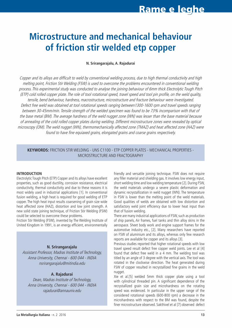
ETP Copper plates of 6mm thick, 200 mm in length and 100 mm in width were welded using computer controlled FSW machine. The plates were rigidly clamped on backup plate to produce butt joint. Before clamping the plates and the edges of the plates were properly cleaned with acetone. The tool was made of M2
high speed tool steel with taper threaded tool pin as shown in Fig. 1. The tool pin was hardened and tempered to obtain a hardness of 60 HrC. The tool dimensions are given in Table 2.
La Metallurgia Italiana - n. 2 2016 15
Rame e leghe
Three tool rotational speeds of 1300, 1400 and 1600 rpm and two welding speeds of 30 and 45 mm/min were used in this study. Tool pin was tilted by an angle of 30 to the vertical axis and rotated in the clockwise direction.The rotating tool pin was initially plunged at one end of the intended weld line and dwell time of 5 sec was allowed to generate adequate heat. Then the work table along with the work piece was made to traverse along the weld line. The schematic sketch of the weld specimen is shown in Fig. 2.
Fig. 2 - Friction stir welding of ETP copper plates(All dimensions in mm)
After FSW, the welds were visual examined to check the presence of visible surface defects. Microstructural examination was carried out on base material and few welded specimens to visualize the microstructural change at nugget zone and heat affected zone. The welded specimens without any visible defects were chosen and sliced into ASTM E8 sub-size standard tensile test specimens in CNC wire EDM. The dimensions of ASTM-E8 sub-size standard specimen is shown in Fig -3.
Fig. 3 - ASTME8 sub-size standard tensile test specimen(All dimensions in mm)
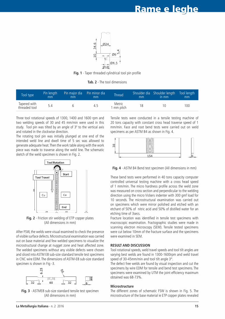
Tensile tests were conducted in a tensile testing machine of 20 tons capacity with constant cross head traverse speed of 1 mm/min. Face and root bend tests were carried out on weld specimens as per ASTM B4 as shown in Fig. 4.
Fig. 4 - ASTM B4 Bend test specimen (All dimensions in mm)
These bend tests were performed in 40 tons capacity computer controlled universal testing machine with a cross head speed of 1 mm/min. The micro hardness profile across the weld zone was measured on cross section and perpendicular to the welding direction using the micro Vickers indenter with 300 gmf load for 10 seconds. The microstructural examination was carried out on specimens which were mirror polished and etched with an etchant of 50% of nitric acid and 50% of distilled water for an etching time of 3secs.Fracture location was identified in tensile test specimens with macroscopic examination. Fractographic studies were made in scanning electron microscopy (SEM). Tensile tested specimens were cut below 10mm of the fracture surface and the specimens were examined in SEM.
ReSULT AND DISCUSSIONTool rotational speeds, weld travel speeds and tool tilt angles are varying best welds are found in 1300-1600rpm and weld travel speed of 30-45mm/min and tool tilt angle 3°.The defect free welds are found by visual inspection and cut the specimens by wire EDM for tensile and bend test specimens. The specimens were examined by UTM the joint efficiency maximum obtained was 68-73%.
MicrostructureThe different zones of schematic FSW is shown in Fig. 5. The microstructure of the base material ie ETP copper plates revealed
the presence of elongated large grains of length ranging between 60-70 µm and width of about 25-30 µm as shown in Fig. 6(a). Defect free welded joint with high joint strength was obtained at the tool rotational speed of 1300 rpm and welding speed of 30 mm/min and detailed microstuctural analysis on this weld joint was conducted. The microstructure of the nugget zone (NZ), thermomechanically affected zone (TMAZ), intermixing zone of WN and TMAZ and heat affected zone (HAZ) are shown in Fig. 6(b) (c) (d) (e) and (f). The microstructure of the nugget zone revealed that porosity or other defects are not present in the joints produced. Weld nugget has extremely fine equiaxed grains of size 4-6 µm due to dynamic recrystallization favoured by frictional heat and plastic deformation. This resulted softening
due to annealing and reduced the hardness compared to the parent metal. TMAZ was plastically deformed and thermally affected in the advancing and retreating sides unevenly as shown in Fig. 5(d). Hence, partially recrystallized grains of size ranging between 14-25 µm at advancing side and fine grains of size ranging between 6-10 µm at retreating side were observed. The intermixing zone in the advancing side is also shown in Fig -6(e). The nugget zone and TMAZ was clearly distinguished due to the presence of medium size grains of size 5-10µm in TMAZ. Whereas coarse grains ranging between 20-40 µm were observed in HAZ in Fig. 6 (f). Large size grains in BM, in WN the copper grains are very fine equaxed grains were found.
Fig. 5 - Transverse section of a friction stir weld showing different regions of the weld. HAZ, heat-affected zone; TMAZ, thermomechanically affected zone [Mishra]
Fig. 6 - Various microstructural zones of ETP copper by FSW(a) Microstructure of ETP Copper Base Metal (BM) showing elongated grains
(b) Microstructure of Weld Nugget (WN) showing fine equiaxed grains(c) Microstructure of Thermo Mechanically Affected Zone of advancing side (TMAZ)(d) Microstructure of Thermo Mechanically Affected Zone of retreating side (TMAZ)
(e) Microstructure of WN-TMAZ interface in the advancing side(f) Microstructure of Heat Affected Zone (HAZ)
Rame e leghe
La Metallurgia Italiana - n. 2 2016 17
Fig. 7 - Fracture location of tensile specimen
Bend test behaviourThe bend test was conducted on FSW specimens obtained on welding with the tool rotational speed of 1300rpm and traverse speed of 30mm/min. Both face and root bend tests were performed on the welded specimens for copper to copper. The samples showed that, face bend of the welded plate withstood a maximum load of 4.5 kN. Tensile specimens were tested the maximum elongation 19%. Bent test specimens were tested by three point bend test using UTM machine with cross head speed of 1mm/min and bend behaviour were studied. The cracks were observed on retreating side of HAZ shown in Fig. 8.
Tensile and Fracture behaviorTensile tests were conducted on the base metal and FSW specimens, the tensile properties such as proof stress, ultimate tensile strength, % of elongation the joint efficiency with reference to the UTS of base material were calculated and given in Table 3.The best combination of mechanical properties was obtained for a FSW joint obtained by tool rotational speed of 1300 rpm with a traverse speed of 30 mm/min in copper to copper weld. The tensile strength and percentage of elongation of the copper base
material were 333 MPa and 17% respectively. Whereas the tensile strength and elongation of the best FSW joint was observed to be 242 MPa and 19% respectively the weld efficiency was found to be 73%. On increasing the spindle rotational speed and the traverse speed to 1600rpm and 45 mm/min, the joint efficiency and elongation were found to be 71% and 18% respectively. In this case, the fracture location of the weld joint was in the HAZ of the retreating side as shown in Fig. 7, whereas in all other cases the fracture occurred along the weld line.
Tab. 3 - The welding parameters and the results of tensile tests.
MicrohardnessThe microhardness traverse plots across WN, HAZ and BM are shown in Fig. 9. In friction stir welding of copper, to copper weld nugget softening and reduction of hardness in the weld nugget was observed. The hardness of base metal ranged from 120-125 VHN, However, the hardness near the weld nugget showed values from 85-92 VHN. The weld nugget had slightly lower hardness than that of the base metal in spite of small grain size. The low hardness of nugget zone could be attributed to the effect of annealing on the cold worked base material during welding. In
Rame e leghe
La Metallurgia Italiana - n. 2 201618
a similar study Sun et. al [20] has also found a reduction in the hardness in WN. Lee et al (2003) also reported however the weld
of the copper exhibited minimum weak point just outside the WN as a result of complex annealing effect.
Fig. 10 - Tensile fractograph of the base metal (ETP Copper)(a) Low magnification, showing a fairly uniform appearance of the fracture surface
(b) High magnification, showing the dimples with deformed lips indicating considerable deformation prior to fracture.
Fig. 11 - Tensile fractographs of Copper specimens FSW with 1400 rPM and 30mm/min traverse speed.(a) Low magnification image showing three distinct layers
(b) Dimples in the middle layer indicating the fracture by void nucleation and growith.(c) High magnification image of location A showing a serrated fracture pattern at the interface
of middle and bottom layer and fine striations in the bottom layer
Fig. 9 - Copper to Copper Weld Microhardness
In order to analyzes the role of spindle speed and traverse speed, two fracture surfaces pertaining to low spindle speed/low traverse speed (1400rPM and 30mm/min), and high
spindle speed (1600rPM/high traverse speed 45mm/min) were examined in detail and shown in Fig. 11 and 12. Based on trial and error method were obtained the conclusion.
Rame e leghe
Fractographic AnalysisThe fracture surfaces of the tensile test specimens of the base material ETP copper, FS welded with 1400 rPM, 30mm/min and with 1600 rPM,45 mm/min were examined under SEM and the typical fractographis are shown in Fig 10-12 respectively.Fig. 10(a) shows the fractograph of the ETP copper specimen
tested in tension in the as received condition. The fracture pattern is uniformly dimple failure throughout the fracture face of the specimen. The high magnification fractograph, Fig. 10 (b) shows the presence of fairly large size dimples with deformed lips indicating considerable ductility.
La Metallurgia Italiana - n. 2 2016 19
The low magnification fractograph, Fig. 11(a) of specimen FS welded with low spindle speed (1400 rPM)/low traverse speed (30mm/min) reveals the presence of three distinct layers in the fracture surface. The three layered structure is attributed to the three threads in the tool pin. Though the spindle speed is sufficient to plasticize the copper at horizontal plane, it could not force the material to flow in vertical direction and hence a layered structure is resulted. However, it is to be noted that the top and bottom layers are relatively thin in comparison to the thick middle layer. This confirms the occurrence of homogeneous stirring and good welding in about 75% of the entire thickness. The high magnification fractograph obtained from the middle
layer, Fig. 11 (b) exhibits the presence of dimples with extensively deformed lips, which indicates the high degree of ductility due to good bonding. Whereas, the fractograph corresponds to the interface between the middle and the bottom layer (Fig. 11 c). shows a different fracture pattern across the interface. In contrast to the presence of dimples in the middle layer, indicating the void nucleation and coalescence, the fracture pattern transforms to a quasi shear fracture with serrations and at the edges with striated shear fracture. Shen et al.(2010), have also observed layered structure in the fractograph of FS Welded copper plates using a tool pin profile of taper cylindrical with threads.
Fig. 12 (a) shows the low magnification fractograph of the specimen FS welded with 1600rPM, 45mm/min traverse speed. This fractograph indicates a two layered fracture surface with diffused interface. The predominant failure pattern observed in the top layer is dimple fracture, indicating the adequate ductility and the occurrence of void nucleation and coalescence (Fig 12b). In view of high spindle speed, for about 80% of the thickness
from the top a near homogneous stirring could have occurred which in turn resulted a uniform fracture behavior in the top 80% regions. Whereas the fracture pattern transformed from pure dimple to quasi dimple and finally to shear fracture in the edges (Fig 12c).The comparison between the fracture behaviour of the specimens is given in Table 4.
Fig. 12 - Tensile fractographs of Copper specimens FSW with 1600 rPM and traverse speed 45mm/min.(a) Low magnification, showing a two layered fracture surface with diffused interface
(b) High magnification at the bottom region showing a mixed type of fracture with the presence of dimples indicating the ductile and the presence of flat regions indicating the brittleness
(c) High magnification at the middle region, showing dimples and voids indicating ductile fracture.
Tab. 4 - Comparison between the fracture behaviour of the specimens
Materials condition LocationFractograph
Low magnification High magnification
Base metal Middle river pattern Dimples
Weld- 1 HAZ Three layered Large dimples
Weld-2 HAZThree layered with broad middle layer
Fine dimples
CONCLUSIONSIn this study, ETP Copper was FS Welded using various spindle speeds (1300,1400 and 1600rPM), various traverse speed (30 and 45mm/min) with tool pin profile of taper cylindrical with threads. The microstructure, tensile, bend behaviours, hardness and fractographic analysis were carried out. The major conclusions of the study are Weld nugget of the FSW copper specimens showed fine equiaxed
grains of 4-6 micron size in comparison with the elongated grains of 60-70 µm the base metal.Tensile strength and joint efficiency ranging between 226-242 MPa and 68 - 73% respectively were observed in FS welded copper specimens.The tensile fracture occurred in the HAZ at the retreating side of the weld due to the presence of coarse grains. Hardness of the weld nugget (85 VHN) was lower than that
Rame e leghe
La Metallurgia Italiana - n. 2 201620
of base metal (120VHN), because of annealing effect during welding.In factography, presence of fine dimples were observed in most of the regions of FS welded ETP copper.
ACKNOwLeDGeMeNT Authors are grateful to DMrL, Hyderabad for providing Friction Stir Welding Machine for welding the samples and support for carrying out this work.
ReFeReNCeS[1] ASM Hand Book,(1993)., Vol.6, Welding, Brazing and
Soldering, pp 1872-1876, USA, [2] Thomas, W.M., Nicholas E.D .(1997) ‘Friction stir welding
for the transportation industries’ Materials & Design. Vol.18. pp.269-273
[3] Mishra r.S., and Ma Z.y. (2005) ‘ Friction Stir Welding and Processing’ Mater. Sci. Eng. Vol.50, pp. 1-78.
[4] Won-Bae Lee and Seung-Boo Jung,(2004) ,’The joint properties of copper by friction stir welding’ Vol.58.pp.1041-1046.
[5] Xie G. M, Ma Z.y and Geng L , (2007) Scripta Mater., Vol.57, pp 73-76.
[6] Liu H.J, Shen J.J, Huang y.X, Kuang L.y, Liu C and Li C (2009) , Sci. Technol. Weld. Join., Vol. 14, pp.577-83.
[7] Sakthivel, T., and Mukhopadhyay, J., (2007)., ‘Microstructure and mechanical properties of friction stir welded copper’, J. Mater. Sci., 2007, Vol.42, pp.8126-29.
[8] Lam. Suvarna raju and Adepu Kumar, (2013), ‘Microstructure and Mechanical characterization of friction stir welded copper’, Int. Journal of Adv. Trends in Comp. Sci. and Eng. Vol.2 pp.640-643
[9] Dhananjayulu Avula, ratnesh Kumar raj Singh, Dwivedi D.K, Mehta N.K., (2011) ‘Effect of Friction Stir Welding on Microstructural and Mechanical Properties of Copper Alloy’ World Academy of Science’, Engineering and Technology, Vol.74.pp 214-222
[10] Masoud Jabbari and Cem. C. Tutum, (2013), ‘Optimum rotation Speed for the Friction Stir Welding of Pure Copper’, SrN Materials Science ,Vol.2, pp1-5.
[11] Galvao I., Leal r.M., rodrigues D.M, Loureiro A (2013), ‘ Influence of tool shoulder geometry on properties of friction stir welds in thin copper sheets’ Vol.213. pp 129-135.
[12] Selvam S. K. and Parameshwaran Pillai ,T. (2013),’Comparative evaluation of performance of friction stir welding tool materials for joining ETP Copper, Vol.2.pp.60-70.
[13] Hwang, y.M. , Fan P.L., Lin C.H.,(2010) ,’ Experimental study on Friction Stir Welding of copper metals’ Journal of Material Processing Technology,Vol.210., pp 1667-1672.
14] Leal, r.M, (2010), ‘Effect of shoulder cavity and welding parameters on friction stir welding of thin copper sheets. Institute of Materials.
[15] Hwa Soon Park, Takahiro Kimura, Taichi Murakami, yoshitaka Nagano, Kazuhiro Nakata, Masao Ushio (2004),’ Microstructures and mechanical properties of friction stir welds of 60% Cu-40% Zn copper alloy’ Material Science and Engineering, pp 160-169.
[16] Sun , F. y and. Fujii ,H.,(2010),’Investigation of the welding parameter dependent microstructure and mechanical properties of friction stir welded pure copper’ Materials Science and Engineering A, Vol 527,pp6879-6886.
[17] Shen J.J. Liu H.J, Cui F, (2010),’ Effect of welding speed on microstructure and mechanical properties of friction stir welded copper’ Material and Design, pp 3937-3942.
[18] Xue. P., Xie G.M., Xiao B.L, Xiao, Ma Z.y and Geng L (2010),’Effect of Heat Input Conditions on Microstructure and Mechanical Properties of Friction –Stir –Welded Pure Copper’. The Minerals, Metals & Materials Society and ASM International.Vo. 41A.
[19] Khodaverdizadeh H., Mahmoudi A., Heidarzadeh A, Nazari E., (2012),’Effect of friction stir welding (FSW) Parameters on strain hardening behavior of pure copper joints. Materials and Design Vol.35. pp 330-334.