Page 1
28TH
INTERNATIONAL CONGRESS OF THE AERONAUTICAL SCIENCES
1
Abstract
Laser cladding (LC) was used to investigate the
repair of high strength steel in aircraft
applications, such as landing gears. This paper
reports on the microstructure and
microhardness properties of the deposited AISI
4340 clad layer on AISI 4340 steel substrate.
Microhardness results showed the clad layer
was 30-40% harder than the base material.
Stress relieving the clad allowed the clad and
HAZ areas to soften 10% below the base
material. High dilution provided a favorable
result on the hardness at the interface.
1 Introduction
High strength steels such as AISI 4340 are used
widely in aircraft, particularly in critical
applications such as landing gear. However they
are known to be vulnerable to corrosion, impact
and they are fracture-sensitive [1]. In aerospace
applications such as critical carry-through
structures, discovering even a small crack will
lead to the reduction in airworthiness, and it is
therefore vital to repair even small damage
features, or replace the component. A repair by
grinding out the damage may exceed
dimensional limits, and where this happens, and
in order for the aircraft to remain in service, it is
usual to replace the damaged component. As the
cost of replacing the component can be high,
potential methods for repair by rebuilding the
damaged area and restoring strength are of
interest.
A potential repair technology is laser
cladding. The concept is to melt a metal
powder, with appropriate mechanical properties,
using a laser beam, to form a track of solid
metal fused with the substrate material to form
a metallurgical bond [2]. There has been great
interest in using laser cladding as a repair
method for aerospace applications [3, 4].
Several researchers have reported on laser
cladding of high strength steel. Bhattacharya et
al. [5] has reported on the microstructural
features of laser clad AISI 4340 steel powder on
mild steel substrate powder on substrate. Other
research on AISI 4340 steel has involved in
laser melting application [6, 7]. Fastow et al.
[6] analysed the microstructural and
microhardness evolution of AISI 4340 steel
when laser melted using a 1.2kW CO2 laser.
McDaniels et al. [7] showed that the HAZ of a
laser melted AISI 4340 steel did not have an
adverse effect on the fatigue properties.
However, very little research has been
published on the repair of laser cladding of
aero-grade high strength steel. This paper
focuses on the mechanical properties of laser
cladding of AISI 4340 steel powder on AISI
4340 aero-grade steel substrate. Microstructural
features and microhardness properties are
analysed. The aim is to; (i) Identify
microhardness and microstructure evolution of
high strength steel. (ii) Effect of the laser
processing parameters on the microhardness and
microstructure.
2 Experimental details
MICROSTRUCTURE AND MECHANICAL PROPERTIES OF LASER CLADDING REPAIR OF AISI 4340 STEEL
Shi Da Sun*, Qianchu Liu**, ****, Milan Brandt*
, ****, Madabhushi Janardhana***, and
Graham Clark*
*RMIT University, **Defence Science Technology Organisation (DSTO), *** Directorate
General Technical Airworthiness (DGTA), **** Defence Material Technology Centre
(DMTC)
[email protected] ; [email protected]
Keywords: Laser cladding, AISI 4340 steel, microstructure
Page 2
Shi Da Sun, Qianchu Liu
2
2.1 Material preparation
AISI 4340 steel plates of dimension 180 mm x
100 mm x 6 mm (composition shown in Table.
1) were supplied in annealed condition The
plates were then heat-treated, in accordance
with ASM handbook [8], by quench hardening
and tempering to achieve a representative in-
service UTS level of 1400MPa.
Table. 1. Chemical compositions (in wt. %) of
the AISI 4340 base material as provided by
supplier. C Mn Ni Cr Si Mo V Fe
0.41 0.7 1.74 0.77 0.24 0.25 0.046 Bal
AISI 4340 powder was supplied by
Sandvik Osprey Ltd. in the form of gas
atomized spherical particles (-106+45µm).
2.2 Laser cladding
A 4kW IPG Photonics fibre laser with a co-axial
powder delivery head was used to deposit each
clad. A mixture of helium and argon was used
as both the carrier and shielding gas. The
shielding gas flow was 15L/min. A 16.0mm
standoff height (distance between the tip of the
cladding head and the melt pool) was used. The
cladding head was tilted 5° relative to the melt
pool in order to minimize any back reflections
from the melt pool damaging the laser.
Each plate was cladded in the direction of
rolling. A 5.0mm bead width and a 2.5mm
overlap were used to clad. The approximate
track length was 23mm.
2.3 Metallurgical procedure
Samples were cross-sectioned, mounted,
polished to 1.0μm finish and etched with a 4%
Nital solution, in accordance with standard
metallographic procedures [9]. Microscopic
examination was conducted using a Leica
MEF3 optical microscope.
Microhardness measurements were
performed using a LECO LM700AT micro-
hardness tester. An applied load of 300gf was
held for 15 seconds, in accordance with
standard ASTM procedure [10].
2.4 Experiment design
A total of three design conditions were used for
the analysis of microstructure and micro-
hardness: (i) Baseline (ii) clad layer with 2
different laser processing parameters (iii) post
heat treatment (PHT).
The laser processing parameters used for
repair are those that produce defect free clad
layer. Any clad defects such as porosity and
micro-cracking could act as damaging stress
concentrators and degrade the mechanical
properties of the material. Two laser processing
parameters are tested (Table. 2).
Table. 2. Laser processing parameters used
for this research.
No. Powder flow
rate (g/min)
Laser
speed
(mm/min)
Laser
power
(kW)
Laser
beam
diameter
(mm)
1 25 1400 4 5
2 20 800 4 5
The laser processing parameters were
determined from initial trials of AISI 4340 steel
cladding [11]. Since the aim was to determine
the optimum clad, no grind-out area was
employed in the initial trials. In Fig. 1a, the
clad/HAZ fusion line is where the red region
contacts the green region and dilution/HAZ
fusion line is where the yellow region contacts
the green region. The inconsistent dilution is
due to the Gaussian laser intensity distribution,
causing a higher temperature in the center of the
clad track, where most of the energy is supplied
[12]. Parameter 1 is a low dilution clad (Fig. 1b)
and parameter 2 is a high dilution clad (Fig. 1c).
Dilution (D) is the percentage of area that has
melted into the base material (Eq. 1).
Page 3
3
MICROSTRUCTURE AND MECHANICAL PROPERTIES OF LASER CLADDING REPAIR OF
AISI 4340 STEEL
Fig. 1. (a) Schematic of a cross-sectioned multi-
track clad (without grind-out) showing the 4
composite layers in a laser cladding process. (b)
Clad 1. (c) Clad 2.
It is often reported when laser cladding to
keep dilution to a minimum to minimize the
mixing between the clad layer and the substrate
in order to maintain the properties of the
baseline material [13]. However, high dilution
allows stronger bonding between the clad and
base material and in some case may have
beneficial properties [14]. It is known that in
laser cladding the weakest point is the clad/HAZ
interface due to inconsistent dilution/fusion [7,
15]. This research examines the effect of
dilution on the hardness and static strength
properties.
Residual stress and hardness variation
occur in laser cladding due to high thermal
gradients inherent in the process [16]. Residual
stresses in clad material could affect the
component’s resistance to corrosion and fatigue
cracks due to high thermal stress concentration.
Post heat treating reduces the generated stresses
at the clad/substrate interface and improves its
mechanical properties. Post heat treatment was
performed in accordance with ASM handbook
standard [17] The process involved heating the
clad plates to 560°C, and soaking for 3 hours
followed by slow cooling to 250°C over 5
hours, and finally air cooling.
3 Results & discussion
3.1 Microstructure properties
3.1.1 Microstructure of the clad
For low alloy steel, the solidification structure
consists of austenite dendrites and depending on
the cooling rate, various other phases. The
formation of a clad is dependent in part on the
heating time which is influenced by the laser
scan speed and is usually between 0.1-2 seconds
[18]. The cooling rates of laser cladding are
rapid usually between 103-10
6 k/s [19, 20]. For
such high cooling rates with AISI 4340 steel
material it is expected that the martensite
structure to dominate the clad. Bhattacharya et
al. [5] identified ferrite, martensite, and
cementite phases in the microstructure of an
AISI 4340 steel clad. Fastow et al. [6] showed
that decreasing dilution generally results in a
finer microstructure.
Fig. 2 shows that the clad layer consists of
austenitic dendrites (white lines) where the
growth is in the direction of solidification. Two
distinct dendrite structures appeared in one
single track clad; (i) cellular (Fig. 2a) and (ii)
columnar (Fig. 2b). Dendritic formation is
dependent on the heating and cooling rates.
Heating and cooling rates are much more rapid
near the surface [21] and temperature gradients
generally exist across the solidifying structure
resulting in the formation of different dendrites.
A fine martensitic phase appeared within the
dendrites due to rapid cooling rates. The black
needles are constituents of bainite.
The dilution zone is a mixture of melted
base material and clad powder. Since the
powder and base material have similar chemical
composition, the dilution zone has similar
microstructural features to the clad zone.
(a)
(b)
(c)
Page 4
Shi Da Sun, Qianchu Liu
4
Fig. 2. Clad 2 parameters-20g/min, 800mm/min,
4kW (a) clad zone showing dendritic cellular
structure (white lines) martensite (light grey
areas between the dendrites) and bainite (dark
needles) (b) clad zone with dendritic columnar
structure.
3.1.2 Microstructure of the Heat Affected Zone
The HAZ is a complex heat treated area
subjected to rapid heating with a short
interaction time, followed by air cooling at
room temperature during each pass. The heat
treatment is similar to rapid quenching in air but
using a range of heating temperatures. The HAZ
starts from the clad/HAZ interface (Fig. 1a)
where the peak temperature is just below the
melting temperature of 0.4wt%C steel which is
1500°C (AM) [22]. The temperature decreases
proportionally to the HAZ depth, where
according to the iron-carbon phase
transformation diagram (Fig. 3), for a 0.4wt%C
steel, the material will undergo γ and α phase
transformation (γ at 800°C-1500°C, γ + α at
727°C-800°C) until the HAZ reaches the
HAZ/baseline interface (Fig. 1a), where the
cooling temperature reaches below the eutectoid
temperature 727°C (A1) which is the minimum
temperature for γ transformation. Depending on
the cooling rate, a variety of constituents may
form such as martensite and bainite.
Fig. 3. Iron carbon transformation diagram. Red
line indicates the phase transformations for AISI
4340 steel [23].
Directly below the clad/HAZ interface,
where the peak temperature is just below AM,
the microstructure transformed to a coarser γ
and upon cooling, transformed to an acicular
ferrite (white needles) and lath
martensitic/bainite structure (grey/dark regions),
as shown in Fig. 4a. The martensite that formed
is generally brittle due to the rapid cooling rate
in air, and as a result, exhibits low ductility and
toughness [8]. The coarsening of the γ grains
near the clad/HAZ fusion line is due to high
peak temperatures and causing high kinetic
movement of atoms just adjacent to the
clad/HAZ fusion line [24]. The coarsened HAZ
caused significant grain growth, and as a result,
the constituents of ferrite transformed into a
more acicular appearance. The coarsening near
the clad/HAZ interface is observed in welding
[24] and other laser material processing where
high heating temperature is applied [6]. Further
away from the clad/HAZ interface, the grain
size becomes finer due to decreased
temperatures, and a traditional microstructure of
a rapid quench heat treatment is observed (Fig.
4b).
(a)
(b)
Page 5
5
MICROSTRUCTURE AND MECHANICAL PROPERTIES OF LASER CLADDING REPAIR OF
AISI 4340 STEEL
The HAZ/baseline interface is distinctly
identified (Fig. 4c), since transformation ceases
when the temperature falls below A1, where
austenite transformation stops. The dark region
is a microstructure of the baseline AISI 4340
steel prior to cladding. The white appearance in
Fig. 4a is due to α constituent, where the heating
temperature is just above A1, consisting of γ + α
transformation.
Fig. 4. Clad 2 parameters-20g/min, 800mm/min,
4kW. Microstructure evolution of the HAZ. (a)
0.2mm below the clad/HAZ interface. (b)
0.6mm below the clad/HAZ nterface. (c)
HAZ/baseline interface.
3.1.3 Microstructure of Post Heat Treated
(PHT) sample
The microstructure of the PHT clad and HAZ
consisted mainly of α constituent, which is
expected since the heating temperature of 560°C
causes α transformation (Fig. 5). The acicular
appearance of the ferrite is due to the longer
heating time of the PHT procedure. The HAZ
still maintained the coarsened γ grains near the
clad/HAZ fusion line, as shown in Fig. 5b-c,
which is expected since no γ transformation
occurs in tempering.
Fig. 5. Clad 2 parameters-20g/min, 800mm/min,
4kW. Microstructure of PHT of AISI 4340 steel
(a) clad (b) 0.2mm below the clad/HAZ
(a)
(b)
(a)
(b)
(c)
(c)
Page 6
Shi Da Sun, Qianchu Liu
6
interface (c) 0.6mm below the clad/HAZ
interface.
3.2 Microhardness properties
3.2.1 General microhardness
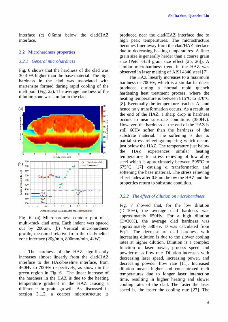
Fig. 6 shows that the hardness of the clad was
30-40% higher than the base material. The high
hardness in the clad was associated with
martensite formed during rapid cooling of the
melt pool (Fig. 2a). The average hardness of the
dilution zone was similar to the clad.
Fig. 6. (a) Microhardness contour plot of a
multi-track clad area. Each indent was spaced
out by 200µm. (b) Vertical microhardness
profile, measured relative from the clad/melted
zone interface (20g/min, 800mm/min, 4kW).
The hardness of the HAZ significantly
increases almost linearly from the clad/HAZ
interface to the HAZ/baseline interface, from
460Hv to 700Hv respectively, as shown in the
green region in Fig. 6. The linear increase of
the hardness in the HAZ is due to the heating
temperature gradient in the HAZ causing a
difference in grain growth. As discussed in
section 3.1.2, a coarser microstructure is
produced near the clad/HAZ interface due to
high peak temperatures. The microstructure
becomes finer away from the clad/HAZ nterface
due to decreasing heating temperatures. A finer
grain size is generally harder than a coarse grain
size (Petch-Hall grain size effect [25, 26]). A
similar microhardness trend in the HAZ was
observed in laser melting of AISI 4340 steel [7].
The HAZ linearly increases to a maximum
hardness of 700Hv, which is a similar hardness
produced during a normal rapid quench
hardening heat treatment process, where the
heating temperature is between 815°C to 870°C
[8]. Eventually the temperature reaches A1 and
hence no γ transformation occurs. As a result, at
the end of the HAZ, a sharp drop in hardness
occurs to near substrate conditions (380Hv).
However, the hardness at the end of the HAZ is
still 60Hv softer than the hardness of the
substrate material. The softening is due to
partial stress relieving/tempering which occurs
just below the HAZ. The temperature just below
the HAZ experiences similar heating
temperatures for stress relieving of low alloy
steel which is approximately between 595°C to
675°C [17] causing α transformation and
softening the base material. The stress relieving
effect fades after 0.5mm below the HAZ and the
properties return to substrate condition.
3.2.2 The effect of dilution on microhardness
Fig. 7 showed that, for the low dilution
(D=10%), the average clad hardness was
approximately 650Hv. For a high dilution
(D=30%), the average clad hardness was
approximately 580Hv. D was calculated from
Eq.1. The decrease of clad hardness with
increasing dilution is due to the slower cooling
rates at higher dilution. Dilution is a complex
function of laser power, process speed and
powder mass flow rate. Dilution increases with
decreasing laser speed, increasing power, and
decreasing powder flow rate [11]. Increased
dilution means higher and concentrated melt
temperatures due to longer laser interaction
time, resulting in higher heating and slower
cooling rates of the clad. The faster the laser
speed is, the faster the cooling rate [27]. The
(a)
(b)
Page 7
7
MICROSTRUCTURE AND MECHANICAL PROPERTIES OF LASER CLADDING REPAIR OF
AISI 4340 STEEL
hardness of steel decreases with longer cooling
rate due to the decrease in martensite.
Fig. 7. Vertical microhardness profile, measured
relative from the clad/melted zone interface
showing the effect of dilution.
Other researches have also reported a
variation of microhardness in a steel clad layer.
In Sun et al. [28], the cladding with AISI 420
stainless steel substrate and satellite 6 clad
showed the hardness of the clad is linearly
dependent on the percentage of dilution. The
hardness decreases linearly with increasing
dilution which was due to an altered chemical
composition of the clad layer from dilution.
Similar results were found by Yellup [29]. The
clad hardness of - stellite 6, Cenium Z20, and
Eutrolloy – all decreased linearly when the
dilution was greater than 10%. When the
dilution was less that 10 %, the hardness of the
clad was not altered.
Fig. 7 shows that at the melt zone/HAZ
interface, a sharp drop in microhardness is
experienced. For a low dilution, the hardness
dropped to 380Hv. For a high dilution, the
hardness dropped to 470Hv. The point measured
was at the maximum melt depth of the sample.
Since the cooling rate for a high dilution clad is
slower than that of a low dilution clad, which
means there was no time for grain growth to
occur and as a result, a finer microstructure and
a higher microhardness was obtained. High
dilution had a favorable effect on the
microhardness; (i) Clad is less brittle since the
hardness was reduced as dilution increases. (ii)
A smoother hardness transition occurs at the
melted zone/HAZ interface. For low dilution, a
high hardness differential is experienced where
the hardness sharply drops from 650Hv to
380Hv. This differential of hardness acts as
stress concentrator, which will degrade fatigue
properties and also cause failure at the interface
such as delamination.
3.2.3 The effect of PHT on microhardness
After PHT, both the clad and HAZ hardness
decreased by 40% to 400Hv, which was
approximately 40Hv below the hardness of the
base material (Fig. 8). Since the coarsening of γ
in the HAZ still exists, the HAZ maintained the
linear increase of hardness, but only from
400Hv to a maximum of 460Hv at the end of
the HAZ. A smooth hardness transition is
experience at all the interfaces. PHT did not
affect the hardness of the base material.
Fig. 8. Vertical microhardness profile, measured
relative from the clad/melted zone interface
showing the effect of PHT.
4 Conclusion
This study investigated the deposition of AISI
4340 steel powder on AISI 4340 high strength
steel plate using laser cladding. Following
conclusion can be made:
The clad layer primarily consists of
austenitic dendrites and fine martensitic
and bainite structure, while the HAZ
contained coarse austenite and an
acicular martensitic/ bainitic structure.
The hardness of the clad is 30-40%
higher than the base material.
Page 8
Shi Da Sun, Qianchu Liu
8
Increasing dilution has a favourable
effect on the hardness at the melted
zone/HAZ interface.
Increasing dilution from 10% to 30%
decreases the average clad hardness from
650 to 580Hv.
PHT decreased both the clad and HAZ
hardness to 400Hv. A smooth hardness
transition is experience between clad,
HAZ and substrate.
5 Acknowledgement
The authors wish to acknowledge the financial
and technical support of the Defence Science
and Technology Organisation (DSTO) and
Directorate General Technical Airworthiness
(DGTA). In addition, the authors are indebted to
the Industrial Research Institute Swinburne
(IRIS), and Hardchrome Engineering for their
assistance during the laser cladding trials.
References
[1] Hebsur M. Recent attempts of improving the
mechanical properties of AISI 4340 steel by control
of microstructure — A brief review, Journal of
Materials for Energy Systems. Vol. 4, No. 1, pp 28-
37, 1982.
[2] Sexton L, Lavin S, Byrne G and Kennedy A. Laser
cladding of aerospace materials, Journal of Materials
Processing Technology. Vol. 122, No. 1, pp 63-68,
2002.
[3] Liu Q, Janardhana M, Hinton B, Brandt M and Sharp
K. Laser cladding as a potential repair technology for
damaged aircraft components, International Journal
of Structural Integrity. Vol. 2, No. 3, pp 314-331,
2011.
[4] Brandt M, Sun S, Alam N, Bendeich P and Bishop A.
Laser cladding repair of turbine blades in power
plants: from research to commercialisation,
International Heat Treatment and Surface
Engineering. Vol. 3, No. 3, pp 105-114, 2009.
[5] Bhattacharya S, Dinda G P, Dasgupta A K and
Mazumder J. Microstructural evolution of AISI 4340
steel during Direct Metal Deposition process,
Materials Science and Engineering: A. Vol. 528, No.
6, pp 2309-2318, 2011.
[6] Fastow M, Bamberger M, Nir N and Landkof M.
Laser surface melting of AISI 4340 steel, Materials
Science and Technology. Vol. 6, No. 9, pp 900-904,
1990.
[7] McDaniels R L, White S A, Liaw K, Chen L, McCay
M H and Liaw P K. Effects of a laser surface
processing induced heat-affected zone on the fatigue
behavior of AISI 4340 steel, Materials Science and
Engineering: A. Vol. 485, No. 1-2, pp 500-507, 2008.
[8] Bates C E, Wisti M and Hingwe M. Quenching &
tempering of steel, Heat Treating, ASM Metals
Handbook. Vol. 4, No. 1, pp 160-324, 1991.
[9] Bramfitt B L and Lawrence S J. Metallography and
Microstructures of Carbon and Low-Alloy Steels,
Metallography and Microstructures, ASM Metals
Handbook. Vol. 9, No. 1, pp 608–626, 2004.
[10] ASTM Designation. E 384 Standard test method for
microindentation hardness of materials. ASTM
International. 1999.
[11] Sun S D, Brandt M, Liu Q, Janardhana M and Clark
G. Process optimisation of laser assisted metal
deposition of Aero-grade AISI 4340 steel, (To be
published), 2012.
[12] deLange D F, Hofman J T and Meijer J. Influence of
intensity distribution on the meltpool and clad shape
for laser cladding, Proceedings of the Third
International WLT-Conference on Lasers in
Manufacturing, Munich, Vol. 1, pp 1-5, 2005.
[13] Steen W M. Laser material processing. 3rd edition.
Springer, 2003.
[14] Schneider M F. Laser cladding with powder; Effect
of some machining parameters on clad properties,
University of Twente, Ph.D Thesis, Enschede, The
Netherlands, 1998.
[15] Pinkerton A, Wang W and Li L. Component Repair
Using Laser Direct Metal Deposition, Proceedings of
the Institution of Mechanical Engineers, Part B:
Journal of Engineering Manufacture. Vol. 222, No.7,
pp 827-836, 2008.
[16] Bendeich P, Alam N, Brandt M, Carr D, Short K,
Blevins R, Curfs C, Kirstein O, Atkinson G, Holden
T and Rogge R. Residual stress measurements in
laser clad repaired low pressure turbine blades for the
power industry, Materials Science and Engineering:
A. Vol. 437, No. 1, pp 70-74, 2006.
[17] Canonico D A. Stress-Relief Heat Treating of Steel,
Heat Treating, ASM Metals Handbook. Vol. 4, No. 1,
pp 81-84, 1991.
[18] Ion J C. Laser Processing of Engineering Materials:
Principles, Procedure and Industial Application.
Elsevier Butterworth-Heinmann, 2005.
[19] Vilar R. Laser cladding, Journal of Laser
Applications. Vol. 11, No. 2, pp 64-79, 1999.
[20] Ye X, Ma M, Liu W, Li L, Zhong M, Liu Y and Wu
Q. Synthesis and Characterization of High-Entropy
Alloy AlXFeCoNiCuCr by Laser Cladding, Advances
in Materials Science and Engineering. Vol. 1, 2011.
[21] Aliya D and Lampman S. Physical metallurgy
concepts in interpretation of microstructures,
Metallography and Microstructures in ASM Metal
Handbook. Vol. 9, No. 1, pp 44–70, 2004.
Page 9
9
MICROSTRUCTURE AND MECHANICAL PROPERTIES OF LASER CLADDING REPAIR OF
AISI 4340 STEEL
[22] Alloy Digest. ASM SA-14 AISI 4340 - Nickel
Chromium Molybdenum Alloy Steel. ASM
International. 1965.
[23] ASM Metals Handbook. Volume 1: Properties and
selection irons steels and high performance alloys.
ASM International. 1993.
[24] Vishnu P R. Solid-state transformation in weldment,
Welding, Brazing, and Solderi in ASM Metals
Handbook. Vol. 6, No. 1, pp 177-229, 2004.
[25] Hall E O. The deformation nd aging of mild steel,
Proceedings of the Physical Society B. Vol. 63, 747-
752, 1951.
[26] Petch N J. The cleavage strength of polycrystals,
Journal of Iron and Steel Institution. Vol. 174, 25-28,
1953.
[27] Kim J D and Peng Y. Temperature field and cooling
rate of laser cladding with wire feeding, Journal of
Mechanical Science and Technology. Vol. 14, No. 8,
pp 851-860, 2000.
[28] Sun S, Durandet Y and Brandt M. Parametric
investigation of pulsed Nd: YAG laser cladding of
stellite 6 on stainless steel, Surface and Coatings
Technology. Vol. 194, No.2-3, pp 225-231, 2005.
[29] Yellup J M. Laser cladding using the powder blowing
technique, Surface and Coatings Technology. Vol.
71, No. 2, pp 121-128, 1995.
Copyright Statement
The authors confirm that they, and/or their company or
organization, hold copyright on all of the original material
included in this paper. The authors also confirm that they
have obtained permission, from the copyright holder of
any third party material included in this paper, to publish
it as part of their paper. The authors confirm that they
give permission, or have obtained permission from the
copyright holder of this paper, for the publication and
distribution of this paper as part of the ICAS2012
proceedings or as individual off-prints from the
proceedings.