James L. Smialek Glenn Research Center, Cleveland, Ohio Anita Garg The University of Toledo, Toledo, Ohio Microstructure and Oxidation of a MAX Phase/Superalloy Hybrid Interface NASA/TM—2014-216679 July 2014 https://ntrs.nasa.gov/search.jsp?R=20150000193 2019-03-08T05:03:56+00:00Z
Transcript
James L. SmialekGlenn Research Center, Cleveland, Ohio
Anita GargThe University of Toledo, Toledo, Ohio
Microstructure and Oxidation of a MAXPhase/Superalloy Hybrid Interface
James L. SmialekGlenn Research Center, Cleveland, Ohio
Anita GargThe University of Toledo, Toledo, Ohio
Microstructure and Oxidation of a MAXPhase/Superalloy Hybrid Interface
NASA/TM—2014-216679
July 2014
Acknowledgments
Level of Review
NASA/TM—2014-216679 1
Microstructure and Oxidation of a MAX Phase/Superalloy Hybrid Interface
James L. Smialek
National Aeronautics and Space Administration Glenn Research Center Cleveland, Ohio 44135
Anita Garg
The University of Toledo Toledo, Ohio 43606
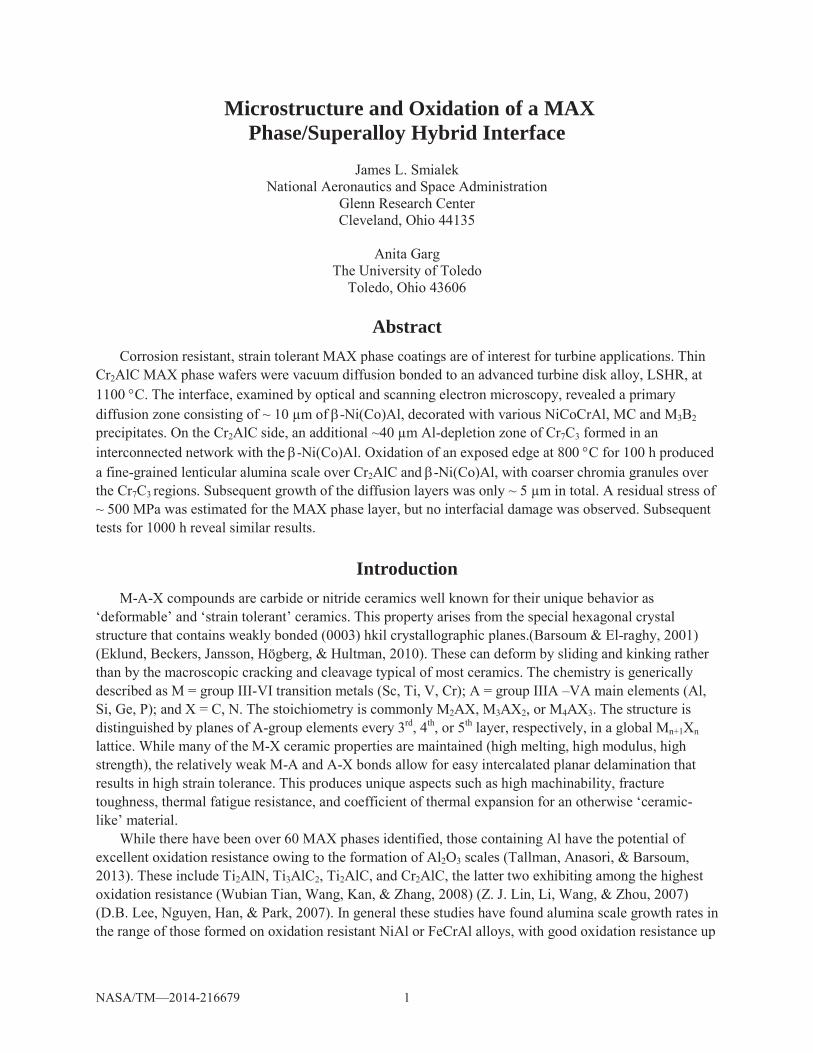
Abstract Corrosion resistant, strain tolerant MAX phase coatings are of interest for turbine applications. Thin
Cr2AlC MAX phase wafers were vacuum diffusion bonded to an advanced turbine disk alloy, LSHR, at 1100 C. The interface, examined by optical and scanning electron microscopy, revealed a primary diffusion zone consisting of ~ 10 μm of -Ni(Co)Al, decorated with various NiCoCrAl, MC and M3B2 precipitates. On the Cr2AlC side, an additional ~40 μm Al-depletion zone of Cr7C3 formed in an interconnected network with the -Ni(Co)Al. Oxidation of an exposed edge at 800 C for 100 h produced a fine-grained lenticular alumina scale over Cr2AlC and -Ni(Co)Al, with coarser chromia granules over the Cr7C3 regions. Subsequent growth of the diffusion layers was only ~ 5 μm in total. A residual stress of ~ 500 MPa was estimated for the MAX phase layer, but no interfacial damage was observed. Subsequent tests for 1000 h reveal similar results.
Introduction M-A-X compounds are carbide or nitride ceramics well known for their unique behavior as
‘deformable’ and ‘strain tolerant’ ceramics. This property arises from the special hexagonal crystal structure that contains weakly bonded (0003) hkil crystallographic planes.(Barsoum & El-raghy, 2001) (Eklund, Beckers, Jansson, Högberg, & Hultman, 2010). These can deform by sliding and kinking rather than by the macroscopic cracking and cleavage typical of most ceramics. The chemistry is generically described as M = group III-VI transition metals (Sc, Ti, V, Cr); A = group IIIA –VA main elements (Al, Si, Ge, P); and X = C, N. The stoichiometry is commonly M2AX, M3AX2, or M4AX3. The structure is distinguished by planes of A-group elements every 3rd, 4th, or 5th layer, respectively, in a global Mn+1Xn lattice. While many of the M-X ceramic properties are maintained (high melting, high modulus, high strength), the relatively weak M-A and A-X bonds allow for easy intercalated planar delamination that results in high strain tolerance. This produces unique aspects such as high machinability, fracture toughness, thermal fatigue resistance, and coefficient of thermal expansion for an otherwise ‘ceramic-like’ material.
While there have been over 60 MAX phases identified, those containing Al have the potential of excellent oxidation resistance owing to the formation of Al2O3 scales (Tallman, Anasori, & Barsoum, 2013). These include Ti2AlN, Ti3AlC2, Ti2AlC, and Cr2AlC, the latter two exhibiting among the highest oxidation resistance (Wubian Tian, Wang, Kan, & Zhang, 2008) (Z. J. Lin, Li, Wang, & Zhou, 2007) (D.B. Lee, Nguyen, Han, & Park, 2007). In general these studies have found alumina scale growth rates in the range of those formed on oxidation resistant NiAl or FeCrAl alloys, with good oxidation resistance up
NASA/TM—2014-216679 2
to 1300 C for Ti3AlC2 and Ti2AlC and 1200 C for Cr2AlC (Tallman et al., 2013). Ti2AlC has been characterized as having good cyclic oxidation resistance because of its good thermal expansion match to that of the alumina scale. The higher CTE of Cr2AlC leads to an increased spallation tendency similar to that observed for metals, but at much higher temperatures.
Furthermore, studies document good corrosion resistance of Ti3AlC2 and Cr2AlC in SO2 environments (Dong Bok Lee & Park, 2011) (Dong Bok Lee, Nguyen, & Park, 2011). Also, hot corrosion resistance was demonstrated in molten Na2SO4 salt for Cr2AlC (Z. Lin, Zhou, Li, & Wang, 2006a), and for Ti3AlC2, but only if preoxidized (Z. Lin, Zhou, Li, & Wang, 2006b). Thus the production of MAX phases as protective coatings for stainless steel, Ni-base superalloy M38G, Ti6242, and TiAl substrates has been demonstrated, primarily via magnetron sputtering (Eklund et al., 2010) (Walter, Sigumonrong, El-Raghy, & Schneider, 2006)( (Gulbiski, 2004)(Hajas et al., 2011) (Wang, Flores Renteria, et al., 2010)(Wang, Mykhaylonka, et al., 2010) (Li, Li, Xiang, Lu, & Zhou, 2011).
Emerging problem areas of environmental degradation in turbines are gas phase embrittlement, oxidation, and low temperature hot corrosion (LTHC) of advanced disk alloys used in the high pressure turbine stage. (Woodford, 2006) (Birbilis & Buchheit, 2008)(Sudbrack et al., 2012) (Encinas-Oropesa et al., 2008)(Sumner, Encinas-Oropesa, Simms, & Oakey, 2011) (Karabela et al., 2011)(Sato, Chiu, & Reed, 2011)(Moverare & Johansson, 2010) (Cruchley, Evans, Taylor, Hardy, & Stekovic, 2013). This is an especially sensitive application in that the surface of the disk and blade attachment points represent the most highly stressed areas of a turbine. Accordingly, crack tip oxidation has experienced in-depth attention (Kitaguchi et al., 2013)(Karabela, Zhao, Lin, Tong, & Hardy, 2013). Typical metallic aluminide and NiCrAlY coatings, engineered for higher temperature blade exposures and Type II hot corrosion resistance, actually lead to fatigue debits because of CTE mismatch stresses, lower strength, and tendency for brittle behavior in a disk environment. This warrants modified approaches, such as fully ductile Ni-Cr coatings or fatigue resistant, refractory strengthened NiCrAl-Ta,W “EQ” coating alloys (Mercer, Kawagishi, Tomimatsu, Hovis, & Pollock, 2011).
We therefore propose that Cr2AlC may be worth considering as a potential coating in this application. It has three desirable attributes: strain tolerance due to microlaminate kinking, a relatively high CTE (13 10-6/ C), and good Type I hot corrosion resistance. Our current studies indicate good Type II low temperature corrosion behavior as well. However little information is available regarding cyclic thermal stability of this coating with a superalloy. Thus the purpose of the present paper is to examine the compatibility of a hot pressed Cr2AlC-LSHR disk alloy hybrid after repeated cycling to 800 C. Interfacial mechanical, oxidative, and diffusional stabilities are the primary focus points.
Materials and Procedure The alloy portion of the couple was LSHR (Low ’ Solvus temperature, High Refractory) developed
by NASA for disk applications (Timothy P Gabb, Gayda, Telesman, & Kantzos, 2005). The AF-LSHR composition is:
Production scale powder metallurgy disks were produced by argon atomized, consolidated, hot compacted powders, followed by extrusion and isothermal forging. Specimen blanks were supersolvus heat treat at 1171 C for 2 h, cooled at 72 C/min., then aged at 855 C/4 h and 775 C/8 h. Phase constituents were primarily -Ni(Co,Cr,Mo,W) solid solution, strengthened by dense -Ni(Ti,Ta,Nb)3Al precipitates, and dispersed (Ta,Nb,Ti)C carbide, coarse (W,Mo,Cr)3B2 boride, and fine grain boundary (W,Cr)23C6 carbide particles. (T P Gabb & Miller, 2012).
NASA/TM—2014-216679 3
The starting Cr2AlC MAX phase ingot, approximately 2- by 2- by 12-cm, was obtained from Sandvik/Kanthal. As-received density was ~67% based on an assumed theoretical density of 5.22 g/cm3. Thus an effort was made to improve density by hot pressing in vacuum (77 Pa or 10-6 torr) using graphite dies. It was found that hot pressing at 1300 C for 2 h using 35 MPa pressure resulted in 97% density. The phase constituency was estimated by XRD Reitveld analyses to be ~92.3% Cr2AlC, 3.9% Al2O3, and 3.8% Cr7C3 which did not change appreciably in bulk with 1300 C hot pressing, 1100 C diffusion bonding, or 800 C oxidation.
Coupons ~ 6- by 12-mm were sectioned from the hot pressed Cr2AlC and LSHR using a diamond wafer saw. Thickness was ~ 0.3 and 1.8 mm, respectively. These were polished to 2400 grit SiC emery finish and vacuum hot pressed at 1100 C for 4 h under 85 MPa pressure (DC2). Hot pressing caused substantial deformation of the LSHR alloy, to the extent that the slightly undersized Cr2AlC layer was fully impressed into the metal. For this reason a second couple (DC3) was prepared for a subsequent 1000 h oxidation test, using 1.5 mm Cr2AlC and only 50 MPa pressure. Only minimal deformation of the LSHR alloy was noted. Grafoil mold release was burned off at 800 C for 1 h, and one end of the couple was sectioned for as-diffusion bonded metallography.
The cut edge and major surfaces were polished to 4000 grit emery and ultrasonically cleaned in ethanol. The couple was oxidized at 800 C in air for 100 h in a Thermolyne resistance muffle furnace, with intermittent removal for weight change and optical photography. The materials were analyzed by conventional metallographic, X-ray diffraction (XRD), and scanning electron microsopy (SEM) techniques before and after oxidation. SEM samples were coated with a conductive carbon or Au-Pd coating. Because of fine particle sizes and carbon coating, more quantitative assessments of carbide phases and thin oxide nodules were not attempted. Vacuum infiltrated epoxy mounted and polished cross-sections were prepared before and after oxidation. An additional feature of this study was the examination of surface scales formed on the edge, which had been pre-polished to 4000 grit emery, to show microstructural evolution of the scales across the interfacial bond.
Results The weight change behavior of the diffusion bonded hybrid couples are shown in Figure 1(a). Very
little oxidation occurred, gaining only 0.09 mg/cm2 after 100 h. This would be equivalent to a low parabolic rate constant of 7.23 10–5 mg2/cm4/h for the couple, although cubic kinetics may ultimately be a more accurate description of layer growth rates (Tallman et al., 2013). However, both the Cr2AlC and LSHR alloy contribute to this value, so it is impossible to precisely characterize the weight change contribution of either. The weight change of the second couple was oxidized in a similar matter and achieved only 0.17 mg/cm2 after 1000 h. There were no signs of delamination or deterioration of the bond interface. The literature suggests weight changes on the order of 0.061 and 0.20 for Cr2AlC oxidized for 100 and 1000 h, respectively,(Z. J. Lin et al., 2007) and ~0.31 and 0.57 mg/cm2 for LSHR oxidized for 100 and 1000 h, respectively. (T. P. Gabb, Sudbrack, Draper, MacKay, & Telesman, 2014). Since weight gain is not a focus of this study, the kinetics are not discussed in more detail.
XRD analyses of the oxidized surfaces is presented in Table 1. The Cr2AlC side formed primarily -Al2O3, with an increase in the Cr7C3 phase. Also, another Cr3C2 carbide depletion phase was identified.
The LSHR side formed primarily an -Cr2O3 scale with some (Ti,Ta,Cr)O6 tetragonal rutile-type oxide.
NASA/TM—2014-216679 4
TABLE 1.—XRD SURFACE ANALYSIS OF HYBRID COUPLE OXIDIZED 100 h AT 800 C MAX phase
Chemical formula Compound name Crystal system Ref. code Relative intensity Cr2AlC MAX phase Hexagonal 04-007-2697 StrongAl2O3 -alumina Rhombohedral 01-089-7716 Weak Cr7C3 chrome carbide Orthorhombic 01-089-5902 StrongCr3C2 chrome carbide Orthorhombic 04-004-4541 Weak
LSHR Chemical formula Compound name Crystal system Ref. code Relative intensity
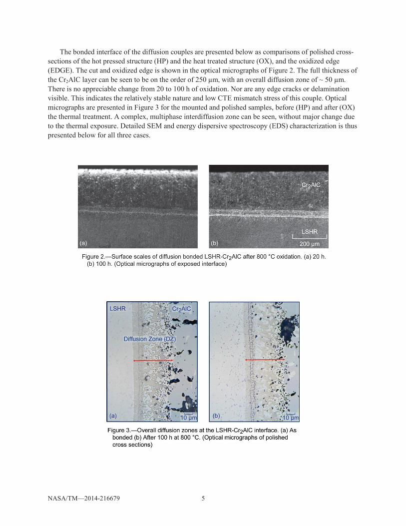
The bonded interface of the diffusion couples are presented below as comparisons of polished cross-sections of the hot pressed structure (HP) and the heat treated structure (OX), and the oxidized edge (EDGE). The cut and oxidized edge is shown in the optical micrographs of Figure 2. The full thickness of the Cr2AlC layer can be seen to be on the order of 250 μm, with an overall diffusion zone of ~ 50 μm. There is no appreciable change from 20 to 100 h of oxidation. Nor are any edge cracks or delamination visible. This indicates the relatively stable nature and low CTE mismatch stress of this couple. Optical micrographs are presented in Figure 3 for the mounted and polished samples, before (HP) and after (OX) the thermal treatment. A complex, multiphase interdiffusion zone can be seen, without major change due to the thermal exposure. Detailed SEM and energy dispersive spectroscopy (EDS) characterization is thus presented below for all three cases.
NASA/TM—2014-216679 6
Away from the interface, LSHR and Cr2AlC structures are characterized as unaffected endpoints. LSHR presented in Figure 4 shows densely populated, fine -Ni3Al precipitates (#5,2) in both HP and OX polished samples. They are only slightly distinguished in baskscattered electron (BSE) images (4) because of the atomic weight similarity to the -Ni(ss) matrix, and not appreciably altered by the 800 C, 100 h oxidation treatment. In contrast, sparsely distributed submicron (Ta,Nb,Ti)C carbide particles (#4,1) are easily distinguished because of their high refractory metal content. The corresponding LSHR region of the oxidized edge exhibits a profusion of Al,Cr,Ti,Ni-rich oxide nodules with faceted and needle-like surface crystals, Figure 5, with no obvious correlation with substrate microstructure. The various features characterized by EDS obtained at 15 kV are summarized in Table 2 and catalogued by feature number and exposure. Here EDS relative peak intensities are indicated in order of decreasing level, with indicating a difference of more than 15% and indicating a difference of more than 50%. Representative spectra will be presented later. Thus the unaffected LSHR alloy exhibits a Ni-rich matrix with low levels of all the alloying elements (#5), while the various carbides are rich in Ti, Cr, or refractory metals (#4). The LSHR scale features were rich in Al, Cr, Ti, Ni. Except for the Al-rich scale, this was consistent with XRD analyses that identified Cr(Ti)2O3 corundum patterns.
TABLE 2.—SEM/EDS FEATURE ANALYSIS AND EXPOSURE EFFECTS (COLOR CODING BY SIMILAR ITEMS). FEATURES ARRANGED FROM LSHR TO Cr2AlC
.
Point Polished cross-sections: HP P025 As-Hot Pressed
Point Polished cross-sections: OX P026 After Oxidation
LSHR 4 grey particle Ta>(Ni,Nb,Ti)>C>(Al,Cr,Co) MC 2 g.b. precipitate Ni>>(Al,Ti,W,Co,Cr)
LSHRDZ 9 grey particle Ta>(Nb,Ti)>>C MC 6 grey particle Ta>(Nb,Ti)>C>(Cr,Ni,Co) MC A nodule needles O>Ti>(Al,)Cr>>Ni TiO2
LSHRDZ 7 needle Ni>>(Al,Cr)>(W,Mo,Ti) TCP B flat base Al>(Cr,Ni)>(Co,O)>Ti>(Ta,W) Ni(Al,Cr)2O4
LSHRDZ 8 matrix Ni>>Cr>(Al,Co)> Ti / C nodule needles O>(Ti,Al,Cr)>(Ni,Co,O)>(Ta,W) (Al,Cr)TiO4
DZLSHR 6 white particle W>>(Mo,Cr)>(Ti,C) M3B2 5 D.Z matrix (Ni,Al)>>>(Co,Cr,Ti) -NiAl G nodule O>Cr>Ti>(Ta,Al) CrTiO4
DZLSHR 7 grey particle Ta>(Ti,Nb)>>(Ni,Al,C) MC 3 white particle W>(Mo,Cr)>C M3B2 H faceted nodule O>(Al,Cr,Ti)>>(Ni,Co) (Al,Cr)2O3 -CrTiO4
DZLSHR 8 underlayer Ni>Al>>(Cr,Co,Ti) -NiAl 4 grey particle Ni>Al>(Cr,Co)>(W,Mo,Ti) D flat base Al>O>(Cr,Ni,Co)>(Ti,Ta,W)
DZ1Cr2AlC 13 dark particle Al>>O>(Ni,Ti,Cr,Co) Al2O3 9 dark bond line particle Al>>O>(Ti,Ta,Nb,Cr,Co) Al2O3 E flat layer Al>>(O,Cr,Ni)>(Co,Ti,Ta,W) Al2O3
DZ1Cr2AlC 12 light phase (Ta,Ti)>(Al,Nb)>(Ni,C) MC 11 light phase (Ta,Ti)> (Al,Nb)>(Ni,C)>Cr,Co MC F smooth nodule (Al,O)>Cr>Ti>(Ni,Co)>(W,Ta) (Al,Cr,Ti)2O3
DZ1Cr2AlC 11 underlayer Ni>Al (Cr,Co) / 10 grey particle Ti>W>Nb>Mo>(C,Al)>>(Ni,Co,Cr) MC I sea urchin Al>O>Ti>Cr>(Ni,Co,W,Ta) Al2O3
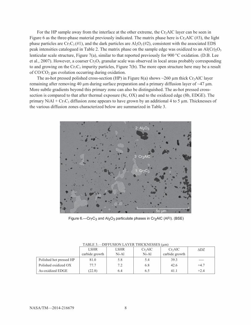
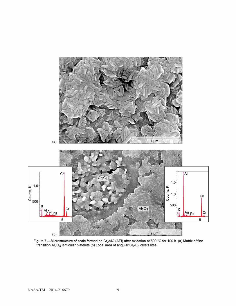
For the HP sample away from the interface at the other extreme, the Cr2AlC layer can be seen in Figure 6 as the three-phase material previously indicated. The matrix phase here is Cr2AlC (#3), the light phase particles are Cr7C3 (#1), and the dark particles are Al2O3 (#2), consistent with the associated EDS peak intensities catalogued in Table 2. The matrix phase on the sample edge was oxidized to an Al(Cr)2O3 lenticular scale structure, Figure 7(a), similar to that reported previously for 900 C oxidation. (D.B. Lee et al., 2007). However, a coarser Cr2O3 granular scale was observed in local areas probably corresponding to and growing on the Cr7C3 impurity particles, Figure 7(b). The more open structure here may be a result of CO/CO2 gas evolution occurring during oxidation.
The as-hot pressed polished cross-section (HP) in Figure 8(a) shows ~260 μm thick Cr2AlC layer remaining after removing 40 μm during surface preparation and a primary diffusion layer of ~47 μm. More subtle gradients beyond this primary zone can also be distinguished. The as-hot pressed cross-section is compared to that after thermal exposure (8c, OX) and to the oxidized edge (8b, EDGE). The primary NiAl + Cr7C3 diffusion zone appears to have grown by an additional 4 to 5 μm. Thicknesses of the various diffusion zones characterized below are summarized in Table 3.
Interfacial details are further compared in Figures 9 to 11 with EDS descriptions of labeled specific
features listed in Table 2. On the LSHR alloy side (left) for the as-hot pressed interface (HP), Ta(Ti,Nb) rich carbides (#9,7) are observed in both the Ni-rich alloy matrix (#5) and in the NiAl primary diffusion zone (#8), Figure 9. Larger, bright W-rich borides (#6) are also in this region. The original bond line (B.L.) is indicated by the dashed yellow line, decorated by the fine dark Al2O3 precipitates (#13). Moving toward the Cr2AlC layer, light (Ta,Ti)C carbides (#12) are again seen in an NiAl matrix (#11). Moving further right, a high volume percent of a light amorphic Cr-rich phase is present, probably a diffusional growth of the Cr7C3 impurity phase. This phase is well known to be a sublayer diffusion zone that grows under the alumina scale as Al is extracted from Cr2AlC during oxidation. (D.B. Lee et al., 2007)(Z. J. Lin et al., 2007). Also, it has been predicted thermodynamically and shown experimentally that NiAl will deplete Al from Cr2AlC to form Cr7C3 (Hajas, et al. 2010). Given that the high content of Al in Cr2AlC is likely to diffuse into the Ni-based LSHR alloy, Cr7C3 might also be expected as a depletion zone in an LSHR- Cr2AlC couple.
NASA/TM—2014-216679 11
NASA/TM—2014-216679 12
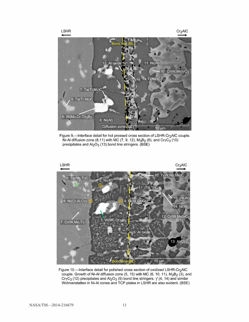
Figure 10 shows the interfacial details after oxidation in a mounted and polished cross section (OX). Features similar to those before oxidation are identified: Ta(Ti,Nb) MC carbides in LSHR (#6,11), Ni-Al primary diffusion zone (#5), bright W-rich borides (#3), fine Al2O3 precipitates (#9), and amorphic Cr7C3 colonies (#12). Some additional features are now apparent. A Cr(W,Mo,Ti)- rich acicular phase (#7) is present in the LSHR side, probably . And a weakly Widmanstätten Ni-Al precipitate (#4,14) appeared in the Ni-Al primary diffusion zone (#5,15). Semi-quantitative analysis of the primary diffusion zone yielded Ni-13Co-38Al, consistent with hypostoichiometric -NiAl. A grey carbide particle near the LSHR interface was estimated as 37Ti-17Ta-26Nb (carbon excluded from analysis). The fine 0.5 μm precipitates in the NiAl matrix varied considerably, with typical estimates near 30Ni-20Co-20Al-20Cr-3Ti, but not immediately suggestive of any common alloy phase.
Scale features of this interface area in the exposed edge are presented in Figure 11. Although a planar boundary can be discerned, there is no sign of bond line degradation. The fine particles at the bond line (B.L.) and many of the dark Al2O3 precipitates appear to have been masked by the scale features, while other structural variations and gradients remain. In general, flat Al-rich oxide (#D,E) formed over the NiAl diffusion zone with numerous nodule-type structures. On the LSHR side, the nodules (#G,H) were more often enriched in Cr, Ti, while on the Cr2AlC side, they were primarily Al-rich (#F,I). Figure 12 presents a high magnification image of the Al-oxide needle colony (#I) present in Figure 11. While some rounding is apparent at the needle tips, spherical balls associated with a VLS process were not present at the ends. Figure 13(a) presents the interlocking structures of the Ni-Al matrix (#16) and large area fraction of the Cr-carbide (#17) within the diffusion zone produced by hot pressing. Figures 13(b) and (c) are from the oxidized edge, showing smooth Al-rich (#J,M,N) and granular Cr-rich oxide (#K,L), respectively, formed on these phases near the middle (13b) and Cr2AlC region (13c,d) of the diffusion zone.
NASA/TM—2014-216679 13
NASA/TM—2014-216679 14
Representative EDS spectra are compared for the HP, OX, and EDGE samples in Figures 14 to 16 for the unaffected LSHR layer, the Ni-Al diffusion zone matrix phase, and the Cr-carbide phase near the Cr2AlC layer, respectively. Strong Al, Cr, and Ti enrichments are seen in the oxidized LSHR surface (Figure 14(c)), as compared to Ni-rich polished cross-sections (Figures 14(a) and (b)). Little change occurred in the Ni-Al diffusion zone after oxidation (Figures 15(a) and (b)), but the scale formed on this phase was very Al-rich, with only some Cr. Finally, the Cr-rich carbide phase in the diffusion zone changed little and oxidized to the Cr(Al)-rich oxide, Figure 16, interestingly without any Al evident in the starting phase.
NASA/TM—2014-216679 15
NASA/TM—2014-216679 16
Discussion Thus a dense wafer of Cr2AlC has been successfully bonded to an advanced disk alloy, LSHR, at
1100 C. A noticeable amount of interdiffusion took place, producing a distinct interface layer of an Ni-Al rich zone, presumably -NiAl. This zone appeared to straddle the original interface, as demarked by alumina stringers. Little growth took place after 100 h exposure to 800 C ambient air. No evidence of interfacial damage or cracking was apparent. Various modifications of the interface zone were manifested as (Ta,Ti,Nb)C carbide particles and a profusion of (Ni,Co,Al,Cr)-rich Widmanstätten precipitates. Further in toward the Cr2AlC portion, a multiphase zone comprised of a large component of Cr-carbide has formed, analogous to the Cr7C3 depletion phase widely observed under alumina scales. The LSHR portion exhibited a dispersion of a TCP needles, with a broad, fading zone of enlarged MC carbides.
The characterization of the oxidized exposed edge reveals the most direct effect of the NiAl and Cr7C3 zones on oxide scale formation. That is, a relatively flat, featureless Al(Cr)2O3 scale formed over NiAl, albeit with occasional nodules of distinctive, rod-like needles, while an open, granular Cr2O3 scale formed over the Cr7C3. Unaffected regions away from the bond line exhibited similar granular Cr2O3 portions, presumably over the Cr7C3 impurity phases, with a very fine grain lenticular Al2O3 for the majority and remainder of the surface. On the LSHR side, the scale morphology was primarily nodular, having high Al, Cr levels.
NASA/TM—2014-216679 17
No evidence of interfacial damage or cracking was apparent, either at the exposed surfaces or polished cross-sections. A simple bilayer stress balance equation can be used to estimate the stress in the diffusion couple (Zhu & Miller, 1996):
scccss
ssccsc tEtE
tETE11
where the subscripts s and c refer to substrate (LSHR)and coating (Cr2AlC), respectively, and the other symbols, , , T, E, t, refer to stress, thermal expansion, temperature, Young’s modulus, and thickness, respectively. Using published values for these variables, the residual stress in the Cr2AlC can be calculated for cooling to 25 C, assuming a stress free temperature at 800 C, no edge effects and no bending. This stress was found to be 520 and 340 MPa, respectively, for the 0.3 and 1.5 mm Cr2AlC layers bonded to 1.8 mm of the LSHR alloy. This is compared to a flexural strength of 483 MPa measured for Cr2AlC (Wu-bian Tian, Wang, Zhang, Kan, & Li, 2007) and to multi-GPa levels predicted and measured for alumina scales on MCrAl alloys.(Lipkin & Clarke, 1996)(Tolpygo, Dryden, & Clarke, 1998) This indicates that some yielding may be expected for thin Cr2AlC layers bonded to a superalloy, but would not approach the strain energy that induces spalling of alumina scales formed on Ni-alloys, albeit upon cooling from 1100 or 1200 C. The oxidized edge exhibited no anomalous oxidation or synergistic degrading factor. The longer 1000 h test (17 cycles), using a 1.5 mm thick Cr2AlC wafer, appears to follow the same promising trend.
Concluding Remarks Cr2AlC MAX phase is relatively stable with Ni-base superalloys in 800 C cycling and may offer
promise as a high temperature, strain tolerant, corrosion resistant coating. The mechanical stability exhibited here is at least an initial indication of a promising system. The use of 0.3 or 1.5 mm thick layers in a diffusion couple indicate a robustness not normally achieved for other oxidation-resistant coatings, which are generally limited to ~ 0.1 mm or less. Most of the interdiffusion resulted from hot pressing at 1100 C, with little growth observed at the expected 800 C expected maximum service temperature. The ability of MAX phases to deform without cracking may provide some fatigue benefit as a coating. However the (brittle) NiAl diffusion zone may limit this benefit by its known fatigue debit as a coating for superalloys. The occurrence of some -phase in the LSHR side is another cause of concern. It is not clear whether an interfacial region of fine alumina stringers is an artifact of the known Al2O3 impurity phase in the as-received Cr2AlC or a troublesome indigenous result of interdiffusion. In general, it is believed that lower processing temperatures will greatly decrease any detrimental diffusion effects.
Oxidation of Cr2AlC is extremely slow at 800 C and should pose no problem for surface degradation. As a carbide, oxygen diffusion through the MAX phase coating and oxygen-induced gas phase embrittlement (GPE) of the underlying alloy ought to be eliminated. As an alumina/chromia former with no Ni or Co exposed to the environment, Type II low temperature hot corrosion triggered by Ni-Co-Na sulfate eutectics, is also expected to be minimal for Cr2AlC.
Future Work It is recognized that numerous issues remain. Adequate Type II hot corrosion resistance must be fully
demonstrated on bulk Cr2AlC. Quality coatings must be produced with good corrosion resistance and good diffusional phase stability, with no debit on fatigue life. In that regard, detrimental effects of the NiAl reaction zone, Cr7C3 depletion zone, and formation must be evaluated in greater detail.
NASA/TM—2014-216679 18
References Barsoum, M. W., & El-R
American Scientist, 89 (July-August), 334–343. Birbilis, N., & Buchheit, R. G. (2008). Measurement and Discussion of Low-Temperature Hot Corrosion
Damage Accumulation upon Nickel-Based Superalloy Rene 104. Metallurgical and Materials Transactions A, 39 (13), 3224–3232. doi:10.1007/s11661-008-9662-7
Cruchley, S., Evans, H. E., Taylor, M. P., Hardy, M. C., & Stekovic, S. (2013). Chromia layer growth on a Ni-based superalloy: Sub-parabolic kinetics and the role of titanium. Corrosion Science, 75, 58–66. doi:10.1016/j.corsci.2013.05.016
Eklund, P., Beckers, M., Jansson, U., Högberg, H., & Hultman, L. (2010). The Mn+1AXn phases: Materials science and thin-film processing. Thin Solid Films, 518(8), 1851–1878. doi:10.1016/j.tsf.2009.07.184
Encinas-Oropesa, A., Drew, G. L., Hardy, M. C., Leggett, A. J., Nicholls, J. R., & Simms, N. J. (2008). Effects of Oxidation and Hot Corrosion in a Nickel Disc Alloy. Superalloys 2008 (Eleventh International Symposium), 609–618. doi:10.7449/2008/Superalloys_2008_609_618
Gabb, T. P., Gayda, J., Telesman, J., & Kantzos, P. T. (2005). Thermal and Mechanical Property Characterization of the Advanced Disk Alloy LSHR. NASA/TM—2005-213645, (June), 1–75.
Gabb, T. P., & Miller, D. R. (2012). Formation of Minor Phases in a Nickel-Based Disk Superalloy. NASA/TM—2012-217604, (July), 1–31.
Gabb, T. P., Sudbrack, C. K., Draper, S. L., MacKay, R. A., & Telesman, J. (2014). Effects of Long Term Exposures on Fatigue of PM Disk Superalloys. Materials Performance and Characterization, 3(2), 1–24. doi:10.1520/MPC20130037
Gulbiski, W. (2004). Ti-Si-C sputter deposited thin film coatings. Surface and Coatings Technology, 180-181, 341–346. doi:10.1016/j.surfcoat.2003.10.084
Hajas, D. E., to Baben, M., Hallstedt, B., Iskandar, R., Mayer, J., & Schneider, J. M. (2011). Oxidation of Cr2AlC coatings in the temperature range of 1230 to 1410 °C. Surface and Coatings Technology, 206(4), 591–598. doi:10.1016/j.surfcoat.2011.03.086
Karabela, A., Zhao, L. G., Lin, B., Tong, J., & Hardy, M. C. (2013). Oxygen diffusion and crack growth for a nickel-based superalloy under fatigue-oxidation conditions. Materials Science and Engineering: A, 567, 46–57. doi:10.1016/j.msea.2012.12.088
Karabela, A., Zhao, L. G., Tong, J., Simms, N. J., Nicholls, J. R., & Hardy, M. C. (2011). Effects of cyclic stress and temperature on oxidation damage of a nickel-based superalloy. Materials Science and Engineering: A, 528(19-20), 6194–6202. doi:10.1016/j.msea.2011.04.029
Kitaguchi, H. S., Li, H. Y., Evans, H. E., Ding, R. G., Jones, I. P., Baxter, G., & Bowen, P. (2013). Oxidation ahead of a crack tip in an advanced Ni-based superalloy. Acta Materialia, 61(6), 1968–1981. doi:10.1016/j.actamat.2012.12.017
Lee, D. B., Nguyen, T. D., Han, J. H., & Park, S. W. (2007). Oxidation of Cr2AlC at 1300°C in air. Corrosion Science, 49(10), 3926–3934. doi:10.1016/j.corsci.2007.03.044
Lee, D. B., Nguyen, T. D., & Park, S. W. (2011). Corrosion of Cr2AlC in Ar/1%SO2 Gas Between 900 and 1200 °C. Oxidation of Metals, 75(5-6), 313–323. doi:10.1007/s11085-011-9233-y
Lee, D. B., & Park, S. W. (2011). Corrosion of Ti3AlC2 at 800–1100°C in Ar–0.2% SO2 gas atmosphere. Corrosion Science, 53(8), 2645–2650. doi:10.1016/j.corsci.2011.05.001
Li, J. J., Li, M. S., Xiang, H. M., Lu, X. P., & Zhou, Y. C. (2011). Short-term oxidation resistance and degradation of Cr2AlC coating on M38G superalloy at 900–1100°C. Corrosion Science, 53(11), 3813–3820. doi:10.1016/j.corsci.2011.07.032
Lin, Z. J., Li, M. S., Wang, J. Y., & Zhou, Y. C. (2007). High-temperature oxidation and hot corrosion of Cr2AlC. Acta Materialia, 55(18), 6182–6191. doi:10.1016/j.actamat.2007.07.024
Lin, Z., Zhou, Y., Li, M., & Wang, J. (2006a). Hot corrosion and protection of Ti2AlC against Na2SO4 salt in air. Journal of the European Ceramic Society, 26(16), 3871–3879. doi:10.1016/j.jeurceramsoc.2005.12.004
NASA/TM—2014-216679 19
Lin, Z., Zhou, Y., Li, M., & Wang, J. (2006b). Improving the Na2SO4-induced corrosion resistance of Ti3AlC2 by pre-oxidation in air. Corrosion Science, 48(10), 3271–3280. doi:10.1016/j.corsci.2005.11.005
Lipkin, D. M., & Clarke, D. R. (1996). Measurement of the stress in oxide scales formed by oxidation of alumina-forming alloys. Oxidation of Metals, 45, 267–280. doi:10.1007/BF01046985
Mercer, C., Kawagishi, K., Tomimatsu, T., Hovis, D., & Pollock, T. M. (2011). A comparative investigation of oxide formation on EQ (Equilibrium) and NiCoCrAlY bond coats under stepped thermal cycling. Surface and Coatings Technology, 205, 3066–3072. doi:10.1016/j.surfcoat.2010.11.026
Moverare, J. J., & Johansson, S. (2010). Damage mechanisms of a high-Cr single crystal superalloy during thermomechanical fatigue. Materials Science and Engineering: A, 527(3), 553–558. doi:10.1016/j.msea.2009.08.023
Sato, A., Chiu, Y.-L., & Reed, R. C. (2011). Oxidation of nickel-based single-crystal superalloys for industrial gas turbine applications. Acta Materialia, 59(1), 225–240. doi:10.1016/j.actamat.2010.09.027
Sudbrack, C., Draper, S., Gorman, T., Telesman, J., Gabb, T., & Hull, D. (2012). Oxidation and the Effects of High Temperature Exposures on Notched Fatigue Life of an Advanced Powder Metallurgy Disk Superalloy. In J. T. E. Huron, R. Reed, M. Mills, R. Montero, P. Portella (Ed.), Superalloys 2012: 12th International Symposium on Superalloys (pp. 863–872). Seven Springs PA: TMS, Warrendale, PA.
Sumner, J., Encinas-Oropesa, A., Simms, N. J., & Oakey, J. E. (2011). High temperature oxidation and corrosion of gas turbine component materials in burner rig exposures. Materials at High Temperatures, 28(4), 369–376. doi:10.3184/096034011X13198126967382
Tallman, D. J., Anasori, B., & Barsoum, M. W. (2013). A Critical Review of the Oxidation of Ti2AlC, Ti3AlC2 and Cr2AlC in Air. Materials Research Letters, 1(3), 115–125. doi:10.1080/21663831.2013.806364
Tian, W., Wang, P., Kan, Y., & Zhang, G. (2008). Oxidation behavior of Cr2AlC ceramics at 1,100 and 1,250 °C. Journal of Materials Science, 43(8), 2785–2791. doi:10.1007/s10853-008-2516-2
Tian, W., Wang, P., Zhang, G., Kan, Y., & Li, Y. (2007). Mechanical Properties of Cr2AlC Ceramics. Journal of the American Ceramic Society, 90(5), 1663–1666. doi:10.1111/j.1551-2916.2007.01634.x
Tolpygo, V. K., Dryden, J. R., -Al2O3 scales during the oxidation of Fe–22Cr–4.8Al–0.3Y alloy. Acta Materialia, 46, 927–937. doi:10.1016/S1359-6454(97)00306-6
Walter, C., Sigumonrong, D. P., El-Raghy, T., & Schneider, J. M. (2006). Towards large area deposition of Cr2AlC on steel. Thin Solid Films, 515(2), 389–393. doi:10.1016/j.tsf.2005.12.219
Wang, Q. M., Flores Renteria, a., Schroeter, O., Mykhaylonka, R., Leyens, C., Garkas, W., & to Baben, M. (2010). Fabrication and oxidation behavior of Cr2AlC coating on Ti6242 alloy. Surface and Coatings Technology, 204(15), 2343–2352. doi:10.1016/j.surfcoat.2010.01.002
Wang, Q. M., Mykhaylonka, R., Flores Renteria, a., Zhang, J. L., Leyens, C., & Kim, K. H. (2010). Improving the high- – 2AlC coating. Corrosion Science, 52(11), 3793–3802. doi:10.1016/j.corsci.2010.07.031
Woodford, D. A. (2006). Gas phase embrittlement and time dependent cracking of nickel based superalloys. Energy Materials: Materials Science and Engineering for Energy Systems, 1, 59–79. doi:10.1179/174892306X99679
Zhu, D., & Miller, R. A. (1996). Evaluation of Oxidation Damage in Thermal Barrier Systems. NASA TM–107360, ARL–TR–125, 1–20.