16
2006 Microswitches MK series
2006
Microswitches MK series
Microswitches MKpage �
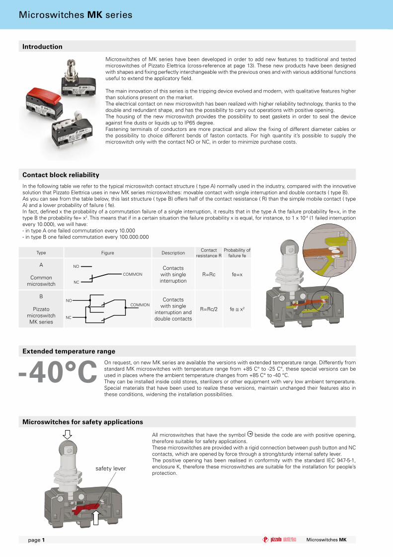
Microswitches for safety applications
All microswitches that have the symbol beside the code are with positive opening, therefore suitable for safety applications.These microswitches are provided with a rigid connection between push button and NC contacts, which are opened by force through a strong/sturdy internal safety lever.The positive opening has been realised in conformity with the standard IEC 947-5-1, enclosure K, therefore these microswitches are suitable for the installation for people’s protection.
Contact block reliability
In the following table we refer to the typical microswitch contact structure ( type A) normally used in the industry, compared with the innovative solution that Pizzato Elettrica uses in new MK series microswitches: movable contact with single interruption and double contacts ( type B).As you can see from the table below, this last structure ( type B) offers half of the contact resistance ( R) than the simple mobile contact ( type A) and a lower probability of failure ( fe).In fact, defined x the probability of a commutation failure of a single interruption, it results that in the type A the failure probability fe=x, in the type B the probability fe= x2. This means that if in a certain situation the failure probability x is equal, for instance, to 1 x 10⁻⁴ (1 failed interruption every 10.000), we will have:- in type A one failed commutation every 10.000- in type B one failed commutation every 100.000.000
Microswitches of MK series have been developed in order to add new features to traditional and tested microswitches of Pizzato Elettrica (cross-reference at page 13). These new products have been designed with shapes and fixing perfectly interchangeable with the previous ones and with various additional functions useful to extend the applicatory field.
The main innovation of this series is the tripping device evolved and modern, with qualitative features higher than solutions present on the market.The electrical contact on new microswitch has been realized with higher reliability technology, thanks to the double and redundant shape, and has the possibility to carry out operations with positive opening.The housing of the new microswitch provides the possibility to seat gaskets in order to seal the device against fine dusts or liquids up to IP65 degree.Fastening terminals of conductors are more practical and allow the fixing of different diameter cables or the possibility to choice different bends of faston contacts. For high quantity it’s possible to supply the microswitch only with the contact NO or NC, in order to minimize purchase costs.
Introduction
Extended temperature range
On request, on new MK series are available the versions with extended temperature range. Differently from standard MK microswitches with temperature range from +85 C° to -25 C°, these special versions can be used in places where the ambient temperature changes from +85 C° to -40 °C.They can be installed inside cold stores, sterilizers or other equipment with very low ambient temperature. Special materials that have been used to realize these versions, maintain unchanged their features also in these conditions, widening the installation possibilities.
Type Figure Description Contactresistance R
Probability of failure fe
A
Common microswitch
COMMON
NC
NO Contacts with single interruption
R=Rc fe=x
B
Pizzatomicroswitch MK series
NC
NOCOMMON
Contacts with single
interruption and double contacts
R=Rc/2 fe x2
safety lever
Microswitches MK series
Microswitches MK page 2
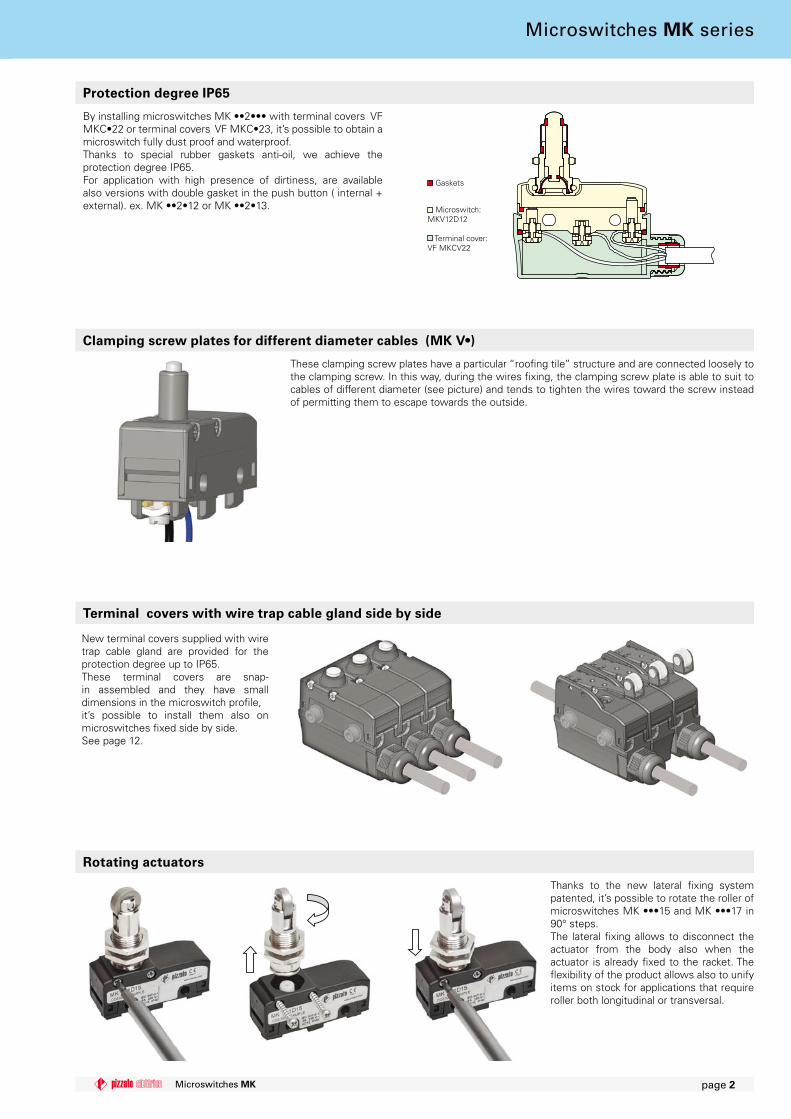
Rotating actuators
Thanks to the new lateral fixing system patented, it’s possible to rotate the roller of microswitches MK •••15 and MK •••17 in 90° steps.The lateral fixing allows to disconnect the actuator from the body also when the actuator is already fixed to the racket. The flexibility of the product allows also to unify items on stock for applications that require roller both longitudinal or transversal.
Protection degree IP65
By installing microswitches MK ••2••• with terminal covers VFMKC•22 or terminal covers VF MKC•23, it’s possible to obtain a microswitch fully dust proof and waterproof.Thanks to special rubber gaskets anti-oil, we achieve the protection degree IP65.For application with high presence of dirtiness, are available also versions with double gasket in the push button ( internal + external). ex. MK ••2•12 or MK ••2•13. Microswitch:
MKV12D12
Terminal cover:VF MKCV22
Clamping screw plates for different diameter cables (MK V•)
Terminal covers with wire trap cable gland side by side
These clamping screw plates have a particular “roofing tile” structure and are connected loosely to the clamping screw. In this way, during the wires fixing, the clamping screw plate is able to suit to cables of different diameter (see picture) and tends to tighten the wires toward the screw instead of permitting them to escape towards the outside.
New terminal covers supplied with wire trap cable gland are provided for the protection degree up to IP65.These terminal covers are snap-in assembled and they have small dimensions in the microswitch profile, it’s possible to install them also on microswitches fixed side by side.See page 12.
Gaskets
Microswitches MK series
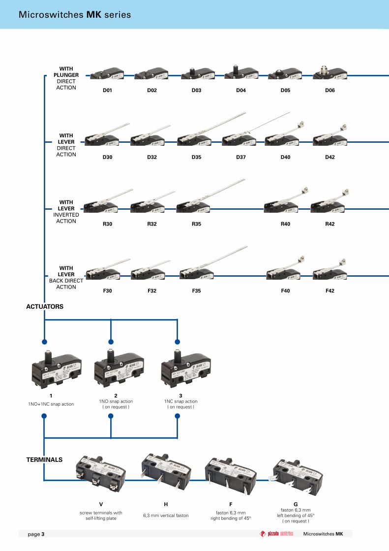
D0� D02 D03 D04 D05 D06
D30 D32 D35 D37 D40 D42
R30 R32 R35 R40 R42
F30 F32 F35 F40 F42
Microswitches MKpage 3
WITH PLUNGER
DIRECT ACTION
WITH LEVERDIRECT ACTION
WITH LEVER
INVERTED ACTION
WITHLEVER
BACK DIRECT ACTION
� 2 3
1NO+1NC snap action 1NO snap action( on request )
1NC snap action( on request )
ACTUATORS
TERMINALS
V H F G
screw terminals with self-lifting plate 6,3 mm vertical faston faston 6,3 mm
right bending of 45°
faston 6,3 mmleft bending of 45°
( on request )
Microswitches MK series
MK V�2D40-GR�6T6
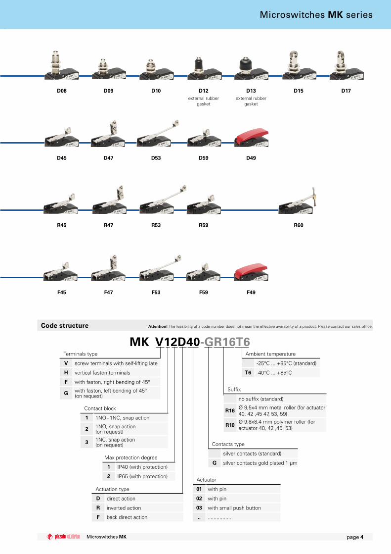
D45 D47 D53 D59 D49
R45 R47 R53 R59 R60
F45 F47 F53 F59 F49
D08 D09 D�0 D�2 D�3 D�5 D�7
Microswitches MK page 4
Code structure Attention! The feasibility of a code number does not mean the effective availability of a product. Please contact our sales office.
Contact block
� 1NO+1NC, snap action
2 1NO, snap action(on request)
3 1NC, snap action(on request)
Actuation type
D direct action
R inverted action
F back direct action
Max protection degree
� IP40 (with protection)
2 IP65 (with protection)
Suffix
no suffix (standard)
R�6 Ø 9,5x4 mm metal roller (for actuator 40, 42 ,45 47, 53, 59)
R�0Ø 9,8x8,4 mm polymer roller (for actuator 40, 42 ,45, 53)
Terminals type
V screw terminals with self-lifting late
H vertical faston terminals
F with faston, right bending of 45°
G with faston, left bending of 45°(on request)
Actuator
0� with pin
02 with pin
03 with small push button
.. ................
Contacts type
silver contacts (standard)
G silver contacts gold plated 1 µm
Ambient temperature
-25°C ... +85°C (standard)
T6 -40°C ... +85°C
external rubber gasket
external rubber gasket
Microswitches MK series
Microswitches MKpage 5
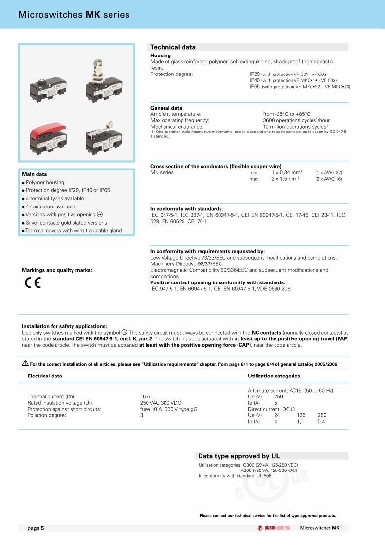
Technical data
In conformity with standards:IEC 947-5-1, IEC 337-1, EN 60947-5-1, CEI EN 60947-5-1, CEI 17-45, CEI 23-11, IEC 529, EN 60529, CEI 70-1
Cross section of the conductors (flexible copper wire)MK series: min. 1 x 0,34 mm2 (1 x AWG 22) max 2 x 1,5 mm2 (2 x AWG 16)
Main data
Polymer housing
Protection degree IP20, IP40 or IP65
4 terminal types available
47 actuators available
Versions with positive opening
Silver contacts gold plated versions
Terminal covers with wire trap cable gland
HousingMade of glass-reinforced polymer, self-extinguishing, shock-proof thermoplasticresin.Protection degree: IP20 (with protection VF C01 - VF C03) IP40 (with protection VF MKC•1• - VF C02) IP65 (with protection VF MKC•22 - VF MKC•23)
General dataAmbient temperature: from -25°C to +85°CMax operating frequency: 3600 operations cycles1/hourMechanical endurance: 10 million operations cycles1
(1) One operation cycle means two movements, one to close and one to open contacts, as foreseen by IEC 947-5-1 standard.
Thermal current (Ith): 16 ARated insulation voltage (Ui): 250 VAC 300 VDC
Protection against short circuits: fuse 10 A 500 V type gGPollution degree: 3
Markings and quality marks:
Electrical data Utilization categories
In conformity with requirements requested by: Low Voltage Directive 73/23/EEC and subsequent modifications and completions. Machinery Directive 98/37/EEC.Electromagnetic Compatibility 89/336/EEC and subsequent modifications and completions.Positive contact opening in conformity with standards:IEC 947-5-1, EN 60947-5-1, CEI EN 60947-5-1, VDE 0660-206.
For the correct installation of all articles, please see “Utilization requirements” chapter, from page 6/� to page 6/4 of general catalog 2005/2006
Installation for safety applications:Use only switches marked with the symbol . The safety circuit must always be connected with the NC contacts (normally closed contacts) as stated in the standard CEI EN 60947-5-�, encl. K, par. 2. The switch must be actuated with at least up to the positive opening travel (FAP) near the code article. The switch must be actuated at least with the positive opening force (CAP), near the code article.
Microswitches MK series
Please contact our technical service for the list of type approved products.
Data type approved by ULUtilization categories Q300 (69 VA, 125-250 VDC) A300 (720 VA, 120-300 VAC)In conformity with standard: UL 508
Alternate current: AC15 (50 ... 60 Hz)Ue (V) 250Ie (A) 5Direct current: DC13Ue (V) 24 125 250Ie (A) 4 1,1 0,4
9.7
8.5
6.3 12.7 12.7 6.3
12.2
1919
7 710.8
14.3
6.3 12.7 12.7 6.3
19 19
6.3
12
12.7 12.7 6.36.3
45°
19 19 6.4
6.3
12
6.3 12.7 12.7 6.3
45°
19 196.4
6.3
�2
3
Vmax (m/s)
Vmin(mm/s)
0,5 0,05
ϕ Vmax (m/s)
Vmin
(mm/s)
15° 0,6 0,2
30° 0,3 0,1
45° 0,1 0,05
L L L
L L
Vmax (m/s)
Vmin(mm/s)
0,03 x L 0,0166 x L
Vmax (m/s)
Vmin(mm/s)
0,015 x L 0,0083 x L
Vmax (m/s)
Vmin(mm/s)
0,01 x L 0,0047 x L
L
ϕ Vmax (m/s)
Vmin
(mm/s)
15° 0,1 x L 0,0664 x L
30° 0,05 x L 0,0332 x L
45° 0,03 x L 0,0166 x L
ϕ Vmax (m/s)
Vmin
(mm/s)
15° 0,048 x L 0,0332 x L
30° 0,024 x L 0,0166 x L
45° 0,015 x L 0,0083 x L
ϕ Vmax (m/s)
Vmin
(mm/s)
15° 0,032 x L 0,0188 x L
30° 0,016 x L 0,0094 x L
45° 0,01 x L 0,0047 x L
4
Microswitches MK page 6
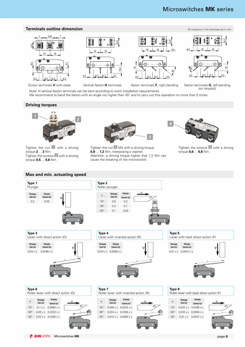
Max and min. actuating speed
Type 6Roller lever with direct action (D)
Type 7Roller lever with inverted action (R)
Type � Plunger
Type 2Roller plunger
Type 3 Lever with direct action (D)
Type 4Lever with inverted action (R)
Type 5Lever with back direct action (F)
Type 8Roller lever with back direct action (F)
Screw terminals V with plate Vertical faston H terminals faston terminals F, right bending faston terminals G, left bending(on request)
Note: H vertical faston terminals can be bent according to one’s installation requirements.We recommend to bend the faston with an angle not higher than 45° and to carry out this operation no more than 5 times.
Terminals outline dimension All measures in the drawings are in mm
Driving torques
Tighten the nut � with a driving torque 2 ... 3 Nm.Tighten the screws 2 with a driving torque 0,5 ... 0,6 Nm.
Tighten the nut 3 M4 with a driving torque 0,8 ... �,2 Nm, interposing a washer.Attention: a driving torque higher that 1,2 Nm can cause the breaking of the microswitch.
Tighten the screws 4 with a driving torque 0,6 ... 0,8 Nm.
Microswitches MK series
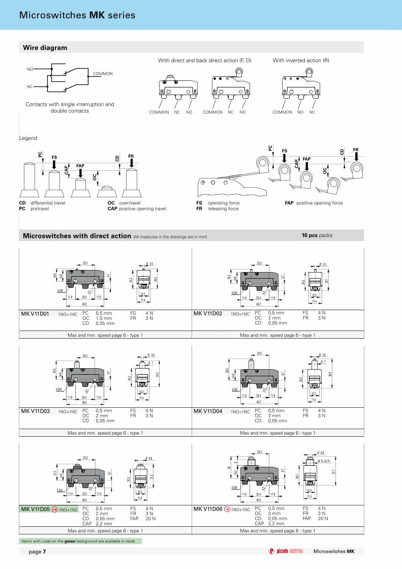
MK V11D01 1NO+1NC PCOCCD
0,5 mm1,5 mm0,05 mm
FSFR
4 N3 N
23.3
16.6
14.6
11.9 25.4 11.9
9.7
4.2
49.2
4.2x5
17.4
Ø 2.5
24.3 26.3
12.2
23.3
11.9 25.4 11.9
14.618
.4 9.7
49.2
4.24.2x512.2
17.4
28.1
24.3
Ø 2.5
MK V11D02 1NO+1NC PCOCCD
0,5 mm2 mm0,05 mm
FSFR
4 N3 N
11.925.411.9
23.3
14.624
.5
9.7
4.2
49.2
4.2x512.2
17.4
Ø 3.8
Ø 7
34.2
24.3
23.3
14.6
28.5
11.9 25.4 11.9
9.7
49.2
4.24.2x512.2
17.4
Ø 3.8
Ø 7
38.2
24.3
23.3
11.9 25.4 11.9
14.621
.5 9.7
49.2
4.24.2x5
17.4
Ø 6.8
12.2
31.2
24.3
25.411.9 11.9
23.3
28
16.4
8
9.7
4.2
49.2
4.2x5
Ø 6.8
M 10 x0.75
12.2
17.4
37.7
26.1
MK V11D03 1NO+1NC PCOCCD
0,5 mm2 mm0,05 mm
FSFR
4 N3 N
MK V11D04 1NO+1NC PCOCCD
0,5 mm2 mm0,05 mm
FSFR
4 N3 N
MK V11D05 1NO+1NC PCOCCDCAP
0,5 mm2 mm0,05 mm2,2 mm
FSFRFAP
4 N3 N20 N
MK V11D06 1NO+1NC PCOCCDCAP
0,5 mm3 mm0,05 mm2,2 mm
FSFRFAP
4 N3 N20 N
PC
CA
P
OC
CDFS FR
FAP
PC
CA
P
OC
CDFS FR
FAP
NC
NOCOMMON
COMMON NC NO COMMON NO NCCOMMON NC NO
Microswitches MKpage 7
Items with code on the green background are available in stock
Max and min. speed page 6 - type 1 Max and min. speed page 6 - type 1
Max and min. speed page 6 - type 1 Max and min. speed page 6 - type 1
Max and min. speed page 6 - type 1 Max and min. speed page 6 - type 1
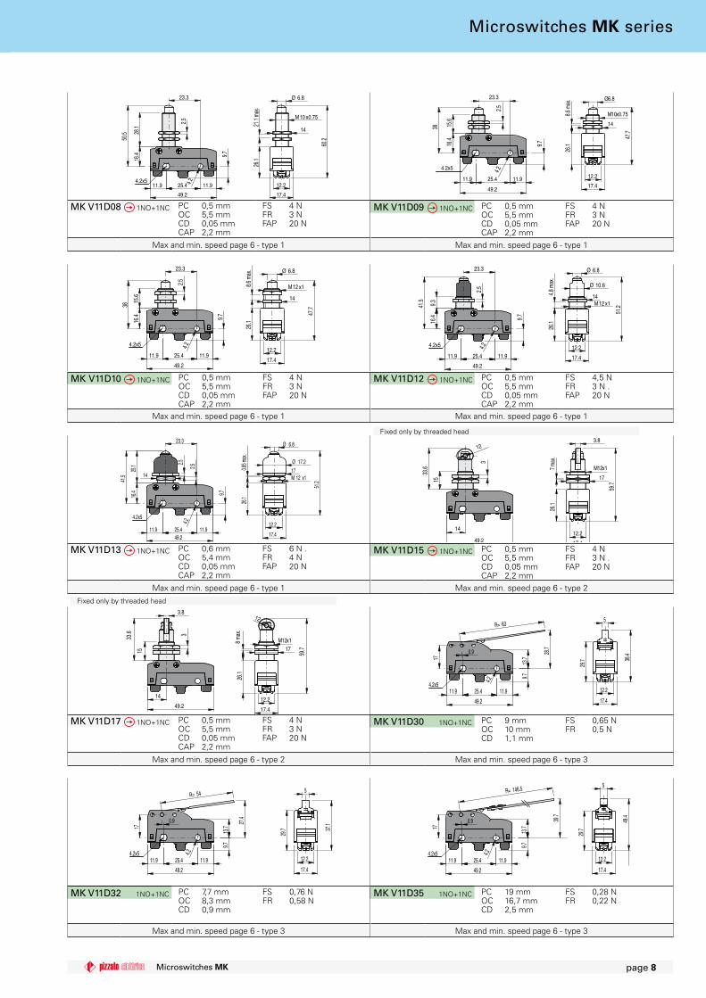
Microswitches with direct action (All measures in the drawings are in mm)
CD differential travelPC pretravel
OC over-travelCAP positive opening travel
FS operating forceFR releasing force
FAP positive opening force
�0 pcs packs
Legend
Microswitches MK series
Wire diagram
Contacts with single interruption and double contacts
With direct and back direct action (F, D) With inverted action (R)
11.9 25.4 11.9
23.3
16.4
50.5
9.7
28.1
2.54.2
49.2
4.2x512.2
17.4
60.2
Ø 6.8
M10 x0.75
26.1
14
21.1
max.
11.9 25.4 11.9
16.4
38
23.3
15.6
9.7
49.2
4.22.5
4.2x512.2
17.4
M10x0.75
14
8.6 m
ax.
26.1
47.7
Ø6.8
MK V11D08 1NO+1NC PCOCCDCAP
0,5 mm5,5 mm0,05 mm2,2 mm
FSFRFAP
4 N3 N20 N
MK V11D09 1NO+1NC PCOCCDCAP
0,5 mm5,5 mm0,05 mm2,2 mm
FSFRFAP
4 N3 N20 N
MK V11D13 1NO+1NC PCOCCDCAP
0,6 mm5,4 mm0,05 mm2,2 mm
FSFRFAP
6 N .4 N20 N
11.9 25.4 11.9
16.4
41.5
23.3
9.7
25.1
49.2
4.22.5
2.5
14
4.2x5
17.4
12.2
17
51.2
26.1
0.85 m
ax.
Ø 6.8
Ø 17.2
M 12 x1
14
3
12
15
49.2
33.6
12.2
17.4
59.7
17
M12x17 max
.26
.1
3.8
MK V11D15 1NO+1NC PCOCCDCAP
0,5 mm5,5 mm0,05 mm2,2 mm
FSFRFAP
4 N3 N .20 N
14
3
3.8
49.2
15
33.6
12
12.2
17.4
17
26.1
8 max
.
59.7
M12x1
11.9 25.4 11.9
13.717
0.9 28.7
9.7
49.2
4.2
R= 63
4.2x512.2
17.4
38.4
29.7
5
11.9 25.4 11.9
13.717
0.9 27.4
9.7
49.2
4.2
R= 54
4.2x512.2
17.4
37.1
29.7
5
11.9 25.4 11.9
13.717
0.9 39.7
9.7
49.2
4.2
R= 146.5
4.2x512.2
17.4
29.7
5
49.4
MK V11D17 1NO+1NC PCOCCDCAP
0,5 mm5,5 mm0,05 mm2,2 mm
FSFRFAP
4 N3 N20 N
MK V11D30 1NO+1NC PCOCCD
9 mm10 mm1,1 mm
FSFR
0,65 N0,5 N
MK V11D32 1NO+1NC PCOCCD
7,7 mm8,3 mm0,9 mm
FSFR
0,76 N0,58 N
MK V11D35 1NO+1NC PCOCCD
19 mm16,7 mm2,5 mm
FSFR
0,28 N0,22 N
11.9 25.4 11.9
23.3
16.4
38
9.7
2.5
15.6
49.2
4.24.2x5
26.1
47.7
12.2
17.4
14
8.6 m
ax. Ø 6.8
M12 x1
11.9 25.4 11.9
16.4
9.341.5
23.3
9.7
49.2
2.54.24.2x5 12.2
17.4
26.1
14M12 x1
51.2
4.8 m
ax.
Ø 6.8
Ø 10.6
MK V11D12 1NO+1NC PCOCCDCAP
0,5 mm5,5 mm0,05 mm2,2 mm
FSFRFAP
4,5 N3 N .20 N
MK V11D10 1NO+1NC PCOCCDCAP
0,5 mm5,5 mm0,05 mm2,2 mm
FSFRFAP
4 N3 N20 N
Microswitches MK page 8
Max and min. speed page 6 - type 1 Max and min. speed page 6 - type 2
Max and min. speed page 6 - type 2 Max and min. speed page 6 - type 3
Max and min. speed page 6 - type 3 Max and min. speed page 6 - type 3
Max and min. speed page 6 - type 1 Max and min. speed page 6 - type 1
Max and min. speed page 6 - type 1 Max and min. speed page 6 - type 1
Fixed only by threaded head
Fixed only by threaded head
Microswitches MK series
25.4
17
0.9
11.9 11.9
13.7
45.4
9.7
R= 24.6
4.2
49.2
9.5
4.2x512.2
4.2
17.4
29.7
55.1
11.9 25.4 11.9
13.717
26.10.9
9.7
49.2
4.24.2x5 12.2
17.4
35.8
16.6
29.7
R= 38.2
25.4
17
0.9
13.7
11.9 11.9
9.7
38.4
R= 54
4.2
9.5
49.2
4.2x512.2
4.2
48.1
29.7
25.4
17
0.9
11.9 11.9
13.7
R= 17.8
9.7
33.2
4.2
49.2
9.5
4.2x512.2
4.2
17.4
29.7 42
.9
25.4
17
0.9
11.9 11.9
13.7
R= 37.5
9.7
36
4.2
49.2
9.5
4.2x512.2
4.2
17.4
29.7
45.7
11.925.411.9
17
34.2
0.9
13.7
9.7
R= 24.6 9.5
4.2
49.2
4.2x5
17.4
12.2
4.2
43.9
29.7
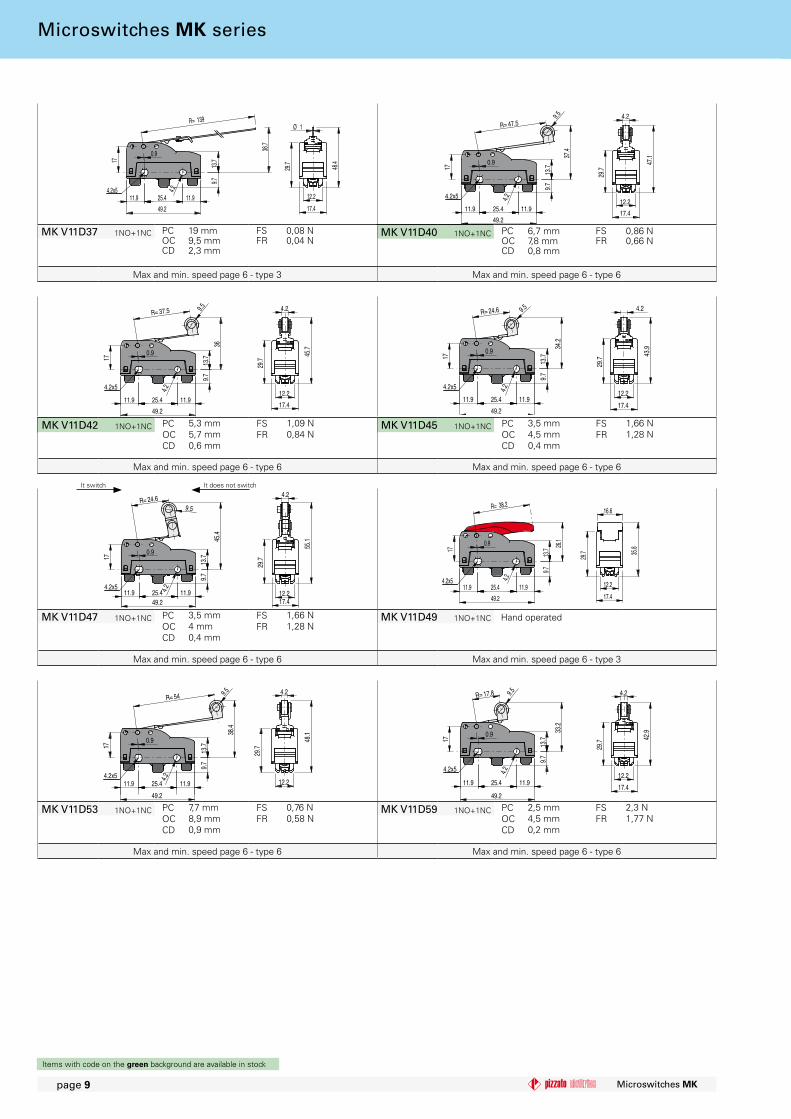
MK V11D42 1NO+1NC PCOCCD
5,3 mm5,7 mm0,6 mm
FSFR
1,09 N0,84 N
MK V11D45 1NO+1NC PCOCCD
3,5 mm4,5 mm0,4 mm
FSFR
1,66 N1,28 N
MK V11D47 1NO+1NC PCOCCD
3,5 mm4 mm0,4 mm
FSFR
1,66 N1,28 N
MK V11D49 1NO+1NC Per azionamento manuale
MK V11D53 1NO+1NC PCOCCD
7,7 mm8,9 mm0,9 mm
FSFR
0,76 N0,58 N
MK V11D59 1NO+1NC PCOCCD
2,5 mm4,5 mm0,2 mm
FSFR
2,3 N1,77 N
11.9 25.4 11.9
13.717
0.9
9.7
38.7
49.2
4.2
R= 139
4.2x512.2
17.4
29.7
Ø 1
48.4
25.4
17
0.9
11.9 11.9
13.7
R= 47.5
9.7
37.4
4.2
49.2
9.5
4.2x512.2
4.2
17.4
29.7
47.1
MK V11D37 1NO+1NC PCOCCD
19 mm9,5 mm2,3 mm
FSFR
0,08 N0,04 N
MK V11D40 1NO+1NC PCOCCD
6,7 mm7,8 mm0,8 mm
FSFR
0,86 N0,66 N
Microswitches MKpage 9
Items with code on the green background are available in stock
Max and min. speed page 6 - type 6 Max and min. speed page 6 - type 3
Max and min. speed page 6 - type 6 Max and min. speed page 6 - type 6
Max and min. speed page 6 - type 6 Max and min. speed page 6 - type 6
It switch It does not switch
Hand operated
Microswitches MK series
Max and min. speed page 6 - type 3 Max and min. speed page 6 - type 6
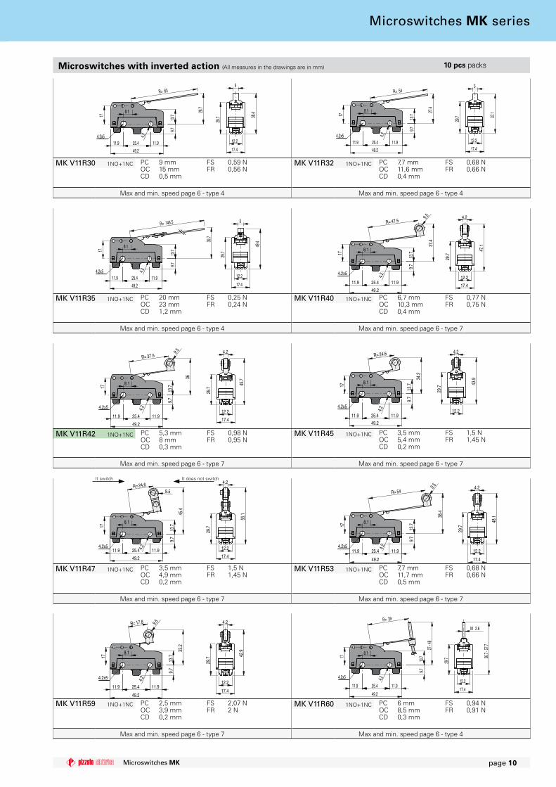
MK V11R30 1NO+1NC PCOCCD
9 mm15 mm0,5 mm
FSFR
0,59 N0,56 N
MK V11R32 1NO+1NC PCOCCD
7,7 mm11,6 mm0,4 mm
FSFR
0,68 N0,66 N
MK V11R35 1NO+1NC PCOCCD
20 mm23 mm1,2 mm
FSFR
0,25 N0,24 N
MK V11R40 1NO+1NC PCOCCD
6,7 mm10,3 mm0,4 mm
FSFR
0,77 N0,75 N
MK V11R42 1NO+1NC PCOCCD
5,3 mm8 mm0,3 mm
FSFR
0,98 N0,95 N
MK V11R45 1NO+1NC PCOCCD
3,5 mm5,4 mm0,2 mm
FSFR
1,5 N1,45 N
MK V11R47 1NO+1NC PCOCCD
3,5 mm4,9 mm0,2 mm
FSFR
1,5 N1,45 N
MK V11R53 1NO+1NC PCOCCD
7,7 mm11,7 mm0,5 mm
FSFR
0,68 N0,66 N
MK V11R59 1NO+1NC PCOCCD
2,5 mm3,9 mm0,2 mm
FSFR
2,07 N2 N
MK V11R60 1NO+1NC PCOCCD
6 mm8,5 mm0,3 mm
FSFR
0,94 N0,91 N
11.9 25.4 11.9
13.7
28.7
9.7
17
8.1
49.2
4.2
R= 63
4.2x512.2
17.4
38.4
29.7
5
11.9 25.4 11.9
13.7
27.4
9.7
17
8.1
49.2
4.2
R= 54
4.2x512.2
17.4
37.1
29.7
5
11.9 25.4 11.9
13.7
9.7
17
8.1
39.7
49.2
4.2
R= 146.5
4.2x512.2
17.4
29.7
5
49.4
25.411.9 11.9
13.7
9.7
8.1
17
37.4
R= 47.5
4.2
49.2
9.5
4.2x512.2
4.2
17.4
29.7
47.1
25.411.9 11.9
13.7
9.7
36
8.1
17
R= 37.5
4.2
49.2
9.5
4.2x512.2
4.2
17.4
29.7
45.7
25.49.
7
8.1
17
11.9 11.913
.7
34.2
R= 24.6
4.2
49.2
4.2x512.2
43.9
29.7
4.2
25.411.9 11.9
13.7
45.4
9.7
8.1
17
R= 24.6
4.2
49.2
9.5
4.2x5 12.2
4.2
17.4
29.7
55.1
25.4
9.7
8.1
17
13.7
38.4
11.911.9
R= 54
4.2
9.5
49.2
4.2x512.2
17.4
48.1
4.2
29.7
25.411.9 11.9
13.7
9.7
33.2
17
8.1
R= 17.8
4.2
49.2
9.5
4.2x512.2
4.2
17.4
29.7 42
.9
25.411.9 11.9
13.7
27 - 4
8
9.7
8.1
17
R= 39
4.2
49.2
4.2x512.2
17.4
29.7
M 2.6
36.7
- 57.7
Microswitches MK page �0
It switch It does not switch
Max and min. speed page 6 - type 4
Microswitches with inverted action (All measures in the drawings are in mm) �0 pcs packs
Max and min. speed page 6 - type 4
Max and min. speed page 6 - type 4 Max and min. speed page 6 - type 7
Max and min. speed page 6 - type 7
Max and min. speed page 6 - type 7 Max and min. speed page 6 - type 4
Max and min. speed page 6 - type 7
Max and min. speed page 6 - type 7
Max and min. speed page 6 - type 7
Microswitches MK series
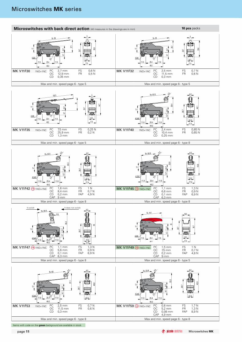
MK V11F30 1NO+1NC PCOCCD
2,7 mm12,9 mm0,35 mm
FSFR
0,6 N 0,5 N
MK V11F32 1NO+1NC PCOCCD
2,5 mm11,5 mm0,3 mm
FSFR
0,7 N0,6 N
MK V11F35 1NO+1NC PCOCCD
7,5 mm25,9 mm1,3 mm
FSFR
0,25 N0,2 N
MK V11F40 1NO+1NC PCOCCD
2,4 mm10,4 mm0,25 mm
FSFR
0,85 N0,65 N
MK V11F42 1NO+1NC PCOCCDCAP
1,6 mm8,4 mm0,2 mm9 mm
FSFRFAP
1 N0,7 N4,9 N
MK V11F45 1NO+1NC PCOCCDCAP
1,1 mm6,6 mm0,1 mm6,3 mm
FSFRFAP
1,3 N0,9 N6,9 N
MK V11F47 1NO+1NC PCOCCDCAP
1,1 mm5,6 mm0,1 mm6,3 mm
FSFRFAP
1,3 N0,9 N6,9 N
MK V11F53 1NO+1NC PCOCCD
2,5 mm11,5 mm0,3 mm
FSFR
0,7 N0,6 N
MK V11F59 1NO+1NC PCOCCDCAP
0,8 mm5,2 mm0,08 mm4,9 mm
FSFRFAP
1,7 N1,3 N8,9 N
MK V11F49 1NO+1NC PCOCCDCAP
1,5 mm7,5 mm0,2 mm9 mm
FSFRFAP
1 N0,7 N4,8 N
25.411.9 11.913
.717
8.4 27.1
9.7
4.2
49.2
R= 69
4.2x512.2
17.4
5
29.7 36
.8
25.4
17
8.4 26.1
13.7
11.911.9
9.7
4.2
49.2
R= 60
4.2x512.2
17.4
5
29.7 35
.8
11.9 25.4 11.9
13.7
9.7
35
8.4
17
49.2
4.2
152.5
4.2x512.2
17.4
29.7
5
44.7
25.411.9 11.9
13.717
R= 53.5
8.4
9.7
36.4
4.2
49.2
9.5
4.2x512.2
4.2
17.4
29.7
46.1
25.411.9 11.9
13.717
8.4
35.3
R= 43.5
9.7
4.2
49.2
9.5
4.2x512.2
4.2
17.4
29.7
45
25.4
9.7
13.7
11.911.9
33.9
17
8.4
R= 30.64.2
9.5
49.2
4.2x512.2
17.4
4.2
43.6
25.411.9 11.9
13.7
45.3
9.7
17
8.4
R= 30.6
4.2
49.2
9.5
4.2x512.2
4.2
17.4
29.7
55
25.4
9.7
11.911.9
17
13.7
268.4
4.2
49.2
4.2x5 12.2
17.4
16.6
35.7
29.7
R= 44.1
25.4
13.7
11.9 11.9
9.7
37.1
R= 60
8.4
17
4.2
9.5
49.2
4.2x512.2
4.2
46.8
29.7
25.4
13.7
11.9 11.9
9.7
33.2
8.4
17
R= 23.8
4.29.5
49.2
4.2x512.2
4.2
42.9
29.7
Microswitches MKpage ��
Items with code on the green background are available in stock
Microswitches with back direct action (All measures in the drawings are in mm) �0 pcs packs
Max and min. speed page 6 - type 5 Max and min. speed page 6 - type 5
Max and min. speed page 6 - type 5 Max and min. speed page 6 - type 8
Max and min. speed page 6 - type 8 Max and min. speed page 6 - type 8
Max and min. speed page 6 - type 8
Max and min. speed page 6 - type 8
Max and min. speed page 6 - type 8
Max and min. speed page 6 - type 5
It switch It does not switch
Microswitches MK series
52.4
18.5 25
.1
65.4
13
9
16
8.2
17.4
65.4
13
32 38.6
52.4
9
16
17.4
8.2
25.4
5 4.3 21.1 4.3
17
20.8
8
52.8
8 2222
8 10
54 10.5
4.3 4.34.5
25
25.4
Ø 20
68.3
22
54
10 8 15.3 8 10
912.2
18.7
17.2
51.3
8
14
M10x 0.75 2.5
14
M12 x12.5
Microswitches MK page �2
Items with code on the green background are available in stock
Accessories
Article Description
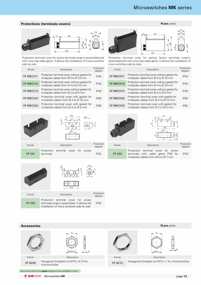
VF AC83 Hexagonal threaded nut M10 x 0,75 for microswitches
Article Description
VF AC72 Hexagonal threaded nut M12 x 1 for microswitches
Article Description Protection degree
VF C01Protection terminal cover for screw terminals IP20
Article Description Protection degree
VF C02Protection terminal cover for screw terminals with cable gland PG9 for multipolar cables from Ø 5 to Ø 7 mm
IP40
Article Description Protection degree
VF C03Protection terminal cover for screw terminals snap-in assembled. It allows the installation of more switches side by side
IP20
Protection terminal cover for screw terminals snap-in assembled and with wire trap cable gland. It allows the installation of more switches side by side.
Article Description Protection degree
VF MKCV11 Protection terminal cover without gasket for multipolar cables from Ø 5 to Ø 7,5 mm IP40
VF MKCV12 Protection terminal cover without gasket for multipolar cables from Ø 4 to Ø 7,5 mm IP40
VF MKCV13 Protection terminal cover without gasket for multipolar cables from Ø 2 to Ø 5 mm IP40
VF MKCV22 Protection terminal cover with gasket for multipolar cables from Ø 4 to Ø 7,5 mm IP65
VF MKCV23 Protection terminal cover with gasket for multipolar cables from Ø 2 to Ø 5 mm IP65
Protections (terminals covers) �0 pcs packs
Protection terminal cover for vertical faston terminals snap-in assembled and with wire trap cable gland. It allows the installation of more switches side by side.
Article Description Protection degree
VF MKCH11 Protection terminal cover without gasket for multipolar cables from Ø 5 to Ø 7,5 mm IP40
VF MKCH12 Protection terminal cover without gasket for multipolar cables from Ø 4 to Ø 7,5 mm IP40
VF MKCH13 Protection terminal cover without gasket for multipolar cables from Ø 2 to Ø 5 mm IP40
VF MKCH22 Protection terminal cover with gasket for multipolar cables from Ø 4 to Ø 7,5 mm IP65
VF MKCH23 Protection terminal cover with gasket for multipolar cables from Ø 2 to Ø 5 mm IP65
�0 pcs packs
Microswitches MK series
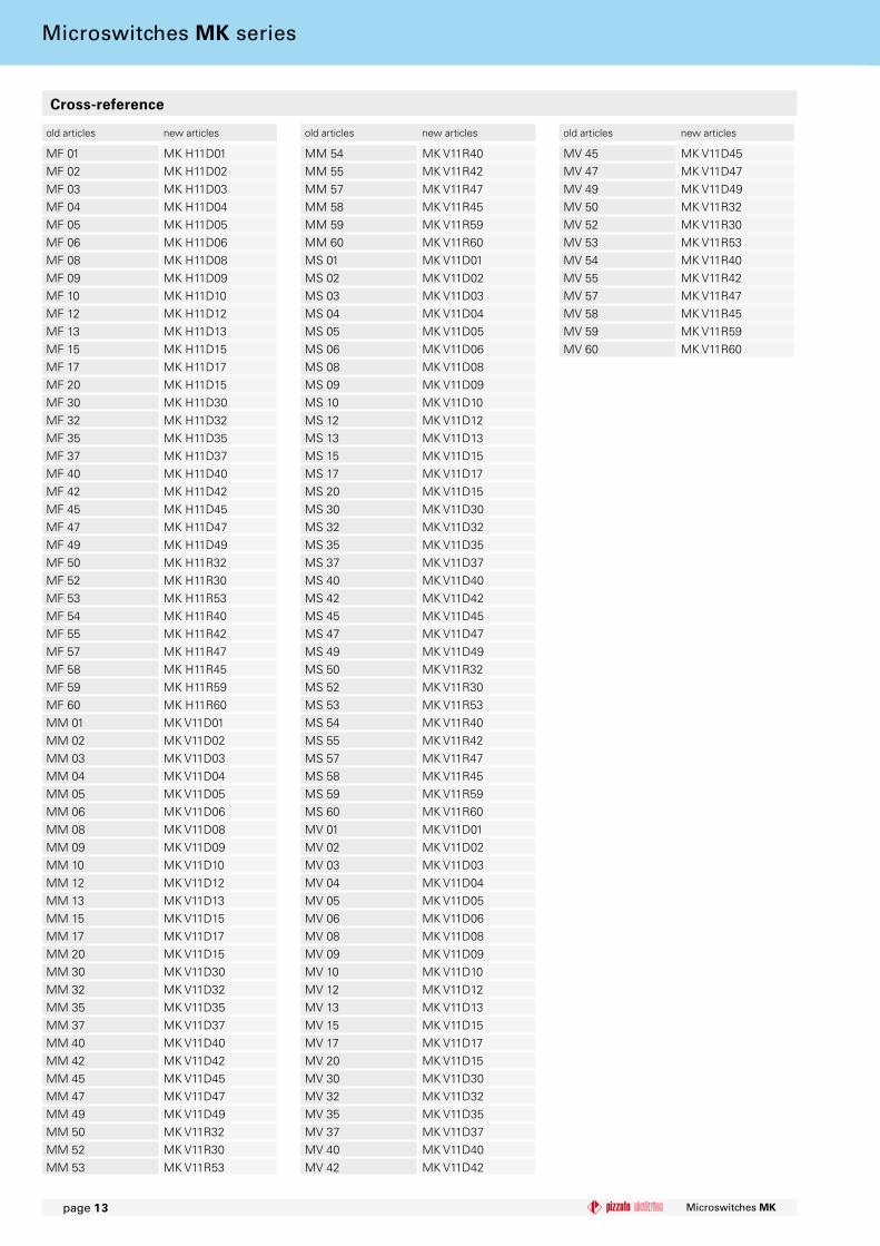
MF 01 MK H11D01MF 02 MK H11D02MF 03 MK H11D03MF 04 MK H11D04MF 05 MK H11D05MF 06 MK H11D06MF 08 MK H11D08MF 09 MK H11D09MF 10 MK H11D10MF 12 MK H11D12MF 13 MK H11D13MF 15 MK H11D15MF 17 MK H11D17MF 20 MK H11D15MF 30 MK H11D30MF 32 MK H11D32MF 35 MK H11D35MF 37 MK H11D37MF 40 MK H11D40MF 42 MK H11D42MF 45 MK H11D45MF 47 MK H11D47MF 49 MK H11D49MF 50 MK H11R32MF 52 MK H11R30MF 53 MK H11R53MF 54 MK H11R40MF 55 MK H11R42MF 57 MK H11R47MF 58 MK H11R45MF 59 MK H11R59MF 60 MK H11R60MM 01 MK V11D01MM 02 MK V11D02MM 03 MK V11D03MM 04 MK V11D04MM 05 MK V11D05MM 06 MK V11D06MM 08 MK V11D08MM 09 MK V11D09MM 10 MK V11D10MM 12 MK V11D12MM 13 MK V11D13MM 15 MK V11D15MM 17 MK V11D17MM 20 MK V11D15MM 30 MK V11D30MM 32 MK V11D32MM 35 MK V11D35MM 37 MK V11D37MM 40 MK V11D40MM 42 MK V11D42MM 45 MK V11D45MM 47 MK V11D47MM 49 MK V11D49MM 50 MK V11R32MM 52 MK V11R30MM 53 MK V11R53
MM 54 MK V11R40MM 55 MK V11R42MM 57 MK V11R47MM 58 MK V11R45MM 59 MK V11R59MM 60 MK V11R60MS 01 MK V11D01MS 02 MK V11D02MS 03 MK V11D03MS 04 MK V11D04MS 05 MK V11D05MS 06 MK V11D06MS 08 MK V11D08MS 09 MK V11D09MS 10 MK V11D10MS 12 MK V11D12MS 13 MK V11D13MS 15 MK V11D15MS 17 MK V11D17MS 20 MK V11D15MS 30 MK V11D30MS 32 MK V11D32MS 35 MK V11D35MS 37 MK V11D37MS 40 MK V11D40MS 42 MK V11D42MS 45 MK V11D45MS 47 MK V11D47MS 49 MK V11D49MS 50 MK V11R32MS 52 MK V11R30MS 53 MK V11R53MS 54 MK V11R40MS 55 MK V11R42MS 57 MK V11R47MS 58 MK V11R45MS 59 MK V11R59MS 60 MK V11R60MV 01 MK V11D01MV 02 MK V11D02MV 03 MK V11D03MV 04 MK V11D04MV 05 MK V11D05MV 06 MK V11D06MV 08 MK V11D08MV 09 MK V11D09MV 10 MK V11D10MV 12 MK V11D12MV 13 MK V11D13MV 15 MK V11D15MV 17 MK V11D17MV 20 MK V11D15MV 30 MK V11D30MV 32 MK V11D32MV 35 MK V11D35MV 37 MK V11D37MV 40 MK V11D40MV 42 MK V11D42
MV 45 MK V11D45MV 47 MK V11D47MV 49 MK V11D49MV 50 MK V11R32MV 52 MK V11R30MV 53 MK V11R53MV 54 MK V11R40MV 55 MK V11R42MV 57 MK V11R47MV 58 MK V11R45MV 59 MK V11R59MV 60 MK V11R60
Microswitches MKpage �3
old articles new articles old articles new articles old articles new articles
Cross-reference
Microswitches MK series
| | | | | | |
Microswitches MK page �4
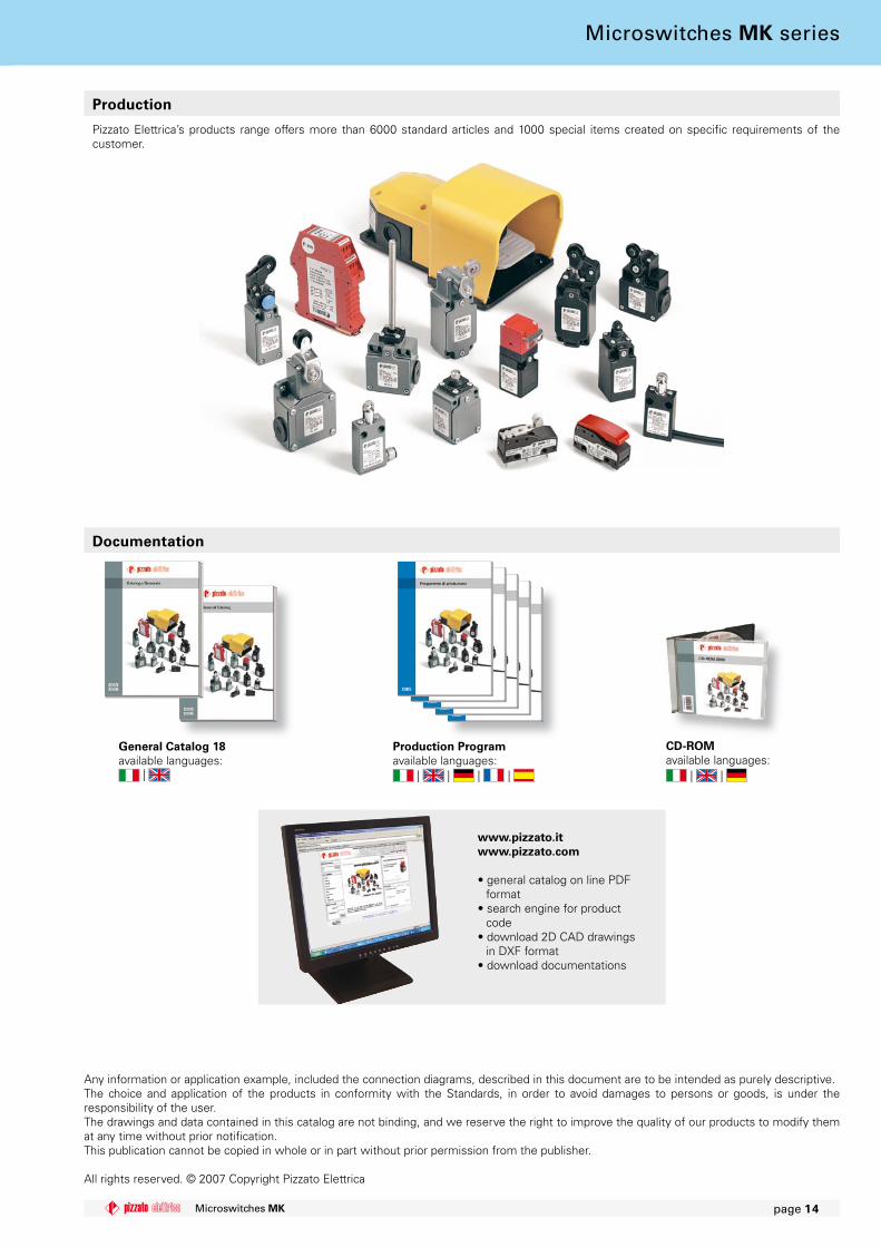
Pizzato Elettrica’s products range offers more than 6000 standard articles and 1000 special items created on specifi c requirements of the customer.
Production
www.pizzato.itwww.pizzato.com
• general catalog on line PDF format
• search engine for product code
• download 2D CAD drawings in DXF format
• download documentations
Documentation
Any information or application example, included the connection diagrams, described in this document are to be intended as purely descriptive.The choice and application of the products in conformity with the Standards, in order to avoid damages to persons or goods, is under the responsibility of the user.The drawings and data contained in this catalog are not binding, and we reserve the right to improve the quality of our products to modify them at any time without prior notifi cation.This publication cannot be copied in whole or in part without prior permission from the publisher.
All rights reserved. © 2007 Copyright Pizzato Elettrica
General Catalog �8available languages:
CD-ROMavailable languages:
Production Program available languages:
Microswitches MK series
Passion for Quality
© 2007 Copyright Pizzato Elettrica
Pizzato Elettrica s.r.l. Via Torino, 1 - 36063 Marostica (VI) ItalyPhone +39.0424.470.930 - Fax +39.0424.470.955
E-mail: [email protected] - Web site: www.pizzato.com
ZE BRC05B07-ENG
General catalog 2005/2006
Production program ATEX brochure Lift devices brochure
Cd-rom2006
Web sitewww.pizzato.com


![TME-DC [ ] - Sew Many Parts, Inc. of Contents z TME-DC GENERAL VIEW z TME-DC FRAME … CD-1 z TME-DC TABLE … CD-2-1 z TME-DC AUTO SUB TABLE …](https://static.documents.pub/doc/80x56/5b1d28797f8b9add7f8b64eb/tme-dc-sew-many-parts-inc-of-contents-z-tme-dc-general-view-z-tme-dc-frame.jpg)
