1 246098 MICROWAVE ENHANCED CRACKING OF ETHANE FOR ETHYLENE PRODUCTION Morgana Fall Operations Engineer Ceralink Inc. Eric Wagner Director Technology Development Technip Frank Cabe Technician Ceralink Inc. Gary Eagleson Senior Process Engineer Technip James Carnahan Chief Scientist Edison Laboratories Ravi Lal Commercial Vice President, Ethylene Technip Holly Shulman Materials Scientist Ceralink Inc. Prepared for Presentation at the 2012 Spring National Meeting Houston, Texas, April 3, 2012 AIChE and EPC shall not be responsible for statements or opinions contained in papers or printed in its publications
Transcript
1
246098
MICROWAVE ENHANCED CRACKING OF ETHANE FOR ETHYLENE PRODUCTION
Morgana Fall Operations Engineer
Ceralink Inc.
Eric Wagner Director Technology Development
Technip
Frank Cabe Technician
Ceralink Inc.
Gary Eagleson Senior Process Engineer
Technip
James Carnahan Chief Scientist
Edison Laboratories
Ravi Lal Commercial Vice President, Ethylene
Technip
Holly Shulman Materials Scientist
Ceralink Inc.
Prepared for Presentation at the 2012 Spring National Meeting Houston, Texas, April 3, 2012
AIChE and EPC shall not be responsible for statements or opinions contained in papers or printed in its publications
2
Microwave Enhanced Cracking of Ethane for Ethylene Production.
Morgana Fall
Operations Engineer Ceralink Inc. Eric Wagner
Director Technology Development Technip
Frank Cabe Technician
Ceralink Inc. Gary Eagleson
Senior Process Engineer Tecnhnip
James Carnahan Chief Scientist
Edison Laboratories Ravi Lal
Commercial Vice President, Ethylene Technip
Holly Shulman Materials Scientist
Ceralink Inc. Abstract: A laboratory-scale microwave cracking system was built and tested to explore the feasibility of direct hydrocarbon cracking from ethane. The microwave system operated at 2.45 GHz in a single mode microwave applicator. The gas stream was a mixture of ethane and argon, which was introduced into the microwave zone through a quartz tube reactor. Samples were collected from the product stream exiting the hot zone and analyzed using a gas chromatograph. Results indicated that it was possible to crack ethane and obtain ethylene with high product conversion and high ethylene selectivity. The results of the gas chromatographic analysis for several different run parameters are presented. The yields from the microwave reactor were consistent with results predicted by SPYRO® in a theoretical reactor operating under similar conditions of temperature and residence time. These initial results indicate there may be advantages of microwave heat transfer compared to conventional combustion furnaces. This may allow novel reactor designs that result in more efficient production of ethylene.
3
Summary
The overall objective of this work was to explore microwave heating as a method to significantly decrease the energy consumed during the cracking of hydrocarbons to form ethylene. This first step was to determine feasibility and explore different laboratory scale process configurations for producing ethylene. Ceralink Inc. (company specializing in commercializing energy efficient manufacturing technologies), and Technip (a world leader in ethylene production systems and project management) collaborated to investigate the hydrocarbon-microwave interaction mechanisms through microwave experiments on the cracking of ethane and comparing the laboratory results to conventional modeling. Ceralink designed, built and performed laboratory heating studies using a single mode microwave reactor operating at 2.45 GHz. Technip participated in the test program and performed modeling work using SPYRO® to predict ethane conversion rates and product yields.
This work demonstrated that a microwave heating system could be used to produce ethylene from ethane. A series of experiments were conducted which varied microwave power, system pressure, and flow rates to explore ethane conversion and product selectivity. A gas chromatograph was used to identify and quantify the product species, which included hydrogen, methane, acetylene, and ethylene. Initial results demonstrated this heat transfer method to be feasible, and indicated that ethylene yield and selectivity were similar to results modeled with SPYRO®. This suggests that microwaves neither enhance nor inhibit the pyrolysis chemistry.
Background
Ethylene and other olefins are produced from hydrocarbon materials and dilution steam fed into furnaces that require large amounts of fuel. The gaseous fuel is burned to produce the temperatures required to drive the cracking reactions, usually in excess of 850 °C. In the cracking furnace, the heat is transferred from the combustion products to the reactor coils via radiant and convective heat transfer. Since this conventional heat transfer approach requires a substantial temperature driving force, less than half the energy released from the combustion of the fuel is actually transferred directly to the furnace coils that contain the hydrocarbons. The balance of the fired energy is recovered for feed preheating and steam production.
In conventional heating, all heat must be transferred through the outer surface of the material to the interior. Microwave heating offers an important advantage of being able to place energy directly into the work piece. Microwave heating of materials occurs through internal friction when dielectric loss mechanisms respond in a microwave field. There are many loss mechanisms that can be activated in real materials related to crystal structure, defects, bonding, surface, grain boundaries, etc. In practical terms, microwave energy can be used to directly and rapidly heat materials. There are certain frequencies that are allowed for industrial
4
use, referred to as ISM (industrial, scientific and medical). The two most commonly used frequencies in industry are 915 MHz and 2.45 GHz.
Procedure
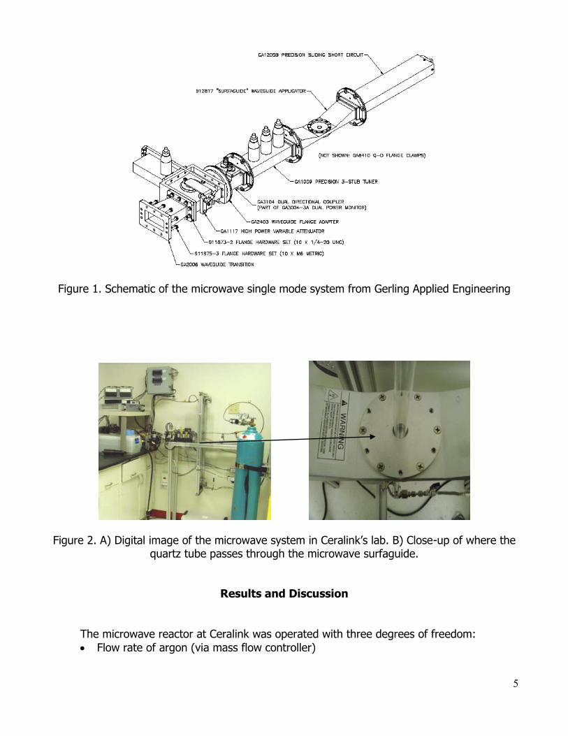
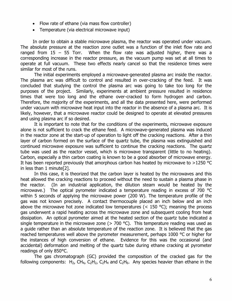
The laboratory scale microwave cracking system is shown in Figure 2. A single mode microwave system operating at 2.45 GHz with 2 kW available power was used. A surfaguide microwave applicator[1] specially designed for plasma was used to intensify the microwave field where the quartz tube passed through. The system also had a directional coupler for measuring the forward and reverse microwave power, along with a 3 stub tuner for impedance matching, and a variable attenuator for fine power adjustment.
This system used ethane as the hydrocarbon feedstock, and argon as the carrier gas. The flow rate for each gas was independently controlled using Brooks mass flow controllers (MFC). The gases passed through a static mixer prior to entering the quartz reaction tube. The flow rate of the MFCs were controlled and recorded using LabVIEW software, a computer graphical user interface for instrumentation. LabVIEW was also used to monitor and record inlet gas temperature, outlet gas temperature, pressure inside the system along with the microwave power and cooling water temperature. As a safety feature, an emergency stop button is located in the LabVIEW interface, which immediately shuts off the hydrocarbon gas flow and microwave energy. A Lexan safety shield is located in front of the hot zone of the quartz tube, which also incorporated microwave shielding. Microwave power was applied between 100 and 800 watts. The gas chromatograph (GC), model HP 5890A, was fitted with a thermal conductivity detector (TCD) and used argon as carrier gas. The GC was used for analysis of the hydrocarbon products during the laboratory testing and provided the composition of the cracked gas for the following components: H2, CH4, C2H2, C2H4 and C2H6. Any species heavier than ethane in the effluent would not be detected. The GC was located next to the microwave cracking system so that samples could be taken directly from the exhaust line of the reactor tube and introduced into the GC through a gas sampling valve, minimizing contaminants. It was calibrated using a gas standard (volume %) containing 10% hydrogen, 10% methane, 30% ethylene, and 50 % ethane.
5
Figure 1. Schematic of the microwave single mode system from Gerling Applied Engineering
Figure 2. A) Digital image of the microwave system in Ceralink’s lab. B) Close-up of where the quartz tube passes through the microwave surfaguide.
Results and Discussion
The microwave reactor at Ceralink was operated with three degrees of freedom:
Flow rate of argon (via mass flow controller)
6
Flow rate of ethane (via mass flow controller)
Temperature (via electrical microwave input)
In order to obtain a stable microwave plasma, the reactor was operated under vacuum.
The absolute pressure at the reaction zone outlet was a function of the inlet flow rate and ranged from 15 – 55 Torr. When the flow rate was adjusted higher, there was a corresponding increase in the reactor pressure, as the vacuum pump was set at all times to operate at full vacuum. These two effects nearly cancel so that the residence times were similar for most of the runs.
The initial experiments employed a microwave-generated plasma arc inside the reactor. The plasma arc was difficult to control and resulted in over-cracking of the feed. It was concluded that studying the control the plasma arc was going to take too long for the purposes of the project. Similarly, experiments at ambient pressure resulted in residence times that were too long and the ethane over-cracked to form hydrogen and carbon. Therefore, the majority of the experiments, and all the data presented here, were performed under vacuum with microwave heat input into the reactor in the absence of a plasma arc. It is likely, however, that a microwave reactor could be designed to operate at elevated pressures and using plasma arc if so desired.
It is important to note that for the conditions of the experiments, microwave exposure alone is not sufficient to crack the ethane feed. A microwave-generated plasma was induced in the reactor zone at the start-up of operation to light off the cracking reactions. After a thin layer of carbon formed on the surface of the quartz tube, the plasma was extinguished and continued microwave exposure was sufficient to continue the cracking reactions. The quartz tube was used as the reactor vessel, which is microwave transparent (little to no heating). Carbon, especially a thin carbon coating is known to be a good absorber of microwave energy. It has been reported previously that amorphous carbon has heated by microwave to >1250 °C in less than 1 minute[2].
In this case, it is theorized that the carbon layer is heated by the microwaves and this heat allowed the cracking reactions to proceed without the need to sustain a plasma phase in the reactor. (In an industrial application, the dilution steam would be heated by the microwave.) The optical pyrometer indicated a temperature reading in excess of 700 °C within 5 seconds of applying the microwave power (200 W). The temperature profile of the gas was not known precisely. A contact thermocouple placed an inch below and an inch above the microwave hot zone indicated low temperatures (< 150 °C); meaning the process gas underwent a rapid heating across the microwave zone and subsequent cooling from heat dissipation. An optical pyrometer aimed at the heated section of the quartz tube indicated a single temperature in the microwave zone (> 700 °C). This temperature reading was used as a guide rather than an absolute temperature of the reaction zone. It is believed that the gas reached temperatures well above the pyrometer measurement, perhaps 1000 °C or higher for the instances of high conversion of ethane. Evidence for this was the occasional (and accidental) deformation and melting of the quartz tube during ethane cracking at pyrometer readings of only 850°C.
The gas chromatograph (GC) provided the composition of the cracked gas for the following components: H2, CH4, C2H2, C2H4 and C2H6. Any species heavier than ethane in the
7
effluent were not detected. The atomic molar hydrogen/carbon ratio of the reactor effluent was in the range of 3.0 – 3.1 for ethane conversions below 50%. This is good confirmation that the analytical measurements of the effluent were accurate because the effluent H/C ratio was the same as the feed ethane. At higher conversions of ethane, the associated H/C ratio of the effluent increased to the range of 3.2 – 3.3 mole/mole. This indicates that components heavier than ethane were in the reactor effluent but not detected by the GC. For example, if benzene was formed at high conversions of ethane, then the quantity of H2 in the effluent would increase while the carbon-containing benzene would not be detected; this would lead to a H/C ratio greater than 3.0 of the effluent mixture as measured by the GC.
The experimental results were compared to simulations performed with Technip’s proprietary SPYRO® program, the industry standard for hydrocarbon pyrolysis modeling. SPYRO® is recognized for its ability to simulate industrial operations. The ISO version of SPYRO® was developed for the purposes of simulating laboratory conditions like those at Ceralink. The ISO version of SPYRO® uses its kinetic model to predict yields as a function of residence time, pressure and temperature only – the reactor dimensions are not required. The model is quite stable and predicts yields under conditions such as those above, namely: argon rather than dilution steam, vacuum pressure, and very high temperatures.
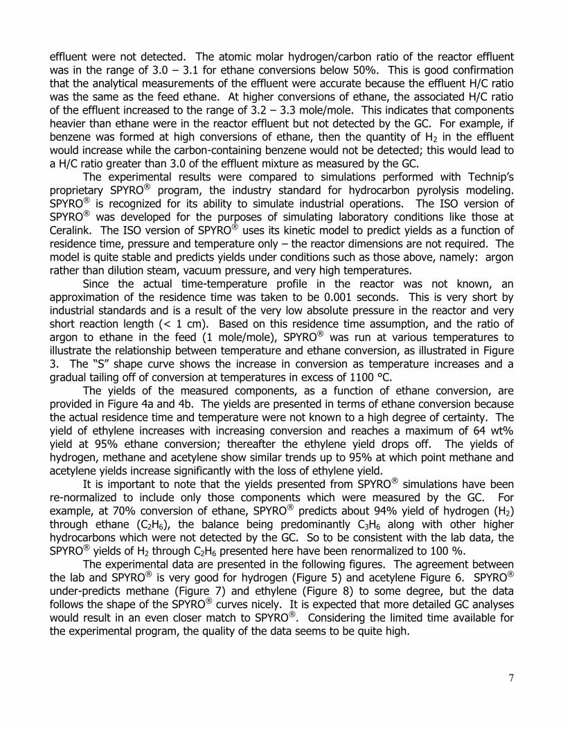
Since the actual time-temperature profile in the reactor was not known, an approximation of the residence time was taken to be 0.001 seconds. This is very short by industrial standards and is a result of the very low absolute pressure in the reactor and very short reaction length (< 1 cm). Based on this residence time assumption, and the ratio of argon to ethane in the feed (1 mole/mole), SPYRO® was run at various temperatures to illustrate the relationship between temperature and ethane conversion, as illustrated in Figure 3. The “S” shape curve shows the increase in conversion as temperature increases and a gradual tailing off of conversion at temperatures in excess of 1100 °C.
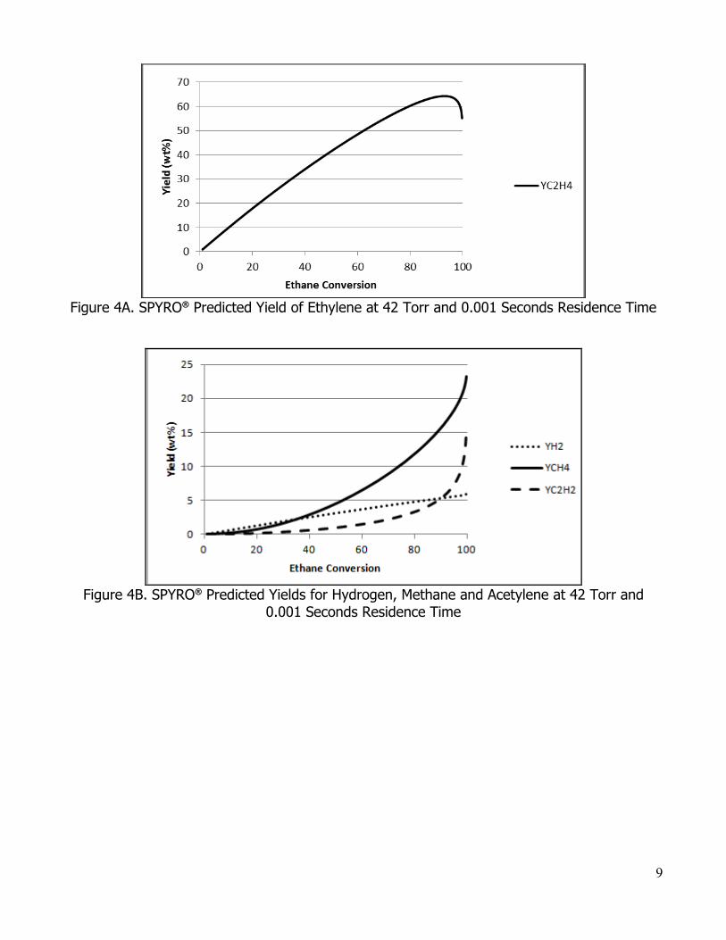
The yields of the measured components, as a function of ethane conversion, are provided in Figure 4a and 4b. The yields are presented in terms of ethane conversion because the actual residence time and temperature were not known to a high degree of certainty. The yield of ethylene increases with increasing conversion and reaches a maximum of 64 wt% yield at 95% ethane conversion; thereafter the ethylene yield drops off. The yields of hydrogen, methane and acetylene show similar trends up to 95% at which point methane and acetylene yields increase significantly with the loss of ethylene yield.
It is important to note that the yields presented from SPYRO® simulations have been re-normalized to include only those components which were measured by the GC. For example, at 70% conversion of ethane, SPYRO® predicts about 94% yield of hydrogen (H2) through ethane (C2H6), the balance being predominantly C3H6 along with other higher hydrocarbons which were not detected by the GC. So to be consistent with the lab data, the SPYRO® yields of H2 through C2H6 presented here have been renormalized to 100 %.
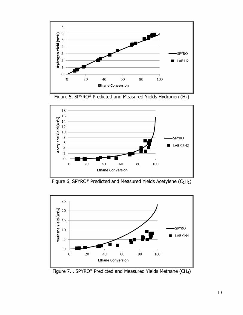
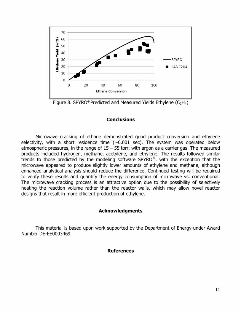
The experimental data are presented in the following figures. The agreement between the lab and SPYRO® is very good for hydrogen (Figure 5) and acetylene Figure 6. SPYRO® under-predicts methane (Figure 7) and ethylene (Figure 8) to some degree, but the data follows the shape of the SPYRO® curves nicely. It is expected that more detailed GC analyses would result in an even closer match to SPYRO®. Considering the limited time available for the experimental program, the quality of the data seems to be quite high.
8
In summary, the experimental program established that microwave energy can be used to supply the endothermic heat required for the pyrolysis of hydrocarbons to olefins. The experimental results were in-line with simulations using the SPYRO® program suggesting that microwaves neither enhance nor inhibit the pyrolysis chemistry. Microwave generation requires electrical input which is inherently less efficient compared to energy generated from combustion of fuel gas as is currently employed in industry. However, conventional heat transfer necessitates many parallel reactor tubes because of limitations on heat flux because of the resistances to heat transfer and the temperature gradient from the hot combustion gas to the cooler process gas. There may be advantages of microwave heat transfer compared to conventional heat transfer which relax current constraints and thereby allow novel reactor designs that result in more efficient production of ethylene. Those design exercises were beyond the scope of this project. In addition to industrial reactor design, it would be very interesting if further experimental work could be performed at elevated pressures and with the use of dilution steam to aid the microwave heat transfer mechanism.
Figure 3. SPYRO® Predicted Ethane Conversion at 42 Torr and 0.001 Seconds Residence Time
9
Figure 4A. SPYRO® Predicted Yield of Ethylene at 42 Torr and 0.001 Seconds Residence Time
Figure 4B. SPYRO® Predicted Yields for Hydrogen, Methane and Acetylene at 42 Torr and 0.001 Seconds Residence Time
10
Figure 5. SPYRO® Predicted and Measured Yields Hydrogen (H2)
Figure 6. SPYRO® Predicted and Measured Yields Acetylene (C2H2)
Figure 7. . SPYRO® Predicted and Measured Yields Methane (CH4)
11
Figure 8. SPYRO® Predicted and Measured Yields Ethylene (C2H4)
Conclusions
Microwave cracking of ethane demonstrated good product conversion and ethylene selectivity, with a short residence time (~0.001 sec). The system was operated below atmospheric pressures, in the range of 15 – 55 torr, with argon as a carrier gas. The measured products included hydrogen, methane, acetylene, and ethylene. The results followed similar trends to those predicted by the modeling software SPYRO®, with the exception that the microwave appeared to produce slightly lower amounts of ethylene and methane, although enhanced analytical analysis should reduce the difference. Continued testing will be required to verify these results and quantify the energy consumption of microwave vs. conventional. The microwave cracking process is an attractive option due to the possibility of selectively heating the reaction volume rather than the reactor walls, which may allow novel reactor designs that result in more efficient production of ethylene.
Acknowledgments
This material is based upon work supported by the Department of Energy under Award Number DE-EE0003469.
References
12
1. Moisan, M., et al., A Waveguide-based launcher to sustain long plasma columns through the propogation of an electromagnetic surface wave. IEEE Transactions on Plasma Science, 1984. PS-12(3): p. 203-214.
2. Walkiewicz, J.W., G. Kazonich, and S.L. McGill, Microwave heating characteristics of selected minerals and compounds. Minerals and Metallurgical Processing, 1988: p. 39-42.