Microwave Theory and TechniquesProf. Girish Kumar
Department of Electrical Engineering Indian Institute of Technology, Bombay
Module - 8Lecture - 40
Microwave Tubes – III: Crossed Field Tubes- Magnetron
Hello, in the last lecture, we discussed reflex klystron, its working, its applications and a
specifications of practically available reflex klystron. After that we started discussion on
travelling wave tubes, then we discussed about slow wave structures, and how and why
we use slow wave structures in travelling wave tubes. And then we started discussion on
helix travelling wave tubes.
(Refer Slide Time: 00:57)
We have discussed the structure of helix travelling wave tubes. Today I will start with
working of helix travelling wave tubes, then I will discuss the cross field microwave
tubes such as magnetron. So, let us begin with working of helix travelling wave tubes.
(Refer Slide Time: 01:18)
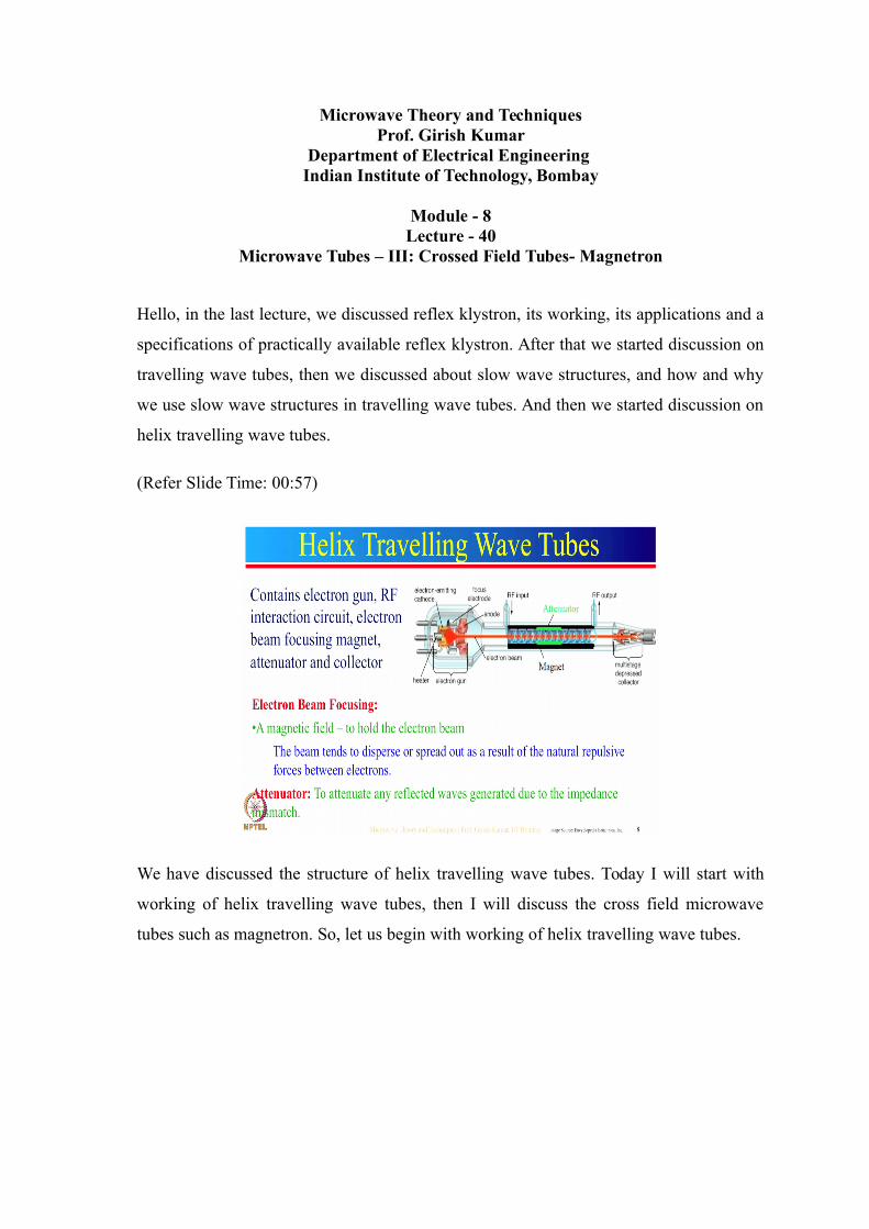
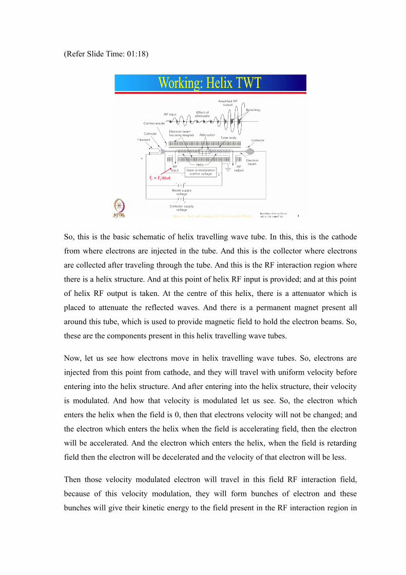
So, this is the basic schematic of helix travelling wave tube. In this, this is the cathode
from where electrons are injected in the tube. And this is the collector where electrons
are collected after traveling through the tube. And this is the RF interaction region where
there is a helix structure. And at this point of helix RF input is provided; and at this point
of helix RF output is taken. At the centre of this helix, there is a attenuator which is
placed to attenuate the reflected waves. And there is a permanent magnet present all
around this tube, which is used to provide magnetic field to hold the electron beams. So,
these are the components present in this helix travelling wave tubes.
Now, let us see how electrons move in helix travelling wave tubes. So, electrons are
injected from this point from cathode, and they will travel with uniform velocity before
entering into the helix structure. And after entering into the helix structure, their velocity
is modulated. And how that velocity is modulated let us see. So, the electron which
enters the helix when the field is 0, then that electrons velocity will not be changed; and
the electron which enters the helix when the field is accelerating field, then the electron
will be accelerated. And the electron which enters the helix, when the field is retarding
field then the electron will be decelerated and the velocity of that electron will be less.
Then those velocity modulated electron will travel in this field RF interaction field,
because of this velocity modulation, they will form bunches of electron and these
bunches will give their kinetic energy to the field present in the RF interaction region in
the next cycle. So, this is how electrons will move in the RF interaction region and
output will be taken from this point. And after giving up their kinetic energy to helix at
this point, they will be collected by the collector.
Now, let us see how bunching takes place, and how and what are the effect of attenuator.
So, initially input RF signal V s equal to V 1 sin omega t is given to this helix. Because
of this initial signal bunching of electrons will take place like this. And these bunches
will give up their kinetic energy to the RF field present there in the next cycle; and
because of that amplification of RF signal will take place. As you can see from these
two, so this is the amplified signal as compared to this one. So, this amplified RF signal
will produce denser bunches of electron, and those denser bunches of electron will
further amplify the RF signal, RF signal is continuously amplified.
And this RF signal is amplified till the attenuator. And at the attenuator the RF signal is
attenuated; and after that the same process of bunching and transfer of kinetic energy
from electron beam to RF signal takes place like this. So, this is how the RF signal in
helical structure is amplified. One more thing during the interaction of electron beam and
the RF signal, we have not talked about the velocities of these two. The velocity of is
made comparable by the helical structure present in the helix travelling wave tube.
As we discussed earlier this helical structure reduces the phase velocity of the
electromagnetic wave. And because of that electron beam and electromagnetic wave get
enough time to interact with each other. The amount by which the velocity of
electromagnetic wave is decreased, that can be decided by the number of turns of the
helix and the diameter of the helix. So, this is all about the working of helix travelling
wave tubes. Now, let us move onto the specifications of practically available helix
travelling wave tubes.
(Refer Slide Time: 06:45)
So, the range of frequencies over which the helix travelling wave tubes can work is from
1 gigahertz to 100 gigahertz; and it can generate output powers up to 10 kilowatt
average. And the gain the helix travelling wave tubes can generate is up to 10 dB and the
efficiency of helix travelling wave tubes is about 20 to 40 percent.
(Refer Slide Time: 07:27)
Now, let us see applications of helix travelling wave tubes. The helix travelling wave
tubes can be used an broad band microwave receivers as a low noise RF amplifiers. And
in wideband communication links and long distance telephony, we need repeaters to
amplify the signals; and in those repeaters these helix travelling wave tubes can be used
as an amplifier to amplify the signals. And the helix travelling wave tubes can be used in
communication satellites also as an power output tube. These helix travelling wave tubes
can also be used for medium power or high power satellite transponder outputs; and
because of their higher powers and large bandwidth, they can also be used in troposcatter
links.
Few more applications of helix travelling wave tubes are such as they can be used an air
borne, ship borne, pulse high power radars. They can also be used in electronic counter
measure system ECM. And they can also be used in phased array radars. So, this is all
about the applications of helix travelling wave tubes.
(Refer Slide Time: 08:50)
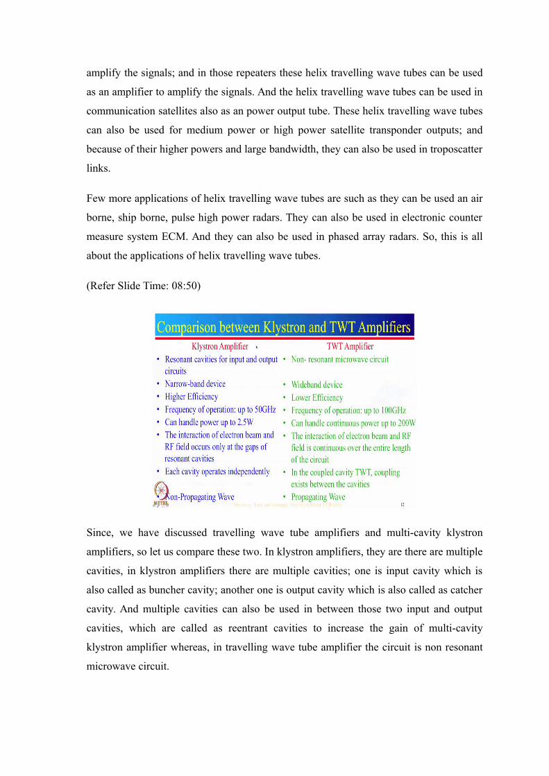
Since, we have discussed travelling wave tube amplifiers and multi-cavity klystron
amplifiers, so let us compare these two. In klystron amplifiers, they are there are multiple
cavities, in klystron amplifiers there are multiple cavities; one is input cavity which is
also called as buncher cavity; another one is output cavity which is also called as catcher
cavity. And multiple cavities can also be used in between those two input and output
cavities, which are called as reentrant cavities to increase the gain of multi-cavity
klystron amplifier whereas, in travelling wave tube amplifier the circuit is non resonant
microwave circuit.
Now, the next difference is the klystron amplifier is a narrow band device whereas;
travelling wave tube amplifier is a wideband device. And the klystron amplifiers have
higher efficiency as compared to the travelling wave tube amplifiers. And as we
discussed earlier the frequency of operation of klystron amplifier is up to 50 gigahertz,
whereas the frequency of operation of a travelling wave tube amplifier is up to 100
gigahertz. And klystron amplifiers are the low power amplifiers. So, they can handle up
to 2.5 watts only; whereas, the travelling wave tube amplifiers are the high power
amplifiers when which can handle up to 200 watts of power.
The one more major difference between klystron amplifier and travelling wave tube
amplifier is that the interaction of electron beam and the RF field occurs only at the
edges of resonant cavities in the klystron amplifier. Whereas, in the travelling wave tube
amplifier, the interaction of electron beam and the RF field is continuous over the entire
length of the circuit or over the entire helical structure; and in klystron amplifiers each
cavity operates independently, whereas in coupled cavity travelling wave tubes coupling
edges between the cavities. And the last difference is the wave in klystron amplifier is
non-propagative; whereas the wave in travelling wave tube is propagative. So, this is all
about the differences between klystron amplifier and travelling wave tube amplifiers. Till
now we have discussed about the linear beam tubes, their different classifications.
(Refer Slide Time: 11:34)
Now, we will discuss M-type tubes. M-type microwave tubes are also called as crossed
field microwave tubes, in which dc electric field is perpendicular to the dc magnetic
field. As the name crossed field itself suggest that the fields are perpendicular to each
other. And these crossed field tubes are of three types; first one is resonant type, second
one is non resonant and the last one is the structures based on maser effect.
Now, what is maser effect? Maser is microwave amplification by stimulated emission of
radiation. And the example of the microwave tubes which work on the principle of maser
effect is gyrotron. So, the gyrotron generates high frequency electromagnetic wave by
stimulated cyclotron resonance of electrons moving through strong magnetic fields. And
these gyrotrons can generate output frequencies up to 500 megahertz. And these gyrotron
can produce output frequencies from 20 gigahertz to about 500 gigahertz. And they can
produce output powers up to 2 megawatts. And the gyrotron microwave tubes are used in
industrial heating applications such as in nuclear fusion, they are used to heat the
plasmas. So, this is all about the gyrotron.
Now, in the resonant structures there are standing waves and multiple reentrant cavities
are used in these type of microwave tubes. The example of resonant microwave tubes is a
magnetron and the non resonant type of structures can be classified as forward wave
structures and backward wave structures. And further can be classified as the structures
which has reentrant cavities and the structures without reentrant cavities. So, this is all
about the classification of crossed field microwave tubes.
(Refer Slide Time: 14:15)
Now, move on to the magnetron oscillators. Generally magnetron oscillators contain
some form of cathode and anode which are operated in dc magnetic field normal to the
dc electric field. And because of this crossed field, the movement of electrons will be in a
curved path. These magnetron oscillators are of three types; first one is split-anode
magnetron, second one is cyclotron frequency magnetron, and the third one is travelling
wave magnetron. The split-anode magnetron use static negative resistance between two
segments of the anode. And because of this the efficiency of these type of oscillators is
low and these are useful below microwave frequency.
And the cyclotron-frequency magnetrons operates under the influence of synchronization
between the electric field and the oscillation of electrons parallel to the electric field. And
these type of magnetrons have low efficiency and they can produce low output powers
only. And in travelling-wave magnetrons, there is a interaction of electrons with
electromagnetic field. As we discussed in the travelling wave linear beam tubes, so
because of travelling wave structures they can produce high output powers and they have
better efficiency as compared to the other two. And there are many types of travelling
wave magnetrons such as cylindrical magnetron, linear magnetron, coaxial magnetron
and voltage-tunable magnetron, inverted coaxial magnetron and frequency-agile
magnetron.
The working of all of these type of magnetrons is somewhat similar. So, we will discuss
only this one cylindrical magnetron. The difference in the cylindrical magnetron and
planar or linear magnetron is of their structure. In cylindrical magnetron the cathode and
the anode are of cylindrical form; whereas, in linear or planar magnetron, the cathode
and anode are of planar form or linear form. And the voltage-tunable magnetrons are the
broadband magnetrons in which frequency changes if we vary the applied voltage
between the anode and the sole. So, this is all about these.
(Refer Slide Time: 17:33)
Now, let us discuss the cylindrical magnetron. The cylindrical magnetron is also called as
multi-cavity magnetron. In this the cathode and the anode are of cylindrical shape. And
the cathode and the filament is placed at the centre of the tube. And these are supported
by the filament leads. The cathode is made up of high emission material, so that it can
emit electrons when it is heated indirectly.
And the space between anode and cathode is called as RF interaction space. And there
are 8 to 20 cylindrical cavities all around the circumference of the cathode. And those
cavities are called as resonant cavities or reentrant cavities. And for each cavity there is a
slot which connects the cavity to the RF interaction space. And each one of these cavities
acts as a parallel resonant circuit as shown by this. So, this is a parallel resonant circuit or
a tank circuit and the resonant frequency of a parallel resonant circuit is given by f r is
equal to 1 upon 2 pi under root 1 by LC.
The slot which connects the cavity with the interaction region acts as a capacitor. And the
cavity walls acts as an inductor. So, the capacitance can be determined by the physical
dimension of this gap, and the inductance can be determined by the physical dimension
of this cavity. So, the resonant frequency of this cavity can be determined by the physical
dimensions of the cavity. Now, one more thing the dc voltage is applied between cathode
and anode; and magnetic field is applied along the axis of the cathode. So, electric field
is radially in this plane, and magnetic field is in this direction.
So, electric and magnetic fields are perpendicular to each other. And by varying the DC
voltage V naught, and the magnetic field the path of electron can be changed. So, by
properly selecting these two parameters - dc voltage and the magnetic field, the electrons
path can be made cycloidal, and that depends on the dc voltage and the magnetic flux.
So, this is all about the structure of a multi-cavity magnetron.
(Refer Slide Time: 20:49)
Now, let us move onto the working of multi-cavity magnetron. So, the working of multi-
cavity magnetron can be divided into four phases. Phase one is generation and
acceleration of electron beam in a dc field. And the second phase is velocity-modulation
of electron beam in an ac field. And the third phase is bunch formation or space-charge
wheel formation; and the last phase is dispensing of energy to the ac field. Now, we will
discuss these phases one by one. Let us discuss the first phase which is generation and
acceleration of electron beam in a dc field.
(Refer Slide Time: 21:33)
So, positive voltage is given to this anode. And this is negative with respect to this anode.
So, the electric field lines will be from positive to negative that is from anode to cathode
radially inward. And the force on the electron will be F is equal to q v. So, the force on
electron will be from cathode to anode radially outward. So, if there is no magnetic field
then there will be only dc electric force from cathode to anode on electrons. So, all the
electrons emitted from this cathode will move radially towards the anode like this blue
line.
Now, if a weak magnetic field is applied, then the resultant force on the electron will be
in this direction. So, electron will move in this path. Now, if we increase the magnetic
field strength, then the path of electron will be bent more. And we further increase the
magnetic field strength, then at one point there will be deflection of the electron from the
anode and that will return to the cathode. And at this point of time, there will be no
current in the tube. So, the strength of magnetic field, after which there is no current in
the microwave tube it is called as cut off magnetic field and that is given by hull cut off
magnetic equation. Similarly, the cut off dc voltage is given by hull cut off voltage
equation. So, this is the effect of different magnetic flux densities on the path of electron
beam.
Now, let us see the effect of ac field on the path of electron beam. So, dc electric field is
present from anode to cathode radially inward. One more thing if one cavity starts
oscillating, then it excites the next cavity with the phase delay of 180 degree. And
because of this there will be ac electric field in the cavity. And the overall electric field in
this structure will be sum of dc electric field and the ac electric field. So, the electrons
will move radially outwards from cathode to anode because of the dc electric field. And
as they enter into the ac electric field their path will be bent. So, the electron which
moves towards the positive portion of the anode or the portion which is more positively
charged those electrons will be accelerated and they will be deflected from this anode.
And the electrons which move towards the less positively charged part of the anode those
electrons will be decelerated and their energy will be transferred to the ac field present
there. So, this is how the electron transfer their energy to the ac field present in the
cavity.
Now, let us move onto the a space charge wheel formation. So, because of velocity
modulation of electron by the fields present here, and the cumulative action of electrons
going from cathode to anode and some electrons returning from anode to cathode. The
combined action of these three result in a structure resembling the moving spokes of a
wheel. Now, let us see how oscillations are sustained in this structure. All the electrons
which are emitted from this cathode get energy from the dc electric field some of those
electron transfer their kinetic energy to the ac field present in the cavities. And those
electron help in sustaining the oscillations as they take energy from the dc fields and give
up their energy to the ac fields. So, this is how the oscillations are sustained in multi-
cavity magnetron.
(Refer Slide Time: 26:37)
Now, let us move onto the specifications of a magnetron. The range of frequencies over
which the magnetron can work is from 500 megahertz to about 12 gigahertz. And the
power output which can be produced by magnetrons is up to about 40 megawatt. And
this can be achieved when we give dc voltage of about 50 kilovolt at about 10 gigahertz.
And the efficiency of these type of magnetrons is fairly good which is from 40 to 70
percent. The example of the magnetron is Thomson TH3074A magnetron in which the
frequency ranges from 8.5 to 9.5 gigahertz. And it can generate power up to 220
kilowatt. So, anode voltage is equal to 21.5 kilovolt. And the anode current is 27.4
ampere.
(Refer Slide Time: 27:46)
Now, let us move onto the applications of magnetron oscillators. So, magnetron
oscillators can be used in radar transmitters. They can also be used in industrial heating.
And there is a very known example of magnetron which is microwave oven. And the
standard power of this microwave oven is about 600 watt and the frequency over which
it work is a about 2.5 gigahertz and it can also work on 915 megahertz. So, this is all
about the applications of the magnetrons.
(Refer Slide Time: 28:23)
Now, let us move onto the comparison of microwave tubes. So, this vertical axis is the
average power that can be provided by the microwave tubes. And this horizontal axis is
the frequencies over which these microwave tubes can work. So, as we discussed helix
travelling wave tubes can work from below microwave frequencies to about hundreds of
gigahertz and this can provide output powers from few kilowatt to few watts. And as the
frequency increases, the power provided by these microwave tubes decreases. And as we
discussed the klystron microwave tubes can work from fraction of gigahertz to about
hundreds of gigahertz. And it can provide high powers of about few megahertz for a very
large range of frequencies up to about 10 gigahertz.
And as frequency increases power, output decreases drastically and at very high
frequency that is at 100 gigahertz, it can provide only tens of watts of power. As I
discussed gyrotron works from 20 gigahertz to about 500 or 600 gigahertz. And they can
provide high powers of about 2 megawatts for a large range of frequencies that is from
20 gigahertz to about 200 gigahertz and after that power output decreases drastically and
at about 500 or 600 gigahertz. It can provide only tens of watt of power. So, depending
upon the power output requirement; and the range of frequencies any particular
microwave tubes can be selected. So, this is all about the microwave tubes.
Just to summarize in microwave tubes we started with a linear beam tubes in which the
working principle is velocity and current modulation. We discussed two cavity klystron,
three cavity klystron, and then we discussed reflex klystron oscillator. And these three
are low power microwave tubes after that we discussed helix travelling wave tubes in
which slow wave structures are used to slow down the electromagnetic waves. After that
we discussed about crossed field microwave tubes, and we discussed little bit about
gyrotrons, and we discussed magnetron in detail.
Thank you.