Microwave Vision: From RF Safety to Medical Imaging Angie Fasoula 1 , Shoaib Anwar 1 , Yann Toutain 1 , Luc Duchesne 1 1 Microwave Vision Group (MVG), Paris, France, [email protected]Abstract—This article gives an overview of the activities of the company Microwave Vision, formerly Satimo, oriented to health-related applications. The existing products in terms of Specific Absorption Rate (SAR) measurement and RF safety are described in detail. The progress of the development of a new imaging modality for breast pathology detection using microwaves is shortly reported. Index Terms—antenna, propagation, measurement, microwave imaging, medical imaging I. INTRODUCTION Nowadays, we experience a fast evolution of the society, based on technological progress and societal trends, that tend to connect people and applications with more and more wireless and telecommunication devices. This is a fundamental evolution that won’t stop in the next years and decades. In order to accompany the installation and the use of a very fast increasing number of radiating devices, regulations have been put in place progressively. Specific devices, also called RF safety devices, aimed at measuring this new electromagnetic environment in which we are living daily, have been developed: systems to measure the Specific Absorption Rate (SAR) of mobile phones in the market, exposimeters that monitor the field levels for workers or in the streets of the towns, etc. The frequency spectrum that is used for the different telecommunication systems is also becoming larger and larger, while the protocols of communication are becoming more and more complex. In the coming years for instance, the 5G protocol will be progressively implemented worldwide with frequencies up to 110 GHz and bandwidths close to 200 MHz that can be aggregated up to 1 GHz. In order to cover this large variety of applications, exposimeters have to become frequency- selective, adaptive, having variable sensitivities, etc. The denser and denser network of radiating devices implies also the use of specific simulation software that can reach the required spatial resolution, which can’t be achieved only by using exposimeters with measurement points at limited number of locations. Electromagnetic waves, beside telecommunications and information transfer, can also be used in medical applications. This is a relatively recent evolution that started in the late 80’s / early 90’s, with the first experiments of hyperthermia, using microwave emission to heat the zone where a tumor was developing. There were several difficulties at that epoch, but since then the technology has evolved significantly in terms of efficacy and precision, thanks, among others, to improved simulation tools. Breast cancer is a main concern nowadays and activities involving non-ionizing microwaves (in contrary to X-rays) for detection of breast pathologies have also emerged since about 10 to 15 years, involving numerous scientific teams around the world. The goal is the detection and localization of tumors inside the breast, using electromagnetic waves and advanced algorithms for image reconstruction. The company Microwave Vision, formerly Satimo, was founded 30 years ago and started its activities in the field of antenna measurement systems. In 2007, the company decided to extend its product portfolio to environmental and RF safety testing, including SAR measurement systems and exposimeters. Some years ago, an R&D action in the medical domain has also been initiated, thus transposing the technology of multi-sensor systems for ultra-fast antenna measurement [1] to microwave medical scanners. In this article, the Microwave Vision activities in the RF safety and in the medical domain are presented in detail. II. SAR MEASUREMENTS Each commercial mobile device should comply with ElectroMagnetic Field (EMF) exposure limits, as specified by the regulatory authorities (SAR values). SAR is defined as the power absorbed by a unit mass of human body, and is measured in Watts/Kg. In 1998, the International Commission on Non-Ionizing Radiation Protection (ICNIRP) issued guidelines to limit electromagnetic field (EMF) exposure [2]. In 2001, the European committee for electrotechnical standardization (CENELEC) published protocols for SAR measurements between 300 MHz and 3 GHz for handheld devices (EN 50360 and EN 50361). In addition, today there are two major standards for SAR measurements: The International Electrotechnical Commission (IEC) 62232, and the IEEE 1528 standards [3]- [4]. A. SAR measurement solution at MVG Microwave Vision Group (MVG) started working on SAR measurement equipment in the early 2000s. A complete measurement system was then developed [5] fully compliant with the actual standards. The system has been updated ever since, following the standards evolution, such that a reliable
Transcript
Microwave Vision: From RF Safety to Medical
Imaging
Angie Fasoula1, Shoaib Anwar1, Yann Toutain1, Luc Duchesne1 1 Microwave Vision Group (MVG), Paris, France, [email protected]
Abstract—This article gives an overview of the activities of
the company Microwave Vision, formerly Satimo, oriented to health-related applications. The existing products in terms of
Specific Absorption Rate (SAR) measurement and RF safety are described in detail. The progress of the development of a new imaging modality for breast pathology detection using
microwaves is shortly reported.
Index Terms—antenna, propagation, measurement,
microwave imaging, medical imaging
I. INTRODUCTION
Nowadays, we experience a fast evolution of the society,
based on technological progress and societal trends, that tend
to connect people and applications with more and more
wireless and telecommunication devices. This is a
fundamental evolution that won’t stop in the next years and
decades. In order to accompany the installation and the use
of a very fast increasing number of radiating devices,
regulations have been put in place progressively. Specific
devices, also called RF safety devices, aimed at measuring
this new electromagnetic environment in which we are living
daily, have been developed: systems to measure the Specific
Absorption Rate (SAR) of mobile phones in the market,
exposimeters that monitor the field levels for workers or in
the streets of the towns, etc. The frequency spectrum that is
used for the different telecommunication systems is also
becoming larger and larger, while the protocols of
communication are becoming more and more complex. In
the coming years for instance, the 5G protocol will be
progressively implemented worldwide with frequencies up to
110 GHz and bandwidths close to 200 MHz that can be
aggregated up to 1 GHz. In order to cover this large variety
of applications, exposimeters have to become frequency-
selective, adaptive, having variable sensitivities, etc. The
denser and denser network of radiating devices implies also
the use of specific simulation software that can reach the
required spatial resolution, which can’t be achieved only by
using exposimeters with measurement points at limited
number of locations.
Electromagnetic waves, beside telecommunications and
information transfer, can also be used in medical
applications. This is a relatively recent evolution that started
in the late 80’s / early 90’s, with the first experiments of
hyperthermia, using microwave emission to heat the zone
where a tumor was developing. There were several
difficulties at that epoch, but since then the technology has
evolved significantly in terms of efficacy and precision,
thanks, among others, to improved simulation tools. Breast
cancer is a main concern nowadays and activities involving
non-ionizing microwaves (in contrary to X-rays) for
detection of breast pathologies have also emerged since
about 10 to 15 years, involving numerous scientific teams
around the world. The goal is the detection and localization
of tumors inside the breast, using electromagnetic waves and
advanced algorithms for image reconstruction.
The company Microwave Vision, formerly Satimo, was
founded 30 years ago and started its activities in the field of
antenna measurement systems. In 2007, the company
decided to extend its product portfolio to environmental and
RF safety testing, including SAR measurement systems and
exposimeters. Some years ago, an R&D action in the medical
domain has also been initiated, thus transposing the
technology of multi-sensor systems for ultra-fast antenna
measurement [1] to microwave medical scanners. In this
article, the Microwave Vision activities in the RF safety and
in the medical domain are presented in detail.
II. SAR MEASUREMENTS
Each commercial mobile device should comply with
ElectroMagnetic Field (EMF) exposure limits, as specified
by the regulatory authorities (SAR values). SAR is defined
as the power absorbed by a unit mass of human body, and is
measured in Watts/Kg. In 1998, the International
Commission on Non-Ionizing Radiation Protection
(ICNIRP) issued guidelines to limit electromagnetic field
(EMF) exposure [2]. In 2001, the European committee for
electrotechnical standardization (CENELEC) published
protocols for SAR measurements between 300 MHz and 3
GHz for handheld devices (EN 50360 and EN 50361). In
addition, today there are two major standards for SAR
measurements: The International Electrotechnical
Commission (IEC) 62232, and the IEEE 1528 standards [3]-
[4].
A. SAR measurement solution at MVG
Microwave Vision Group (MVG) started working on
SAR measurement equipment in the early 2000s. A complete
measurement system was then developed [5] fully compliant
with the actual standards. The system has been updated ever
since, following the standards evolution, such that a reliable
and up-to-date system for certification and R&D purposes all
over the world is assured.
SAR measurements are quite complex and time-
consuming. MVG has put a lot of effort on reducing this
time, as it can be a critical parameter in the development
process of new mobile devices. The so far developed
techniques employ, either different algorithms to reduce the
2D and 3D scanning time while maintaining the uncertainty
levels within the standard limits [6], or an innovative very
fast multi-probe method for SAR estimation [7].
A typical MVG SAR bench is shown in Fig. 1. It consists
of a 6-axes robotic arm which controls the probe movement
inside the SAR phantoms and assures precise E-field
measurement. The mobile phone device is placed below the
SAR liquid containers, using precise positioning systems.
The mobile device is controlled by an RF signal emulator
which forces the mobile device to emit at maximum power at
the desired frequency and technology (2G, 3G, LTE, etc.).
The SAR liquids used in the phantoms have selected
properties, such that the human body tissue is realistically
simulated at the specific frequency band of interest. The
measurement setup is fully automated and remotely
controlled using the OPENSAR software. The measurement
equipment can provide certified measurements from 30 MHz
up to 6 GHz.
Fig. 1. MVG’s SAR measurement system
III. RF SAFETY EQUIPMENT
While SAR measurements provide certified and precise
evaluation of a mobile telecommunication device in terms of
EMF exposure, public concern according to several EU
studies is more focused on the effects of exposure due to
base station antennas (BTS) [8]. In order to propose a
simpler procedure to evaluate the EMF exposure, ICNIRP
and the World Health Organization (WHO) have defined
reference levels for human exposure in Volts/meter deduced
from basic restriction levels of SAR values [2],[9].
MVG has been involved in several research projects
since 2003 regarding the EMF exposure along with the major
stakeholders in this domain (mobile phone manufacturers,
service providers, public regulatory bodies, research
organizations, and the academia) [10]. From this rich
collaborative research experience, MVG has developed over
the years, several state-of-the-art EMF exposure
measurement equipment [11].
A. MVG exposimeters
Exposimeters (or dosimeters) are portable devices,
capable to carry out precise isotropic E-field measurements.
There are two types of exposimeters.
The EME Guard family is destined for professionals
working in close proximity of radiating elements (base
stations, broadcast centers, radars, etc.). It provides precise
broadband (from 27 MHz up to 40 GHz) E-field exposure
levels and alerts the user if the exposure exceeds the
thresholds defined by the standardized limits [2], [9].
The EME Spy family is designed to provide frequency-
selective E-field measurements with excellent isotropy,
according to the IEC protocols and ICNIRP guidelines.
These devices are used by local authorities, service
providers, research organizations, and regulatory bodies.
These exposimeters cover the widely deployed wireless
communications bands over the 80MHz – 6 GHz range
(from FM, TV broadcast bands to 2G, 3G, LTE, Wi-Fi
frequency bands). An android app is designed especially for
the purpose of real-time frequency-selective exposure
measurements with GPS localization [11].
The EME Spy exposimeters are based on a fixed filter
RF chain architecture, with RF switches which choose a
given frequency band to measure. If the frequency band
changes from one country to another, the hardware has to be
modified in order to measure the correct band. A short-term
solution to this problem is to design specific exposimeter
devices intended for use in target areas where the frequency
spectrum usage is known. Hence, MVG has developed two
versions of exposimeters intended for the European and
North American market.
For a long term solution for global coverage, a proof of
concept solution has been developed under the collaborative
research project Lexnet [12]. The idea is to use a wideband
homodyne receiver with programmable local oscillator and
baseband filters, in order to adapt to any frequency and
bandwidth in the band [80 MHz-6 GHz].
B. EMF monitoring stations
MVG has developed two types of fixed EMF exposure
monitoring stations.
The FlashRad EMF monitoring solution is based on
broadband EMF measurements from 700 MHz up to 11
GHz. It can monitor dense EMF environments (military
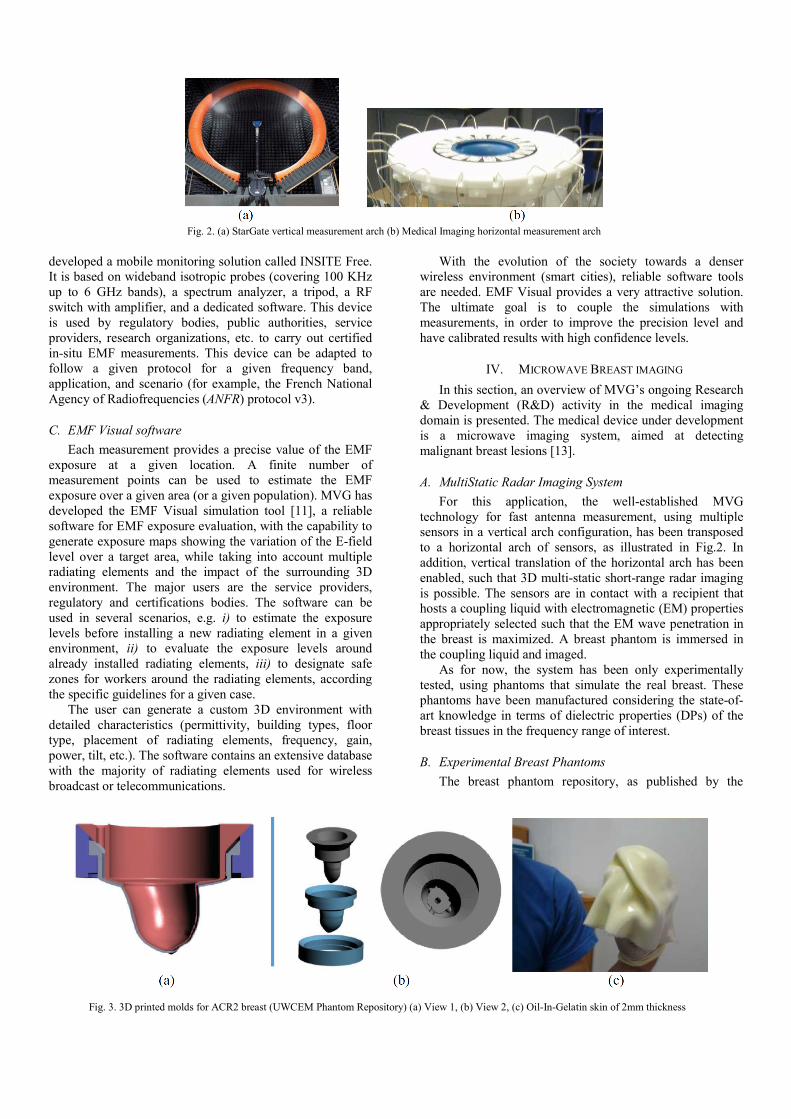
University of Wisconsin [14] has been used to define MRI-
based realistic breast geometries. Using this input, three
molds and an upper supporting ring have been 3D printed for
each breast phantom, as illustrated in Figs.3(a) and (b). From
the inside outwards:
• a mold with contour resulting from the segmentation
of the fibroglandular tissue on the input MRI image,
after the minimal required simplification such that a
single printable mold is defined
• a mold having the shape of the external breast contour
• a second mold with the same shape (i.e. external
breast contour) but slightly dilated, such that a 2mm
radial distance exists between corresponding points
on the external surface of the two molds.
The purpose of the third mold is to use it only for
molding a breast skin layer of 2mm. The Oil-In-Gelatin
(OiG) recipe for breast skin [15] has been applied and an
example of the resulting skin phantom after unmolding is
given in Fig.3(c). The OiG skin is further fit to the external
surface of the breast contour mold and used for the imaging
tests.
Both the fibroglandular tissue and external breast contour
mold are filled with liquids having DPs similar to the ones of
the fibroglandular and fatty tissue correspondingly, as
specified in [16],[17]. We have been inspired by the liquid
recipes published in [18], with slight adjustments in order to
avoid gelification for given Triton-X/Water proportions of
interest.
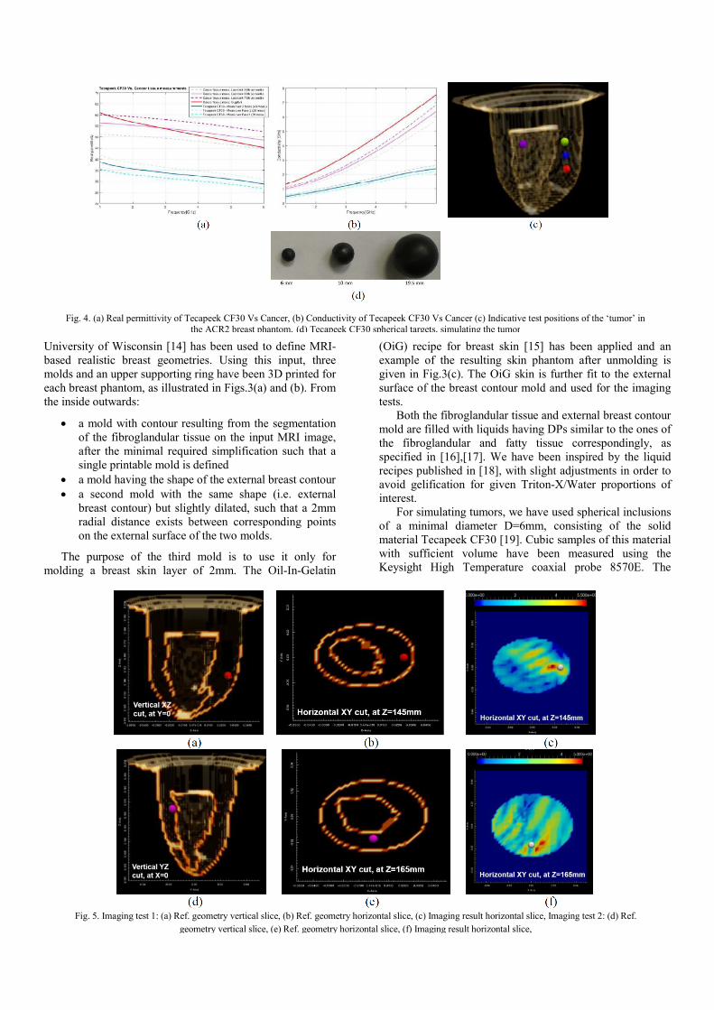
For simulating tumors, we have used spherical inclusions
of a minimal diameter D=6mm, consisting of the solid
material Tecapeek CF30 [19]. Cubic samples of this material
with sufficient volume have been measured using the
Keysight High Temperature coaxial probe 8570E. The
measured real permittivity and conductivity of Tecapeek
CF30 are shown in Fig.4(a) and (b), in comparison with the
cancerous tissue DPs, as specified by Lazebnik et al.[16] and
Sugitani et al. [17]. The DPs of Tecapeek CF30
underestimate the cancerous tissue DPs. Several indicative
test positions of such a ‘tumor’ inclusion of D=6mm placed
in the fatty tissue, but at close proximity to a voluminous
fibro gland, are illustrated in Fig. 4(c) using multi-color
spheres.
C. Imaging Results
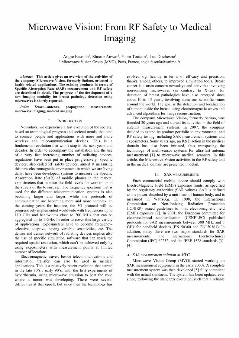
Achieved imaging results for the experimental
configuration of Fig.4(c) are shown in Fig.5 for two target
test positions. The images have been formed using multi-
static radar processing algorithms [20],[21],[22], after
appropriate calibration of the mutual coupling and strong
clutter mitigation.
The imaging results shown in Figs.5(c) and (f) are 2D
slices of the full 3D breast volume, taken at the a priori
known vertical target position. The color scale indicates the
confidence level for anomaly (i.e. tumor) detection at the
given location, with a maximum level of 6 for the specific
algorithm parameterization. These are just preliminary
results illustrating the potential of our imaging system for
detection of small inclusions with limited dielectric contrast
against clutter.
We are progressively increasing the complexity of our
experimental test scenarios, in order to render them more
realistic and better guide the continuing development of our
system (hardware and software). We are ultimately aiming
at working with real breast data.
ACKNOWLEDGMENT
We thank the COST Action TD1301, MiMed for having
invited us to present our work.
REFERENCES
[1] P.O. Iversen, P. Garreau, K. Englund, E. Pasalic, O. Edvardsson, G. Engblom, “Real Time Spherical Near Field Antenna Test Range for Wireless Applications”, Proceedings of AMTA 1999 – Antenna Measurement Techniques Association, pp. 363 – 368, October 4-8 1999, Monterey Bay, California
[2] ICNIRP EMF-Guidelines: “Guidelines for Limiting Exposure to Time-Varying Electric, Magnetic, and Electromagnetic Fields (up to 300 GHz)”, Health Physics Vol. 74, No 4, pp 494-522, 1998.
[3] International Standard, “Determination of RF field strength and SAR in the vicinity of radiocommunication base stations for the purpose of evaluating human exposure”, IEC 62232.
[4] International standard,“IEEE Recommended Practice for Determining the Peak Spatial-Average Specific Absorption Rate (SAR) in the Human Head from Wireless Communications Devices: Measurement Techniques”, IEEE 1528.
[5] SAR measurement equipment developped by MicrowaveVision Group MVG, more information available online at: http://www.mvg-world.com/en/products/field_product_family/sar-38.
[6] J. Luc, R. Butet, Y. Toutain and F. Gallee, "SAR measurement time reducing via optimization algorithms and interpolation scheme poster
and publication", 28th Annual Meeting of the Bioelectromagnetic Society (BEMS), 2006.
[7] R. Butet, Y. Toutain, S. Le Dall, J. Luc, L. J. Foged and J. Estrada, "A fast SAR measurements system for production testing of personal wireless devices," 2013 IEEE Antennas and Propagation Society International Symposium (APSURSI), Orlando, FL, 2013, pp. 2026-2027.
[9] The EMF Project, World Health Organization WHO. [Online]: http://www.who.int/peh-emf/en/.
[10] LEXNET: FP7 EU project, & MVG’s contribution to research projects [Online]:http://www.lexnet.fr/consortium/satimo.html.
[11] RF saftey products developpped by MVG, [Online]: http://www.mvg-world.com/en/products/field_product_family/rf-safety-3.
[12] M. S. Anwar, Y. Toutain, A. Sanchez, D. Dassonville, Y. Fernandez and S. Bories, "Wearable wideband exposimeter design for electromagnetic field exposure measurements," Microwave Conference (EuMC), 2014 44th European, Rome, 2014, pp. 703-706.
[13] R.C.Conceiçao, J.J.Mohr, M.O’Halloran, An Introduction to Microwave Imaging for Breast Cancer Detection, Springer Biological and Medical Physics, Biomedical Engineering, 2016.
[14] E.Zastrow, S.K.Davis, M.Lazebnik., F.Kelcz, B.D. Van Veen and S.C.Hagness, “Database of 3D grid-based numerical breast phantoms for use in computational electromagnetics simulations”, https://uwcem.ece.wisc.edu/phantomRepository.html, 2008.
[15] M.Lazebnik, E.L.Madsen, G.R.Frank and S.C.Hagness, “Tissue-mimicking phantom materials for narrowband and ultrawideband microwave applications”, Physics in Medicine and Biology, Vol. 50, pp.4245-4258, 2005.
[16] M.Lazebnik et al., “A large-scale study of the ultrawideband microwave dielectric properties of normal, benign and malignant breast tissues obtained from cancer surgeries”, Physics in Medicine and Biology, Vol.52, pp. 6093-6115, 2007.
[17] T.Sugitani et al., “Complex permittivities of breast tumor tissues obtained from cancer surgeries”, Applied Physics Letters, Vol. 104, 253702, 2014.
[18] N.Joachimowicz, C.Conessa, T.Henriksson and B.Duchêne., “Breast phantoms for microve imaging”, IEEE Antennas and Wireless Propagation Letters, Vol.13, 2014.
[19] Tecapeek CF30 datasheet, Ensinger Inc. Washington PA, http://www.ensinger-inc.com/products.cfm?page=product&product=tecapeek+cf30+carbon+filled+peek
[20] E.C.Fear, X.Li, S.C.Hagness, and M.A.Stuchly “Confocal Microwave Imaging for breast cancer detection: localization of tumors in three dimensions”, IEEE Transactions on Biomedical Engineering, Vol.49 No.8, 2002.
[21] R. Nilavalan, A. Gbedemah, I. J. Craddock, X. Li, and S. C. Hagness, “Numerical investigation of breast tumour detection using multi-static radar,” Institution of Engineering and Technology. Electroncs Letters. Vol. 39, 2003.
[22] Y.Xie, B.Guo, L.Xu, J.Li, and P.Stoica, “Multistatic adaptive microwave imaging”, IEEE Transactions on Biomedical Engineering, Vol.53, No.8, 2006.


![Vision 3 [Kompatibilit si m d]) - phys.szote.u-szeged.hu · Physiology of vision ... binocular neurons with RF on the horopter ... (Microsoft PowerPoint - Vision_3 [Kompatibilit si](https://static.documents.pub/doc/80x56/5b384e6c7f8b9a5a518d412b/vision-3-kompatibilit-si-m-d-physszoteu-physiology-of-vision-binocular.jpg)


