Page 1
Mid-March 2019, Volume 21, No. 6
Customer Care and Aftersales
New Chevrolet Silverado 4500HD, 5500HD, 6500HD Take on Medium-Duty Market . . .2
Engine Tick or Squeak Noise . . . . .8
Engine Performance and Fuel Range Conditions . . . . . . . . . .9
Frequent Navigation Service Has Expired Message . . . . . . . . . .10
Wheelhouse Liner Interference . .11
Requesting GM Upfitter Technical Assistance . . . . . . . . . . .12
Silverado 4500HD, 5500HD, 6500HD Powertrain Operation
Shipping Hazardous Materials to the Warranty Parts Center
see page 6 see page 5
Take on Medium-Duty Market
4500HD, 5500HD, 6500HDNew Chevrolet Silverado
Page 2
Mid-March 2019– Page 2
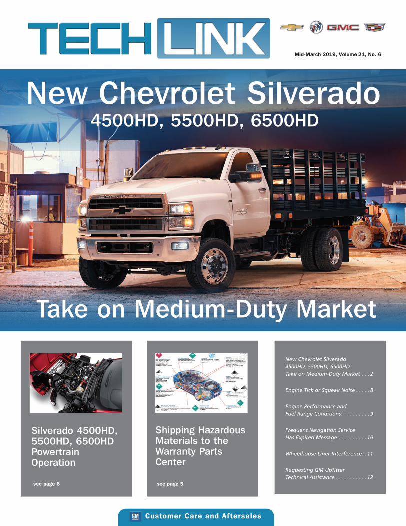
The new 2019 Chevrolet Silverado 4500HD, 5500HD, 6500HD
chassis cab models are the newest entries in the medium-duty
truck market. The trucks are available as regular and crew cab
models in Work Truck (WT) and LT trim levels, both in 2WD
and 4WD configurations. There are a range of wheelbases and
GVWRs.
The Silverado chassis cab features a clean top-of-rail design with
no protruding welds or brackets for smooth, integrated upfits.
Plus, the single-piece frame rails and painted chassis provide
enhanced durability.
DURAMAX DIESELThe standard 6.6L Duramax diesel V8 engine (RPO L5D), paired
with an Allison 6-speed automatic transmission, generates 350
horsepower and 700 lb.-ft. of torque. The engine uses Ultra-Low
Sulfur Highway Diesel Fuel and/or B20 biodiesel with a biodiesel
content up to 20% by volume.
The truck features a tilt-hood opening design for easy access to
the engine. Undo the two hood latches on each side of the hood
and pull at the front of the hood (above the grille) to tilt the
hood and fenders forward. The hood actuator strut lock, located
near the bumper on the passenger’s side, will lock to secure the
hood. Pull up on the hood actuator strut lock to unlock the strut
to allow the hood to close.
BRAKES The Bosch TCS8TA brake system uses a Hydro-Max hydrau-
lic brake booster and master cylinder. The system uses DOT 3
CONTINUED ON PAGE 3
New Chevrolet Silverado 4500HD, 5500HD, 6500HD Take on Medium-Duty Market
Hood actuator strut lock
Clean top-of-rail design
The 6.6L Duramax diesel V8 engine is standard.
Page 3
Mid-March 2019– Page 3
CONTINUED ON PAGE 4
Hydraulic Brake Fluid. The system features antilock braking,
electronic brake force distribution, drag torque control, and trac-
tion control.
The Body Control Module (BCM) monitors the brake pedal posi-
tion sensor signal to determine the brake pedal position. The
brake pressure sensor is used to sense the action of the driver’s
application of the brake pedal. The sensor provides an analog
voltage signal that will increase as the brake pedal is applied. The
Electronic Brake Control Module (EBCM) monitors the brake pres-
sure sensor, which is integral to the brake pressure modulator.
EXHAUST BRAKEThe exhaust brake can be used to enhance the vehicle brake
system and reduce brake lining wear by downshifting to increase
engine speed. The number of downshifts selected is determined
by the length of time the brakes are applied and the rate the
vehicle is slowing. Automatic downshifts will not occur if the
vehicle is in Range Selection Mode.
The exhaust brake only activates when the transmission torque
converter is locked, which varies based on vehicle speed, gear,
and load. To activate the system, press the exhaust brake switch
in the center stack of the instrument panel. The switch indicator
will turn on. Press the switch again to turn off the system. The
switch must be pressed at each vehicle start for the system to be
active.
FOUR-WHEEL DRIVEFour-wheel drive models have manual locking hubs on the front
axle. The locking hubs must be manually turned to Lock before
shifting the transfer case. The hubs may remain in the Lock posi-
tion when road surface traction conditions vary. When four-wheel
drive is not needed, turn the hubs to the Free position. If the
hubs are locked when in two-wheel drive, driveline vibration may
occur.
Use the electronic transfer case knob on the instrument panel to
shift into and out of four-wheel drive. The indicator light on the
knob flashes while the transfer case shifts and remains on when
the shift is complete. If the shift cannot be completed, the trans-
fer case goes back to the last setting. Do not shift the transmis-
sion into gear before the indicator light has stopped flashing to
prevent possible damage to the transfer case.
All of the lights on the transfer case knob will flash on momen-
tarily when the ignition is turned On. The light that remains on
indicates the current state of the transfer case.
AIR RIDE SUSPENSIONThe available rear air suspension provides a smooth ride with
a preset, constant frame height. The air springs on the air ride
suspension take the place of steel springs and adjust to load
changes automatically.
The system can temporarily lower the rear suspension by approxi-
mately six inches using the Air Suspension Dump (ASD) switch
in the center stack of the instrument panel. Pressing the ASD
switch when the vehicle is in Park and the ignition is in the On/
Run position releases air supplied to the rear suspension, lower-
ing (dumping) the rear air suspension for loading. The indicator
on the ASD switch illuminates. When the vehicle is shifted out of
Park, air is filled into the rear air suspension for the proper ride
height and the indicator on the switch will turn off. Vehicles with
the air suspension have an AUX warning lamp immediately to
the left of the ASD switch. The suspension may refill slowly if this
lamp is on.
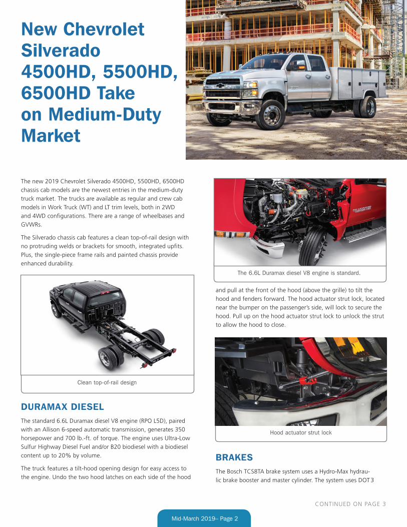
BATTERY BOX
The easy-to-reach battery box (shown with cover removed) is
located under the cab on the driver’s side of the vehicle. An
auxiliary jump-start 12V positive stud with a protective cover is
located beneath the driver’s door and to the left of the batteries.
IN-VEHICLE TECHNOLOGYThe available Commercial Link system enables fleet account own-
ers to manage their vehicles and improve overall fleet efficiency.
Subscribers to the service can use the built-in OnStar connectivity
Manual locking hubs
Dual battery box with cover removed.
Page 4
Mid-March 2019– Page 4
(must be active) to receive useful vehicle data, such as main-
tenance notifications and vehicle location, in order to manage
mileage and expenses more effectively.
In addition, Silverado chassis cab models offer an OnStar 4G LTE
Wi-Fi Hotspot (requires a paid data plan), wireless smartphone
charging and Apple CarPlay and Android Auto support.
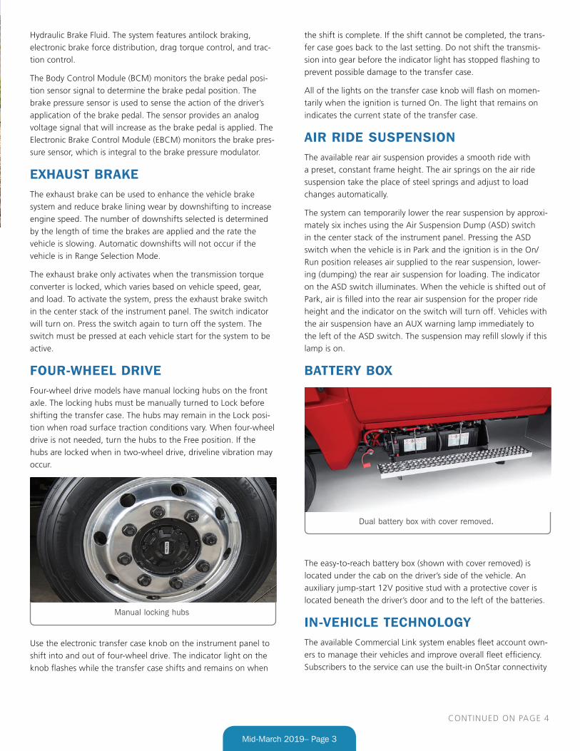
For additional aftermarket electrical accessories, there are up to
four available upfitter switches located on the center stack of the
instrument panel that provide 30 amp circuits.
Some vehicles also may be equipped with a 110/120-Volt AC
power outlet. It can be used to power electrical equipment that
use a maximum of 150 watts. If equipped with a center console,
the power outlet is in front of the cupholders. If equipped with
bench seats, the power outlet is on the center stack.
Available auxiliary switches
Thanks to Bob Briedis and Sherman Dixon
New Chevrolet Silverado 4500HD, 5500HD, 6500HD Take on Medium-Duty Market
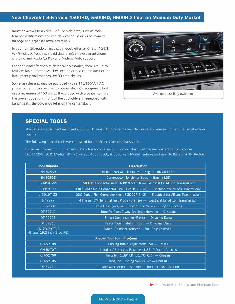
Tool Number Description
EN-52539 Holder, Fan Clutch Pulley — Engine L5D and L5P
EN-52538 Compressor, Tensioner Strut — Engine L5D
J-39197-21 T&B Flex Connector (incl. J-39197-1 x3) — Electrical for Allison Transmission
J-39197-22 0.062 AMP Male Connector (incl. J-39197-2 x3) — Electrical for Allison Transmission
J-39197-23 280 Series Flex Connector (incl. J-39197-3 x3) — Electrical for Allison Transmission
J-47277 4th Gen TCM Terminal Test Probe (Orange) — Electrical for Allison Transmission
GE-52582 Drain Hose (w/ Quick Connect and Valve) — Engine Cooling
DT-52713 Transfer Case 7-way Breakout Harness — Driveline
DT-52709 Pinion Seal Installer (Front) — Driveline Dana
DT-52710 Pinion Seal Installer (Rear) — Driveline Dana
PN 20-2977-2 (8-Lug, 19.5 inch Stud Kit)
Wheel Balancer Adapter — Will Ship Essential
Special Tool Loan Program
CH-52708 Parking Brake Adjustment Tool — Brakes
CH-52707 Installer / Remover, Bushing (1.35" O.D.) — Chassis
CH-52706 Installer, 1.39" I.D. x 1.76" O.D. — Chassis
CH-52705 King Pin Bushing Service Kit — Chassis
DT-52739 Transfer Case Support Adapter — Transfer Case (Meritor)
SPECIAL TOOLSThe Service Department will need a 25,000 lb. hoist/lift to raise the vehicle. For safety reasons, do not use jackstands or
floor jacks.
The following special tools were released for the 2019 Silverado chassis cab.
For more information on the new 2019 Silverado chassis cab models, check out the web-based training course
90319.50W: 2019 Medium-Duty Silverado 4500, 5500, & 6500 New Model Features and refer to Bulletin #18-NA-366.
Page 5
Mid-March 2019– Page 5
For example, if a fuel line received from the parts warehouse is
new and unused, it is not considered a hazmat material. However,
if the same part has been installed in a vehicle and has been in
contact with fuel, it is now considered a hazardous material and
should be shipped following hazmat regulations.
TIP: Hazardous materials should only be shipped to the WPC
using Central Transport. Hazardous materials should never be sent
by air transportation.
RETURNING PARTSIn the interest of safety and complying with requirements, GM
does not accept returns of hazardous material other than core,
warranty returns, and batteries through the Material Return
Program. Hazardous material products not accepted should be
designated as “field scrap” and disposed of by the dealership in
accordance with federal and local regulations.
Thanks to Ed Laskowski
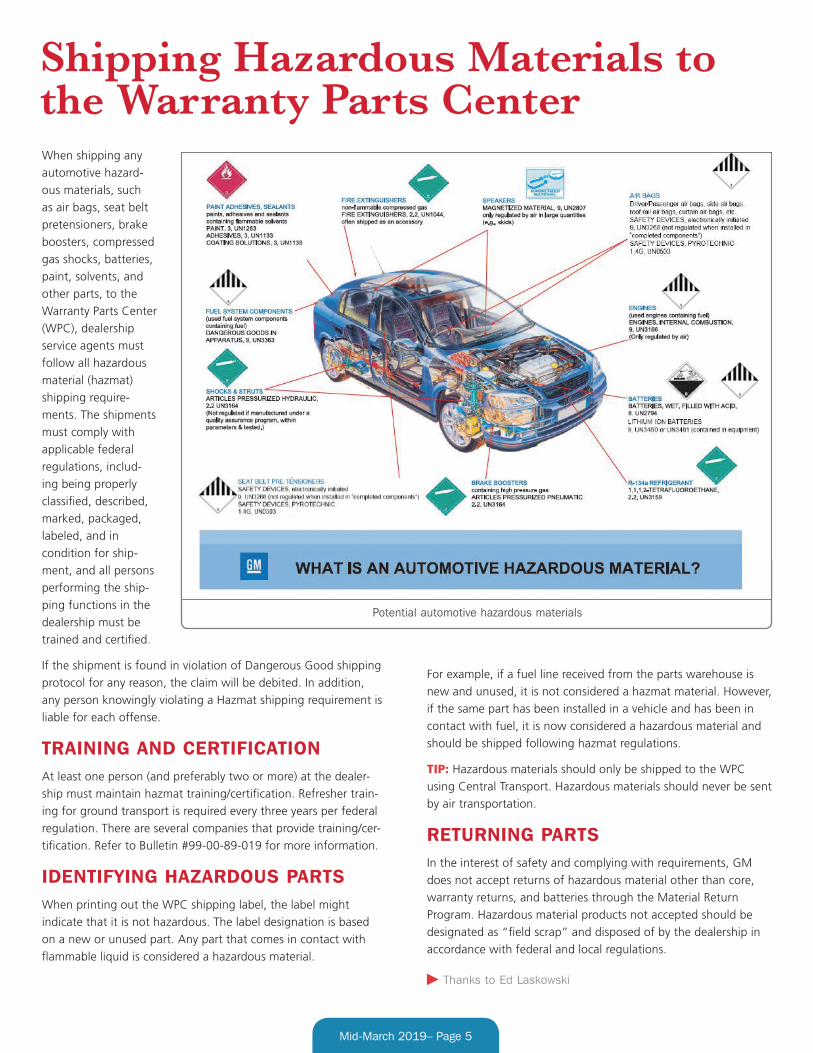
When shipping any
automotive hazard-
ous materials, such
as air bags, seat belt
pretensioners, brake
boosters, compressed
gas shocks, batteries,
paint, solvents, and
other parts, to the
Warranty Parts Center
(WPC), dealership
service agents must
follow all hazardous
material (hazmat)
shipping require-
ments. The shipments
must comply with
applicable federal
regulations, includ-
ing being properly
classified, described,
marked, packaged,
labeled, and in
condition for ship-
ment, and all persons
performing the ship-
ping functions in the
dealership must be
trained and certified.
If the shipment is found in violation of Dangerous Good shipping
protocol for any reason, the claim will be debited. In addition,
any person knowingly violating a Hazmat shipping requirement is
liable for each offense.
TRAINING AND CERTIFICATIONAt least one person (and preferably two or more) at the dealer-
ship must maintain hazmat training/certification. Refresher train-
ing for ground transport is required every three years per federal
regulation. There are several companies that provide training/cer-
tification. Refer to Bulletin #99-00-89-019 for more information.
IDENTIFYING HAZARDOUS PARTSWhen printing out the WPC shipping label, the label might
indicate that it is not hazardous. The label designation is based
on a new or unused part. Any part that comes in contact with
flammable liquid is considered a hazardous material.
Shipping Hazardous Materials to the Warranty Parts Center
Potential automotive hazardous materials
Page 6
Mid-March 2019– Page 6
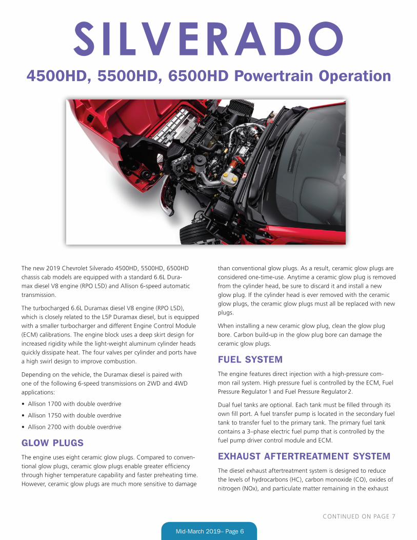
The new 2019 Chevrolet Silverado 4500HD, 5500HD, 6500HD
chassis cab models are equipped with a standard 6.6L Dura-
max diesel V8 engine (RPO L5D) and Allison 6-speed automatic
transmission.
The turbocharged 6.6L Duramax diesel V8 engine (RPO L5D),
which is closely related to the L5P Duramax diesel, but is equipped
with a smaller turbocharger and different Engine Control Module
(ECM) calibrations. The engine block uses a deep skirt design for
increased rigidity while the light-weight aluminum cylinder heads
quickly dissipate heat. The four valves per cylinder and ports have
a high swirl design to improve combustion.
Depending on the vehicle, the Duramax diesel is paired with
one of the following 6-speed transmissions on 2WD and 4WD
applications:
• Allison 1700 with double overdrive
• Allison 1750 with double overdrive
• Allison 2700 with double overdrive
GLOW PLUGSThe engine uses eight ceramic glow plugs. Compared to conven-
tional glow plugs, ceramic glow plugs enable greater efficiency
through higher temperature capability and faster preheating time.
However, ceramic glow plugs are much more sensitive to damage
than conventional glow plugs. As a result, ceramic glow plugs are
considered one-time-use. Anytime a ceramic glow plug is removed
from the cylinder head, be sure to discard it and install a new
glow plug. If the cylinder head is ever removed with the ceramic
glow plugs, the ceramic glow plugs must all be replaced with new
plugs.
When installing a new ceramic glow plug, clean the glow plug
bore. Carbon build-up in the glow plug bore can damage the
ceramic glow plugs.
FUEL SYSTEMThe engine features direct injection with a high-pressure com-
mon rail system. High pressure fuel is controlled by the ECM, Fuel
Pressure Regulator 1 and Fuel Pressure Regulator 2.
Dual fuel tanks are optional. Each tank must be filled through its
own fill port. A fuel transfer pump is located in the secondary fuel
tank to transfer fuel to the primary tank. The primary fuel tank
contains a 3–phase electric fuel pump that is controlled by the
fuel pump driver control module and ECM.
EXHAUST AFTERTREATMENT SYSTEMThe diesel exhaust aftertreatment system is designed to reduce
the levels of hydrocarbons (HC), carbon monoxide (CO), oxides of
nitrogen (NOx), and particulate matter remaining in the exhaust
SILVERADO4500HD, 5500HD, 6500HD Powertrain Operation
CONTINUED ON PAGE 7
Page 7
Mid-March 2019– Page 7
gases. The Diesel Oxidation Catalyst (DOC) removes exhaust HC
and CO through an oxidation process. Particulate Matter (PM),
consisting of extremely small particles of carbon remaining after
combustion, are removed from the exhaust gas by the porous
barrier in the Diesel Particulate Filter (DPF), which lets the gases
pass through and retains the particulates. Diesel Exhaust Fluid
(DEF) is injected into the exhaust gases prior to entering the Selec-
tive Catalytic Reduction (SCR). Within the SCR, NOx is converted
to nitrogen (N2) and water vapor (H2O) through a catalytic reduc-
tion fueled by the injected DEF.
Occasionally, the DPF must be cleaned through a regeneration
process. The frequency of normal DPF regeneration is determined
by soot accumulation using the pressure drop across the DPF and
engine run time, which is approximately 18 hours. The L5D diesel
engine does not utilize a Hydrocarbon (HC) Injector, so in order to
initiate a normal DPF regeneration event, the ECM commands ad-
ditional post injection diesel fuel in order to create the additional
exhaust heat in the DOC necessary to promote regeneration and
burn-off the collected soot in the DPF.
If the vehicle is not operated within the conditions necessary to
initiate a normal regeneration cycle, the ECM illuminates the
Service Engine Soon lamp and displays a Reduced Engine Power
message on the DIC once the soot buildup exceeds a calibrated
value. The vehicle will remain in the Reduced Engine Power mode
until service regeneration is performed.
Service regeneration is one of several output control functions
available on the scan tool. When service regeneration is com-
manded, the ECM takes control of engine operation. A service
regeneration is completed in approximately 35 minutes. The
service regeneration can be terminated by applying the brake
pedal, commanding service regeneration OFF using the scan tool,
or disconnecting the scan tool from the vehicle.
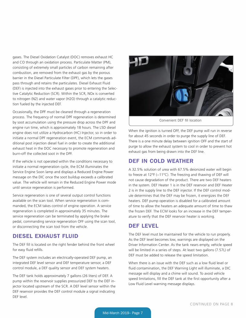
DIESEL EXHAUST FLUIDThe DEF fill is located on the right fender behind the front wheel
for easy fluid refills.
The DEF system includes an electrically-operated DEF pump, an
integrated DEF level sensor and DEF temperature sensor, a DEF
control module, a DEF quality sensor and DEF system heaters.
The DEF tank holds approximately 7 gallons (26 liters) of DEF. A
pump within the reservoir supplies pressurized DEF to the DEF in-
jector located upstream of the SCR. A DEF level sensor within the
DEF reservoir provides the DEF control module a signal indicating
DEF level.
When the ignition is turned OFF, the DEF pump will run in reverse
for about 45 seconds in order to purge the supply line of DEF.
There is a one minute delay between ignition OFF and the start of
purge to allow the exhaust system to cool in order to prevent hot
exhaust gas from being drawn into the DEF line.
DEF IN COLD WEATHERA 32.5% solution of urea with 67.5% deionized water will begin
to freeze at 12°F (−11°C). The freezing and thawing of DEF will
not cause degradation of the product. There are two DEF heaters
in the system. DEF Heater 1 is in the DEF reservoir and DEF Heater
2 is in the supply line to the DEF injector. If the DEF control mod-
ule determines that the DEF may be frozen, it energizes the DEF
heaters. DEF pump operation is disabled for a calibrated amount
of time to allow the heaters an adequate amount of time to thaw
the frozen DEF. The ECM looks for an increase in the DEF temper-
ature to verify that the DEF reservoir heater is working.
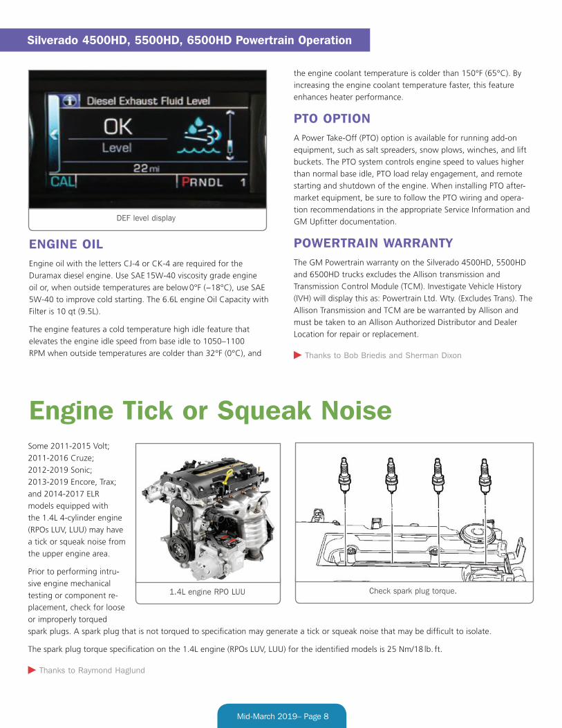
DEF LEVELThe DEF level must be maintained for the vehicle to run properly.
As the DEF level becomes low, warnings are displayed on the
Driver Information Center. As the tank nears empty, vehicle speed
will be limited in a series of steps. At least two gallons (7.57L) of
DEF must be added to release the speed limitation.
When there is an issue with the DEF such as a low fluid level or
fluid contamination, the DEF Warning Light will illuminate, a DIC
message will display and a chime will sound. To avoid vehicle
speed limitations, fill the DEF tank at the first opportunity after a
Low Fluid Level warning message displays.
Convenient DEF fill location
CONTINUED ON PAGE 8
Page 8
Mid-March 2019– Page 8
ENGINE OILEngine oil with the letters CJ-4 or CK-4 are required for the
Duramax diesel engine. Use SAE 15W-40 viscosity grade engine
oil or, when outside temperatures are below 0°F (−18°C), use SAE
5W-40 to improve cold starting. The 6.6L engine Oil Capacity with
Filter is 10 qt (9.5L).
The engine features a cold temperature high idle feature that
elevates the engine idle speed from base idle to 1050–1100
RPM when outside temperatures are colder than 32°F (0°C), and
the engine coolant temperature is colder than 150°F (65°C). By
increasing the engine coolant temperature faster, this feature
enhances heater performance.
PTO OPTIONA Power Take-Off (PTO) option is available for running add-on
equipment, such as salt spreaders, snow plows, winches, and lift
buckets. The PTO system controls engine speed to values higher
than normal base idle, PTO load relay engagement, and remote
starting and shutdown of the engine. When installing PTO after-
market equipment, be sure to follow the PTO wiring and opera-
tion recommendations in the appropriate Service Information and
GM Upfitter documentation.
POWERTRAIN WARRANTYThe GM Powertrain warranty on the Silverado 4500HD, 5500HD
and 6500HD trucks excludes the Allison transmission and
Transmission Control Module (TCM). Investigate Vehicle History
(IVH) will display this as: Powertrain Ltd. Wty. (Excludes Trans). The
Allison Transmission and TCM are be warranted by Allison and
must be taken to an Allison Authorized Distributor and Dealer
Location for repair or replacement.
Thanks to Bob Briedis and Sherman Dixon
Silverado 4500HD, 5500HD, 6500HD Powertrain Operation
DEF level display
Some 2011-2015 Volt;
2011-2016 Cruze;
2012-2019 Sonic;
2013-2019 Encore, Trax;
and 2014-2017 ELR
models equipped with
the 1.4L 4-cylinder engine
(RPOs LUV, LUU) may have
a tick or squeak noise from
the upper engine area.
Prior to performing intru-
sive engine mechanical
testing or component re-
placement, check for loose
or improperly torqued
spark plugs. A spark plug that is not torqued to specification may generate a tick or squeak noise that may be difficult to isolate.
The spark plug torque specification on the 1.4L engine (RPOs LUV, LUU) for the identified models is 25 Nm/18 lb. ft.
Thanks to Raymond Haglund
Engine Tick or Squeak Noise
1.4L engine RPO LUU Check spark plug torque.
Page 9
Mid-March 2019– Page 9
A lack of engine performance along with an incorrect low fuel
range display may be found on some 2017-2018 Acadia, Enclave,
Traverse and XT5 models equipped with the 3.6L V6 engine (RPOs
LFY, LGX) and all-wheel-drive (AWD). The following DTCs also
may be set in the Engine Control Module (ECM):
• P018B: Fuel Pressure Sensor Performance
• P2635: Fuel Pump Flow Performance
• P0461: Fuel Level Sensor 1 Performance
• P0462: Fuel Level Sensor 1 Circuit Low Voltage
• P0463: Fuel Level Sensor 1 Circuit High Voltage
• P0464: Fuel Level Sensor 1 Circuit Intermittent
• P2066: Fuel Level Sensor 2 Performance
• P2067: Fuel Level Sensor 2 Circuit Low Voltage
• P2068: Fuel Level Sensor 2 Circuit High Voltage
These conditions may be caused by a partially or completely
blocked port on the primary in-tank fuel pump module transfer
jet manifold. The blockage of the port inhibits the suction to the
fuel transfer line, which leads to an inability to transfer fuel from
the secondary side on fuel tanks of AWD models.
AWD models have a fuel tank with a saddle configuration in
order to provide space for the driveshaft through the center area
of the fuel tank. Because of the saddle shape of the tank, two
fuel tank fuel pump modules are required. Fuel is drawn from the
secondary side of the fuel tank, through the fuel transfer pipe, to
the primary side of the fuel tank.
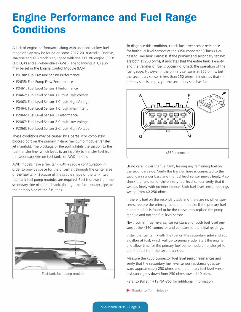
To diagnose this condition, check fuel lever sensor resistance
for both fuel level sensors at the x350 connector (Chassis Har-
ness to Fuel Tank Harness). If the primary and secondary sensors
are both at 250 ohms, it indicates that the entire tank is empty
and the transfer of fuel is occurring. Check the operation of the
fuel gauge. However, if the primary sensor is at 250 ohms, but
the secondary sensor is less than 250 ohms, it indicates that the
primary side is empty, yet the secondary side has fuel.
Using care, lower the fuel tank, leaving any remaining fuel on
the secondary side. Verify the transfer hose is connected to the
secondary sender base and the fuel level sensor moves freely. Also
check the function of the primary fuel level sender verify that it
sweeps freely with no interference. Both fuel level sensor readings
sweep from 40-250 ohms.
If there is fuel on the secondary side and there are no other con-
cerns, replace the primary fuel pump module. If the primary fuel
pump module is found to be the cause, only replace the pump
module and not the fuel level sensor.
Next, confirm fuel level sensor resistance for both fuel level sen-
sors at the x350 connector and compare to the initial readings.
Install the fuel tank (with the fuel on the secondary side) and add
a gallon of fuel, which will go to primary side. Start the engine
and allow time for the primary fuel pump module transfer jet to
pull the fuel from the secondary side.
Measure the x350 connector fuel level sensor resistances and
verify that the secondary fuel level sensor resistance goes to-
ward approximately 250 ohms and the primary fuel level sensor
resistance goes down from 250 ohms toward 40 ohms.
Refer to Bulletin #18-NA-365 for additional information.
Thanks to Tom Holecek
Engine Performance and Fuel Range Conditions
Fuel tank fuel pump module
x350 connector
Page 10
Mid-March 2019– Page 10
The infotainment system may display a “Navigation service has
expired.” message on some 2018-2019 Regal, ATS, CTS, XTS,
Terrain; 2019 CT6, XT4, Blazer, Camaro, Colorado, Equinox,
Malibu, Silverado, Volt, Canyon and Sierra models equipped with
navigation radios (RPOs IOU, IOT). If the navigation service is
still active, a “Navigation services is going to expire in XX days.”
message may appear. No DTCs will be set.
The navigation system is designed to alert owners that their
Connected Navigation service subscription or trial period is expir-
ing so that they will be able to renew the subscription. If owners
elect not to renew the subscription, the message also serves as
an alert as to why the system may operate differently than it did
when Connected Navigation services were active.
If the Connected Navigation services are expired, system opera-
tion will be limited to data stored locally in the SD card map data.
Connected Navigation service provides access to cloud-based
traffic and Point of Interest (POI) updates that may not be stored
locally in the SD card.
While the reminder messages are meant to be informative, the
frequency of the message may be occurring too often. In some
cases, the messages may appear every ignition cycle.
If the messages appear too frequently, verify that the navigation
system operates properly and provides navigation guidance. If the
navigation system is not operating correctly, follow the appropri-
ate Service Information diagnostics.
If the navigation system is operating correctly, but the services
reminder message continues to display every ignition cycle,
confirm with the customer whether the Connected Navigation
services subscription through OnStar has been renewed.
SUBSCRIPTION RENEWEDIf the subscription has been renewed and the reminder message
appears each ignition cycle, select No on the reminder popup
to stop the message from occurring every ignition cycle. If the
package subscription was renewed prior to the current one ex-
piring, the message will still appear at its regularly scheduled
intervals. Expiration popups should still be expected at 30-day
and 3-day intervals. Instruct the customer to select No on the
reminder popup. After the current subscription expires and the
new one begins, a reminder popup should not be seen again until
approximately 30 days before the next subscription expiration
date.
SUBSCRIPTION EXPIREDIf the subscription has not been renewed and the reminder
message appears each ignition cycle, and the navigation system
is operating properly, determine if the customer wishes to renew
the subscription. The customer can contact OnStar to renew the
subscription. However, if the customer does not wish to renew
the subscription, perform the following procedure:
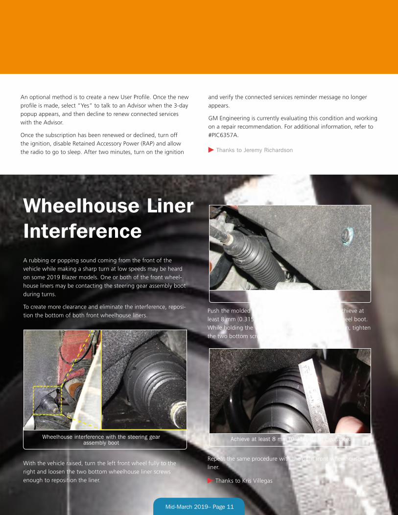
1. Perform a Return to Factory Defaults command through
the Settings > Vehicle menu on the infotainment system. A
message will be displayed to contact OnStar because the con-
nected services have expired.
2. Select “Yes” to talk with an Advisor, and then decline to renew
the service.
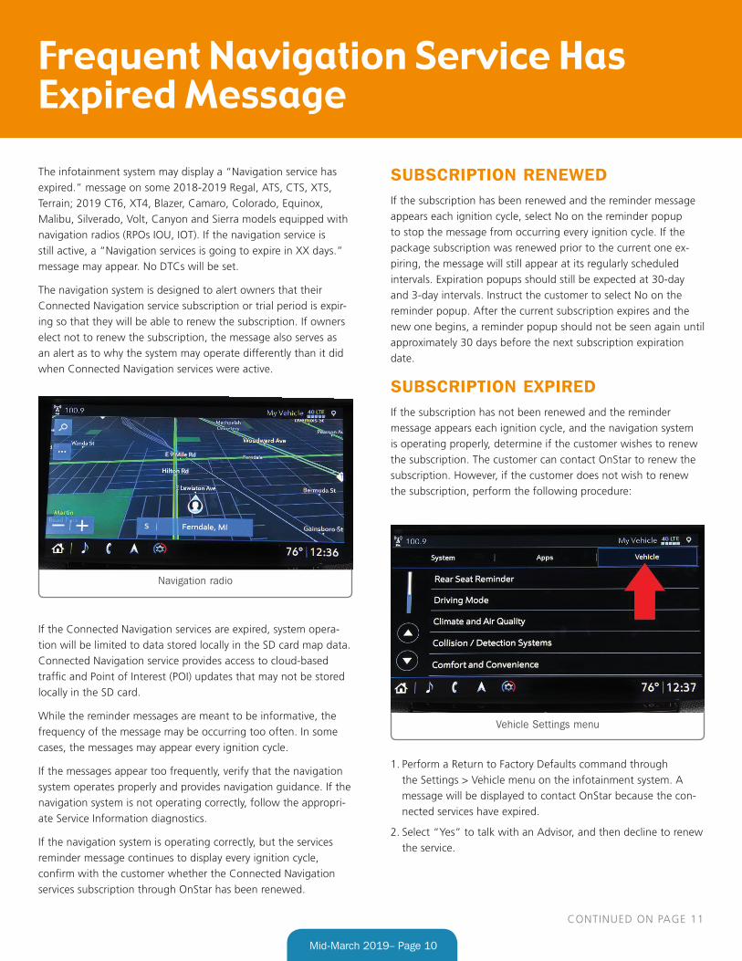
Navigation radio
Vehicle Settings menu
Frequent Navigation Service Has Expired Message
CONTINUED ON PAGE 11
Page 11
Mid-March 2019– Page 11
Wheelhouse Liner InterferenceA rubbing or popping sound coming from the front of the
vehicle while making a sharp turn at low speeds may be heard
on some 2019 Blazer models. One or both of the front wheel-
house liners may be contacting the steering gear assembly boot
during turns.
To create more clearance and eliminate the interference, reposi-
tion the bottom of both front wheelhouse liners.
With the vehicle raised, turn the left front wheel fully to the
right and loosen the two bottom wheelhouse liner screws
enough to reposition the liner.
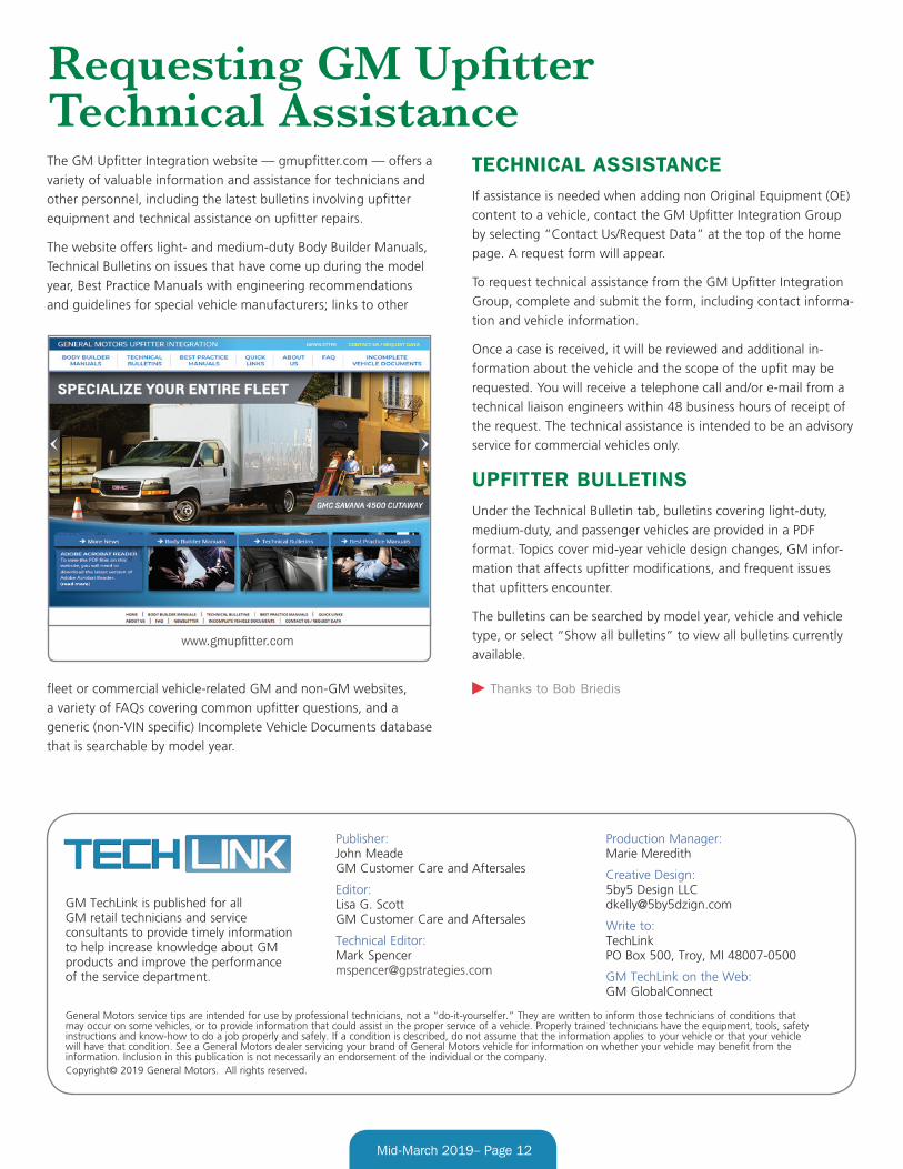
Push the molded bottom lip of the liner upward to achieve at
least 8 mm (0.315 in.) of clearance to the steering wheel boot.
While holding the wheelhouse liner in the new position, tighten
the two bottom screws to 22 lb.-in.
Repeat the same procedure with the right front wheelhouse
liner.
Thanks to Kris Villegas
Wheelhouse screws
Wheelhouse interference with the steering gear assembly boot
Achieve at least 8 mm (0.315 in.) of clearance.
An optional method is to create a new User Profile. Once the new
profile is made, select “Yes” to talk to an Advisor when the 3-day
popup appears, and then decline to renew connected services
with the Advisor.
Once the subscription has been renewed or declined, turn off
the ignition, disable Retained Accessory Power (RAP) and allow
the radio to go to sleep. After two minutes, turn on the ignition
and verify the connected services reminder message no longer
appears.
GM Engineering is currently evaluating this condition and working
on a repair recommendation. For additional information, refer to
#PIC6357A.
Thanks to Jeremy Richardson
Page 12
GM TechLink is published for all GM retail technicians and service consultants to provide timely information to help increase know ledge about GM products and improve the performance of the service department.
Publisher: John Meade GM Customer Care and Aftersales
Editor: Lisa G. Scott GM Customer Care and Aftersales
Technical Editor: Mark Spencer [email protected]
Production Manager: Marie Meredith
Creative Design: 5by5 Design LLC [email protected]
Write to: TechLink PO Box 500, Troy, MI 48007-0500
GM TechLink on the Web: GM GlobalConnect
General Motors service tips are intended for use by professional technicians, not a “do-it-yourselfer.” T hey are written to inform those technicians of conditions that may occur on some vehicles, or to provide information that could assist in the proper service of a vehicle. Properly trained technicians have the equipment, tools, safety instructions and know-how to do a job properly and safely. If a condition is described, do not assume that the information applies to your vehicle or that your vehicle will have that condition. See a General Motors dealer servicing your brand of General Motors vehicle for information on whether your vehicle may benefit from the information. Inclusion in this publication is not necessarily an endorsement of the individual or the company.Copyright© 2019 General Motors. All rights reserved.
Mid-March 2019– Page 12
The GM Upfitter Integration website — gmupfitter.com — offers a
variety of valuable information and assistance for technicians and
other personnel, including the latest bulletins involving upfitter
equipment and technical assistance on upfitter repairs.
The website offers light- and medium-duty Body Builder Manuals,
Technical Bulletins on issues that have come up during the model
year, Best Practice Manuals with engineering recommendations
and guidelines for special vehicle manufacturers; links to other
fleet or commercial vehicle-related GM and non-GM websites,
a variety of FAQs covering common upfitter questions, and a
generic (non-VIN specific) Incomplete Vehicle Documents database
that is searchable by model year.
TECHNICAL ASSISTANCEIf assistance is needed when adding non Original Equipment (OE)
content to a vehicle, contact the GM Upfitter Integration Group
by selecting “Contact Us/Request Data” at the top of the home
page. A request form will appear.
To request technical assistance from the GM Upfitter Integration
Group, complete and submit the form, including contact informa-
tion and vehicle information.
Once a case is received, it will be reviewed and additional in-
formation about the vehicle and the scope of the upfit may be
requested. You will receive a telephone call and/or e-mail from a
technical liaison engineers within 48 business hours of receipt of
the request. The technical assistance is intended to be an advisory
service for commercial vehicles only.
UPFITTER BULLETINSUnder the Technical Bulletin tab, bulletins covering light-duty,
medium-duty, and passenger vehicles are provided in a PDF
format. Topics cover mid-year vehicle design changes, GM infor-
mation that affects upfitter modifications, and frequent issues
that upfitters encounter.
The bulletins can be searched by model year, vehicle and vehicle
type, or select “Show all bulletins” to view all bulletins currently
available.
Thanks to Bob Briedis
Requesting GM Upfitter Technical Assistance
www.gmupfitter.com