Middletown - Norwalk Transmission Project Technical Description of VSC HVDC Converter and Cable Technology Issued: October 1, 2004 Prepared for Northeast Utilities Submitted by: ABB Power Technologies AB Power Systems DC Ludvika Sweden
Transcript
Middletown - Norwalk Transmission Project Technical Description of VSC HVDC Converter and
Cable Technology
Issued: October 1, 2004 Prepared for Northeast Utilities Submitted by:
ABB Power Technologies AB Power Systems DC
Ludvika Sweden
Legal Notice This document has been prepared by ABB Inc. and ABB Power Technologies AB. Neither ABB Power Technologies AB nor ABB Inc., nor any person or persons acting on behalf of either party: (i) makes any warranty or representation, expressed or implied, with respect to the use of any information contained in this report, or that the use of any information, apparatus, method, or process disclosed in this report may not infringe privately owned rights, or (ii) assumes any liabilities with respect to the use of or for damages resulting from the use of any information, apparatus, method, or process disclosed in this document.
i
Middletown – Norwalk Transmission Project Technical Description of VSC HVDC Converter and Cable Technology
Executive Summary ABB has been asked by Northeast Utilities (NU) to conduct a study of the feasibility of applying Voltage Source Converter (VSC) technology for the proposed electric transmission line between Middletown, Connecticut and Norwalk, Connecticut. NU has defined 13 criteria to be met from the proposed scheme with one of the most important criteria being to “improve the point of the first system resonance to 3rd harmonic or higher”. The studies conducted by ABB demonstrate that a 100% underground VSC based HVDC solution for Southwest Connecticut (SWCT) all the way from Middletown to Norwalk is technically feasible and accommodates all technical and operational criteria established by NU, the United Illuminating Company (UI), and the New England Independent System Operator (NE ISO). This is described in detail in a separate report by ABB Electric Systems Consulting entitled “Middletown – Norwalk Transmission Project, VSC HVDC System Feasibility Study”. This report describes the characteristics of VSC Converter and Cable technology and how this technology could be applied on the SWCT Project. Of particular importance for this project, apart from meeting all electrical system criteria, is the very compact design of the converters and the fact that the underground DC cable system will give very low magnetic fields. A number of schemes have been studied and existing building blocks and configurations have been used to the highest possible extent. All schemes discussed are built up with parallel independent systems providing increased security of supply since each system can operate independently from the others. The report also gives budgetary prices that show that the entire underground system with two or three cable systems from Middletown to Norwalk could be built for a total cost of $630 – 830 million US dollars (MUSD) depending on the chosen configuration. The approach with multiple systems also offers a possibility to build in stages thereby saving on the initial investment. The numbers include the cost of turnkey converters and cables, including an estimate of the cable installation. The report includes information on the cable laying method the price is based on.
ii
Table of contents 1 Underground Transmission Alternatives ............................................................1
1.1 Limitations of AC Cables Compared to DC Cables ....................................................... 1 1.2 Conventional HVDC Application Considerations.......................................................... 2
1.2.1 Reactive Power Compensation ............................................................................... 2 1.2.2 Relative System Strength........................................................................................ 2 1.2.3 Transient Performance ............................................................................................ 2 1.2.4 Power Reversal ....................................................................................................... 2
1.3 System Integration Advantages with HVDC Light ........................................................ 3 1.4 Controllability ................................................................................................................. 4 1.5 Southwest Connecticut Project DC Underground Transmission Alternatives ............... 7 1.6 Incremental System Expansion....................................................................................... 9
2 Main Circuit Configurations.............................................................................10 2.1 Simplified Single Line Diagram ................................................................................... 10 2.2 System Description ....................................................................................................... 10 2.3 Multiterminal Operation ............................................................................................... 11
3.2 HVDC Light Cable System Design .............................................................................. 14 3.2.1 General land cable design features ....................................................................... 14 3.2.2 Cable accessories for HVDC Light land cable system ......................................... 15
3.3 Physical Configuration of Installation in Duct Bank.................................................... 16 3.3.1 General criteria...................................................................................................... 16 3.3.2 Alternative 1, 3 x 370 MW ................................................................................... 17 3.3.3 Alternative 2, 2 x 530 MW ................................................................................... 17
3.4 Cable Thermal Design for Duct Banks......................................................................... 18 3.4.1 Electrical system requirements ............................................................................. 18 3.4.2 Assumed Installation Conditions .......................................................................... 18 3.4.3 Cable size and electrical parameters, Alternative 1, 370 MW.............................. 19 3.4.4 Cable size and electrical parameters, Alternative 2, 530 MW.............................. 20
3.5 Magnetic Field Profiles and Properties......................................................................... 21 3.5.1 Magnetic Field Standards and Requirements ....................................................... 21 3.5.2 Predicted magnetic field from the suggested HVDC cable installation. .............. 21
3.6 Cable Installation .......................................................................................................... 25 3.6.1 Comparison of installation requirements between HPFF cables and XLPE AC or HVDC Light cables............................................................................................................... 25 3.6.2 Comparison of installation requirements between DC cables and AC cables...... 26 3.6.3 Comments on direct burial installation ................................................................. 26 3.6.4 Cable jointing........................................................................................................ 27 3.6.5 Maintenance.......................................................................................................... 27 3.6.6 Summary of advantages and disadvantages between using HPFF, XLPE or HVDC Light cables for the Middletown – Norwalk Project ................................................ 28
3.7.1 Pre-location of fault .............................................................................................. 29 3.7.2 Fine-location of a fault.......................................................................................... 29 3.7.3 Repair time............................................................................................................ 30
3.8 Cable Testing ................................................................................................................ 30 3.8.1 Type testing and pre-qualification tests ................................................................ 30 3.8.2 Routine test ........................................................................................................... 31 3.8.3 Sample test ............................................................................................................ 31 3.8.4 After installation test............................................................................................. 31
4 Station Layouts and Footprint...........................................................................31 5 System Issues ....................................................................................................33
5.1 Reactive Power Compensation ..................................................................................... 33 5.2 Resonance and Transient Overvoltages ........................................................................ 33 5.3 AC System Voltage Support......................................................................................... 34
5.3.1 Steady State........................................................................................................... 34 5.3.2 Dynamic................................................................................................................ 34 5.3.3 Parallel Operation ................................................................................................. 35 5.3.4 Harmonics and Power Quality .............................................................................. 35
5.4 Integration of New Substations..................................................................................... 35 5.5 Integration of New Generation ..................................................................................... 36 5.6 Short Circuit Current Limitation................................................................................... 36 5.7 Subsynchronous Torsional Interaction Mitigation........................................................ 37
6.3 Security Constrained Economic Dispatch and Unit Commitment ............................... 38 6.4 Reliability, Availability and Maintenance .................................................................... 38
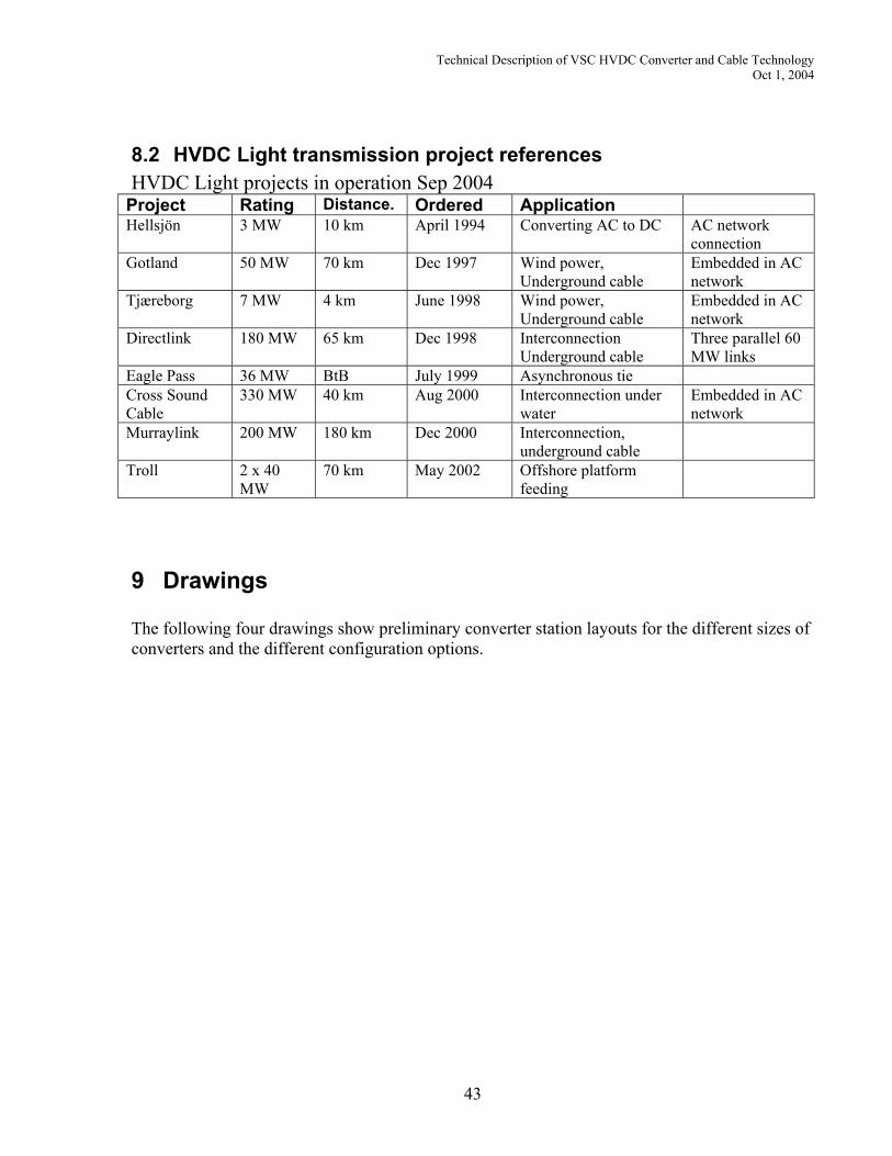
7 Price Estimates..................................................................................................39 8 References and Common Experience ...............................................................40
8.1 Cable Experience and References................................................................................. 40 8.1.1 HVDC Light references ........................................................................................ 40 8.1.2 Installation in ducts ............................................................................................... 40
Technical Description of VSC HVDC Converter and Cable Technology Oct 1, 2004
1 Underground Transmission Alternatives
1.1 Limitations of AC Cables Compared to DC Cables Underground high voltage power cables are composed of current-carrying conductors insulated from ground potential. Cables, like overhead transmission lines, exhibit certain physical properties based on the conductor characteristics and physical dimensions of the transmission circuit. When carrying alternating current, these physical properties affect the power flow and the voltage profile due to their associated electromagnetic and electrostatic fields. With alternating current (AC) transmission, the electrostatic field must be continuously charged requiring a certain portion of its current carrying capacity for charging the cable to its operating voltage level. With AC cable transmission, the charging component is especially high due to the greater capacitance per unit length of the AC cables. This limits the effective transmission distance and requires supplemental compensation to avoid too high voltage during light loading conditions. With direct current (DC), however, these physical properties have no impact on power flow, voltage profile or transmission distance.
• Charging current consumes capacity cumulatively with distance, e.g., 40 kilometer (km) 230 kilovolt (kV) cable requires 450 Ampere (A) charging current
• Capacity diminishes with distance limiting maximum effective distance
• Three cables per circuit • Higher losses • Cable can become overloaded following
contingencies or uneven voltage profiles. • Induced currents may require cross
bonding equipment at joint bays. • Permissible levels of electro-magnetic field
strength are significantly lower for time-varying fields due to their induction effect.
AC Cable - Charging Current Reduces Power Transfer Capability
• No charging current • No distance limitation • All capacity available for power transmission• Two cables per bipolar transmission circuit • Lower losses • Controlled power flow – cable can not
become overloaded • No impact from induced currents • Permissible levels of static electro-magnetic
field strength are significantly higher since there is no induction effect and magnetic fields are similar to that of the earth itself.
DC Cable - Full Capability Available for Power Transmission
1
Technical Description of VSC HVDC Converter and Cable Technology Oct 1, 2004
1.2 Conventional HVDC Application Considerations
1.2.1 Reactive Power Compensation Conventional high voltage direct current (HVDC) transmission uses line-commutated, current-source converters. Each converter consumes reactive power in the order of 50% of its power rating. For example, a 1000 megawatt (MW) converter demands about 500 megaVAR (MVAR) of reactive power at full load. This reactive power demand must be compensated at each HVDC terminal. Part (about 35%) of this compensation comes from harmonic filters, which are required for meeting power quality standards while the rest must come from shunt or series capacitors incorporated into the converter station design. Since converter reactive power demand is a function of power transmitted, shunt compensation elements must be switched with load to minimize the reactive power exchange with the network and help keep the voltage within desired limits. This concentration of reactive power compensation impacts station space requirements, dynamic overvoltage and parallel resonance frequency with the ac network.
HarmonicFilters
Shunt Banks
1,0
0,13
0,5
filter
converter
Id
Q
Classic
HarmonicFilters
Shunt Banks
1,0
0,13
0,5
filter
converter
Id
Q
Classic
HarmonicFilters
Shunt Banks
1,0
0,13
0,5
filter
converter
Id
Q
Classic
1,0
0,13
0,5
filter
converter
Id
Q
Classic
unbalanceunbalanceunbalanceunbalance
Figure 1 Conventional HVDC Reactive Power Compensation
1.2.2 Relative System Strength Power transfer with conventional HVDC transmission is limited to a level equal to about half of the ac system short circuit capacity. If, under system contingencies, the relative short circuit capacity falls below this level, DC power transfer must be limited.
1.2.3 Transient Performance Conventional HVDC transmission is subject to commutation failure for inverter ac network system faults resulting in a momentary “glitch” in power transfer. Normally this has little impact on system stability but, with multiple inverters relatively close to one another, commutation failure performance may be decisive in determining the power transfer limitations.
1.2.4 Power Reversal Power reversal in a conventional HVDC scheme is accomplished by polarity reversal. With two terminal systems, this is accomplished electronically by a coordinated change in polarity at each terminal. With multi-terminal systems,
2
Technical Description of VSC HVDC Converter and Cable Technology Oct 1, 2004
however, an independent change of power direction at one terminal while maintaining the same power direction at the other terminals must be accomplished via DC polarity reversing switches at the terminal whose power direction is to be reversed
1.3 System Integration Advantages with HVDC Light The attributes of HVDC Light voltage source converters allow for simpler AC system integration. These attributes include the following:
• Independent, continuous control of active and reactive power at each terminal • Steady state reactive power capability can be used for voltage control • Independent control of reactive power at every terminal while maintaining full
DC voltage for efficient transmission operation • Dynamic reactive power reserve capability from the voltage source converters
for contingency voltage support the interconnected AC system • Less filtering requirements, i.e., 15 to 20% of rated power, • No requirement for switching filters or shunt capacitor banks for reactive power
compensation with changes in power transfer • No inherent fault current contribution to increase circuit breaker interrupting
duty. Fault current contribution is naturally limited to maximum load current but can be reduced even further during faults by fast acting control.
The reactive power capability of the VSC converter adds another dimension to its overall controllability. The combination of active and reactive power control at each terminal gives it the attributes of a virtual generator at each point of power delivery. This reduces the investment, which would be otherwise required for local voltage support, e.g., mechanically switched shunt reactors or capacitors, Static Var Compensators (SVC) or STATCOMS. The advantages of HVDC Light technology to help support the AC networks in which they are embedded have been utilized and demonstrated for several HVDC Light projects. These projects are Gotland HVDC Light, Tjaereborg, Direct Link and Cross Sound Cable. The following figure illustrates the real power, P, and reactive power, Q, capability of the HVDC Light converter terminal, measured at the interconnection point, as a function of AC system voltage. The capacitive reactive power capability increases with decreasing voltage when it is needed most. Similarly, the inductive reactive power capability increases with increasing voltage when it is needed most. For a given AC system voltage the converter can be operated at any point within its respective circle.
3
Technical Description of VSC HVDC Converter and Cable Technology Oct 1, 2004
Figure 2 Converter Active Power (P) and Reactive Power (Q) Capability
1.4 Controllability In general, power flow on AC transmission is not directly controllable. Transmission flows are determined by scheduling generation to meet demand and operational security constraints. Generation scheduling is by security constrained economic dispatch, SCED, and security constrained unit commitment, SCUC. In some cases, devices that alter the power flow distribution are incorporated into the AC network. For example, series compensation is often used to increase the loading on EHV overlaying transmission and to help unload parallel lower voltage underlying transmission. Another common example is the use of phase angle regulators to buck the flow on circuits, which tend to become overloaded or boost the flow on circuits, which tend to be underutilized under economic dispatch. Flow control helps to increase the utilization of transmission assets and reduce the need for fully redundant transmission capacity. When used such devices are controlled by system operations and usually integrated into the SCED and SCUC programs. With respect to controllability, use of HVDC in an integrated network application is not much different than use of a phase angle regulator. Increase of network transfer capacity can be by means of AC transmission, DC transmission or a combination of the two. The fundamental difference is that DC transmission is directly controllable, and AC transmission is not. Therefore, DC transmission must be told what to do or how to react whereas AC transmission merely responds to external events, i.e., changes in generation dispatch or contingencies such as loss of generation or transmission. Direct transmission controllability offers an added degree for freedom to maximize network operating efficiency or pre-position the network to better withstand contingencies. This added operational flexibility is
4
Technical Description of VSC HVDC Converter and Cable Technology Oct 1, 2004
accompanied by what may be thought of as the associated burden of control either by operator intervention or by automatic control functions. In many cases, however, there may be no need for any automatic control functions. In other cases, simple local control functions can be very beneficial. There is a wealth of experience in the operation and control of HVDC links integrated and embedded into AC networks. This knowledge and experience base is portable and directly transferable to new DC transmission schemes such as the alternatives suggested for the Southwest Connecticut Project regardless of converter type selected. The application with HVDC Light converters is even more straightforward because of the relative ease of reactive power coordination; complete absence of emergency ground current return operation and reduced inter-terminal coordination. With help from the following figure, a number of examples from various North American HVDC projects serve to illustrate a number of principal control concepts.
Bipole
L1
L2
L3
L4
L5
L6,7
P1
P2
G1
G2
B2B1
C1
C2
Bipole
L1
L2
L3
L4
L5
L6,7
P1
P2
G1
G2
B2B1
C1
C2
Figure 3 HVDC reference scheme
Pole Loss Compensation – The HVDC link is operated in bipolar power control mode wherein a single set point or power order is given by system dispatch to schedule the desired power transfer. Normally, the power flow is equal and balanced on the two poles, P1 and P2. If, however, there is an outage of one pole the other pole is used up to its rated capacity to compensate for the loss. Any residual shortfall will flow on parallel AC lines L6 and L7. Overload management takes into account any overload capacity, which may exist, on the healthy pole. The control function is entirely local. It serves to make the bipolar DC line act like a double circuit AC line. Bipolar Power Control with Pole Loss Compensation is used on the following HVDC Projects operating in parallel with AC transmission: Pacific Intertie, Square Butte, CU, Intermountain, and Quebec – New England. The same concept can be extended to multiple bipoles such as Nelson River, Itaipu and Direct Link. In these cases loss of a pole or bipole can be automatically compensated on the remaining poles or bipole. Converter Loss Compensation – Converter loss compensation covers loss of a parallel converter such as C1 on the same circuit at either a local station or at a remote tap. In this case, there is a need for some inter-terminal coordination to maintain a current
5
Technical Description of VSC HVDC Converter and Cable Technology Oct 1, 2004
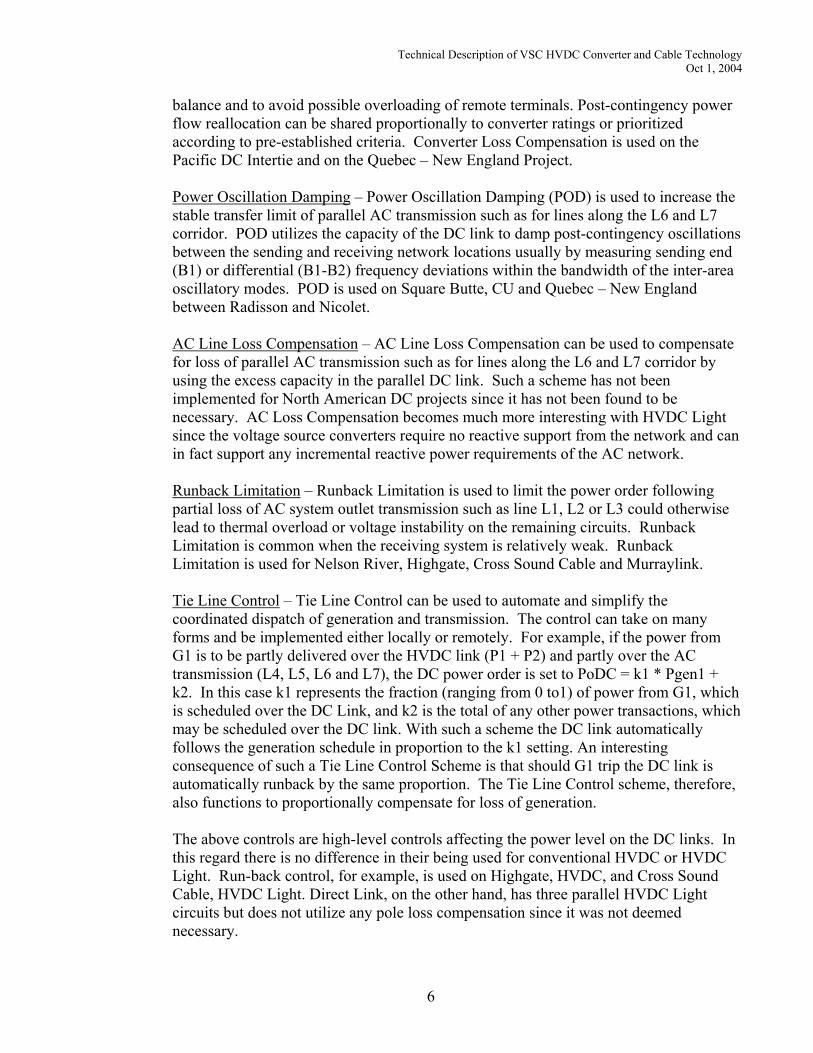
balance and to avoid possible overloading of remote terminals. Post-contingency power flow reallocation can be shared proportionally to converter ratings or prioritized according to pre-established criteria. Converter Loss Compensation is used on the Pacific DC Intertie and on the Quebec – New England Project. Power Oscillation Damping – Power Oscillation Damping (POD) is used to increase the stable transfer limit of parallel AC transmission such as for lines along the L6 and L7 corridor. POD utilizes the capacity of the DC link to damp post-contingency oscillations between the sending and receiving network locations usually by measuring sending end (B1) or differential (B1-B2) frequency deviations within the bandwidth of the inter-area oscillatory modes. POD is used on Square Butte, CU and Quebec – New England between Radisson and Nicolet. AC Line Loss Compensation – AC Line Loss Compensation can be used to compensate for loss of parallel AC transmission such as for lines along the L6 and L7 corridor by using the excess capacity in the parallel DC link. Such a scheme has not been implemented for North American DC projects since it has not been found to be necessary. AC Loss Compensation becomes much more interesting with HVDC Light since the voltage source converters require no reactive support from the network and can in fact support any incremental reactive power requirements of the AC network. Runback Limitation – Runback Limitation is used to limit the power order following partial loss of AC system outlet transmission such as line L1, L2 or L3 could otherwise lead to thermal overload or voltage instability on the remaining circuits. Runback Limitation is common when the receiving system is relatively weak. Runback Limitation is used for Nelson River, Highgate, Cross Sound Cable and Murraylink. Tie Line Control – Tie Line Control can be used to automate and simplify the coordinated dispatch of generation and transmission. The control can take on many forms and be implemented either locally or remotely. For example, if the power from G1 is to be partly delivered over the HVDC link (P1 + P2) and partly over the AC transmission (L4, L5, L6 and L7), the DC power order is set to PoDC = k1 * Pgen1 + k2. In this case k1 represents the fraction (ranging from 0 to1) of power from G1, which is scheduled over the DC Link, and k2 is the total of any other power transactions, which may be scheduled over the DC link. With such a scheme the DC link automatically follows the generation schedule in proportion to the k1 setting. An interesting consequence of such a Tie Line Control Scheme is that should G1 trip the DC link is automatically runback by the same proportion. The Tie Line Control scheme, therefore, also functions to proportionally compensate for loss of generation. The above controls are high-level controls affecting the power level on the DC links. In this regard there is no difference in their being used for conventional HVDC or HVDC Light. Run-back control, for example, is used on Highgate, HVDC, and Cross Sound Cable, HVDC Light. Direct Link, on the other hand, has three parallel HVDC Light circuits but does not utilize any pole loss compensation since it was not deemed necessary.
6
Technical Description of VSC HVDC Converter and Cable Technology Oct 1, 2004
1.5 Southwest Connecticut Project DC Underground Transmission Alternatives A number of different HVDC underground transmission alternatives are considered for Phase II of the Southwest Connecticut Project between Middletown and Norwalk. Only alternatives with underground transmission are considered. HVDC Light technology is used in all cases due to its relative ease of system integration and beneficial attributes. Alternatives include multiple two-terminal HVDC circuits, multi-terminal HVDC circuits and combinations of AC and HVDC underground circuits. Two different base terminal power ratings are considered, 370 MW and 530 MW, delivered to the receiving AC network. Although the higher rating has not been placed in service yet it is a natural progression of the development built upon a firm experience base. First of all, the cable voltage in all cases is ± 150 kV, for a bipolar voltage of 300 kV. This utilizes the same valve stack design as for Murraylink and Cross Sound Cable. Second, the converter current capacity will be increased by including more parallel components within the same valve position. The position design and heat sink is also the same as it was originally designed to accommodate the higher number of parallel components. With the larger rating fewer circuits are required for each segment. The figures below show the different alternatives. Certain practical system application aspects are addressed in this report while other performance aspects are addressed in a separate report prepared by ABB Electric Systems Consulting.
Norwalk Beseck
Singer
Devon
Norwalk Beseck
Singer
Devon
Figure 4 Option 1
Norwalk Beseck
Singer Devon
Norwalk Beseck
Singer Devon Figure 5 Option 2
7
Technical Description of VSC HVDC Converter and Cable Technology Oct 1, 2004
Norwalk Beseck
Singer Devon
Norwalk Beseck
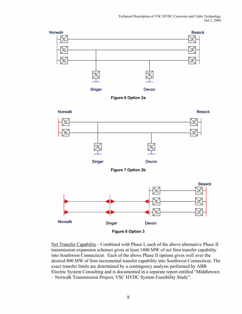
Singer Devon Figure 6 Option 2a
Norwalk Beseck
Singer Devon
Norwalk Beseck
Singer Devon Figure 7 Option 2b
Norwalk
Beseck
Singer DevonNorwalk
Beseck
Singer Devon Figure 8 Option 3
Net Transfer Capability - Combined with Phase I, each of the above alternative Phase II transmission expansion schemes gives at least 1400 MW of net firm transfer capability into Southwest Connecticut. Each of the above Phase II options gives well over the desired 800 MW of firm incremental transfer capability into Southwest Connecticut. The exact transfer limits are determined by a contingency analysis performed by ABB Electric System Consulting and is documented in a separate report entitled “Middletown – Norwalk Transmission Project, VSC HVDC System Feasibility Study”.
8
Technical Description of VSC HVDC Converter and Cable Technology Oct 1, 2004
When these DC alternatives are compared to the Phase II AC alternative, some principal differences stand out.
• Loadability - The DC alternatives can be loaded up to 100% of their rating upon demand since they are controllable. With the Phase II AC alternative, however, loading of new AC circuits depends on the load distribution, the generation schedule, and the relative AC network impedances. Shorter parallel paths will carry a heavier share of the transfer whereas longer parallel paths will be underutilized.
• Overload – The DC cables cannot be overloaded because the converter terminals control the power through them. Any overload capability available, e.g., load ambient overload, can be safely utilized since it can be managed by the converter controls. There is no risk of post-contingency overload of the cables with real or reactive power due to loss of parallel circuits, trip of downstream generation or partial AC voltage collapse in SWCT.
• Utilization – Utilization of the DC transmission can be controlled and balanced with other parallel circuits to minimize losses or pre-position the network to better withstand contingencies. In the case of cable utilization, DC cables do not need to have reserve thermal capacity due to charging current, as do AC cables.
• Redundancy – The DC alternatives suggested provide multiple circuits between Beseck and East Devon instead of just the one 1200 MVA circuit included in the proposed AC scheme. This means that the loss of one of these circuits would have less of an impact on the parallel or underlying transmission and fewer additional reinforcements
• Other – There are other issues, e.g., short circuit contribution, space requirements, impact on network low-order resonances, associated with application of HVDC to solve the transmission needs of Southwestern Connecticut. These are addressed in subsequent sections.
1.6 Incremental System Expansion Since the DC alternatives suggested cover several transmission segments with parallel circuits, the opportunity exists to stage the transmission capacity additions incrementally to better match the growth in system requirements. This permits spreading out the investment. With the proposed use of duct banks for the cables construction disruption can be minimized either by installing sufficient duct bank capacity initially or by staging narrower or shallower duct banks along different paths at different times. There are many examples where HVDC capacity additions have been staged with series converters, parallel converters, taps or parallel circuits being added at different times. These include the Pacific DC Intertie, Nelson River, Gotland, New Zealand, Quebec-New England and Direct Link. With some projects additions have been made many years later without it having been incorporated into the original design. With other projects the staging has been compressed and been planned as part of the original design. Such is the case for the Direct Link HVDC Light project.
9
Technical Description of VSC HVDC Converter and Cable Technology Oct 1, 2004
2 Main Circuit Configurations
2.1 Simplified Single Line Diagram
AC Harmonic Filters
DC Capacitors(Voltage Sources)
Converter Valves
Phase Reactors
Cables
AC Transformers, breakers/disconnectors
AC Harmonic FiltersAC Harmonic Filters
DC Capacitors(Voltage Sources)DC Capacitors(Voltage Sources)
Converter ValvesConverter Valves
Phase ReactorsPhase Reactors
CablesCables
AC Transformers, breakers/disconnectorsAC Transformers, breakers/disconnectors Figure 9 Typical HVDC Light converter station
2.2 System Description HVDC transmission with voltage source converter (VSC) technology has certain attributes, which can be beneficial to overall system performance. HVDC Light™ technology developed by ABB employs voltage source converters (VSC) with series-connected insulated gate bipolar transistor (IGBT) valves controlled with pulse width modulation (PWM). VSC converters used for power transmission permit continuous and independent control of real and reactive power. Reactive power control is also independent of that at any other terminal. Reactive power control can be used for dynamic voltage regulation to support the interconnecting AC system following contingencies. This capability can increase the overall transfer levels. Forced commutation with VSC even permits black start, i.e., the converter can be used to synthesize a balanced set of three phase voltages much like a synchronous machine. VSC-based HVDC transmission utilizes several important technological developments: • High voltage valves with series-connected IGBTs • Compact, dry, HVDC capacitors • High capacity control system • Solid dielectric DC cable A special gate unit and voltage divider across each IGBT maintain an even voltage distribution across the series connected IGBTs. The gate unit not only maintains proper
10
Technical Description of VSC HVDC Converter and Cable Technology Oct 1, 2004
voltage sharing within the valve during normal switching conditions but also during system disturbances and fault conditions. A reliable short circuit failure mode exists for individual IGBTs within each valve position.
Depending on the converter rating, series-connected IGBT valves are arranged in either a three-phase two-level or three-level bridge. In three-level converters, IGBT valves may also be used in place of diodes for neutral point clamping. Each IGBT position is individually controlled and monitored via fiber optics and equipped with integrated anti-parallel, freewheeling diodes. Each IGBT has a rated voltage of 2.5 kV with rated currents up to 1500 A. Each VSC station is built up with modular valve housings that are constructed to shield electromagnetic interference (EMI). The valves are cooled with circulating water and water to air heat exchangers. PWM switching frequencies for the VSC typically range between 1-2 kHz depending on the converter topology, system frequency and specific application. Each VSC is effectively mid-point grounded and coupled to the AC bus via phase reactors and a power transformer with intermediary shunt AC filters. The AC filters are tuned to multiples of the switching frequency. This arrangement minimizes harmonic content and avoids DC voltage stresses in the transformer, which allows use of a standard AC power transformer for matching the AC network voltage to the converter AC voltage necessary to produce the desired DC transmission voltage. DC capacitors are used across the DC side of the VSC. For transmission applications there may also be DC filters and a zero-sequence blocking reactor. The filters and zero-sequence reactor are used to mitigate interference on any metallic telephone circuits that run adjacent to the DC cables. The total capacitance of the pole to ground DC capacitors vary with the application.
2.3 Multi-terminal Operation Some of the suggested DC schemes involve multi-terminal operation of the DC links. Multi-terminal HVDC operation is used on the Pacific DC Intertie (parallel converters at its terminals), Quebec-New England Phase II and on Nelson River I and II during emergency conditions (loss of parallel transmission line). All of these systems use conventional HVDC converters. There are both similarities and differences between multi-terminal operation of HVDC and HVDC Light. These are summarized below: • Power Reversal – Power reversal with conventional HVDC is by controlled DC
polarity reversal whereas with HVDC Light it is by controlled DC current reversal. With a multi-terminal scheme this difference is significant since, with HVDC, power reversal at one tap cannot be accomplished without affecting the other terminals unless DC side polarity reversal switches are used. Polarity reversal switching is not required with multi-terminal HVDC Light and power reversal can be ordered directly.
• Pole Unbalance - A conventional HVDC bipolar scheme is double circuit with unbalance current flowing through a metallic neutral or through earth via ground electrodes. Normally the unbalance current is zero. Under emergency conditions, i.e., loss of a pole, however, unbalance current is high and flows through the neutral
11
Technical Description of VSC HVDC Converter and Cable Technology Oct 1, 2004
/ earth until the pole is either returned to operation or until metallic return is initiated. With conventional HVDC multi-terminal configurations unbalance currents can occur for loss of individual converters or taps and metallic return operation is more complicated. The HVDC Light schemes suggested, although bipolar, consist of single circuits with no unbalance currents either normally or following contingencies. No metallic neutral or metallic return switching schemes are required. Operation is simpler.
• Kirchoff’s Law – With a multi-terminal system one terminal controls the DC voltage just as with a two terminal scheme. The other terminals control their power (current in a constant voltage scheme). Whether HVDC or HVDC Light, net current out must equal net current in (Kirchoff’s Law) both in steady-state operation or following loss of a converter. This current order balance must be maintained by the control system in order to keep the remaining stations in operation after an outage. Control schemes, which manage the current order balance, have been developed and are in use in the Quebec-New England project. These control concepts are directly applicable to multi-terminal HVDC Light schemes. Inter-station coordination, however, is simpler due to the fundamental way in which HVDC Light is controlled with prioritized multimode regulators.
• Power Flow Reallocation - Converter loss compensation covers loss of a parallel converter on the same circuit. There is a need for some inter-terminal coordination to maintain a current balance and to avoid possible overloading of remote terminals. Post-contingency power flow reallocation can be shared proportionally to converter ratings or prioritized according to pre-established criteria. Converter Loss Compensation is used on the Pacific DC Intertie and on the Quebec – New England Project. Control functions developed for these conventional schemes are directly transferable to HVDC Light schemes but can be simplified.
• Protective Isolation – Just as with taps on AC lines, isolation of faults with a DC tap involves action at remote line terminals and local switching to isolate the tap in order to restore the remainder of the circuit to operation. This requires inter-station coordination. Without isolation switches and protective coordination a fault at the tap will take out the entire circuit.
• Dynamic Performance – Small parallel taps on conventional HVDC multi-terminal systems, especially those connected at relatively weak locations in the AC network, can unduly influence the dynamic performance of the entire HVDC link during local AC system faults. This is because the sudden reduction in AC commutating voltage at the affected station can result in a commutation failure, which momentarily collapses the DC voltage on the entire circuit. This temporary DC voltage collapse results in a momentary ‘glitch’ in power transfer. With HVDC Light, however, commutation is independent of AC network voltage and the impact of local AC faults on the multi-terminal system is much less.
In summary, although none of the multi-terminal experience to date has been with HVDC Light converters, the higher level of controls necessary for its implementation is the same, and their integration with the lower level of controls and power reversal sequences would be straightforward and simpler than with conventional HVDC.
12
Technical Description of VSC HVDC Converter and Cable Technology Oct 1, 2004
3 Cable System This section describes the HVDC Light cable system in general, and specifically for the assumed installation conditions for the Middletown-Norwalk project. The section includes a conceptual design of a 150 kV cable system that would meet the power transfer requirements for the HVDC Light converter systems, and the intended installation configuration. Two alternative cable system configurations have been studied.
Alternative 1 includes three parallel bipolar cable circuits; each designed to transfer 370 MW. This alternative is used with options 1, 2, 2a, and 3.
Alternative 2 includes two parallel bipolar cable circuits; each designed to transfer 530 MW. This alternative is used with options 2b.
For the complete cable system, between Beseck– East Devon – Singer– Norwalk, it polymeric insulated 150 kV HVDC Light cables would be used as specified to be used with the ABB HVDC Light converter stations.
3.1 Assumed Cable Routes
3.1.1 Cable route overview ABB has not made an investigation on suitable cable routes. The suggested routes are based on what is described in Volume 1 of the Connecticut Siting Council Application. The total transmission line from Beseck to Norwalk consists of three segments, connecting the individual HVDC converter stations.
Segment Underground route length
Beseck to East Devon 30.4 miles East Devon to Singer 8.1 miles Singer to Norwalk 15.5 miles Total 54.0 miles
The cable route of the segment between Beseck and East Devon is the one along existing roads, described as Alternative 2-3 in Volume 1, Table H2 of the Connecticut Siting Council Application. The cable routes for the cable segments between East Devon to Singer and Singer to Norwalk are the same as has been proposed for the 345 kV cables in Volume 1, Section E.1 (segment 3-4) of the Connecticut Siting Council Application.
3.1.2 Route characteristics Most parts of the cable route are in suburban and city streets, were it is assumed that duct-bank installation will be required.
13
Technical Description of VSC HVDC Converter and Cable Technology Oct 1, 2004
For the most northeastern part of the segment between Beseck and East Devon, there are less urban surroundings than for the remaining parts. The feasibility for direct burial along the roads should be studied for this part.
3.2 HVDC Light Cable System Design The extruded DC cables have some intrinsic advantages compared to paper-insulated cables, such as a robust design, straightforward manufacturing, top-of-the-scale environmental performance, and completely oil-free joints and terminations. The extruded polymeric insulated HVDC Light cables have been used for ±80 kV and ±150 kV (pole-to-ground DC voltage) in Europe, Australia and in the U.S. The HVDC Light cable system has been used for both submarine and underground land cable applications.
3.2.1 General land cable design features
3.2.1.1 Differences and similarities with XLPE insulated AC cables The HVDC Light cables are very similar to cross-linked polyethylene (XLPE) cables for AC. As for XLPE the insulation system is a cross-linked polymeric insulation, which is extruded in a triple extrusion process together with the semi-conductive polymeric conductor screen and insulation screen. The mechanical and thermal properties of the HVDC Light insulation system are identical with the XLPE insulation system used for AC cables. Differences compared to the AC cables are that for DC there is no need to have segmented conductors to avoid skin effect, and that the metallic screen can be much smaller than what is common for AC, since the earth fault currents are smaller and the induced steady-state currents are negligible.
3.2.1.2 Conductor The shape of the copper conductor may be round, stranded and compacted or built up of a round center wire and concentric layers of keystone shaped wires. For large copper conductors, such as for this project and as for the Cross Sound project, the conductors with keystone shaped wires are used.
3.2.1.3 Insulation system The HVDC polymeric insulation system consists of: - Conductor screen - Insulation - Insulation screen The material, specifically developed for HVDC, is of highest quality and the insulation system is triple extruded and dry cured
3.2.1.4 Conductive layer Carbon paper
14
Technical Description of VSC HVDC Converter and Cable Technology Oct 1, 2004
3.2.1.5 Metallic screen Copper wire screen with a total cross section to meet the system requirements on earth fault currents.
3.2.1.6 Longitudinal water barrier Overlapped semi-conductive tapes under the metallic sheath achieve longitudinal water barrier.
3.2.1.7 Metallic sheath An aluminum-PE laminate is provided in order to prevent the cable against radial moisture and/or water penetration.
3.2.1.8 Outer cover Black high-density polyethylene (HDPE) is extruded over the metallic sheath. The HDPE-sheath is hard, which provides good mechanical protection. The surface of the outer sheath is provided with a thin conductive layer, which is simultaneously extruded with, and thus strongly bonded to, the non-conductive underlying jacket. This is useful to ensure the physical integrity of the cable in the after installation test.
3.2.2 Cable accessories for HVDC Light land cable system The only required accessories for HVDC Light cable systems are cable joints and terminations.
3.2.2.1 Cable joints Pre-fabricated joints are used to connect the cable sections. The prefabricated joint is especially developed for 150 kV extruded DC cable applications, such as very long land cables. Therefore, a simple assembly and a rugged design were of prime importance during the development of the joint. The design involves a screwed conductor connector and a pre-fabricated EPDM rubber joint sleeve. The sleeve has a built-in semi-conductive deflector and a non-linear resistive field control. The one-piece design of the joint sleeve reduces the amount of sensitive interfaces and simplifies pre-testing of the joint sleeves.
Figure 10, Pre-fabricated HVDC Light cable joint.
Water sealing of a land cable is achieved by means of an aluminum tube covering the joint sleeve. The ends of the aluminum tube are sealed. For mechanical protection, cold-shrink tubes are applied over the joint.
15
Technical Description of VSC HVDC Converter and Cable Technology Oct 1, 2004
Almost 400 joints of this type have been installed in the Murraylink project during 2002. They have also been used for jointing the submarine section and the short land sections in New Haven and Shoreham, of the Cross Sound Cable.
3.2.2.2 Cable terminations Terminations are used to connect the cables to the HVDC converters. The terminations are mounted indoor in the converter stations. The termination is made up of several prefabricated parts, as depicted in Figure 11. No insulating oil is required for the HVDC Light cable termination.
Top bolt
Stress relief cone
Weather sheds
Top sealing
Figure 11, Polymeric termination for HVDC Light cables.
3.3 Physical Configuration of Installation in Duct Bank
3.3.1 General criteria The distance between the top of the concrete duct encasement to the surface should be minimum 3.5 feet. There would however be areas were the depth must be greater, and the thermal design of the cables is based upon a 60-inch depth to top of the duct bank.1 Ducts in duct bank are:
Material PVC OD = 6.625''=168.275 mm ID= 6.065''=154.051 mm
The ducts should be filled with bentonite slurry, to achieve good thermal conductivity between the cables and the ducts.
1 This installation criteria is in line with the PDC report, included in Volume 6 of the Connecticut Siting Council Application
16
Technical Description of VSC HVDC Converter and Cable Technology Oct 1, 2004
3.3.2 Alternative 1, 3 x 370 MW For this alternative, cables are installed according to Figure 12. Three bipolar HVDC Light circuits are in one duct bank.
Technical Description of VSC HVDC Converter and Cable Technology Oct 1, 2004
3.4 Cable Thermal Design for Duct Banks
3.4.1 Electrical system requirements The cables have been designed for the following requirements: Parameter Alternative 1 Alternative 2 Voltage, U0 150 kV Number of systems: 3 2 Transferred power per system, P: 370 MW 530 MW Rated current, I: 1290 A 1850 A Daily load factor 1.0 per unit
3.4.2 Assumed Installation Conditions The cables have been designed for the following assumed conditions: Trench cross section: See section 3.3 Duct dimensions: See section 3.3 Native soil thermal resistivity: 0.9 K·m/W Concrete thermal resistivity: 0.55 K·m/W Bentonite thermal resistivity: 1.2 K·m/W Maximum ambient earth temperature: 25 ºC
18
Technical Description of VSC HVDC Converter and Cable Technology Oct 1, 2004
3.4.3 Cable size and electrical parameters, Alternative 1, 370 MW The cables have been designed to meet the 1290 A steady-state rating, at the 70 ºC conductor temperature that the cables are type tested for. The conductor losses at rated current are estimated to 20.1 W/m per cable. A cutaway drawing of the conceptual cable design, with tentative cable data is shown below
Insulation screen Material semi-conductive polymer
Conductive layer Material carbon paper
Metallic screen Type/material copper wires
Longitudinal water barrier Material swelling tape
Metallic sheath Type/material Aluminum laminate
Outer cover Type/material PE
Complete cable Diameter 88 mm Weight 20 kg/m All values are approximative and subject for changes
19
Technical Description of VSC HVDC Converter and Cable Technology Oct 1, 2004
3.4.4 Cable size and electrical parameters, Alternative 2, 530 MW The cables have been designed to meet the 1850 A steady-state rating, at the 70 ºC conductor temperature that the cables are type tested for. The conductor losses at rated current are estimated to 26.6 W/m per cable. A cutaway drawing of the conceptual cable design, with tentative cable data is shown below
Insulation screen Material semi-conductive polymer
Conductive layer Material carbon paper
Metallic screen Type/material copper wires
Longitudinal water barrier Material swelling tape
Metallic sheath Type/material Aluminum laminate
Outer cover Type/material PE
Complete cable Diameter 104 mm Weight 31 kg/m All values are approximative and subject for changes
20
Technical Description of VSC HVDC Converter and Cable Technology Oct 1, 2004
3.5 Magnetic Field Profiles and Properties
3.5.1 Magnetic Field Standards and Requirements The requirements on static magnetic field (the field caused by DC cables) differ significantly from the requirements on time-varying magnetic field (the field caused by AC cables). A good overview on the subject "Static Electric and Magnetic Fields and Human Health" can be found on http://www.mcw.edu/gcrc/cop/static-fields-cancer-FAQ/toc.html. The International Commission on Non-Ionizing Radiation Protection (ICNIRP) has published guidelines for exposure to both static magnetic fields2 and time-varying magnetic fields3. For the general public the static magnetic field exposure standard is 40 micro-Tesla (mT) for continuous exposure, except for persons with cardiac pacemakers and other implanted electronic devices, where the standard is lower (0.5 mT). For 60 Hz AC the reference level for the general public is 83 µT (0.083 mT). The reason for the higher acceptance levels for static magnetic fields is that there are no induction effects from static magnetic fields.
3.5.2 Predicted magnetic field from the suggested HVDC cable installation. Predictions of the magnetic field have been made for the installation configurations described in section 3.3. For this prediction we have calculated with a distance of 3.5 feet between the top of the concrete duct encasement to the surface. The current in the conductors are the rated currents according to section 3.4.1. The results that are reported are the total magnetic field from the cables (the magnitude of the B-field vector). All predicted magnetic field levels (<105 µT) are significantly lower than the recommended maximum levels for static magnetic fields (40 mT=40000 µT). As a reference for comparison, the earth magnetic field in SW Connecticut has a total intensity of 53.4 µT.
3.5.2.1 Predicted magnetic field from the suggested HVDC cable alternative 1 (3x370 MW).
The first prediction (1-a) is for the configuration when there is the same current directions in all the three top cables and the opposite current direction in the three lowest cables (current direction indicated by + and – in the figure).
2 MH Repacholi et al: Guidelines on limits of exposure to static magnetic fields. Health Phys 66:100-106 (1994) 3 Guidelines for limiting exposure to time-varying electric, magnetic, and electromagnetic fields (up to 300 GHz). Health Phys 74:494-522 (1998)
Technical Description of VSC HVDC Converter and Cable Technology Oct 1, 2004
5.5’’=0.1397 m
5.5’’=0.1397 m
12’’=0.3048 m
6’’=
0.15
24 m
18’’=
0.45
72 m
18’’=
0.45
72 m
6’’=
0.15
24 m
3.5’
= 1
.066
8 m
+ + +
- - -
Figure 14, Location of cables, and current directions in the conductors for magnetic field prediction 1-a
-20 -15 -10 -5 0 5 10 15 200
20
40
60
80
100
120Magnetic field [micro tesla] 0 meter above ground.
[Mag
netic
fiel
d [m
icro
tesl
a]
Horizontal distance from cable center [meter] -20 -15 -10 -5 0 5 10 15 200
5
10
15
20
25
30
35
40Magnetic field [micro tesla] 1 meter above ground.
[Mag
netic
fiel
d [m
icro
tesl
a]
Horizontal distance from cable center [meter] Figure 15, Prediction 1-a, Magnetic field caused by the cables, at ground level (to the left) and 1 meter above ground level (to the right). Note the different scales.
The second prediction (1-b) is for the configuration when there is different current directions in middle of the three top cables compared to the outer ones, and vice versa for the lowest cables (current direction indicated by + and – in the figure). By this configuration the magnetic field is reduced.
22
Technical Description of VSC HVDC Converter and Cable Technology Oct 1, 2004
5.5’’=0.1397 m
5.5’’=0.1397 m
12’’=0.3048 m
6’’=
0.15
24 m
18’’=
0.45
72 m
18’’=
0.45
72 m
6’’=
0.15
24 m
3.5’
= 1
.066
8 m
+
+
+
--
-
Figure 16, Location of cables, and current directions in the conductors for magnetic field prediction 1-b
-20 -15 -10 -5 0 5 10 15 200
5
10
15
20
25
30Magnetic field [micro tesla] 0 meter above ground.
[Mag
netic
fiel
d [m
icro
tesl
a]
Horizontal distance from cable center [meter] -20 -15 -10 -5 0 5 10 15 200
2
4
6
8
10
12Magnetic field [micro tesla] 1 meter above ground.
[Mag
netic
fiel
d [m
icro
tesl
a]
Horizontal distance from cable center [meter] Figure 17, Prediction 1-b, Magnetic field caused by the cables, at ground level (to the left) and 1 meter above ground level (to the right). Note the different scales.
3.5.2.2 Predicted magnetic field from the suggested HVDC cable alternative 2 (2x530 MW).
The first prediction (2-a) is for the configuration when there is the same current directions in the two top cables and the opposite current direction in the two lowest cables (current direction indicated by + and – in the figure).
23
Technical Description of VSC HVDC Converter and Cable Technology Oct 1, 2004
5.5’’=0.1397 m
5.5’’=0.1397 m
12’’=0.3048 m
6’’=
0.15
24 m
18’’=
0.45
72 m
18’’=
0.45
72 m
6’’=
0.15
24 m
3.5’
= 1
.066
8 m
+ +
- -
Figure 18, Location of cables, and current directions in the conductors for magnetic field prediction 2-a
-20 -15 -10 -5 0 5 10 15 200
10
20
30
40
50
60
70
80
90Magnetic field [micro tesla] 0 meter above ground.
[Mag
netic
fiel
d [m
icro
tesl
a]
Horizontal distance from cable center [meter] -20 -15 -10 -5 0 5 10 15 200
5
10
15
20
25
30
35
40Magnetic field B [uT] 1 meter above ground.
B [u
T]
Distance [m] Figure 19, Prediction 2-a, Magnetic field caused by the cables, at ground level (to the left) and 1 meter above ground level (to the right). Note the different scales.
The second prediction (2-b) is for the configuration when there are different current directions in two left cables compared to the two right cables (current direction indicated by + and – in the figure). By this configuration the magnetic field is reduced.
24
Technical Description of VSC HVDC Converter and Cable Technology Oct 1, 2004
5.5’’=0.1397 m
5.5’’=0.1397 m
12’’=0.3048 m
6’’=
0.15
24 m
18’’=
0.45
72 m
18’’=
0.45
72 m
6’’=
0.15
24 m
3.5’
= 1
.066
8 m
+
+--
Figure 20, Location of cables, and current directions in the conductors for magnetic field prediction 2-b
-20 -15 -10 -5 0 5 10 15 200
10
20
30
40
50
60
70Magnetic field [micro tesla] 0 meter above ground.
[Mag
netic
fiel
d [m
icro
tesl
a]
Horizontal distance from cable center [meter] -20 -15 -10 -5 0 5 10 15 200
5
10
15Magnetic field [micro tesla] 1 meter above ground.
[Mag
netic
fiel
d [m
icro
tesl
a]
Horizontal distance from cable center [meter] Figure 21, Prediction 1-b, Magnetic field caused by the cables, at ground level (to the left) and 1 meter above ground level (to the right). Note the different scales.
3.6 Cable Installation
3.6.1 Comparison of installation requirements between HPFF cables and XLPE AC or HVDC Light cables
The comments below cover installation matters for both XLPE AC and HVDC Light cables treated as the same. The installation specifications for high-pressure fluid-filled (HPFF) cables have generally more stringent requirements compared to what is technically motivated for XLPE AC or HVDC Light cables. Some of the advantages of the XLPE AC or HVDC Light cable installation are:
25
Technical Description of VSC HVDC Converter and Cable Technology Oct 1, 2004
No X-ray or pressure test equipment is needed on site There are no requirements for joints to be installed in concrete vaults. The HVDC Light
cable joints do not require maintenance. These joints can be direct buried using clean backfill, such as sand that has been tested for the proper thermal resistivity. HVDC Light cable joints can be installed in concrete vaults if required for cable route sections under urban streets.
The HVDC Light or XLPE splicing is more straightforward and does not demand the
same level of controlled environment as with the oil handling required for HPFF cables. The HPFF installations would involve greater skill and time as compared to HVDC Light
or XLPE cables The amount of transportation would be significantly less with polyethylene (PE) pipes
instead of steel ducts. PE is a lighter material and the pipes do not demand to be welded in place.
Side boom handling is not needed for the light weight PE pipes
The rock removal would be less in volume since a flexible cable can be installed passing
the obstacle or placed on top of the rock with additional protection. The progress of the civil works, i.e. trench excavation, etc. will be similar regardless the type of cable. The duration of open trenches in streets will be similar, or slightly shorter for XLPE or HVDC Light compared to HPFF cables.
3.6.2 Comparison of installation requirements between DC cables and AC cables The HVDC Light cables are easier to install compared to the XLPE AC cables since no cross bonding is needed to reduce screen losses, i.e. link boxes and surge voltage limiters are not needed in the HVDC Light cable system. The HVDC Light cables can normally be installed using longer lengths due to their lighter construction weight as compared to AC cables.
3.6.3 Comments on direct burial installation Direct burial should be considered for the parts of the route where it is feasible. The HVDC Light cable system and joints can easily be installed by direct burial in rural areas hence lowering the cost of the civil work as compared to the cost of duct bank installation. Cables can be delivered on cable drums and transported on the cable rollers in an extended cable pulling setup. This would to a great extent avoid the requirement for building expensive access roads along the cable trenches. A direct buried installation can utilize most of the virgin soil as backfill, reducing the need for transportation of thermal backfill.
26
Technical Description of VSC HVDC Converter and Cable Technology Oct 1, 2004
3.6.4 Cable jointing Jointing of both HVDC Light and XLPE AC cables is performed using pre-molded joints installed by US personnel trained at the ABB factory in Sweden. This concept has been used for many years all over the world. ABB factory cable jointers are usually participating in the oversight and QA/QC of the cable joint installation, testing and documentation. The pre-molded splices both for the XLPE and HVDC Light cables have a similar design. HVDC Light cable joints are usually installed inside of a portable jointing shelter, which would be placed on top of the joint bay. This pre-built jointing structure provides adequate light, dust control, clean work surfaces and cable stands to place the joint within comfortable reach of the cable joint installers. A crew of two cable jointers usually works together as a team. A joint crew can complete one of these joints in an 8-10 hour working period. The jointing activities for HVDC Light cables would take less than a week for 6 joints.
Figure 22, Jointing container, placed above the cables during jointing at Murraylink.
3.6.5 Maintenance HVDC Light cable systems do not require any maintenance whatsoever. All joints and terminations are of dry type and there are no cross bonding systems to maintain. A regular sheath test could be performed each second year to verify that the outer sheath not has been damaged. There is no need for any maintenance on HVDC Light cable system joints and access to them is therefore not needed. There is no need for any patrolling or leak tests on XLPE or HVDC Light systems.
27
Technical Description of VSC HVDC Converter and Cable Technology Oct 1, 2004
3.6.6 Summary of advantages and disadvantages between using HPFF, XLPE or HVDC Light cables for the Middletown – Norwalk Project
The table below is a general comparison of the technical differences between using HPFF, XLPE or HVDC Light cables. The HVDC Light cables are similar to handle as XLPE cables during installation. Technical items HPFF XLPE AC HVDC Light Installation direct in ground
Not suitable No problem No problem
Installation in duct bank
The trench must be as straight and horizontal leveled as possible
The bending radius and elevation can vary more than for HPFF
The bending radius and elevation can vary more than for HPFF
Diameter of pipes One 8.625” steel pipe for each circuit
Three 6” PE-ducts for each circuit. More flexible than steel, easier to handle and weld
Two 6” PE-ducts for each circuit.
Trench sections to keep open during duct bank construction
Approx. 50 feet excavation + 50 feet place and weld + 50 feet backfill
The same as for HPFF
The same as for HPFF
Welding of pipes Need certified jointer, X-ray and pressure testing. Corrosion coating must be installed and inspected.
Need certified welding equipment. No X-ray or test. Can be welded on ground level then lowered down in the trench during civil work progress.
Need certified welding equipment. No X-ray or test. Can be welded on ground level then lowered down in the trench during civil work progress.
Type of backfill if a duct bank
Sand/cement or similar
Thermal stabile soil or sand/cement
Thermal stabile soil or sand/cement
Type of backfill if direct buried
Not applicable Thermal stabile soil or sand/cement
Thermal stabile soil or sand/cement
Time for jointing 6 cables
2 weeks 1 week 5 days
Liquid fluid handling and piping
Yes None None
Environmental concern during construction
Fluid coming in to surrounding soil or water
None None
Environmental concern in case of damage
Fluid coming in to surrounding soil or water
None None
28
Technical Description of VSC HVDC Converter and Cable Technology Oct 1, 2004
3.7 Fault Location It is important to perform a fairly fast pre-location of a fault for the repair planning. The converter protections identify the cable that is faulted. If possible the pre-location could start with an analysis of the records in the converter stations in order to roughly estimate the location of the fault. It is sometimes possible to decide if the fault is located close to an end by comparing the fault current measured at each end on each cable.
3.7.1 Pre-location of fault
3.7.1.1 Pre-location with pulse echo meter (cable radar) A fault in the HVDC cable is first located with an impulse generator (Thumper) and a Time Domain Reflectometer (TDR). The thumper creates high voltage impulses and the time required for the pulse to travel forth and back is measured with the TDR. A virgin trace of each cable should be measured in conjunction with the commissioning of the cable system, and should be stored in TDR memory. This will simplify the fault location because the basic set-ups are restored when one of these traces are recalled from the memory. It is more difficult to detect a high resistance fault because it can resist impulses with rather high amplitude before a flashover occurs. A high resistance fault can be detected by burning the fault with a high DC voltage before a new pulse echo is taken. A high resistance fault could also be detected by sending a lot of impulses with maximum amplitude into the cable, which will break down the fault after some time. Low resistance fault near the cable termination may also be located with the TDR if it can send low voltage pulses into the cable.
3.7.1.2 Pre-location with fault location bridge A fault in the HVDC cable can also be located with a fault location bridge. The fault location bridge is a high precision instrument based on the Wheatstone measuring bridge and a measurement with the fault location bridge should give approximately the same distance to the fault as the TDR. The fault location bridge could normally measure a high ohmic fault; there is no need to burn the fault in most cases. The HVDC cables must be connected together at the far end so they form one continuous cable in order to perform a location of the fault with the fault location bridge.
3.7.2 Fine-location of a fault The principle for this method is to use the powerful thumper to create a flashover at the fault. The sound from the flashover and/or the magnetic field from the pulse will be picked up with ground microphones or with earth spikes connected to a receiver. The Thumper should be adjusted to automatically create approximately five impulses every minute. The ground microphones are placed above the cables approximately 100 m from the pre-located fault. A faded sound from the flashover will be heard in the headphones and arrow indicators on the receiver will point out the direction towards the fault. Follow the cable route until arrows change direction, a louder sound from the flashover will also be heard when you are
29
Technical Description of VSC HVDC Converter and Cable Technology Oct 1, 2004
close to the fault. The arrow indications and the sound will give you the opportunity to locate the fault within a meter. It is recommended to use the ground microphones at smooth, clean and flat ground type roads, walking pads etc. Where there is mud, dirt, etc. earth spikes are preferred.
3.7.3 Repair time An HVDC Light cable repair on a land cable should not take more than a week. This even if a section has to be removed and replaced in the duct system. A direct buried cable can easily be opened and repaired in a short time by installing a new section of cable and two joints. The base would then be to have some spare joints and jointing tools available at the customers' stores.
3.8 Cable Testing Earlier performed tests have been performed according to combinations of relevant parts from Cigré recommendations for mechanical testing of submarine cables published in Electra
171 Cigré “Recommendations for tests of power transmission DC cables for a rated voltage
up to 800 kV”, published in Electra 189 IEC 60840, Power cables with extruded insulation and their accessories
Or, when it became available, in 2003, Cigré “Recommendations for testing DC extruded cable systems for power transmission
at a rated voltage up to 250 kV” ”, published in Cigré Technical Brochure Ref No 219 For any new project specific type tests, as well as for all routine, sample and after installation tests for Middletown-Norwalk project it is recommended that the Cigré “Recommendations for testing DC extruded cable systems for power transmission at a rated voltage up to 250 kV” should be used.
3.8.1 Type testing and pre-qualification tests The table below summarizes the status of type tested HVDC Light cable systems.
Voltage U0 [kV] Conductor area [mm2]
Number of performed type tests
80 95 4 80 300-340 5 80 630 2
150 95 4 150 1200-1600 11 150 2000 1
Total 27 The number of completed pre-qualification tests is 3, and one test is in progress. For the Middletown-Norwalk a new type test would be suggested if the 530 MW cable alternative, with 2800 mm2 conductors, were selected.
30
Technical Description of VSC HVDC Converter and Cable Technology Oct 1, 2004
3.8.2 Routine test Routine tests would be performed on each manufactured length of cable.
Voltage test, 277 kV during 15 minutes. DC test of non-metallic sheath, 25 kV during 1 minute.
3.8.3 Sample test The sample test should be carried out on one length from each manufacturing series, but should be limited to not more then 10% of the number of lengths. The following tests are normally performed:
Conductor examination Measurement of electrical resistance of the conductor Measurement of thickness of insulation and non-metallic sheath Measurement of diameters on complete cable (for information) Hot set test of insulation material
3.8.4 After installation test Voltage test, 217 kV during 24 h. DC-test on non-metallic sheath, 10 kV/1 minute Phasing and circuit continuity test
4 Station Layouts and Footprint The HVDC Light converter station consists of basically two different areas:
• An outdoor AC yard • A built-in "converter substation".
The outdoor area consists of AC breakers and disconnectors for connection/disconnection of the station from the grid as well as measuring equipment and power transformers. The indoor part of the substation is divided into three different sub-areas:
• An indoor AC substation with AC filters and bus work for connection to the converter valves
• A converter valve area with sealed converter valve enclosures delivered as modules from the workshop in Sweden and installed inside the converter building
• An indoor DC yard with measuring equipment together with DC harmonic filtering equipment.
The different areas are built-up with conventional apparatus except for the valve and the DC phase reactors. In the general station layout an area for water-cooling towers related to the valve cooling system is included. There are certain flexibilities in the station layout and the different parts do not necessarily need to be placed directly connected together. The building can be divided into two physical parts one with the AC yard/AC filter areas, with a typical size of 44x18 meters and one part with converter valve and DC equipment, with a typical size of 50x24 meters. These two units can be connected together with AC cables instead of bus work, which makes it possible to separate them in distance.
31
Technical Description of VSC HVDC Converter and Cable Technology Oct 1, 2004
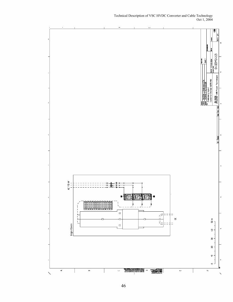
The outdoor AC yard including the power transformers, with a typical size of 55x38 meters, is also possible to separate from the converter building. The station as such is compact, needs little space, and can easily blend into the local surroundings. Much of the equipment is installed in enclosures at the factory, which minimizes construction and testing time at site. Preliminary layouts for the different substations and alternatives are found in section 9. These layouts have not yet been adapted to the proposed sites; the number and size of converters should be selected first, based on the feasibility study results in Volume 1. During the construction phase the area around the building and outdoor substation needs to be accessible. Examples of existing HVDC Light converter stations are shown in Figure 23 and Figure 24.
Figure 23 Three 60-MW Directlink converters working in parallel
Figure 24 The 330 MW Cross Sound Cable converter station at Shoreham, L.I.
32
Technical Description of VSC HVDC Converter and Cable Technology Oct 1, 2004
5 System Issues
5.1 Reactive Power Compensation The HVDC Light alternatives suggested require no reactive power compensation. In fact, the inherent reactive power capabilities [Section 1.3] of the voltage source converters themselves, up to their full MVA rating, can be used to regulate and support the AC system voltage independently at the terminal locations much like a virtual generator. There is no need for shunt reactors to absorb excess charging current from the cables as there is with AC cables. There is no need for shunt capacitor banks to support converter reactive power demand as with conventional converters. There is no need to provide stepped increases in reactive power supply to support increased loads on the DC system when power is increased following contingencies. The surplus reactive power capability of the converters can even be used to support the sudden increased reactive power demand due to incremental loading of AC transmission in response to contingencies. During light loading conditions, the HVDC Light converters can be used to mitigate overvoltages, which tend to occur under such conditions especially in systems with significant cable installations.
5.2 Resonance and Transient Overvoltages Power systems with large concentrations of shunt capacitance, e.g., from power factor correction capacitor banks or from high voltage AC cables, are subject to parallel resonances between the inductive reactance of the network and the connected capacitive reactance at any given network location. The weaker the network and the more the shunt capacitance, the lower the resonance frequency. A parallel resonance creates a high impedance. Resonances can be found everywhere in power systems. Lower resonance frequencies are of concern because they present a high impedance to the flow of harmonic currents, which can exist in AC networks. A common source of harmonic currents is transformers under high voltage conditions, during energization or following fault clearing. Other sources include non-linear loads, motor drives or power electronic devices. A high impedance to the flow of harmonic current can result in overvoltages similar to how a restriction in a pipeline can result in local overpressure when subjected to a surge or increase in flow. Since resonances impact overvoltages, they must be taken into account for insulation coordination especially in EHV networks far from load where damping is low. Conventional HVDC schemes with their concentration of shunt capacitance for filters and reactive power compensation can lower the resonance frequency. HVDC Light converters require reduced filtering to meet power quality standards and no reactive power compensation; therefore, their impact on the parallel resonance frequency at point of connection is less. Furthermore, the harmonic impedance of a voltage source converter is lower which further diminishes the impact. This subject is treated in detail
33
Technical Description of VSC HVDC Converter and Cable Technology Oct 1, 2004
in a separate report prepared by ABB Electric System Consulting entitled “Middletown – Norwalk Transmission Project, VSC HVDC System Feasibility Study”.
5.3 AC System Voltage Support
5.3.1 Steady State The continuous reactive power capability of the converter, up to its MVA limit, can be used for steady state AC voltage control. The following figure illustrates this capability for an HVDC Light voltage source converter operating at a given power level and AC voltage level. The circle represents the MVA capability of the converter operating as a rectifier, the vertical axis is for real power, P, and the horizontal axis is for reactive power, Q. The horizontal line represents a desired power dispatch of about 85% of rated capability. When operating at this power level, the converter can provide reactive power to the AC network anywhere from about 30% of its rating inductive to about 40% of its rating capacitive, i.e., anywhere inside the capability circle along the horizontal constant power line. The steady-state capability of the converter can be used to control the reactive power directly for a fixed contribution to the AC network or can be put under the control of a voltage regulator to assist other network voltage control devices to hold the network voltage at the desired level.
5.3.2 Dynamic The reactive power capability of the voltage source converters can be used as a dynamic reactive power reserve to provide contingency voltage support to the AC network similar to a static var compensator (SVC) or STATCOM. The same control techniques can be employed for dynamic voltage regulation to ensure the reactive power reserve margin is maintained and that voltage control is efficiently shared with other devices. Well-established control techniques can be used to optimize dynamic voltage control. These include integration of a slope to the
34
Technical Description of VSC HVDC Converter and Cable Technology Oct 1, 2004
voltage control characteristic, use of a small dead-band with selectable high and low limits about the desired operating point and inclusion of a slow susceptance or Q control to gradually restore the reserve margin after a contingency allowing slower devices to act.
5.3.3 Parallel Operation Parallel operation of HVDC converters is a well-established practice being used on the Pacific HVDC Intertie, New Zealand and other conventional schemes over the years. The Direct Link installation in Australia utilizes three parallel HVDC Light links. For Direct Link each parallel circuit is operated independently from a power control perspective. They do, however, act together to regulate the reactive power exchange and AC voltage at the sending and receiving terminals. Voltage control with parallel devices is common. Common examples are for parallel generators connected to the same bus or for parallel transformers with load tap changers in a substation. Techniques are available to evenly share in the regulating duty and avoid circulating reactive power.
5.3.4 Harmonics and Power Quality Applicable power quality standards, e.g., IEEE 519, can be met by filtering at each converter station. The following figure illustrates typical harmonic spectra for AC voltage and AC current measured at the Shoreham converter station operating as an inverter at 330 MW.
5.4 Integration of New Substations It is common practice to continue to serve intermediate loads from the lower voltage underlying transmission when overlaid by an EHV transmission for increased bulk power transmission capacity. This is possible since the new transmission serves to offload a portion of the end-to-end power transfer freeing up capacity on the lower voltage circuits. This practice also takes into account network reliability and protective simplicity. If, however, intermediate loads grow to the level where they can no longer be supported by the underlying transmission a new substation may be needed along the EHV line to reinforce the lower voltage transmission. The cost of doing so with an AC
35
Technical Description of VSC HVDC Converter and Cable Technology Oct 1, 2004
line are lower than for a DC line because of the need to install not only transformers, breakers, disconnect switches and protection but also to install another converter station. There are several options to address the addition of new load along the Middletown – Norwalk corridor. With the full HVDC Options (1 and 2), it is anticipated that the existing 115 kV lines will be offloaded somewhat by the scheduled power transfer over the DC links. The released capacity on the lower voltage lines can be used to serve new loads in the region. Alternatively, new higher current conductors or 115 kV cables can be added to serve the loads. As with new substations on EHV overlays, new HVDC converter stations could be constructed at selected locations only if and when needed. The surplus reactive power from a 115 kV underground cable is substantially lower than that from the 345 kV AC cables presently under consideration by NU. With the East Devon-Norwalk AC cable option (3), new substations can be built along the AC cable to serve the new loads. In option 3, 115 kV cables and/or new HVDC converter stations can serve new loads along the portion of the corridor between East Devon and Beseck. The 115 kV lines paralleling this segment can be off loaded to a larger extent than with the AC alternative since the DC power flow is controllable.
5.5 Integration of New Generation An additional degree of freedom exists in delivering generator power when an HVDC circuit is part of the generator outlet transmission. This flexibility is due to the controllability of the DC links. A similar situation exists when phase angle regulators influence the distribution of generator power on outlet transmission circuits. With this flexibility, however, comes the additional requirement to dispatch the power as desired on the controllable transmission circuit taking into account efficiency and network security. This action can be coordinated manually by the system operator, locally by simple automatic control functions such as the Tie Line Control described under Section 1.4 or remotely as part of the security constrained economic dispatch or security constrained unit commitment. Generators at different locations, such as Pequonnock or East Devon, can be scheduled independently respecting the security limitations of the transmission network. Radial connection of new generation to the DC link is not suggested for any of the DC alternatives. If new generation were added to the AC network in the vicinity of any of the intermediate converter stations, e.g., East Devon or Singer, it would need to be connected to the 115 kV bus via a new AC line. It would then have access to the HVDC transmission via the converter stations at those locations. The same considerations apply to tapping EHV lines for new generation as does for new substations, i.e., network security and protective aspects must be taken into account. If the converter capacity at the intermediate stations is insufficient to accommodate the new generation or the generation is not located in their general vicinity then new converters would have to be installed.
5.6 Short Circuit Current Limitation Fault current contribution from an AC circuit is only limited by the circuit impedance and can reach levels many times higher than its rated load current. This contribution
36
Technical Description of VSC HVDC Converter and Cable Technology Oct 1, 2004
adds significantly to the circuit breaker interrupting duty. Fault current contribution from an HVDC circuit however is limited. Normally the contribution from the converter itself is limited to the converter rating. With HVDC Light, if the AC voltage control response is filtered or inhibited during a fault, the contribution from the converter itself is further limited to the scheduled load current. HVDC Light converters are coupled to the AC network through a wye-delta transformer. If the transformer is connected with the wye winding grounded and connected on the network side, the transformer is a source of ground current during faults. Often this is desirable from a protection perspective. If, however, the local circuit breakers are close to their interrupting rating, the transformer can be connected ungrounded at the expense of some extra insulation.
5.7 Subsynchronous Torsional Interaction Mitigation When an AC generator is closely coupled to a constant power device such as a DC terminal, a control interaction can occur which destabilizes the lightly damped mechanical torsional modes of the turbine-generator shaft. This potential for torsional interaction must be addressed in the control design. A reference white paper describing this matter, the conditions under which it can occur, the design techniques for avoiding or mitigating the interaction and the related experience from actual projects is available.
6 System Operation
6.1 Steady-State Operation Since HVDC transmission is controllable, it must be told to start, stop and ramp to the desired power level to meet system daily and hourly requirements. Since load patterns are predictable and generation dispatched economically while respecting system security, transfer requirements are also predictable. HVDC Light has no minimum power level so it can be scheduled anywhere within its capability. HVDC transmission dispatching can be manual or handled automatically if there is a desire or need to do so.
6.2 Post-Contingency
6.2.1 Manual If transmission or generator outages occur, the DC power levels will remain as scheduled, unless it is ordered to go to a new post-contingency level. The suggested alternatives are designed such that no immediate rescheduling is required following a contingency. This should be verified in the contingency analysis. If, however, it is desired to bring the network to a new state in order to better pre-position it for a subsequent event, then this can be done manually. The most obvious example would be to increase the power on the DC transmission following loss of a parallel AC or DC transmission circuit.
6.2.2 Stand-alone A stand-alone local control could be used to automatically respond to loss of a parallel DC circuit or converter. This control could be similar to that described in Section 1.4 under “Pole Loss Compensation” or “Converter Loss Compensation.” Use of these controls is straightforward and well established.
37
Technical Description of VSC HVDC Converter and Cable Technology Oct 1, 2004
6.2.3 Dispatch More sophisticated post-contingency controls can be devised and implemented at a higher level if desired. An example of such a scheme could be the order to increase HVDC power transfer from Beseck to Norwalk in response to loss of the Plumtree to Long Mountain segment. Please see the figure below. With the HVDC alternatives, however, such schemes are not suggested or deemed necessary. Chances are that if a circuit overloads for one contingency, it may overload for others as well. In such a case, the circuit can be reinforced or the flow restricted locally instead. A common example is when one of two parallel AC cables trips during heavy transfer conditions, the remaining cable may overload. In such a case, a phase angle regulator or switched reactor in series with the cable can be used to suppress the locally detected overload.
Norwalk Beseck
Singer Devon
Hadom Nk
Long Mtn
PlumtreeMerid Scovl Rk
E Shore
Frstbdge Southgtn
Underlying Parallel Transmission
Norwalk Beseck
Singer Devon
Hadom Nk
Long Mtn
PlumtreeMerid Scovl Rk
E Shore
Frstbdge Southgtn
Underlying Parallel Transmission Figure 26
6.3 Security Constrained Economic Dispatch and Unit Commitment For optimum system performance and ease of operation, any of the HVDC Light configurations suggested in Section 1.5 can be incorporated into the security constrained economic dispatch of the NE ISO. In doing so, the scheduled and real time flows on the HVDC links can be determined taking into account security constraints on the other network elements, e.g., the parallel 345 kV and underlying 115 kV transmission. Scheduling transmission flows on the DC links would then be similar to the security constrained scheduling of generation as currently done by the NE ISO. ABB or another EMS supplier can easily incorporate dispatch of the HVDC system into the NE ISO’s Energy Management System. ABB has done so for HVDC links and phase angle regulators for EMS supplied for other system operators.
6.4 Reliability, Availability and Maintenance HVDC Converter Stations contain more equipment than do AC Substations. Therefore, the converter outage rates and maintenance requirements are higher. Redundancy is used
38
Technical Description of VSC HVDC Converter and Cable Technology Oct 1, 2004
to keep down the outage rates. On the other hand, the outage rates and maintenance requirements for the underground cables are lower due to there being fewer cables with simpler design. For a two-terminal HVDC Light transmission system, including the cables and converter stations at each end, availability for existing projects has been guaranteed at 98%. This covers both scheduled and forced unavailability. This level has been met for the Cross Sound Cable Project. For multi-terminal systems, the station unavailability has to be considered on a per station basis, since loss of one converter does not impact the transmission availability between the remaining stations on the same circuit.
7 Price Estimates The estimated budgetary prices for the HVDC Light transmission systems defined in section 1.5 are found in the table below. All price estimates are in MUSD, and are for a turnkey engineer/procure/construct (EPC) delivery of converter stations and cables. Please note that the cables for option 3 are only for the Beseck-East Devon segment, all other cables are for the complete run from Beseck to Norwalk Substation.
Note: The installation price range is based on 100% cable duct installation. This price can be lower if direct burial of the cables is selected as method.
Under the concept of Converter station, the following works are included • system studies • electrical and civil design • supply of equipment to work site • civil works • installation of electrical and mechanical equipment • commissioning • training of operators and maintenance personnel • spare parts • documentation
Under the concept of Cable, the following is included
• design • type tests • supply of cable to work site
39
Technical Description of VSC HVDC Converter and Cable Technology Oct 1, 2004
• cable joints • termination equipment • supervision of laying, jointing and termination
The cable installation includes
• installation of cable ducts according to section 3.3 • pulling of cables • jointing • termination • voltage withstand test after installation
8 References and Common Experience
8.1 Cable Experience and References
8.1.1 HVDC Light references The reference list of the installed HVDC Light cable systems is as follows:
Project Customer Country Year Type of Quantity Voltage Conductor
installation (m) (kV) (mm2) Material Troll A Statoil Norway 2004 Submarine 284 000 60 300 Cu Troll A Statoil Norway 2004 In station 510 60 630 Cu Cross Sound TransÉnergie US United States 2002 Submarine 83 240 150 1300 Cu Murraylink TransÉnergie US Australia 2002 Underground 223 200 150 1200 Al Murraylink TransÉnergie US Australia 2002 Underground 136 800 150 1400 Al GotLight GEAB Sweden 2002 In station 410 150 630 Cu Murraylink TransÉnergie US Australia 2002 In station 1 450 150 630 Cu Cross Sound TransÉnergie US United States 2002 In station 1 500 150 630 Cu Tjaereborg ELTRA Denmark 1999 Underground 9 000 10 240 Al DirectLink TransÉnergie US Australia 1999 Underground 390 000 84 630 Al GotLight Gotland Energy Sweden 1998 Underground 140 000 80 340 Al Total: 1 354 110m delivered HVDC Light cable
8.1.2 Installation in ducts
8.1.2.1 HVDC Light cables in duct installations Most of the installed HVDC Light cables are submarine cables or direct buried land cables. Limited lengths in many projects are however installed in ducts, e.g. in a 1950 ft directional drilling at the landfall in New Haven for the Cross Sound cable, and at the shore end in Norway for the Troll A cables.
40
Technical Description of VSC HVDC Converter and Cable Technology Oct 1, 2004
For Murraylink there are a number of shorter distances were the cables are installed in ducts, at e.g. railway an road crossings, according to following tables:
River Crossing Bore No Location / Obstruction Length (m) Casing
1 Murray River 330 250 HDPE South Australian Duct Lengths Bore No Location / Obstruction Length (m) Casing
1 Cultural Site (Middens) Lyrup Forest 38 2x200 HDPE 2 Lagoon in Lyrup Forest 62 2x225 HDPE 3 Under gas main and Brown St 68 2x200 HDPE 4 Brown St under tree and HV Cable 43 2x200 HDPE 5 Gurra Rd and Brown St Intersection 30 2x200 HDPE 6 Brown St and Old Lyrup Rd Lagoon 60 2x225 HDPE 7 Loxton Rd and Old Lyrup Rd intersection 14 2x200 HDPE 8 Crosses Loxton Rd 16 2x200 HDPE 9 Pike Creek Rd and Loxton Rd intersection 13 2x200 HDPE 10 Crosses Loxton Rd 18 2x200 HDPE 11 Crosses Loxton Rd 19 2x200 HDPE 12 Sturt Highway and Loxton Rd intersection 28 2x225 HDPE 13 Crosses Sturt Hwy at Yamba Roadhouse 40 2x225 HDPE 14 Crosses Sturt Hwy at Yamba Roadhouse 43 2x225 HDPE 15 Crosses Sturt Hwy 28 2x200 HDPE 16 Crosses Sturt Hwy 30 2x200 HDPE 17 Crosses Morgan Rd 18 2x200 HDPE 18 Crosses Morgan Rd 18 2x200 HDPE 19 Morgan Rd and Sturt Hwy intersection 24 2x200 HDPE 20 Crosses Sturt Highway 24 2x200 HDPE 21 Crosses Sturt Highway 24 2x200 HDPE 22 Crosses Sturt Highway 24 2x200 HDPE 23 Crosses Sturt Highway into old rubbish tip 24 2x200 HDPE 24 Sturt Hwy and Settlement Rd intersection 24 2x200 HDPE
OPEN CUT DUCT CROSSINGS 4 Brown St under tree and HV Cable 43 2x200 HDPE
41
Technical Description of VSC HVDC Converter and Cable Technology Oct 1, 2004
Victorian Duct Crossings
Bore No Location Obstruction Length (m) Casing 1 Woomera Av (Start job) Water Channels x 2 26 2x225 HDPE2 Woomera Av (Pump St.) Rural bitumen road 12 2x225 HDPE3 Pumps Rd / Woomera Av Rural bitumen road 18 2x225 HDPE4 Woomera Av / Cassia St Rural bitumen road 12 2x225 HDPE5 Woomera Av / Cotterills Hill Rd Rural bitumen road 12 2x225 HDPE6 Stewart Rd / Woomera Av Rural bitumen road 35 2x225 HDPE7 Kulkyne Way (Hakea St) Rural bitumen road 24 2x225 HDPE8 Lignum Av / Hakea St Rural bitumen road 14 2x225 HDPE9 Calder Hwy / Railway Wat Ch / Hwy / Rwy 107 2x200 Steel
OPEN CUT DUCT CROSSINGS "A" Dirt road off Woomera Av Rural gravel road 15 2x225 HDPE"B" Tulloch Rd / Wilga Rd Rural bitumen road 18 2x225 HDPE14 Magnum Av Railway Reserve 20 2x225 HDPE
8.1.2.2 XLPE cables in duct installations Since the thermal and mechanical properties (which are the properties critical for different installation conditions) of HVDC Light cables and XLPE insulated cables are identical, also XLPE cables in duct bank installations are relevant as references. Customer Country Year Quantity4 Voltage Conductor Remark
(m) (kV) (mm2) Material Con Edison USA 2003 229 145 2000kcmil Cu Con Edison USA 2003 1 341 145 1500 kcmil Cu Florida Power and Light Co USA 2003 500 145 1 200 Cu Austin Energy USA 2003 720 145 2000 Cu Hochiminh City Power Company Vietnam 2002 38 600 245 1 600 Cu Ducts 15 000 m Consolidated Edison USA 2001 18 400 145 750 Cu China Light & Power China 2000 20 720 145 1 000 Cu Ducts 1000 +
1400 m Florida Power and Light Co USA 1993 9500 138 1259 Cu Fondo Aeronautico Nacional Colombia 1981 4 000 123 400 Cu
4 This column shows total cable length in the project. If only a part of the length is installed in ducts, it is shown in the remark column
42
Technical Description of VSC HVDC Converter and Cable Technology Oct 1, 2004
Project Rating Distance. Ordered Application Hellsjön 3 MW 10 km April 1994 Converting AC to DC AC network
connection Gotland 50 MW 70 km Dec 1997 Wind power,
Underground cable Embedded in AC network
Tjæreborg 7 MW 4 km June 1998 Wind power, Underground cable
Embedded in AC network
Directlink 180 MW 65 km Dec 1998 Interconnection Underground cable
Three parallel 60 MW links
Eagle Pass 36 MW BtB July 1999 Asynchronous tie Cross Sound Cable
330 MW 40 km Aug 2000 Interconnection under water
Embedded in AC network
Murraylink 200 MW 180 km Dec 2000 Interconnection, underground cable
Troll 2 x 40 MW
70 km May 2002 Offshore platform feeding
9 Drawings The following four drawings show preliminary converter station layouts for the different sizes of converters and the different configuration options.
43
Technical Description of VSC HVDC Converter and Cable Technology Oct 1, 2004
44
Technical Description of VSC HVDC Converter and Cable Technology Oct 1, 2004
45
Technical Description of VSC HVDC Converter and Cable Technology Oct 1, 2004
46
Technical Description of VSC HVDC Converter and Cable Technology Oct 1, 2004