Large Synoptic Survey Telescope (LSST) Data Management Middleware UML Use Case and Activity Model Kian-Tat Lim, Robyn Allsman, Jeff Kantor LDM-146 Latest Revision: October 10, 2013 This LSST document has been approved as a Content-Controlled Document by the LSST DM Technical Control Team. If this document is changed or superseded, the new document will retain the Handle designation shown above. The control is on the most recent digital document with this
Transcript
Large Synoptic Survey Telescope (LSST)
Data Management Middleware UML Use Case and Activity Model
Kian-Tat Lim, Robyn Allsman, Jeff Kantor
LDM-146
Latest Revision: October 10, 2013
This LSST document has been approved as a Content-Controlled Document by the LSST DM Technical
Control Team. If this document is changed or superseded, the new document will retain the Handle
designation shown above. The control is on the most recent digital document with this Handle in the
LSST digital archive and not printed versions. Additional information may be found in the LSST DM TCT
minutes.
Data management Middleware UML Use Case and Activity Model LDM-146 10/10/2013
Change Record
Version Date Description Owner name
1 1/28/2011 Update Document to reflect Model based on Data Challenge 3
J. Kantor
2 7/12/2011 Update Document to reflect Model based on Data Challenge 3B PT1 R. Allsman
3 8/18/2011 General updates R. Allsman
4 9/13/2013 Final Design updates (MW revision 1.59) R. Allsman
5 10/10/2013 Formatting revisions (Revision 1.62); TCT Approved R. Allsman
The contents of this document are subject to configuration control by the LSST DM Technical Control Team
i
Data management Middleware UML Use Case and Activity Model LDM-146 10/10/2013
Table of Contents
Change Record.............................................................................................................................................. i
The contents of this document are subject to configuration control by the LSST DM Technical Control Team
ii
Data management Middleware UML Use Case and Activity Model LDM-146 10/10/2013
Data Management Middleware UML Use Case and Activity Model
1 Middleware Activities
1.1 Actors and Agents
Actor WBS Description
Database Administrator 02C.06.02
The Database Administrator is any user that has the access necessary to invoke database administration operations (e.g. configure Database security, system parameters, partitioning, resource utilization, etc.) related to in the LSST DM Database management.
Production Coordinator 02C.01.02 The Production Coordinator is any user that has the access necessary to oversee and certify the production and release of LSST Data Products.
Science User 02C.05 This Science User is any user who has access to LSST Data Products, Pipelines, or both.
System Administrator 02C.07.02
The System Administrator is any user that has the access necessary to invoke system administration operations (e.g. configure security, equipment, system parameters, etc.) in the LSST Data Management Control System.
Checkpoint/Restart Services 02C.06.03.04
Checkpoint/Restart Services agent provides the orderly halt of pipeline processing including the collection of all data required for its later resumption at the same point at which it was first checkpointed.
Data Access Client Framework 02C.06.02.01
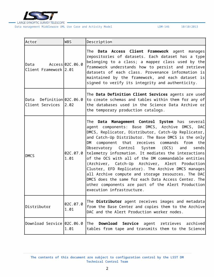
The Data Access Client Framework agent manages repositories of datasets. Each dataset has a type belonging to a class; a mapper class used by the framework understands how to persist and retrieve datasets of each class. Provenance information is maintained by the framework, and each dataset is signed to verify its integrity and authenticity.
Data Definition Client 02C.06.02.02 The Data Definition Client Services agents are used to create schemas and
The contents of this document are subject to configuration control by the LSST DM Technical Control Team
1
Data management Middleware UML Use Case and Activity Model LDM-146 10/10/2013
Actor WBS Description
Services tables within them for any of the databases used in the Science Data Archive or the temporary production catalogs.
DMCS 02C.07.01.01
The Data Management Control System has several agent components: Base DMCS, Archive DMCS, DAC DMCS, Replicator, Distributor, Catch-Up Replicator, and Catch-Up Distributor. The Base DMCS is the only DM component that receives commands from the Observatory Control System (OCS) and sends telemetry information. It mediates the interactions of the OCS with all of the DM commandable entities (Archiver, Catch-Up Archiver, Alert Production Cluster, EFD Replicator). The Archive DMCS manages all Archive compute and storage resources. The DAC DMCS does the same for each Data Access Center. The other components are part of the Alert Production execution infrastructure.
Distributor02C.07.01.01 The Distributor agent receives images and metadata from the Base Center
and copies them to the Archive DAC and the Alert Production worker nodes.
Download Service 02C.06.01.01 The Download Service agent retrieves archived tables from tape and transmits them to the Science User.
Event Broker02C.07.02.01 The Event Broker agent mediates the reliable, high-capacity
publish/subscribe mechanism used to communication between DM components.
Event Monitor 02C.07.02.01
The Event Monitor agent connected to the Event Broker performs accumulation of event statistics and recognition of patterns of events, allowing triggering of actions (including publishing of new events). Event Monitors will typically be installed by the Orchestration Manager or the Data Management Control System.
Event Services02C.07.02.01 Event Services agents allow DM components, including the DMCS and
individual tasks, to communicate with each other using a reliable, high-capacity publish/subscribe mechanism mediated by an Event Broker.
Image and File Archive 02C.06.01.02 The Image and File Archive agent provides a Web-based and command-line client interface to the file-based portion of the Science Data Archive.
The contents of this document are subject to configuration control by the LSST DM Technical Control Team
2
Data management Middleware UML Use Case and Activity Model LDM-146 10/10/2013
Actor WBS Description
Image and File Services 02C.06.02.04
The Image and File Services agent perform image processing in order to regenerate virtual image data products and to generate images of spatial regions of interest (both large mosaics and small postage stamps). In addition, Image and File Services manages caches of files and images to speed up retrieval.
Ingest Service 02C.06.01.01 The Ingest Services agent provides database ingest support for all Catalogs in the Science Data Archive.
Inter-Process Messaging Services 02C.06.03.03
The Inter-Process Messaging Services agents enable tasks to send and receive data items according to a defined communications geometry (e.g. broadcast/scatter from each task to all others, gather from all tasks to a designated one, exchange data with neighbors in a grid). A variety of communications mechanisms (e.g. MPI or the LSST DM Event Services) are supported with the same interface.
Logging Services 02C.06.03.02
The Logging Services agent enable tasks to produce log entries, including fatal errors, warnings, and debugging messages. Log entries may be sent to a variety of destinations including standard streams, files, and the Event Services broker. Each entry may have metadata associated with it. An external configuration specifies which entries go to which destinations with which message format.
Orchestration Manager 02C.07.01.02
The Orchestration Manager agent deploys tasks to compute platforms, setting up the execution environment for them and ensuring that input datasets and storage resources are available. It can schedule the tasks for execution according to data dependencies, resource availability, and other factors. It tracks the status of all tasks and can terminate tasks early if necessary.
Pipeline Construction Toolkit 02C.06.03.01
The Pipeline Construction Toolkit agent enables application developers to create tasks to perform operations and execute algorithms within the LSST DM stack framework. Tasks may be nested hierarchically. Each task has a configuration that controls its execution.
Query Services 02C.06.02.03 The Query Services agent performs scalable execution of SQL-dialect queries on vast amounts of data partitioned in chunks across a platform
The contents of this document are subject to configuration control by the LSST DM Technical Control Team
3
Data management Middleware UML Use Case and Activity Model LDM-146 10/10/2013
Actor WBS Description
consisting of a cluster of machines.
Release Service02C.06.01.01 After a Data Release Production is complete, the Release Service agent
makes the new catalog available for access at the same time that an older catalog is removed.
Replicator 02C.07.01.01 The Replicator agent aggregates data and forwards the aggregate dataset to a connected Distributor.
1.2 Science Data Archive
1.2.1 Catalogs, Alerts, and Metadata
WBS: 02C.06.01.01
The Catalogs, Alerts, and Metadata component includes logical and physical schema designs for all catalogs in the Science Data Archive, including a database of issued alerts, a database of image metadata, and a replica of the Engineering and Facilities Database. In addition to these layouts, there are services provided by this component: an Ingest Service, a Release Service, and a Download Service.
1.2.1.1 Ingest Image Metadata
WBS: 02C.06.01.01
Copy metadata about an Image Dataset into appropriate Tables in a Catalog.
INPUT: Destination Catalog, Image Dataset
Scenario Steps Summary Rejoins at
Basic Path 1. Ingest Service invokes Data Access Client Framework:Retrieve Dataset to retrieve metadata from Image Dataset.
2. Ingest Service translates metadata into relations.3. Ingest Service stores relations in table(s) in catalog.4. Ingest Service invokes Data Access Client
Framework:Retrieve Dataset Provenance to retrieve
The contents of this document are subject to configuration control by the LSST DM Technical Control Team
4
Data management Middleware UML Use Case and Activity Model LDM-146 10/10/2013
Scenario Steps Summary Rejoins at
provenance of Image Dataset.5. Ingest Service translates Provenance into Relations.6. Ingest Service stores Provenance Relations in Table(s) in
Catalog.
1.2.1.2 Ingest FITS Table
WBS: 02C.06.01.01
Copy information from a FITS table into appropriate tables in a Catalog.
INPUT: Destination catalog FITS table dataset
Scenario Steps Summary Rejoins at
Basic Path
1. Ingest Service invokes Data Access Client Framework:Retrieve Dataset to Retrieve FITS Table.
2. Ingest Service extracts schema from FITS Table.3. Ingest Service translates FITS Schema into Relational
Schema.4. Ingest Service invokes Data Definition Client Services:Create
Table to create Tables in Catalog.5. Ingest Service stores FITS Table data in Tables in Catalog.6. Ingest Service invokes Data Access Client
Framework:Retrieve Dataset Provenance to retrieve Provenance of FITS Table.
7. Ingest Service translates Provenance into relations.8. Ingest Service stores Provenance in Table(s) in Catalog.
1.2.1.3 Bulk Download Catalog
WBS: 02C.06.01.01
Portions or all of a Catalog, including older Catalogs no longer on disk, may be downloaded as bulk files (not as a Database query).
INPUT: Data Release Production number, Catalog tables: all or subset
The contents of this document are subject to configuration control by the LSST DM Technical Control Team
5
Data management Middleware UML Use Case and Activity Model LDM-146 10/10/2013
Scenario Steps Summary Rejoins at
Basic Path
1. Download Service retrieves archived tables from tape.
2. Download Service transmits archived tables to Science User.
1.2.1.4 Ingest Multiple FITS Tables
WBS: 02C.06.01.01
Copy information from many FITS tables into appropriate Tables in a Catalog, repartitioning the data if necessary.
INPUT: Destination Catalog, FITS Table Datasets
Scenario Steps Summary Rejoins at
Basic Path
1. If Dataset type is a Distributed Table(see AltPath: Dataset Type not Distributed Table)
2. Ingest Service invokes Query Services: Partition Data and Load Distributed Table.
3. For each FITS Table:4. .....Ingest Service invokes Data Access Client Framework:
Retrieve Dataset Provenance to retrieve Provenance of FITS table .
5. .....Ingest Service translates Provenance into relations.6. .....Ingest Service stores Provenance in Tables in Catalog.7. done:8. fin:
AltPath: Dataset Type not Distributed Table
1. For each FITS table:2. .....Ingest Service invokes Ingest FITS Table.3. done:
Basic Path step:8
1.2.1.5 Release New Catalog
WBS: 02C.06.01.01
After a Data Release Production is complete, the new catalog is made available for access at the same time that an older catalog is removed.
INPUT: Data Release catalog; Previous Data Release catalog; Penultimate Data Release catalog
The contents of this document are subject to configuration control by the LSST DM Technical Control Team
6
Data management Middleware UML Use Case and Activity Model LDM-146 10/10/2013
Scenario Steps Summary Rejoins at
Basic Path
1. Release Service marks older Catalog as to-be-deleted in all DACs.
2. Release Service marks old Catalog as older in all DACs.
3. Release Service marks current Catalog as old in all DACs.
4. Release Service marks new Catalog as current in all DACs.
5. Release Service removes to-be- deleted Catalog(s) in all DACs.
1.2.1.6 Ingest Production Results
WBS: 02C.06.01.01
Copy information, from the results of executing a task in a Production, into a Catalog.
INPUT: Destination Catalog; Dataset Type, Repository, Selection Information
Scenario Steps Summary Rejoins at
Basic Path
1. If Dataset type is Images:(see AltPath: Dataset Type is FITS Tables)
2. For each Image:3. .....Ingest Service invokes Ingest Image Metadata.4. done:5. fin:
AltPath: Dataset Type is FITS Tables
1. For each FITS Table:2. Ingest Service invokes Ingest Multiple FITS Tables3. done:
Basic Path step:5
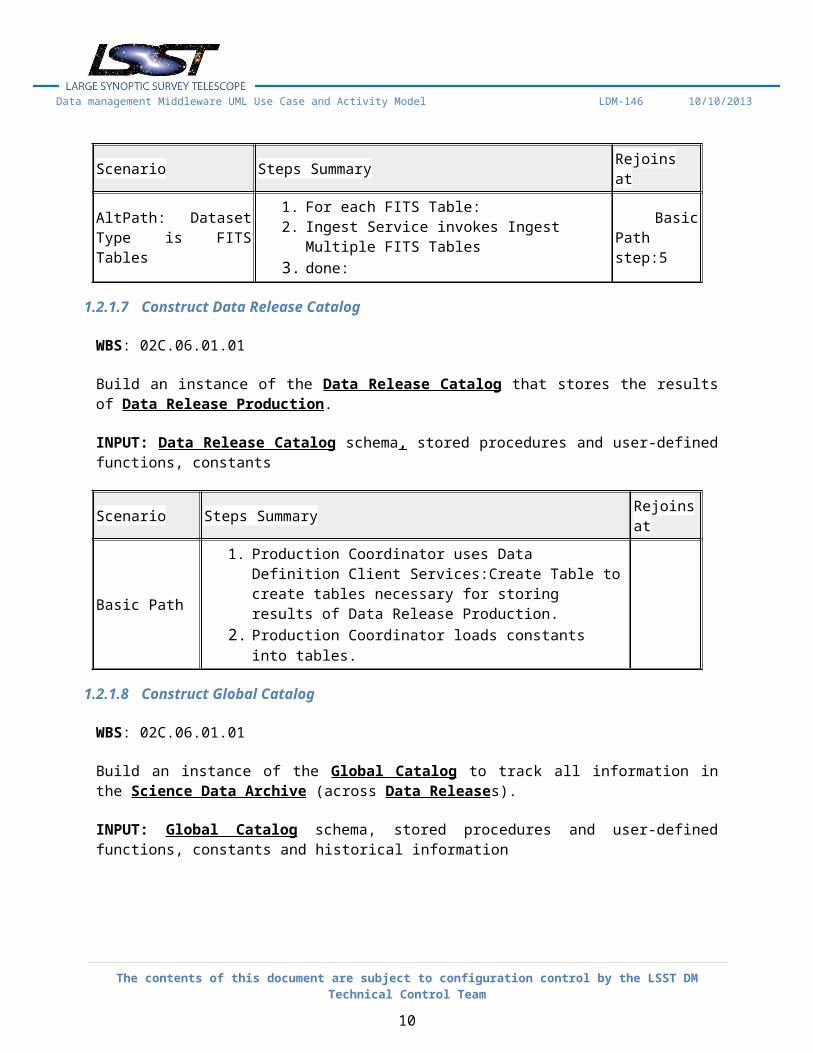
1.2.1.7 Construct Data Release Catalog
WBS: 02C.06.01.01
Build an instance of the Data Release Catalog that stores the results of Data Release Production.
INPUT: Data Release Catalog schema, stored procedures and user-defined functions, constants
The contents of this document are subject to configuration control by the LSST DM Technical Control Team
7
Data management Middleware UML Use Case and Activity Model LDM-146 10/10/2013
Scenario Steps Summary Rejoins at
Basic Path
1. Production Coordinator uses Data Definition Client Services:Create Table to create tables necessary for storing results of Data Release Production.
2. Production Coordinator loads constants into tables.
1.2.1.8 Construct Global Catalog
WBS: 02C.06.01.01
Build an instance of the Global Catalog to track all information in the Science Data Archive (across Data Releases).
INPUT: Global Catalog schema, stored procedures and user-defined functions, constants and historical information
Scenario Steps Summary Rejoins at
Basic Path
1. Database Administrator uses Data Definition Client Services:Create Table to create tables necessary for tracking versions and provenance of all other catalogs; users and privileges; and stored procedures and user-defined functions.
2. Database Administrator loads constants and historical information into tables.
1.2.1.9 Construct Temporary Data Release Production Catalog
WBS: 02C.06.01.01
Build an instance of a Catalog to be used for temporary, intermediate storage during the execution of the Data Release Production.
INPUT: Temporary Data Release Production Catalog schema, stored procedures and user-defined functions, constants and historical information
Scenario Steps Summary Rejoins at
Basic Path 1. Production Coordinator uses Data Definition Client Services:Create Table to create tables necessary for intermediate storage during Data Release Production.
The contents of this document are subject to configuration control by the LSST DM Technical Control Team
8
Data management Middleware UML Use Case and Activity Model LDM-146 10/10/2013
Scenario Steps Summary Rejoins at
2. Production Coordinator loads constants and historical information into tables.
1.2.1.10 Construct Temporary Alert Production Catalog
WBS: 02C.06.01.01
Build an instance of a Catalog to be used for temporary, intermediate storage during the execution of the Alert Production.
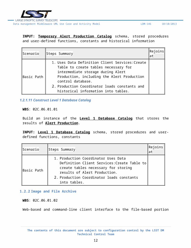
INPUT: Temporary Alert Production Catalog schema, stored procedures and user-defined functions, constants and historical information
Scenario Steps Summary Rejoins at
Basic Path
1. Uses Data Definition Client Services:Create Table to create tables necessary for intermediate storage during Alert Production, including the Alert Production control database.
2. Production Coordinator loads constants and historical information into tables.
1.2.1.11 Construct Level 1 Database Catalog
WBS: 02C.06.01.01
Build an instance of the Level 1 Database Catalog that stores the results of Alert Production.
1. Production Coordinator Uses Data Definition Client Services:Create Table to create tables necessary for storing results of Alert Production.
2. Production Coordinator loads constants into tables.
1.2.2 Image and File Archive
WBS: 02C.06.01.02
The contents of this document are subject to configuration control by the LSST DM Technical Control Team
9
Data management Middleware UML Use Case and Activity Model LDM-146 10/10/2013
Web-based and command-line client interface to the file-based portion of the Science Data Archive. Uses the Image and File Services and Data Access Client Framework.
1.2.2.1 Bulk Download Images and Files
WBS: 02C.06.01.02
Large numbers of images and/or files may be bulk downloaded rather than retrieved one by one.
INPUTS: Identifying information for image/file set
Scenario Steps Summary Rejoins at
Basic Path
1. For each image/file in set:2. .....Image and File Archive invokes Image and File
Services:Retrieve Released Image or File to retrieve image/file.
3. .....Image and File Archive transmits image/file to Science User.
4. done:
1.2.2.2 List Released Images and Files
WBS: 02C.06.01.02
Images and files matching search criteria may be listed.
INPUT: Specific release; Search expression, including desired Dataset Type, date ranges, spatial region, and other criteria
Scenario Steps Summary Rejoins at
Basic Path 1. Image and File Archive displays all images/files that match search expression
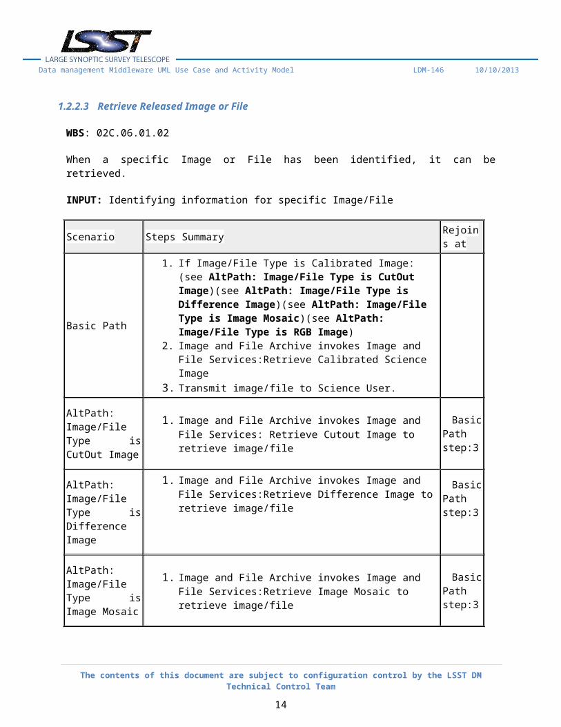
1.2.2.3 Retrieve Released Image or File
WBS: 02C.06.01.02
When a specific Image or File has been identified, it can be retrieved.
INPUT: Identifying information for specific Image/File
The contents of this document are subject to configuration control by the LSST DM Technical Control Team
10
Data management Middleware UML Use Case and Activity Model LDM-146 10/10/2013
Scenario Steps Summary Rejoins at
Basic Path
1. If Image/File Type is Calibrated Image:(see AltPath: Image/File Type is CutOut Image)(see AltPath: Image/File Type is Difference Image)(see AltPath: Image/File Type is Image Mosaic)(see AltPath: Image/File Type is RGB Image)
2. Image and File Archive invokes Image and File Services:Retrieve Calibrated Science Image
3. Transmit image/file to Science User.
AltPath: Image/File Type is CutOut Image
1. Image and File Archive invokes Image and File Services: Retrieve Cutout Image to retrieve image/file
Basic Path step:3
AltPath: Image/File Type is Difference Image
1. Image and File Archive invokes Image and File Services:Retrieve Difference Image to retrieve image/file
Basic Path step:3
AltPath: Image/File Type is Image Mosaic
1. Image and File Archive invokes Image and File Services:Retrieve Image Mosaic to retrieve image/file
Basic Path step:3
AltPath: Image/File Type is RGB Image
1. Image and File Archive invokes Image and File Services:Retrieve RGB Image to retrieve image/file
Basic Path step:3
1.3 Data Access Services
WBS: 02C.06.02
These services provide the ability to ingest, index, federate, query, and administer DMS data products on distributed, heterogeneous storage system and data server architectures. All services will be implemented to provide reasonable fault-tolerance and autonomous recovery in the event software and hardware failures.
1.3.1 Data Access Client Framework
WBS: 02C.06.02.01
The Data Access Client Framework manages repositories of datasets. Each dataset has a type belonging
The contents of this document are subject to configuration control by the LSST DM Technical Control Team
11
Data management Middleware UML Use Case and Activity Model LDM-146 10/10/2013
to a class; a mapper class used by the framework understands how to persist and retrieve datasets of each class. Provenance information is maintained by the framework, and each dataset is signed to verify its integrity and authenticity.
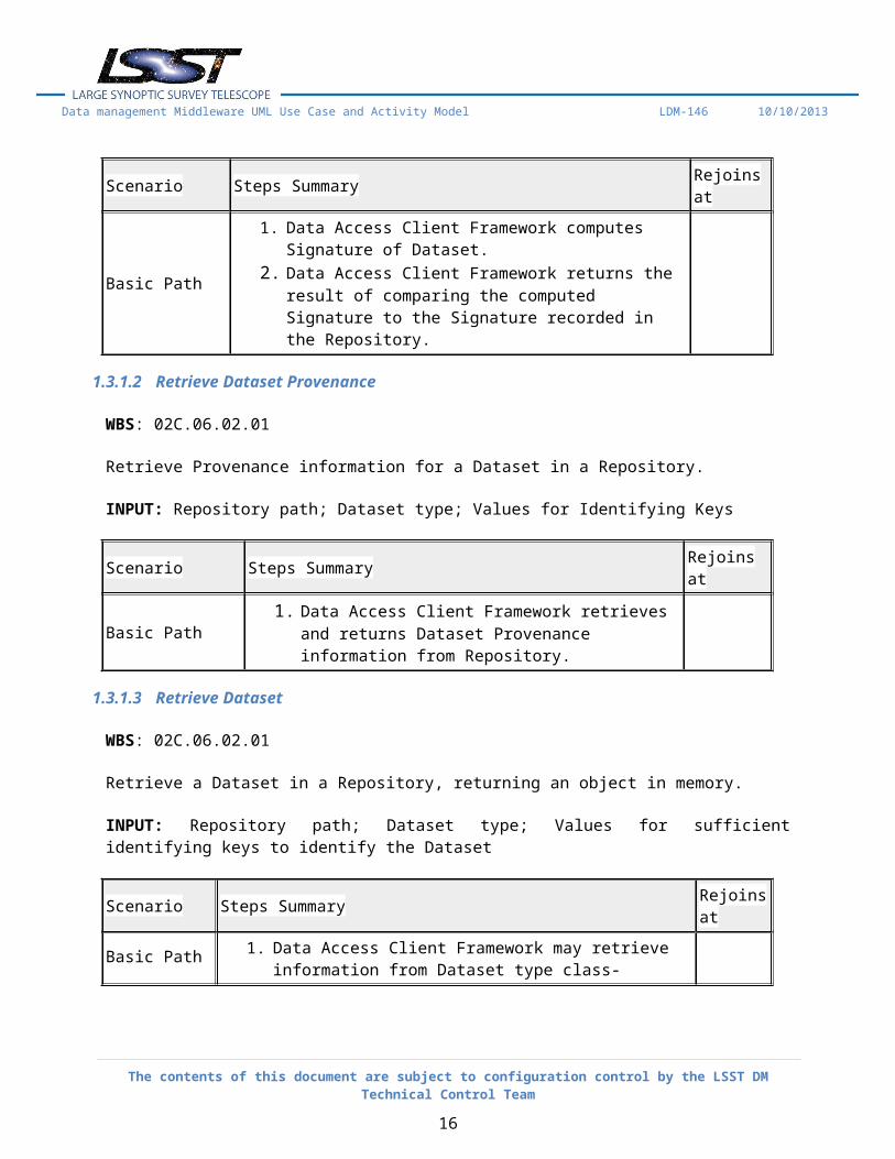
1.3.1.1 Verify Dataset Signature
WBS: 02C.06.02.01
Verify the integrity of a Dataset in a Repository.
INPUT: Repository path; Dataset type; Values for Identifying Keys
Scenario Steps Summary Rejoins at
Basic Path
1. Data Access Client Framework computes Signature of Dataset.
2. Data Access Client Framework returns the result of comparing the computed Signature to the Signature recorded in the Repository.
1.3.1.2 Retrieve Dataset Provenance
WBS: 02C.06.02.01
Retrieve Provenance information for a Dataset in a Repository.
INPUT: Repository path; Dataset type; Values for Identifying Keys
Scenario Steps Summary Rejoins at
Basic Path 1. Data Access Client Framework retrieves and returns Dataset Provenance information from Repository.
1.3.1.3 Retrieve Dataset
WBS: 02C.06.02.01
Retrieve a Dataset in a Repository, returning an object in memory.
INPUT: Repository path; Dataset type; Values for sufficient identifying keys to identify the Dataset
The contents of this document are subject to configuration control by the LSST DM Technical Control Team
12
Data management Middleware UML Use Case and Activity Model LDM-146 10/10/2013
Scenario Steps Summary Rejoins at
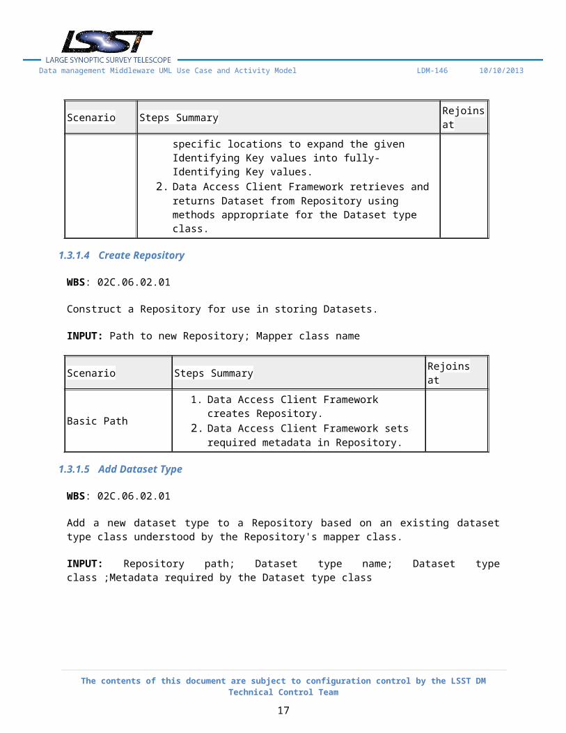
Basic Path
1. Data Access Client Framework may retrieve information from Dataset type class-specific locations to expand the given Identifying Key values into fully-Identifying Key values.
2. Data Access Client Framework retrieves and returns Dataset from Repository using methods appropriate for the Dataset type class.
1.3.1.4 Create Repository
WBS: 02C.06.02.01
Construct a Repository for use in storing Datasets.
INPUT: Path to new Repository; Mapper class name
Scenario Steps Summary Rejoins at
Basic Path1. Data Access Client Framework creates Repository.2. Data Access Client Framework sets required
metadata in Repository.
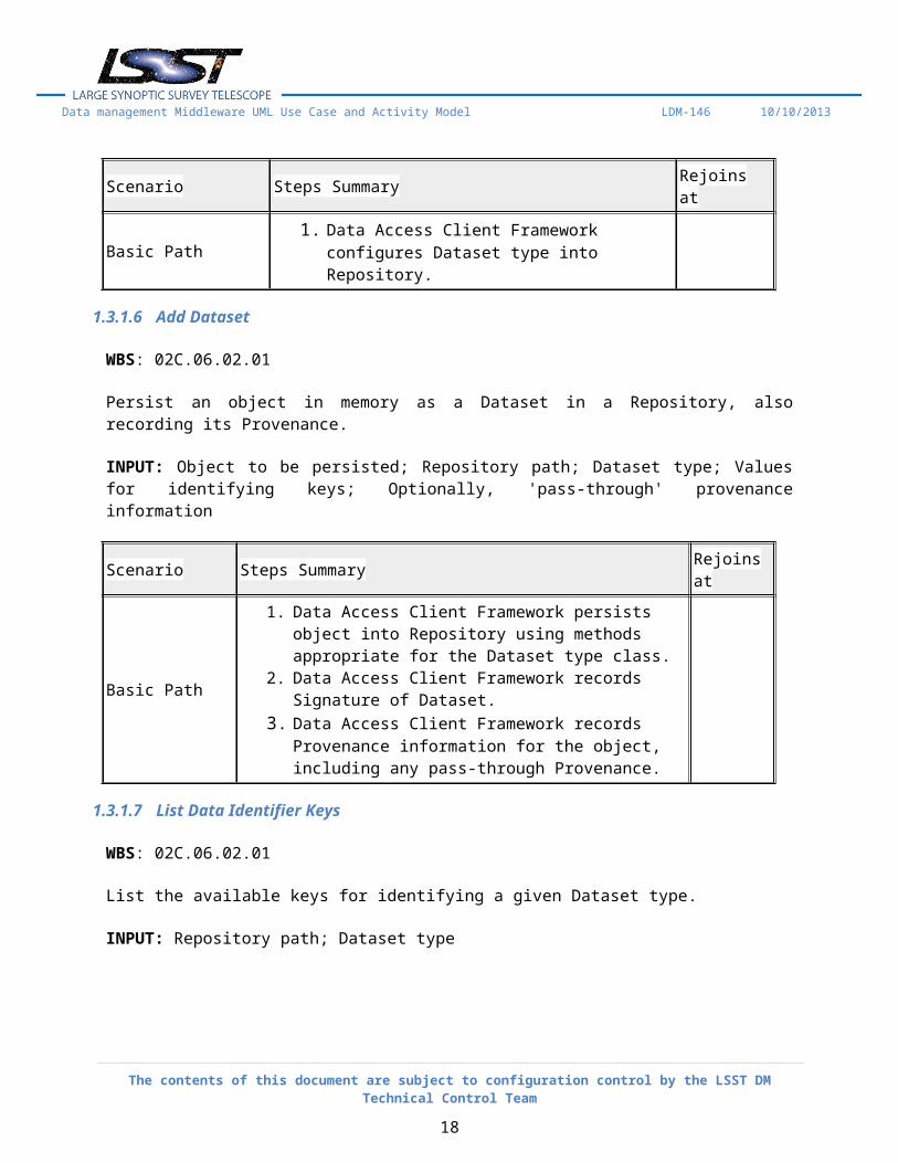
1.3.1.5 Add Dataset Type
WBS: 02C.06.02.01
Add a new dataset type to a Repository based on an existing dataset type class understood by the Repository's mapper class.
INPUT: Repository path; Dataset type name; Dataset type class ;Metadata required by the Dataset type class
Scenario Steps Summary Rejoins at
Basic Path 1. Data Access Client Framework configures Dataset type into Repository.
1.3.1.6 Add Dataset
WBS: 02C.06.02.01
The contents of this document are subject to configuration control by the LSST DM Technical Control Team
13
Data management Middleware UML Use Case and Activity Model LDM-146 10/10/2013
Persist an object in memory as a Dataset in a Repository, also recording its Provenance.
INPUT: Object to be persisted; Repository path; Dataset type; Values for identifying keys; Optionally, 'pass-through' provenance information
Scenario Steps Summary Rejoins at
Basic Path
1. Data Access Client Framework persists object into Repository using methods appropriate for the Dataset type class.
2. Data Access Client Framework records Signature of Dataset.3. Data Access Client Framework records Provenance
information for the object, including any pass-through Provenance.
1.3.1.7 List Data Identifier Keys
WBS: 02C.06.02.01
List the available keys for identifying a given Dataset type.
INPUT: Repository path; Dataset type
Scenario Steps Summary Rejoins at
Basic Path 1. Data Access Client Framework returns a list of identifying keys.
1.3.1.8 Remove Dataset
WBS: 02C.06.02.01
Remove a Dataset from a Repository.
INPUT: Repository path; Dataset type; Values for Identifying Keys
Scenario Steps Summary Rejoins at
Basic Path 1. Data Access Client Framework removes Dataset and Signature from Repository.
2. Data Access Client Framework marks the Dataset as being removed in its Provenance. (Note: provenance is not
The contents of this document are subject to configuration control by the LSST DM Technical Control Team
14
Data management Middleware UML Use Case and Activity Model LDM-146 10/10/2013
Scenario Steps Summary Rejoins at
removed.)
1.3.1.9 List Datasets
WBS: 02C.06.02.01
List available Datasets for a given Dataset type and optional identifying information.
INPUT: Repository path; Dataset type; Zero or more values for Identifying Keys
Scenario Steps Summary Rejoins at
Basic Path1. Data Access Client Framework returns Identifying Key value
sets describing each Dataset present in the Repository that match the given type and key values.
1.3.1.10 List Dataset Types
WBS: 02C.06.02.01
List the available Dataset types.
INPUT: Repository path
Scenario Steps Summary Rejoins at
Basic Path 1. Data Access Client Framework returns a list of available Dataset types.
1.3.2 Data Definition Client Services
WBS: 02C.06.02.02
These services are used to create schemas and tables within them for any of the databases used in the Science Data Archive or the temporary production catalogs.
1.3.2.1 Create Table
WBS: 02C.06.02.02
Create one or more Tables in a Database according to a pre-defined Schema.
The contents of this document are subject to configuration control by the LSST DM Technical Control Team
15
Data management Middleware UML Use Case and Activity Model LDM-146 10/10/2013
INPUT: Database; Table name(s); Schema handle(s)
Scenario Steps Summary Rejoins at
Basic Path 1. Data Definition Client Services creates Table(s) in the Database using the previously-defined Schema(s).
1.3.2.2 Define Schema
WBS: 02C.06.02.02
Define the Schema for one or more Tables in a Database.
INPUT: Table definitions, including column data types, indexes, etc.
Scenario Steps Summary Rejoins at
Basic Path1. Data Definition Client Services records Schema.2. Data Definition Client Services returns a handle to
the schema.
1.3.3 Query Services
WBS: 02C.06.02.03
The Query Services component performs scalable execution of SQL-dialect queries on vast amounts of data partitioned in chunks across a platform consisting of a cluster of machines.
1.3.3.1 Recognize Spatial SQL Extensions
WBS: 02C.06.02.03
Recognize syntax for Query Services extensions to SQL92 to handle spatial operations such as region restriction.
chunk.3. Query Services executes query against chunk and
returns
1.3.3.6 Recognize and Execute Scan Neighbor Queries
WBS: 02C.06.02.03
Recognize and execute queries that perform a full scan on a distributed table with a self-join to find pairs of rows within a certain radius.
INPUT: Scan neighbor query
Scenario Steps Summary Rejoins at
Basic Path 1. Query Services recognizes query type.2. Query Services directs query to all table chunks.3. Query Services executes query against all table
The contents of this document are subject to configuration control by the LSST DM Technical Control Team
18
Data management Middleware UML Use Case and Activity Model LDM-146 10/10/2013
Scenario Steps Summary Rejoins at
chunks and overlap segments.4. Query Services combines query results as needed and
returns result.
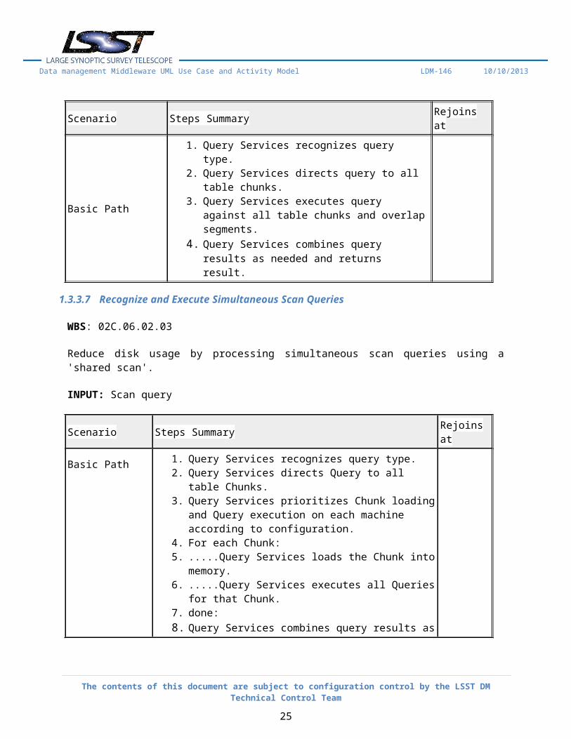
1.3.3.7 Recognize and Execute Simultaneous Scan Queries
WBS: 02C.06.02.03
Reduce disk usage by processing simultaneous scan queries using a 'shared scan'.
INPUT: Scan query
Scenario Steps Summary Rejoins at
Basic Path
1. Query Services recognizes query type.2. Query Services directs Query to all table Chunks.3. Query Services prioritizes Chunk loading and Query
execution on each machine according to configuration.4. For each Chunk:5. .....Query Services loads the Chunk into memory.6. .....Query Services executes all Queries for that Chunk.7. done:8. Query Services combines query results as needed for each
query separately and returns results.
1.3.3.8 Recognize and Execute Simple Scan Queries
WBS: 02C.06.02.03
Recognize and execute queries that perform a full scan on a distributed table without joins.
INPUT: Simple scan query
Scenario Steps Summary Rejoins at
Basic Path 1. Query Services recognizes query type.2. Query Services directs query to all table chunks.3. Query Services executes query against all table
chunks.4. Query Services combines query results as needed
The contents of this document are subject to configuration control by the LSST DM Technical Control Team
19
Data management Middleware UML Use Case and Activity Model LDM-146 10/10/2013
Scenario Steps Summary Rejoins at
and returns result.
1.3.3.9 Remove Table
WBS: 02C.06.02.03
Remove a distributed or replicated table.
INPUTS: Database name; Table name
Scenario Steps Summary Rejoins at
Basic Path 1. Query Services removes the table on each machine.
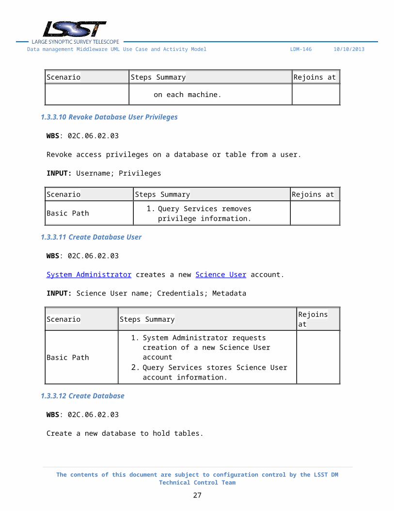
1.3.3.10 Revoke Database User Privileges
WBS: 02C.06.02.03
Revoke access privileges on a database or table from a user.
System Administrator creates a new Science User account.
INPUT: Science User name; Credentials; Metadata
Scenario Steps Summary Rejoins at
Basic Path 1. System Administrator requests creation of a new Science User account
The contents of this document are subject to configuration control by the LSST DM Technical Control Team
20
Data management Middleware UML Use Case and Activity Model LDM-146 10/10/2013
Scenario Steps Summary Rejoins at
2. Query Services stores Science User account information.
1.3.3.12 Create Database
WBS: 02C.06.02.03
Create a new database to hold tables.
INPUT: Database name
Scenario Steps Summary Rejoins at
Basic Path 1. Query Services creates the database.
1.3.3.13 Create Distributed User Table with Query Result
WBS: 02C.06.02.03
Store the results of a query in a user table, distributed in the same way as the original table(s).
INPUT: Table name within the user's database for the result; Query
Scenario Steps Summary Rejoins at
Basic Path
1. Query Services creates a distributed table to hold the result.
2. Query Services verifies that no combination of chunk results is required for the query.
3. Query Services directs query to appropriate chunks.4. For each chunk:5. .....Query Services executes query against chunk.6. .....Query Services loads the result data from chunk into
the distributed table.7. done:
1.3.3.14 Create Distributed Table
WBS: 02C.06.02.03
The contents of this document are subject to configuration control by the LSST DM Technical Control Team
21
Data management Middleware UML Use Case and Activity Model LDM-146 10/10/2013
Create a new (empty) table distributed across the Query Services cluster.
INPUT: Database name; Table name; Table definition, including partitioning and overlap
Scenario Steps Summary Rejoins at
Basic Path 1. Query Services creates empty tables for chunks on appropriate machines.
1.3.3.15 Abort Query
WBS: 02C.06.02.03
Science User-requested stop of an already-submitted query.
INPUT: Opaque Query Identifier; Science User name
Scenario Steps Summary Rejoins at
Basic Path
1. Science User requests 'Abort' of an already-submitted query.(see AltPath: Opaque Query Id provided is non-existant)
2. Query Services verifies that requesting user is the same as querying user or is a Database Administrator.(see AltPath: Requesting User is neither Querying User nor Database Administrator)
3. Query Services stops query execution on all machines and frees all associated resources.
4. fin:
AltPath: Opaque Query Id provided is non-existant 1. return error status to Science User
Basic Path step:4
AltPath: Requesting User is neither Querying User nor Database Administrator
1. Return error status to Science User Basic Path step:4
1.3.3.16 Abort Excessive Resource Query
WBS: 02C.06.02.03
The contents of this document are subject to configuration control by the LSST DM Technical Control Team
22
Data management Middleware UML Use Case and Activity Model LDM-146 10/10/2013
If a query execution exceeds the available resources for the querying Science User, abort the query.
INPUT: Query
Scenario Steps Summary Rejoins at
Basic Path
1. If: Query Services detects excessive resource usage by query(see AltPath: Query does not exceed max Resource Uage)
2. Query Services stops query execution on all machines and frees all associated resources except partial results.
3. Query Services logs the resource usage error.4. Query Services returns an error to the Science User.5. Query Services removes unretrieved partial results
after 24 hours.6. fin:
AltPath: Query does not exceed max Resource Uage
1. noop: Basic Path step:6
1.3.3.17 Create and Load Replicated Table
WBS: 02C.06.02.03
Create and load a small table replicated on all Query Services cluster machines.
INPUT: Data (stream, file, or file set) to be loaded; Data format; Database name; Table name; Table definition
Scenario Steps Summary Rejoins at
Basic Path
1. Query Services distributes data to all machines (can use a shared filesystem if available).
2. Query Services creates table on each machine.3. Query Services loads data into table.
1.3.3.18 Add New Machine to Query Services Platform
WBS: 02C.06.02.03
The contents of this document are subject to configuration control by the LSST DM Technical Control Team
23
Data management Middleware UML Use Case and Activity Model LDM-146 10/10/2013
System Administrator adds a new machine to an existing Query Services cluster. Replicas of existing chunks are migrated onto the machine.
INPUT: Identifier of a machine to be added that already has the Query Services worker components installed on it
Scenario Steps Summary Rejoins at
Basic Path
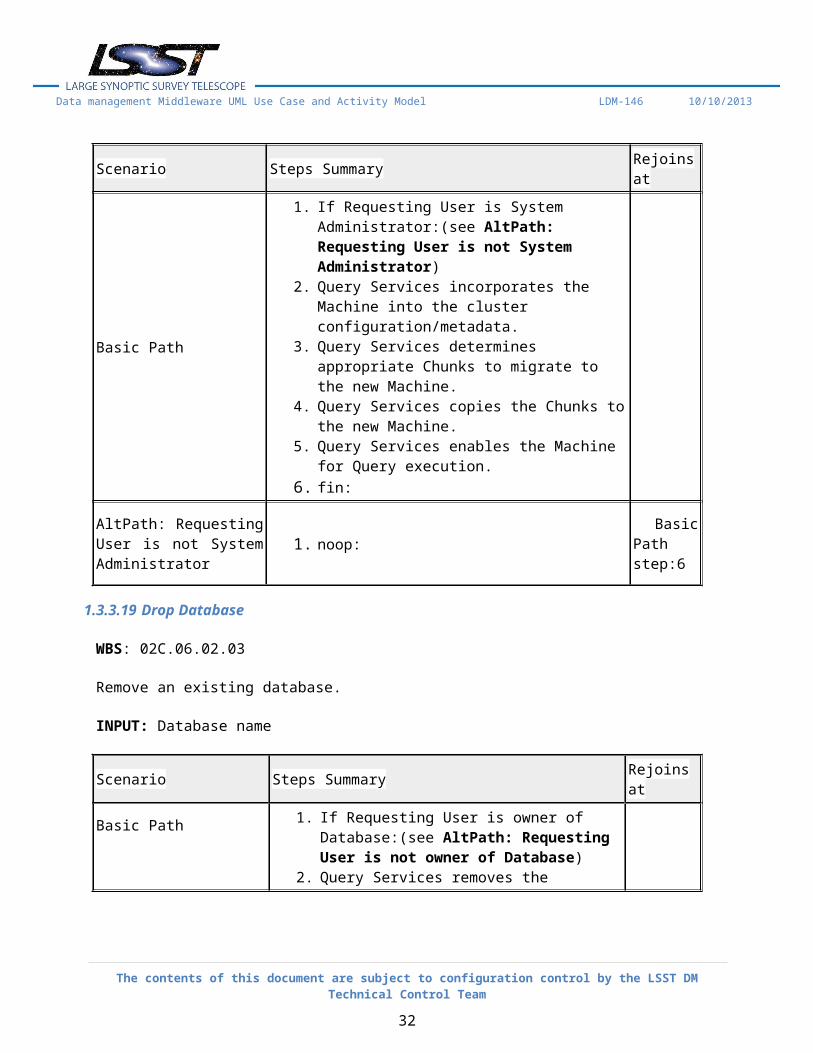
1. If Requesting User is System Administrator:(see AltPath: Requesting User is not System Administrator)
2. Query Services incorporates the Machine into the cluster configuration/metadata.
3. Query Services determines appropriate Chunks to migrate to the new Machine.
4. Query Services copies the Chunks to the new Machine.
5. Query Services enables the Machine for Query execution.
6. fin:
AltPath: Requesting User is not System Administrator 1. noop:
Basic Path step:6
1.3.3.19 Drop Database
WBS: 02C.06.02.03
Remove an existing database.
INPUT: Database name
Scenario Steps Summary Rejoins at
Basic Path
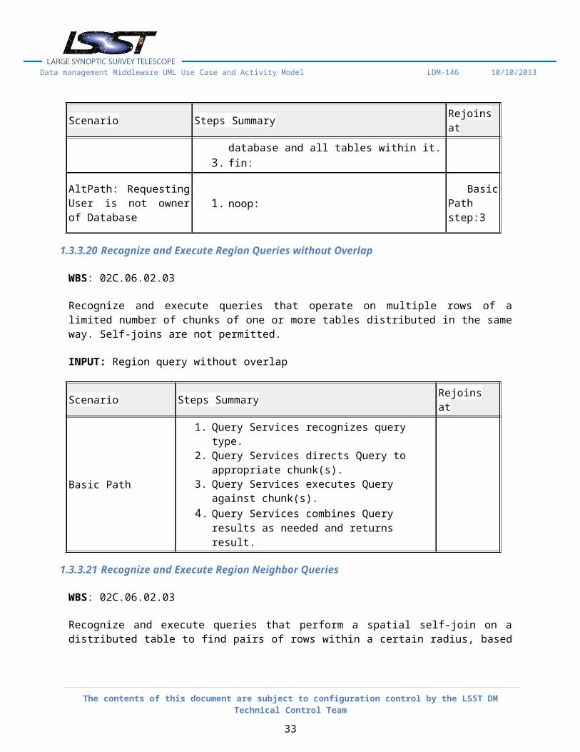
1. If Requesting User is owner of Database:(see AltPath: Requesting User is not owner of Database)
2. Query Services removes the database and all tables within it.
3. fin:
AltPath: Requesting User is 1. noop: Basic Path
The contents of this document are subject to configuration control by the LSST DM Technical Control Team
24
Data management Middleware UML Use Case and Activity Model LDM-146 10/10/2013
Scenario Steps Summary Rejoins at
not owner of Database step:3
1.3.3.20 Recognize and Execute Region Queries without Overlap
WBS: 02C.06.02.03
Recognize and execute queries that operate on multiple rows of a limited number of chunks of one or more tables distributed in the same way. Self-joins are not permitted.
chunk(s).3. Query Services executes Query against chunk(s).4. Query Services combines Query results as needed
and returns result.
1.3.3.21 Recognize and Execute Region Neighbor Queries
WBS: 02C.06.02.03
Recognize and execute queries that perform a spatial self-join on a distributed table to find pairs of rows within a certain radius, based on rows within a limited number of chunks.
and overlap segments.3. Query Services executes query against chunk(s) and
overlap segments.4. Query Services combines query results as needed and
returns result.
The contents of this document are subject to configuration control by the LSST DM Technical Control Team
25
Data management Middleware UML Use Case and Activity Model LDM-146 10/10/2013
1.3.3.22 Recognize and Execute Scan Join Queries
WBS: 02C.06.02.03
Recognize and execute queries that perform a full scan on a distributed table with joins to similarly-distributed tables or replicated tables.
INPUT: Scan join query
Scenario Steps Summary Rejoins at
Basic Path
1. Query Services recognizes query type.2. Query Services directs query to all table chunks.3. Query Services executes query against all table
chunks and replicated tables.4. Query Services combines query results as needed and
returns result.
1.3.3.23 Recognize and Execute Row Join Queries
WBS: 02C.06.02.03
Recognize and execute queries that operate on a single row of a table, identified by primary key, joined on foreign keys with one or more rows of one or more other tables distributed in the same way or replicated.
Estimate time and resource consumption for a query.
INPUT: Query using documented language constructs; Username
Scenario Steps Summary Rejoins at
Basic Path 1. Query Services returns estimated time and resource consumption.
1.3.3.26 Partition Data and Load Distributed Table
WBS: 02C.06.02.03
Partition data to be ingested and load it into a distributed table.
INPUT: Data (stream, file, or file set) to be loaded; Data format; Database name; Table name
Scenario Steps Summary Rejoins at
Basic Path
1. Query Services retrieves partitioning and overlap information for table.
2. Query Services partitions data into chunks and distributes chunks to appropriate machines.
3. Query Services loads data into chunk tables.
1.3.3.27 Install Query Services
WBS: 02C.06.02.03
Install the Query Services on a new machine or a cluster of machines.
INPUT: One or more machine identifiers; Query Services configuration
The contents of this document are subject to configuration control by the LSST DM Technical Control Team
27
Data management Middleware UML Use Case and Activity Model LDM-146 10/10/2013
Scenario Steps Summary Rejoins at
Basic Path
1. Query Services installs the master components on machines specified by the configuration.
2. Query Services installs the worker components on machines specified by the configuration.
3. Query Services configures itself.
1.3.3.28 Return Partial Query Result
WBS: 02C.06.02.03
Return partial results from an already-submitted query.
INPUT: Opaque query identifier
Scenario Steps Summary Rejoins at
Basic Path
1. Science User connects to Query Services through published API.
2. Science User requests partial result using opaque query identifier.
3. Query Services verifies that requesting user is the same as querying user.
4. Query Services returns current query status (waiting, executing, error).
5. Query Services returns partial result as combined from completed chunks.
6. If Query Status either 'Waiting' or 'Executing':(see Alt Path: Query had aborted in error)
7. fin:
Alt Path: Query had aborted in error 1. Query Services removes partial results
Basic Path step:7
1.3.3.29 Submit SQL-Like Query
WBS: 02C.06.02.03
Submit a query to Query Services using a language based on SQL92 with some restrictions and some extensions.
The contents of this document are subject to configuration control by the LSST DM Technical Control Team
28
Data management Middleware UML Use Case and Activity Model LDM-146 10/10/2013
INPUT: Query using documented language constructs; Username
Scenario Steps Summary Rejoins at
Basic Path
1. Science User writes query using documented language constructs.
2. Science User connects to Query Services through published API (from a program or provided client).
3. Science User submits query.4. Query Services returns an opaque query identifier.5. If Query Services recognizes the query:(see AltPath:
Query not recognized, not executable, or failed during execution)
6. If Query Services verifies that the Query is executable, i.e. the user has sufficient privileges and resources to execute the query:(see AltPath: Query not recognized, not executable, or failed during execution)
7. Query Services attempts to execute the query.8. If Query executes successfully:(see AltPath: Query not
recognized, not executable, or failed during execution)9. Query Services returns query results.10. fin:
AltPath: Query not recognized, not executable, or failed during execution
1. Query Services returns an error code and message. Basic Path step:10
1.3.3.30 Return Query Results in Parallel
WBS: 02C.06.02.03
Return the results of a query via multiple parallel streams.
Scenario Steps Summary Rejoins at
Basic Path 1. Science User specifies a query, indicating that parallel results are desired.
2. If Query Services verifies that no combination of chunk results is required for the query:(see Alt Path: A combination of chunk results is required for the query)
The contents of this document are subject to configuration control by the LSST DM Technical Control Team
29
Data management Middleware UML Use Case and Activity Model LDM-146 10/10/2013
Scenario Steps Summary Rejoins at
3. Query Services directs query to appropriate chunks.4. For each machine executing the query:5. .....Query Services creates a result stream. 6. done:7. For each chunk processed by the query on the
machine:8. .....Query Services executes query against chunk.9. .....Query Services returns the result data from chunk
on the result stream.10. While the query is not complete:11. .....Science User connects to Query Services through
published API.12. .....Science User requests the next result stream using
the opaque query identifier.13. ..... Query Services returns the next result stream and
returns result data from a machine on that stream.14. done:15. fin:
Alt Path: A combination of chunk results is required for the query
1. Query Services returns an error that a combination of chunk results would be required.
Basic Path step:15
1.3.4 Image and File Services
WBS: 02C.06.02.04
These services perform image processing in order to regenerate virtual image data products and to generate images of spatial regions of interest (both large mosaics and small postage stamps). In addition, Image and File Services manages caches of files and images to speed up retrieval.
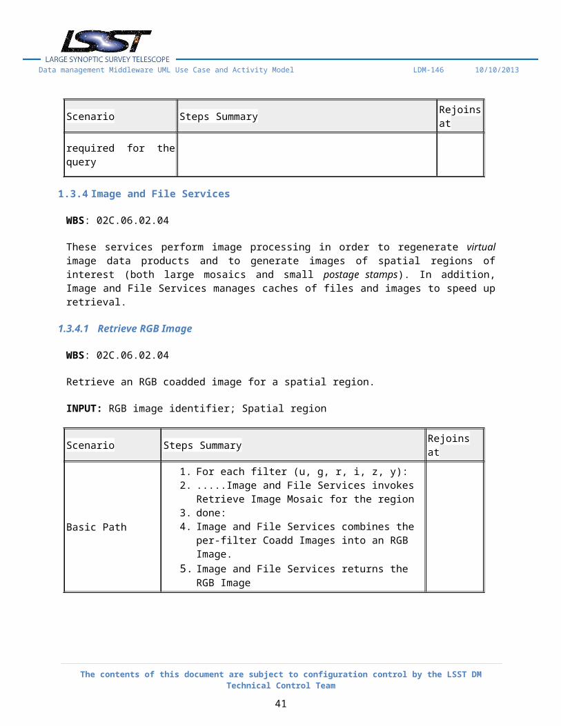
1.3.4.1 Retrieve RGB Image
WBS: 02C.06.02.04
Retrieve an RGB coadded image for a spatial region.
INPUT: RGB image identifier; Spatial region
The contents of this document are subject to configuration control by the LSST DM Technical Control Team
30
Data management Middleware UML Use Case and Activity Model LDM-146 10/10/2013
Scenario Steps Summary Rejoins at
Basic Path
1. For each filter (u, g, r, i, z, y):2. .....Image and File Services invokes Retrieve Image
Mosaic for the region3. done:4. Image and File Services combines the per-filter Coadd
Images into an RGB Image.5. Image and File Services returns the RGB Image
1.3.4.2 Retrieve Calibrated Science Image
WBS: 02C.06.02.04
Retrieve a calibrated science image from cache or regenerate one on the fly.
INPUT: Calibrated science image unique identifier, spatial and temporal coordinates, or other identifying information
Scenario Steps Summary Rejoins at
Basic Path
1. Image and File Services checks Calibrated Science Image Cache for presence of Image.
2. If Image is not in Calibrated Science Image Cache:(see AltPath: Image is in Calibrated Science Image Cache)
3. Image and File Services retrieves corresponding Raw Images and Master Calibration Images.
4. Image and File Services invokes Application Framework to reduce and calibrate Image.
5. Image and File Services caches resulting Calibrated Science Image.
6. fin:
AltPath: Image is in Calibrated Science Image Cache
1. noop: Basic Path step:6
1.3.4.3 Regenerate FITS File
WBS: 02C.06.02.04
The contents of this document are subject to configuration control by the LSST DM Technical Control Team
31
Data management Middleware UML Use Case and Activity Model LDM-146 10/10/2013
Combine metadata from database with FITS file in repository and return to Science User.
INPUT: Unique image identifier; spatial and temporal coordinates; or other identifying information
Scenario Steps Summary Rejoins at
Basic Path
1. Image and File Services invokes Data Access Client Framework: Retrieve Dataset to retrieve image.
2. Image and File Services invokes Data Access Client Framework: Retrieve Dataset to retrieve image metadata.
3. Image and File Services converts metadata into FITS headers and combines with image.
4. Image and File Services returns FITS file to user
1.3.4.4 Retrieve Cutout Image
WBS: 02C.06.02.04
Retrieve a cutout (postage stamp) of a calibrated science image.
INPUT: Calibrated science image identifier; Spatial region
Scenario Steps Summary Rejoins at
Basic Path
1. Image and File Services invokes Retrieve Calibrated Science Image.
2. Image and File Services trims the image to the desired spatial region.
3. Image and File Services returns the cutout.
1.3.4.5 Retrieve Image Mosaic
WBS: 02C.06.02.04
Retrieve a mosaic of coadded images for a spatial region.
INPUT: Coadd image identifiers; Spatial region
Scenario Steps Summary Rejoins at
Basic Path 1. Image and File Services invokes Data Access Client Framework: Retrieve Dataset to retrieve coadd images
The contents of this document are subject to configuration control by the LSST DM Technical Control Team
32
Data management Middleware UML Use Case and Activity Model LDM-146 10/10/2013
Scenario Steps Summary Rejoins at
covering the spatial region.2. Image and File Services combines the coadd images into a
mosaic.3. Image and File Services trims the mosaic to the desired
spatial region.4. Image and File Services returns the mosaic image
1.3.4.6 Retrieve Difference Image
WBS: 02C.06.02.04
Retrieve a difference image from cache or regenerate one on the fly.
INPUT: Difference image unique identifier, spatial and temporal coordinates, or other identifying information
Scenario Steps Summary Rejoins at
Basic Path
1. Image and File Services checks difference image cache for presence of image.
2. If Difference Image is not present:(see AltPath: Difference Image is present in Difference Image Cache)
3. Image and File Services invokes Retrieve Calibrated Science Image.
4. Image and File Services retrieves latest version of template image for the year of the calibrated science image.
5. Image and File Services invokes Application Framework to perform image differencing.
6. Image and File Services caches resulting difference image
7. fin:
AltPath: Difference Image is present in Difference Image Cache
1. noop: Basic Path step:7
The contents of this document are subject to configuration control by the LSST DM Technical Control Team
33
Data management Middleware UML Use Case and Activity Model LDM-146 10/10/2013
1.4 Pipeline Execution Services
WBS: 02C.06.03
These services provide portable, astronomy-optimized services to applications pipelines to enable their organization, logging, communication, and fault tolerance.
1.4.1 Pipeline Construction Toolkit
WBS: 02C.06.03.01
The Pipeline Construction Toolkit enables application developers to create tasks to perform operations and execute algorithms within the LSST DM stack framework. Tasks may be nested hierarchically. Each task has a configuration that controls its execution.
1.4.1.1 Validate Task Configuration
WBS: 02C.06.03.01
Task configuration parameters are validated after all overrides are performed.
Scenario Steps Summary Rejoins at
Basic Path
1. Pipeline Construction Toolkit calls the validation method for each field after all overrides have been performed.
2. If No Task Configuration validation failures occured:(see AltPath: Task Configuration validation failures occurred)
1. Pipeline Construction Toolkit reports validation failures and terminates task execution.
Basic Path step:3
1.4.1.2 Set Task Metadata Item
WBS: 02C.06.03.01
While a task is executing, it may set items in the processing metadata that is persisted when the task completes.
INPUT: Key and value for the processing metadata item
The contents of this document are subject to configuration control by the LSST DM Technical Control Team
34
Data management Middleware UML Use Case and Activity Model LDM-146 10/10/2013
Scenario Steps Summary Rejoins at
Basic Path1. Pipeline Construction Toolkit saves the key and value in the
processing metadata. If the key already exists, the value is appended to the current one.
1.4.1.3 Print Task Configuration Documentation
WBS: 02C.06.03.01
User-friendly documentation can be extracted from task configurations.
INPUT: Configuration documentation request argument; Selector for extraction before execution or after overrides and validation have been applied
Scenario Steps Summary Rejoins at
Basic Path1. Pipeline Construction Toolkit outputs parameter names,
documentation strings, types, and default values for all parameters in the task configuration
1.4.1.4 Print Task Configuration History
WBS: 02C.06.03.01
The history of all changes to configuration parameters can be extracted from a task configuration.
INPUT: Configuration history request argument.
Scenario Steps Summary Rejoins at
Basic Path
1. Pipeline Construction Toolkit outputs parameter names, default values, and all subsequent override values for all parameters in the task configuration after overrides and validation have been applied
1.4.1.5 Persist Task Configuration
WBS: 02C.06.03.01
The task configuration is persisted to a dataset.
The contents of this document are subject to configuration control by the LSST DM Technical Control Team
35
Data management Middleware UML Use Case and Activity Model LDM-146 10/10/2013
Scenario Steps Summary Rejoins at
Basic Path1. After the task configuration is frozen, Pipeline Construction
Toolkit persists it as used (not necessarily including history) to a dataset
1.4.1.6 Define Task Inputs and Outputs
WBS: 02C.06.03.01
Tasks provide information about the inputs they expect and the outputs they will produce to enable staging of data and better usability for science users.
INPUTS: Task input and output definitions by dataset type, indicating which inputs share data identifiers
Scenario Steps Summary Rejoins at
Basic Path 1. Pipeline Construction Toolkit arranges to return a list of data references to the input datasets when the task is executed
1.4.1.7 Execute Task in Parallel on One Machine
WBS: 02C.06.03.01
Run a task in parallel fashion, processing multiple data items at the same time, on one machine.
INPUT: Task; Command-line arguments (including configuration parameter overrides); Number of processes to use on the single machine; Repositories and data identifiers for input data
Scenario Steps Summary Rejoins at
Basic Path 1. If No Task Configuration override necessary from Arguments:(see AltPath: Override Task Configuration from Arguments)
2. If No Task Configuration override necessary from File:(see AltPath: Override Task Configuration from File)
3. Pipeline Construction Toolkit invokes Validate Task Configuration.
4. Pipeline Construction Toolkit invokes Freeze Task Configuration,.
5. Pipeline Construction Toolkit Persist Task
The contents of this document are subject to configuration control by the LSST DM Technical Control Team
36
Data management Middleware UML Use Case and Activity Model LDM-146 10/10/2013
Scenario Steps Summary Rejoins at
Configuration.6. For each input data identifier:7. .....Pipeline Construction Toolkit spawns a new
process to execute the task on that input dataset.8. done:9. Pipeline Construction Toolkit persists the processing
metadata resulting from executing the task
AltPath: Override Task Configuration from Arguments
1. Pipeline Construction Toolkit invokes: Override Task Configuration from Arguments
Basic Path step:2
AltPath: Override Task Configuration from File
1. Pipeline Construction Toolkit invokes: Override Task Configuration from File
Basic Path step:3
1.4.1.8 Define Task Arguments
WBS: 02C.06.03.01
Tasks can accept arguments on the command line to specify information such as database connection parameters. All such arguments must be of simple types (e.g. strings, numbers).
INPUT: Task arguments, including name, type, and documentation string
Scenario Steps Summary Rejoins at
Basic Path1. Pipeline Construction Toolkit arranges for arguments to be
recognized on the command line and passed to the task when it is executed
1.4.1.9 Define Task Configuration
WBS: 02C.06.03.01
The configuration for a task is defined by a class containing instances of Fields representing configuration parameters of various types: Simple value, Choice, List, Range, Nested configuration, Configurable algorithm.
Each field has a required documentation string and may be associated with a default value and validation method. All fields maintain the complete history of changes to their values.
The contents of this document are subject to configuration control by the LSST DM Technical Control Team
37
Data management Middleware UML Use Case and Activity Model LDM-146 10/10/2013
INPUT: Task configuration parameters, including name, type, documentation string, default value, and validation method
Scenario Steps Summary Rejoins at
Basic Path 1. Pipeline Construction Toolkit verifies all required definition information is present
1.4.1.10 Override Task Configuration from Arguments
WBS: 02C.06.03.01
Task configuration parameters may be overridden at execution time by values taken from the command line.
INPUT: Override arguments on the task command line
Scenario Steps Summary Rejoins at
Basic Path
1. Pipeline Construction Toolkit uses the values for the configuration parameters from the command line after any file overrides, recording the changes in the histories of each changed
1.4.1.11 Override Task Configuration from File
WBS: 02C.06.03.01
Task configuration parameters may be overridden at execution time by values taken from a file.
INPUT: Name for the task
Scenario Steps Summary Rejoins at
Basic Path
1. When the task is executed, Pipeline Construction Toolkit searches a pre-defined set of locations for override files with the same name as the task.
2. If Override file is found:(see AltPath: No Override File found)3. Pipeline Construction Toolkit uses the values for the
configuration parameters from the override file, recording the changes in the histories of each changed field
4. fin:
The contents of this document are subject to configuration control by the LSST DM Technical Control Team
38
Data management Middleware UML Use Case and Activity Model LDM-146 10/10/2013
Scenario Steps Summary Rejoins at
AltPath: No Override File found
1. noop: Basic Path step:4
1.4.1.12 Execute Task Serially
WBS: 02C.06.03.01
; Run a task in serial fashion, processing multiple data items in sequence.
INPUT: Task; Command-line arguments (including configuration parameter overrides); Repositories and data identifiers for input data
Scenario Steps Summary Rejoins at
Basic Path
1. If No Task Configuration override necessary from Arguments:(see AltPath: Override Task Configuration from Arguments)
2. If No Task Configuration override necessary from File:(see AltPath: Override Task Configuration from File)
3. Pipeline Construction Toolkit invokes Validate Task Configuration.
5. Pipeline Construction Toolkit invokes Persist Task Configuration.
6. For each input data identifier:7. .....Pipeline Construction Toolkit executes the task on
that input dataset.8. done:9. Pipeline Construction Toolkit persists the processing
metadata resulting from executing the
AltPath: Override Task Configuration from File
1. Pipeline Construction Toolkit invokes: Override Task Configuration from File
Basic Path step:3
AltPath: Override Task Configuration from
1. Pipeline Construction Toolkit invokes Override Task Configuration from Arguments
Basic Path step:2
The contents of this document are subject to configuration control by the LSST DM Technical Control Team
39
Data management Middleware UML Use Case and Activity Model LDM-146 10/10/2013
Scenario Steps Summary Rejoins at
Arguments
1.4.1.13 Freeze Task Configuration
WBS: 02C.06.03.01
Task configuration parameters are frozen (made unchangeable) after validation.
Scenario Steps Summary Rejoins at
Basic Path 1. Pipeline Construction Toolkit disables changes for all configuration parameters after validation has occurred
1.4.2 Logging Services
WBS: 02C.06.03.02
The Logging Services enable tasks to produce log entries, including fatal errors, warnings, and debugging messages. Log entries may be sent to a variety of destinations including standard streams, files, and the Event Services broker. Each entry may have metadata associated with it. An external configuration specifies which entries go to which destinations with which message format.
1.4.2.1 Define Log Message Format
WBS: 02C.06.03.02
Log entries can be formatted into text strings, incorporating per-message and common metadata items.
INPUT: Log message format using specified substitution syntax
Scenario Steps Summary Rejoins at
Basic Path 1. Logging Services formats messages according to the configured log message format
1.4.2.2 Create Log Entry
WBS: 02C.06.03.02
Create an entry in the log.
The contents of this document are subject to configuration control by the LSST DM Technical Control Team
40
Data management Middleware UML Use Case and Activity Model LDM-146 10/10/2013
1. Logging Services transmits the message and the per-message and common metadata, formatted according to the configured message format, to all selected destinations. (Depending on thresholds, there may be no selected destinations.)
1.4.2.3 Configure Logging Services
WBS: 02C.06.03.02
Each component name and hierarchically-defined groups of component names can be associated with logging thresholds, log destinations, and log message formats via an external text file.
INPUT: Logging Services configuration, comprising an association between a component name or group of components, a logging threshold, zero or more log destinations, and log message format(s) (up to one per component/threshold/destination combination)
Scenario Steps Summary Rejoins at
Basic Path1. Logging Services configures itself to send messages for the
components that meet the threshold to the destinations with the formats given
1.4.2.4 Create Log Object
WBS: 02C.06.03.02
The Log object is the interface used to create log entries and define metadata.
INPUT: Component name
Scenario Steps Summary Rejoins at
Basic Path 1. Logging Services returns a Log object.
1.4.2.5 Define Log Destination
WBS: 02C.06.03.02
The contents of this document are subject to configuration control by the LSST DM Technical Control Team
41
Data management Middleware UML Use Case and Activity Model LDM-146 10/10/2013
Create a destination for log entries.
INPUT: Log entry handler using a specified API
Scenario Steps Summary Rejoins at
Basic Path 1. Logging Services enables the sending of log entries to the log entry handler.
1.4.2.6 Define Common Log Metadata
WBS: 02C.06.03.02
Metadata common to all entries logged by a Log object can be set.
INPUT:; Log object; Key/value pairs
Scenario Steps Summary Rejoins at
Basic Path 1. Logging Services records the keys and values and uses them for all subsequent messages sent by that Log object.
1.4.3 Inter-Process Messaging Services
WBS: 02C.06.03.03
The Inter-Process Messaging Services enable tasks to send and receive data items according to a defined communications geometry (e.g. broadcast/scatter from each task to all others, gather from all tasks to a designated one, exchange data with neighbors in a grid). A variety of communications mechanisms (e.g. MPI or the LSST DM Event Services) are supported with the same interface.
1.4.3.1 Initialize Inter-Process Task and Execute
WBS: 02C.06.03.03
Tasks that use inter-process messaging must be identified as such so that the communications mechanism can be initialized properly and the task executed in the proper context.
INPUT: Task marked as using Inter-Process Messaging Services
The contents of this document are subject to configuration control by the LSST DM Technical Control Team
42
Data management Middleware UML Use Case and Activity Model LDM-146 10/10/2013
Scenario Steps Summary Rejoins at
Basic Path
1. Inter-Process Messaging Services obtains information from the environment or an external configuration file defining the communications mechanism to use and the available communication partners.
2. Inter-Process Messaging Services initializes the selected communications mechanism for the task.
3. Inter-Process Messaging Services executes the task within the appropriate context for the selected communications mechanism.
1.4.3.2 Define Communications Geometry
WBS: 02C.06.03.03
Tasks using inter-process messaging define one or more communications geometries.
INPUT: Communications geometry specified according to the API provided
Scenario Steps Summary Rejoins at
Basic Path
1. Inter-Process Messaging Services determines which other task executions are to be communicated with.
2. Inter-Process Messaging Services performs any setup required by the selected communications mechanism to communicate with those task executions.
1.4.3.3 Send Data Item(s)
WBS: 02C.06.03.03
Send one or more data items via the communications geometry.
INPUT: One or more data items, all of which are serializable; One or more destinations selected from the communications geometry (different sets of data items can be sent to each destination)
Scenario Steps Summary Rejoins at
Basic Path 1. Inter-Process Messaging Services serializes the data items and transmits them via the communications mechanism to the remote
The contents of this document are subject to configuration control by the LSST DM Technical Control Team
43
Data management Middleware UML Use Case and Activity Model LDM-146 10/10/2013
Scenario Steps Summary Rejoins at
task execution(s). The communications mechanism is expected to buffer the data items as necessary.
2. Inter-Process Messaging Services returns when the data items have been sent, not when they have been received, helping to avoid deadlock.
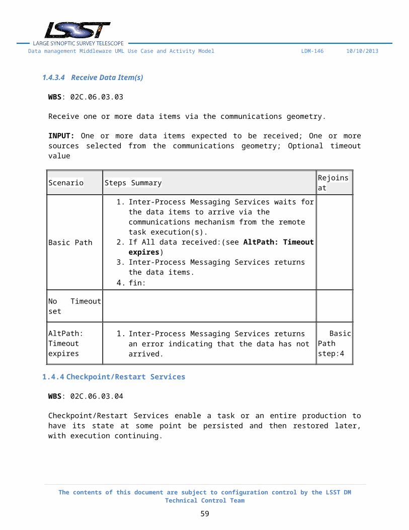
1.4.3.4 Receive Data Item(s)
WBS: 02C.06.03.03
Receive one or more data items via the communications geometry.
INPUT: One or more data items expected to be received; One or more sources selected from the communications geometry; Optional timeout value
Scenario Steps Summary Rejoins at
Basic Path
1. Inter-Process Messaging Services waits for the data items to arrive via the communications mechanism from the remote task execution(s).
2. If All data received:(see AltPath: Timeout expires)3. Inter-Process Messaging Services returns the data items.4. fin:
No Timeout set
AltPath: Timeout expires
1. Inter-Process Messaging Services returns an error indicating that the data has not arrived.
Basic Path step:4
1.4.4 Checkpoint/Restart Services
WBS: 02C.06.03.04
Checkpoint/Restart Services enable a task or an entire production to have its state at some point be persisted and then restored later, with execution continuing.
1.4.4.1 Restart Pipeline from Checkpoint
WBS: 02C.06.03.04
The contents of this document are subject to configuration control by the LSST DM Technical Control Team
44
Data management Middleware UML Use Case and Activity Model LDM-146 10/10/2013
Given a handle to a checkpoint of a task, restart the task.
INPUT: Task; Checkpoint handle as an argument
ALGORITHM:
Checkpoint/Restart Services locates the task state and calls the method for restoring state.
Scenario Steps Summary Rejoins at
Basic Path 1. Checkpoint/Restart Services locates the task state and calls the method for restoring state.
1.4.4.2 Define Pipeline Checkpoint
WBS: 02C.06.03.04
The task defines appropriate places to checkpoint itself. The implementation may require that the task provide methods to save its state and restore itself from saved state.
INPUT: Task marked with location(s) for a checkpoint; Methods for saving and restoring state
ALGORITHM:
Checkpoint/Restart Services persists the task state when the location is reached, assigning an opaque handle and recording the handle.
Scenario Steps Summary Rejoins at
Basic Path1. Checkpoint/Restart Services persists the task state when the
location is reached, assigning an opaque handle and recording the handle.
1.4.4.3 Restart Production from Checkpoint
WBS: 02C.06.03.04
Restart a production phase from a checkpoint.
INPUTS: Checkpoint handle
ALGORITHM:
The contents of this document are subject to configuration control by the LSST DM Technical Control Team
45
Data management Middleware UML Use Case and Activity Model LDM-146 10/10/2013
Checkpoint/Restart Services invokes the Orchestration Manager to complete the unexecuted tasks on unprocessed datasets.
Scenario Steps Summary Rejoins at
Basic Path1. Checkpoint/Restart Services invokes the Orchestration
Manager to complete the unexecuted tasks on unprocessed datasets.
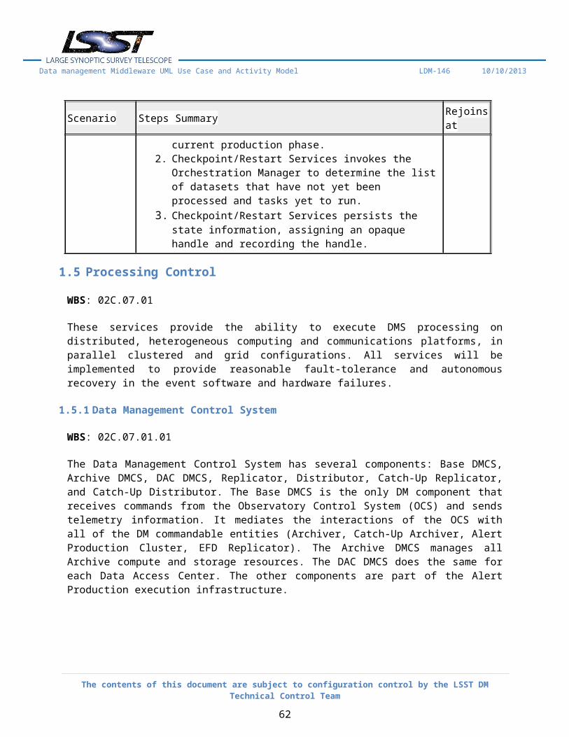
1.4.4.4 Define Production Checkpoint
WBS: 02C.06.03.04
Create a snapshot of the state of a production phase.
Scenario Steps Summary Rejoins at
Basic Path
1. Production Coordinator executes a command to save a snapshot of the state of the current production phase.
2. Checkpoint/Restart Services invokes the Orchestration Manager to determine the list of datasets that have not yet been processed and tasks yet to run.
3. Checkpoint/Restart Services persists the state information, assigning an opaque handle and recording the handle.
1.5 Processing Control
WBS: 02C.07.01
These services provide the ability to execute DMS processing on distributed, heterogeneous computing and communications platforms, in parallel clustered and grid configurations. All services will be implemented to provide reasonable fault-tolerance and autonomous recovery in the event software and hardware failures.
1.5.1 Data Management Control System
WBS: 02C.07.01.01
The Data Management Control System has several components: Base DMCS, Archive DMCS, DAC DMCS, Replicator, Distributor, Catch-Up Replicator, and Catch-Up Distributor. The Base DMCS is the only DM component that receives commands from the Observatory Control System (OCS) and sends telemetry information. It mediates the interactions of the OCS with all of the DM commandable entities (Archiver,
The contents of this document are subject to configuration control by the LSST DM Technical Control Team
46
Data management Middleware UML Use Case and Activity Model LDM-146 10/10/2013
Catch-Up Archiver, Alert Production Cluster, EFD Replicator). The Archive DMCS manages all Archive compute and storage resources. The DAC DMCS does the same for each Data Access Center. The other components are part of the Alert Production execution infrastructure.
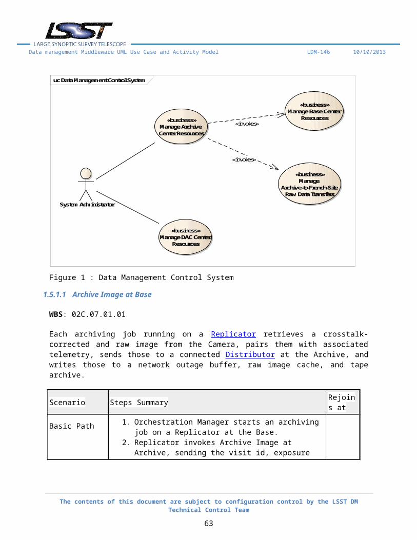
uc Data Management Control System
«business»Manage Archive Center Resources
«business»Manage
Archive-to-French-Site Raw Data Transfers
«business»Manage Base Center
Resources
«business»Manage DAC Center
Resources
System Administrator
«invokes»
«invokes»
Figure 1 : Data Management Control System
1.5.1.1 Archive Image at Base
WBS: 02C.07.01.01
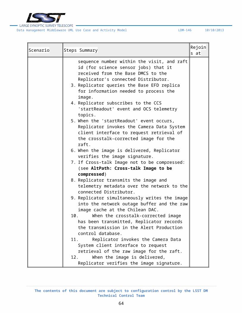
Each archiving job running on a Replicator retrieves a crosstalk-corrected and raw image from the Camera, pairs them with associated telemetry, sends those to a connected Distributor at the Archive, and writes those to a network outage buffer, raw image cache, and tape archive.
Scenario Steps Summary Rejoins at
Basic Path 1. Orchestration Manager starts an archiving job on a Replicator at the Base.
2. Replicator invokes Archive Image at Archive, sending the visit id, exposure sequence number within the visit, and raft id (for science sensor jobs) that it received from the Base DMCS to
The contents of this document are subject to configuration control by the LSST DM Technical Control Team
47
Data management Middleware UML Use Case and Activity Model LDM-146 10/10/2013
Scenario Steps Summary Rejoins at
the Replicator's connected Distributor.3. Replicator queries the Base EFD replica for information
needed to process the image.4. Replicator subscribes to the CCS 'startReadout' event and OCS
telemetry topics.5. When the 'startReadout' event occurs, Replicator invokes the
Camera Data System client interface to request retrieval of the crosstalk-corrected image for the raft.
6. When the image is delivered, Replicator verifies the image signature.
7. If Cross-talk Image not to be compressed:(see AltPath: Cross-talk Image to be compressed)
8. Replicator transmits the image and telemetry metadata over the network to the connected Distributor.
9. Replicator simultaneously writes the image into the network outage buffer and the raw image cache at the Chilean DAC.
10. When the crosstalk-corrected image has been transmitted, Replicator records the transmission in the Alert Production control database.
11. Replicator invokes the Camera Data System client interface to request retrieval of the raw image for the raft.
12. When the image is delivered, Replicator verifies the image signature.
13. If Raw Image not to be compressed:(see AltPath: Raw Image to be compressed)
14. Replicator transmits the image over the network to the connected Distributor.
15. Replicator simultaneously writes the image into the network outage buffer and tape archive.
16. When the raw image has been transmitted, Replicator records the transmission in the Alert Production control database.
AltPath: Cross-talk Image to be compressed
1. Replicator compresses the image Basic Path step:8
AltPath: Raw Image to be compressed
1. Replicator compresses the Raw Image Basic Path step:14
The contents of this document are subject to configuration control by the LSST DM Technical Control Team
48
Data management Middleware UML Use Case and Activity Model LDM-146 10/10/2013
1.5.1.2 Archive Image at Archive
WBS: 02C.07.01.01
Each Distributor paired with a Replicator receives images and metadata from the Replicator, distributes CCD portions of them to requesting machines, and writes them to a raw image cache and tape archive.
Scenario Steps Summary Rejoins at
Basic Path
1. Replicator sends visit id, exposure sequence number within the visit, and raft id (for science sensor jobs) to its connected Distributor.
2. Distributor invokes Event Services: Publish Event to publish visit id, exposure sequence number, and raft id to the Archive DMCS.
3. Distributor accepts requests for CCDs for the published Event visit.
4. Distributor receives crosstalk-corrected image and associated telemetry metadata from the Replicator.
5. Distributor verifies the image signature.6. Distributor decompresses the image if so configured.7. Distributor separates the image into CCDs.8. Distributor fulfills CCD image requests.9. Simultaneously, Distributor writes the image into the raw
image cache at the US DAC.10. Distributor receives raw image and associated telemetry
metadata from the Replicator.11. Distributor verifies the image signature.12. Distributor writes the image into the tape archive.
1.5.1.3 Manage Archive-to-French-Site Data Release Data Transfers
WBS: 02C.07.01.01
The Archive DMCS is responsible for managing transfers of Data Release intermediate products and Level 2 data products from the Archive to and from the French Site.
INPUT: Identification of intermediate or final data products to be transferred
Scenario Steps Summary Rejoins at
Basic Path 1. Archive DMCS invokes File System Services to replicate
The contents of this document are subject to configuration control by the LSST DM Technical Control Team
49
Data management Middleware UML Use Case and Activity Model LDM-146 10/10/2013
Scenario Steps Summary Rejoins at
the data to the other site.
1.5.1.4 Manage Production Phase Execution at Archive
WBS: 02C.07.01.01
The Archive DMCS is responsible for managing execution of tasks for the Calibration Productions Production (in its daily, monthly, and annual incarnations) and each phase of the annual Data Release Production.
INPUT: Tasks to be executed; Dependencies between tasks; Data to be processed; Units of data processing (e.g. sky tiles); Values for all (non-default) configuration parameters
Scenario Steps Summary Rejoins at
Basic Path
1. Archive DMCS records system software state.2. For each data processing unit:3. .....Archive DMCS invokes Orchestration Manager to
execute specified tasks according to dependencies.4. .....Archive DMCS monitors and reports both progress and
results.5. done:
1.5.1.5 Respond to Alert Production Cluster disable Command at Base
WBS: 02C.07.01.01
The Base DMCS responds to disable commands from the OCS for the Alert Production Cluster commandable entity by removing the subscription to the nextVisit event.
INPUT: disable command from OCS for the Alert Production Cluster
Scenario Steps Summary Rejoins at
Basic Path 1. Base DMCS unsubscribes from the nextVisit event.
1.5.1.6 Respond to Alert Production Cluster enable Command at Base
WBS: 02C.07.01.01
The contents of this document are subject to configuration control by the LSST DM Technical Control Team
50
Data management Middleware UML Use Case and Activity Model LDM-146 10/10/2013
The Base DMCS responds to enable commands from the OCS for the Alert Production Cluster commandable entity by subscribing to the nextVisit event to allow processing of image data.
INPUT: enable command from OCS for the Alert Production Cluster
Scenario Steps Summary Rejoins at
Basic Path 1. Base DMCS subscribes to the nextVisit event.
1.5.1.7 Respond to Archiver disable Command at Base
WBS: 02C.07.01.01
The Base DMCS responds to disable commands from the OCS for the Archiver commandable entity by removing the subscription to the startIntegration event.
INPUT: disable command from OCS for the Archiver
Scenario Steps Summary Rejoins at
Basic Path 1. Base DMCS unsubscribes from the startIntegration event.
1.5.1.8 Respond to Archiver enable Command at Base
WBS: 02C.07.01.01
DThe Base DMCS responds to enable commands from the OCS for the Archiver commandable entity by subscribing to the startIntegration event to allow capture of image data.
INPUT: enable command from OCS for the Archiver
Scenario Steps Summary Rejoins at
Basic Path 1. Base DMCS subscribes to the startIntegration event.
1.5.1.9 Respond to Catch-Up Archiver disable Command at Base
WBS: 02C.07.01.01
The contents of this document are subject to configuration control by the LSST DM Technical Control Team
51
Data management Middleware UML Use Case and Activity Model LDM-146 10/10/2013
The Base DMCS responds to disable commands from the OCS for the Catch-Up Archiver commandable entity by terminating the image buffer scanning process.
INPUT: disable command from OCS for the Catch-Up Archiver
Scenario Steps Summary Rejoins at
Basic Path 1. Base DMCS stops all Catch-Up Archiver processes.
1.5.1.10 Respond to Catch-Up Archiver enable Command at Base
WBS: 02C.07.01.01
The Base DMCS responds to enable commands from the OCS for the Catch-Up Archiver commandable entity by starting a process to scan the camera image and network outage buffers for images that have not been archived.
INPUT: enable command from OCS for the Catch-Up Archiver
Scenario Steps Summary Rejoins at
Basic Path
1. Base DMCS starts a Catch-Up Archiver process.2. Do Periodically:3. .....Catch-Up Archiver process lists the contents of the
camera image buffer.4. .....For each image:5. ..........Catch-Up Archiver queries the Alert Production
control database to see if the image has been archived.6. ..........If Camera Buffer Image already archived:(see
AltPath: Camera Buffer Image not archived)7. .....done:8. .....Catch-Up Archiver process lists the contents of the
network outage buffer.9. .....For each image:10. ..........Catch-Up Archiver queries the Alert Production
control database to see if the image has been archived.11. ..........If Network Buffer Image already archived:(see
AltPath: Network Image not archived)12. .....done:13. done:
The contents of this document are subject to configuration control by the LSST DM Technical Control Team
52
Data management Middleware UML Use Case and Activity Model LDM-146 10/10/2013
Scenario Steps Summary Rejoins at
AltPath: Camera Buffer Image not archived
1. Catch-Up Archiver invokes Orchestration Services to execute an archiving job for the image on the Catch-Up Archiver replicators.
Basic Path step:7
AltPath: Network Image not archived
1. Catch-Up Archiver invokes Orchestration Services to execute an archiving job for the image on the Catch-Up Archiver replicators.
Basic Path step:12
1.5.1.11 Respond to EFD Replicator disable Command at Base
WBS: 02C.07.01.01
The Base DMCS responds to disable commands from the OCS for the EFD Replicator commandable entity by configuring the EFD replicas at the US DAC and French Center to not be slaves of the EFD master.
INPUT: disable command from OCS for the EFD Replicator
Scenario Steps Summary Rejoins at
Basic Path
1. Base DMCS disables replication for the US DAC EFD slave.
2. Base DMCS disables replication for the French Center EFD slave.
1.5.1.12 Respond to EFD Replicator enable Command at Base
WBS: 02C.07.01.01
The Base DMCS responds to enable commands from the OCS for the EFD Replicator commandable entity by configuring the EFD replicas at the US DAC and French Center to be slaves of the EFD master.
INPUT: enable command from OCS for the EFD Replicator
Scenario Steps Summary Rejoins at
Basic Path
1. Base DMCS enables replication for the US DAC EFD slave.
2. Base DMCS enables replication for the French Center EFD slave.
The contents of this document are subject to configuration control by the LSST DM Technical Control Team
53
Data management Middleware UML Use Case and Activity Model LDM-146 10/10/2013
1.5.1.13 Respond to abort Command at Base
WBS: 02C.07.01.01
The Base DMCS responds to abort commands from the OCS for each commandable entity by terminating any configuration in progress and moving to the ERROR command state.
INPUT: abort command from OCS for a commandable entity.
Scenario Steps Summary Rejoins at
Basic Path
1. If the entity is not being configured:(see AltPath: Entity is being configured)
2. Base DMCS allows the commandable entity's command processor to move to the ERROR state.
AltPath: Entity is being configured
1. Base DMCS terminates the configuration process, leaving the entity unconfigured and still disabled.
Basic Path step:2
1.5.1.14 Respond to configure Command at Base
WBS: 02C.07.01.01
The Base DMCS responds to configure commands from the OCS for each commandable entity by performing the requested configuration.
INPUT: configure command from OCS including a configuration tag for a commandable entity
Scenario Steps Summary Rejoins at
Basic Path
1. Base DMCS retrieves the configuration using the configuration tag.
2. Base DMCS checks per-entity prerequisites, primarily that communication can be established with a sufficient number of machines of the right type to handle the entity's functions.
3. Base DMCS configures the machines and processes corresponding to the commandable entity. The commandable entity is disabled.
1.5.1.15 Respond to init Command at Base
WBS: 02C.07.01.01
The contents of this document are subject to configuration control by the LSST DM Technical Control Team
54
Data management Middleware UML Use Case and Activity Model LDM-146 10/10/2013
The Base DMCS responds to init commands from the OCS for each commandable entity by taking the commandable entity online.
INPUT: init command from OCS for a commandable entity
Scenario Steps Summary Rejoins at
Basic Path
1. Base DMCS verifies that the commandable entity has not been locked out by manual DM Engineering Control.
2. If Commandable entity not locked by manual DM Engineering control:(see AltPath: Commandable Entity is locked by DM Engineering Control)
3. Base DMCS allows the commandable entity's command processor to move to the IDLE state. The commandable entity is disabled.
4. fin:
AltPath: Commandable Entity is locked by DM Engineering Control
1. noop: Basic Path step:4
1.5.1.16 Respond to nextVisit Event at Base
WBS: 02C.07.01.01
When subscribed to them, the Base DMCS responds to nextVisit events from the OCS by launching Alert Production processing jobs.
INPUT: nextVisit event from OCS
Scenario Steps Summary Rejoins at
Basic Path
1. Base DMCS invokes Orchestration Manager to execute an Alert Production processing job for each CCD of the image (including wavefront sensors) on the Archive Center Alert Production worker pool.
1.5.1.17 Respond to release Command at Base
WBS: 02C.07.01.01
The contents of this document are subject to configuration control by the LSST DM Technical Control Team
55
Data management Middleware UML Use Case and Activity Model LDM-146 10/10/2013
The Base DMCS responds to release commands from the OCS for each commandable entity by taking the entity offline.
INPUT: release command from OCS for a commandable entity
Scenario Steps Summary Rejoins at
Basic Path1. If Entity is not enabled:(see AltPath: Entity is enabled)2. Base DMCS allows the commandable entity's command
processor to move to the OFFLINE state.
AltPath: Entity is enabled
1. Base DMCS invokes the disable command for the commandable entity.
Basic Path step:2
1.5.1.18 Respond to reset Command at Base
WBS: 02C.07.01.01
The Base DMCS responds to reset commands from the OCS for each commandable entity by disabling the entity and moving to the IDLE command state.
INPUT: reset command from OCS for a commandable entity
Scenario Steps Summary Rejoins at
Basic Path
1. If Entity is not in midst of configuration:(see AltPath: Entity is undergoing configuration)
2. Base DMCS invokes the disable command for the commandable entity.
3. Base DMCS allows the commandable entity's command processor to move to the IDLE state.
AltPath: Entity is undergoing configuration
1. Base DMCS terminates the configuration process, leaving the entity unconfigured and still disabled.
Basic Path step:3
1.5.1.19 Respond to startIntegration Event at Base
WBS: 02C.07.01.01
When subscribed to them, the Base DMCS responds to startIntegration events from the Camera by launching replicator jobs to archive images.
The contents of this document are subject to configuration control by the LSST DM Technical Control Team
56
Data management Middleware UML Use Case and Activity Model LDM-146 10/10/2013
INPUT: startIntegration event from Camera
Scenario Steps Summary Rejoins at
Basic Path
1. Base DMCS invokes Orchestration Manager to execute an archiving job for each component of the image (each raft, plus one job for all of the wavefront sensors) on the base Replicator pool.
1.5.1.20 Respond to stop Command at Base
WBS: 02C.07.01.01
The Base DMCS responds to stop commands from the OCS for each commandable entity by terminating any configuration in progress.
INPUT: stop command from OCS for a commandable entity
Scenario Steps Summary Rejoins at
Basic Path
1. If Entity is not in midst of configuration:(see AltPath: Entity in midst of configuration)
2. Base DMCS allows the commandable entity's command processor to move to the IDLE state.
AltPath: Entity in midst of configuration
1. Base DMCS terminates the configuration process, leaving the entity unconfigured and still disabled.
Basic Path step:2
1.5.1.21 Manage Archive Center Resources
WBS: 02C.07.01.01
The Archive DMCS is responsible for managing all Archive Center resources.
Scenario Steps Summary Rejoins at
Basic Path1. System Administrator starts the Archive DMCS.2. Archive DMCS monitors and manages all Archive Center
compute systems and storage systems.
The contents of this document are subject to configuration control by the LSST DM Technical Control Team
57
Data management Middleware UML Use Case and Activity Model LDM-146 10/10/2013
1.5.1.22 Manage Archive-to-French-Site Raw Data Transfers
WBS: 02C.07.01.01
The Archive DMCS is responsible for managing transfers of raw data from the Archive Site to the French Site.
Scenario Steps Summary Rejoins at
Basic Path
1. Distributor writes a Raw Image to the Raw Image cache.2. Archive DMCS invokes File System Services: 'Access File Based
Data (local and remote)' to replicate the Raw Image to the French site.
1.5.1.23 Manage Base Center Resources
WBS: 02C.07.01.01
The Base DMCS is responsible for managing all Base Center resources.
Scenario Steps Summary Rejoins at
Basic Path1. System Administrator starts the Base DMCS.2. Base DMCS monitors and manages all Base Center
compute systems and storage systems.
1.5.1.24 Manage DAC Center Resources
WBS: 02C.07.01.01
The DAC DMCS is responsible for managing all Archive Center resources.
Scenario Steps Summary Rejoins at
Basic Path
1. System Administrator starts the DAC DMCS.2. DAC DMCS monitors and manages all Data Access Center
compute systems and storage systems. In particular, DAC DMCS ensures that DAC users do not use excessive resources beyond their allocations.
1.5.2 Orchestration Manager
WBS: 02C.07.01.02
The contents of this document are subject to configuration control by the LSST DM Technical Control Team
58
Data management Middleware UML Use Case and Activity Model LDM-146 10/10/2013
The Orchestration Manager deploys tasks to compute platforms, setting up the execution environment for them and ensuring that input datasets and storage resources are available. It can schedule the tasks for execution according to data dependencies, resource availability, and other factors. It tracks the status of all tasks and can terminate tasks early if necessary.
1.5.2.1 Terminate Task Execution
WBS: 02C.07.01.02
The Orchestration Manager can terminate a task upon request or if it is consuming excessive resources.
INPUT: Identification of task to be terminated
Scenario Steps Summary Rejoins at
Basic Path 1. Orchestration Manager terminates execution of the task on the machine and records the termination and its reason.
1.5.2.2 Record Task Execution Status
WBS: 02C.07.01.02
The Orchestration Manager tracks the completion status of all tasks at the task level and the dataset level.
Scenario Steps Summary Rejoins at
Basic Path
1. Orchestration Manager detects the completion of a task.2. Orchestration Manager records the completion status of the
task, the input datasets processed by it, and the output datasets produced by it.
1.5.2.3 Define Platform
WBS: 02C.07.01.02
The definition of a platform for the Orchestration Manager includes the machines available for compute and locations of shared and local storage resources. For some platforms, a command used to allocate machines may also be included.
INPUT: Platform name; Description of available machines; Paths to shared and local storage resources; Optionally, command for allocating machines
The contents of this document are subject to configuration control by the LSST DM Technical Control Team
59
Data management Middleware UML Use Case and Activity Model LDM-146 10/10/2013
Scenario Steps Summary Rejoins at
Basic Path 1. Orchestration Manager defines a new platform with that configuration.
1.5.2.4 Define Execution Environment
WBS: 02C.07.01.02
The Orchestration Manager transfers the execution environment, including selected environment variables and the versions of software packages to be used, to the platform machines used for execution.
INPUT: Software package names and versions; Environment variables
Scenario Steps Summary Rejoins at
Basic Path
1. Orchestration Manager enables the use of the selected versions of software packages.
2. Orchestration Manager defines environment variables. These environment variables are specific to the execution task.
1.5.2.5 Configure Access to Data
WBS: 02C.07.01.02
The Orchestration Manager ensures that the execution platform machines have access to input data, scratch working space, and storage for output datasets, as configured.
Scenario Steps Summary Rejoins at
Basic Path
1. Orchestration Manager ensures access to input data, e.g. by setting up symbolic links or copying files.
2. Orchestration Manager sets up access to scratch and output storage.
1.5.2.6 Monitor Task Execution
WBS: 02C.07.01.02
The Orchestration Manager tracks tasks while they are executing.
The contents of this document are subject to configuration control by the LSST DM Technical Control Team
60
Data management Middleware UML Use Case and Activity Model LDM-146 10/10/2013
Scenario Steps Summary Rejoins at
Basic Path
1. Orchestration Manager starts a task and records that it is executing.
2. Orchestration Manager may access the Event Monitor to detect if a task has hung or stalled.
3. Orchestration Manager records when a task has completed (successfully or not).
1.5.2.7 Deploy and Execute Task on Platform
WBS: 02C.07.01.02
Execute a task against a list of input datasets on a specified platform.
INPUT: Platform name; Task including arguments; Execution environment; List of input datasets; Optionally, desired degree of parallelism; Optionally, number of datasets to process in each batch
Environment on each machine to be used.3. Orchestration Manager invokes Configure Access to Data
on each machine to be used.4. Orchestration Manager forms batches of one or more
input datasets.5. Orchestration Manager executes the task on each batch,
utilizing the platform machines.
1.5.2.8 Deploy and Execute Task Graph on Platform
WBS: 02C.07.01.02
Execute a dependency graph of tasks against a list of input datasets on a specified platform.
INPUT: Platform name; Task graph, including arguments for each task and the relationships between the outputs of each task and the inputs of other tasks; Execution environment; List of input datasets; Optionally, desired degree of parallelism; Optionally, number of datasets to process in each batch
The contents of this document are subject to configuration control by the LSST DM Technical Control Team
61
Data management Middleware UML Use Case and Activity Model LDM-146 10/10/2013
on each machine to be used.3. Orchestration Manager invokes Configure Access to Data on
each machine to be used.4. Orchestration Manager forms batches of one or more input
datasets.5. Orchestration Manager executes the tasks utilizing the
platform machines, starting a task when its input dependencies have been satisfied.
1.6 Infrastructure Services
WBS: 02C.07.02
Infrastructure Services provide portable, integrated access to fundamental operating system, network, and graphics capabilities via software interfaces and tools.
1.6.1 Event Services
WBS: 02C.07.02.01
Event Services allow DM components, including the DMCS and individual tasks, to communicate with each other using a reliable, high-capacity publish/subscribe mechanism mediated by an Event Broker. An Event Monitor component connected to the Event Broker performs accumulation of event statistics and recognition of patterns of events, allowing triggering of actions (including publishing of new events). Event Monitors will typically be installed by the Orchestration Manager or the Data Management Control System.
1.6.1.1 Retrieve Event
WBS: 02C.07.02.01
Receive the next event on a given topic with a timeout.
INPUT: Receiver object for a topic; Timeout value
.
The contents of this document are subject to configuration control by the LSST DM Technical Control Team
62
Data management Middleware UML Use Case and Activity Model LDM-146 10/10/2013
Scenario Steps Summary Rejoins at
Basic Path
1. If an undelivered Event has not been received for the Topic by the specified Receiver Object:(see AltPath: Undelivered Event has been received by the specified Receiver Object for the Topic)
2. A Timeout Timer is set for this Receiver Object3. Event Services waits for the next Event to be
published on the Topic.4. If the Timeout Timer expires (while waiting for next
Event):(see AltPath: Event received prior to Timeout Timer expiration)
5. Event Services returns an error indicating that the event has not arrived.
6. fin:
AltPath: Event received prior to Timeout Timer expiration
1. Event Services cancels the Timeout Timer for this Receiver
2. Event Services returns the received Event
Basic Path step:6
AltPath: Undelivered Event has been received by the specified Receiver Object for the Topic
1. Event Services returns the event. Basic Path step:6
1.6.1.2 Register Event Transmitter
WBS: 02C.07.02.01
A transmitter is created for a given topic in order to publish events to that topic.
INPUT: Topic for which to create the transmitter
Scenario Steps Summary Rejoins at
Basic Path1. Event Services enables publishing to a Topic.2. Event Services registers a Transmitter Object that can
be used to publish Events.
The contents of this document are subject to configuration control by the LSST DM Technical Control Team
63
Data management Middleware UML Use Case and Activity Model LDM-146 10/10/2013
1.6.1.3 Register Event Receiver
WBS: 02C.07.02.01
A receiver is created for a given topic in order to subscribe to all events published on that topic.
INPUT: Topic for which to create the receiver
Scenario Steps Summary Rejoins at
Basic Path1. Event Services subscribes to topic.2. Event Services registers a Receiver Object that can be
used to extract Events.
1.6.1.4 Recognize Missing Event
WBS: 02C.07.02.01
A more complex pattern is to recognize that no event on a given topic has occurred in a certain amount of time.
INPUT: Topic; Time interval during which at least one event should occur on that topic
Scenario Steps Summary Rejoins at
Basic Path
1. Event Monitor configures itself to receive Events with the interval (or the minimum of all such intervals) as a Timeout.
2. When a Timeout occurs or another Event arrives, Event Monitor uses the Event History on the Topic to determine if an Event has been missed.
3. If Event was missed:(see AltPath: Event Not Missed)4. Event Monitor triggers the associated Event Action.5. fin:
AltPath: Event Not Missed 1. noop:
Basic Path step:5
1.6.1.5 Maintain Event Statistics
WBS: 02C.07.02.01
One simple triggered action is to accumulate counters and other statistics about events.
The contents of this document are subject to configuration control by the LSST DM Technical Control Team
64
Data management Middleware UML Use Case and Activity Model LDM-146 10/10/2013
Scenario Steps Summary Rejoins at
Basic Path
1. Event Monitor matches an event pattern.2. Event Monitor executes matched statistics action which
accumulates the number of events and other desired statistics.
1.6.1.6 Configure Event Services
WBS: 02C.07.02.01
The Event Services component is configured by specifying the location of the Event Broker. Different brokers can be used for different topics. Common metadata to be published with all events may also be specified.
INPUT: Topic name; Location of the Event Broker for that topic; Optionally, common metadata to be associated with all events
Scenario Steps Summary Rejoins at
Basic Path
1. Event Services configures the communications transport mechanism to enable communication with the selected Event Broker.
2. Event Services saves the common metadata for use when publishing events.
1.6.1.7 Configure Event Monitor
WBS: 02C.07.02.01
The event monitor is configured to look at certain events and perform actions when they arrive.
INPUT: List of events to be monitored; Patterns to match against the events; Actions to be performed when the patterns match
Scenario Steps Summary Rejoins at
Basic Path
1. Event Monitor verifies the form of the pattern and action information.
2. Event Monitor subscribes to the monitored events and saves the pattern and action information.
The contents of this document are subject to configuration control by the LSST DM Technical Control Team
65
Data management Middleware UML Use Case and Activity Model LDM-146 10/10/2013
1.6.1.8 Process Incoming Event
WBS: 02C.07.02.01
As each event arrives, it is processed, matching against the available patterns.
INPUT: Event published on a monitored topic
Scenario Steps Summary Rejoins at
Basic Path
1. Event Monitor receives the Event.2. Event Monitor appends the Event to the Event
History.3. Event Monitor removes appropriate past Events
from end of the Event History.4. For each Event Pattern involving Event:5. .....If Event Pattern is not Simple Pattern:(see
AltPath: Event Pattern is Simple Pattern)6. .....If Event Pattern is not Complex Pattern:(see