a Post-graduate Program in Materials Science and Engineering, Universidade Federal de Sergipe (UFS), São Cristóvão, SE, Brazilb Centro de Estudos do Servico de Cirurgia e Reabilitacão Ortopédica e Traumatológica, Batatais, SP, Brazilc Universidade Luterana do Brasil (Ulbra), Canoas, RS, Brazild Post-graduate Program in Metallurgical Engineering, de Minas e de Materiais, Universidade Federal do Rio Grande do Sul (UFRGS),Porto Alegre, RS, Brazil
a r t i c l e i n f o
Article history:
Received 20 August 2014
Accepted 6 October 2014
Available online 29 October 2015
Keywords:
Hip arthroplasty
Prosthesis design
Mechanical phenomena
a b s t r a c t
Objectives: Subtle differences in stem design can result in different mechanical responses of
the total hip arthroplasty. Tests measuring migration of the stem relative to the femur, as
well as the strains in the cement mantle and on the femur can detect different mechanical
behavior between stems.
Methods: In this article, conical, double and triple tapered stems were implanted in compos-
ite femurs and subjected to static and cyclic loads. Stems differed mainly on taper angle,
calcar radius and proximal stiffness. Stem migration and strains on the femur and in the
cement mantle were achieved.
Results: Significant differences (p < 0.05) were noted in the permanent rotation between dou-
ble and triple tapers, in the strains on the proximal medial femur between triple and both
conical and double tapers, and in the strains on the lateral proximal femur between double
tapers and both conical and triple tapers.
Conclusion: The proposed mechanical tests were able to detect significant differences in the
behavior of these resembling stems. Stem proximal stiffness and the calcar radius of the
stem influence its rotational stability and the strain transmission to the femur.
� Study developed at the Laboratory of Physical Metallurgy, Department of Metallurgy, Post-Graduate Program in Metallurgical Engineer-ing, Mining and Materials, Universidade Federal do Rio Grande do Sul (UFRGS), Porto Alegre, RS, Brazil.
olished, collarless, tapered cemented stems work as a taperock system, the so-called force-closed behavior.1 Force-closedtems such as Exeter have been showing excellent long-termesults.2 The stem migrates due to the cement creep, and itrovides the load to be transferred throughout cement mantleo bone in a more homogeneous fashion.1,3
Different subtle design changes of the force-closed stemsave been conceived in the last decades. Examples of suchhanges are the double tapered Exeter Universal and the tripleapered C stems.4 Changes in the stem shape such as theross-sectional and proximal geometry, angles and planes ofapering may interfere with the stem stiffness and stability, asell as with the load transmitted to the cement mantle andone. All these aspects can influence to the potential for stemurvival.
Mechanical tests have been previously proposed to com-are the mechanics of total hip stems designed with greatonceptual differences.5 However, studies of the mechan-cs of the arthroplasty due to subtle differences in shapef a specific concept as the force-closed stems are scarce.umerical simulation was achieved to predict the damage on
he cement strains.6 However, mechanical tests monitoringhe stem migration and strains in the cement mantle andhe femur may also contribute to the understanding of the
echanical response of such a concept of total hip arthro-
lasty.
The objective of this study was to determine if mechanicalests could be able to detect differences regarding to the load
transmission and migration of force-closed stems that havesubtle design differences.
Materials and methods
Three groups of force-closed stems were manufactured fromstainless steel ASTM FI38 and supplied by the manufacturer(MDT Implants, Rio Claro, Brazil). The groups differed con-cerning the stem shape (Fig. 1). The most relevant differencesbetween the stems are as follows: stem A, (Spoac®): 1◦15′ con-ical distal shape designed to give an auto-centralization withthe medullar cavity; stem B (Maxima®): double-taper (4◦30′
and 1◦ respectively at the lateral and medial sides, showing inthe frontal plane, 3◦12′ at the lateral plane), rectangular cross-section with rounded comers; stem C (Spoac NG®): triple-taper(3◦, 3◦30′, 3◦53′, respectively at the frontal, lateral and trans-verse planes), rectangular cross-section with rounded comers.Stem A has a narrow shoulder. The transition between theproximal and medial level of the stem B occurs through asmaller curvature radius of the medial side (the calcar radius).The calcar radius of the stems A, B and C are respectively,120 min, 40 mm and 60 mm. Therefore, stem B has the lowerproximal stiffness, followed by the stem A. Four specimensfor each group were implanted in twelve large composite leftfemurs (3306 Pacific Research Labs.)
Appropriate stem size was selected according to tem-plates. Medullar cavity was locked by polyethylene restrictor
20 mm from the stem tip. Bone cement (Simplex P, Stryker-Howmedica-Osteonics, Allendale, NJ) was applied at therecommended proportion of 2 g of powder for 1 ml of liquid.
688 r e v b r a s o r t o p . 2 0 1 5;5 0(6):686–693
Fig. 1 – The three prosthetic models. From left to right, the conical nail A, double-tapered nail B and triple-tapered C-Stem.The cross-section of the nails is represented. The highlighted figure on the right shows a strain gauge fixed at the cement
a di
layer on the distal part of the nail. The head of the nails has
Cement was introduced into the medullar cavity at retrogradefashion by syringe. Implantations were evaluated always bythe same experienced surgeon (LSMG).
The distal portion of the femurs was attached to a device,that ensured a posterior inclination of 9◦ and a lateral incli-nation of 10 degrees, both with respect to the axis of thecomposites (Fig. 2). After proper positioning and adequate fix-ation of the condyles with screws, the distal 50 mm of thecomposites were soaked by PMMA. Samples were mechan-ically loaded in a servohidraulic machine (MTS 810, MTSCorporation, Eden Prairie, MN, USA). Static loads were appliedto the composites in three different test situations: (a) on thehead of the intact femurs before implantation, (b) on the headof the stem after implantation and (c) on the head of the stemafter cyclic loads. Blocks of 10 static loads were applied at arate of 2300 N/min, followed by one minute of load sustain-
ing and one minute for load relieve. Strain and displacementvariations due to static loads were taken as the mean valuesmeasured in the 10 static loads. The sinusoidal cyclic load with
1 2
3
Fig. 2 – Test apparatus and displacement gauges tomeasure nail rotation (L1, L2) and axial migration (L3).
ameter of 28 mm.
a frequency of seven Hz for one million cycles was appliedwithin the range of 230 and 2300 N.
Evaluation method
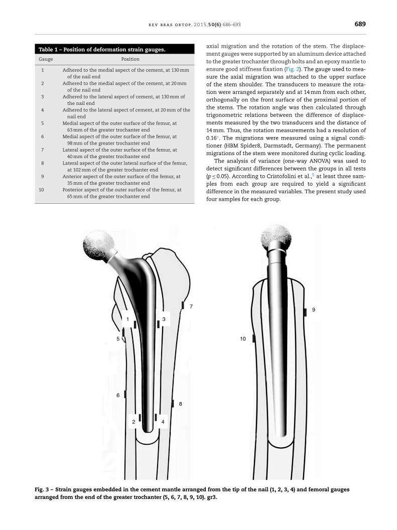
Strains on the outer surface of the femurs were measuredthrough six axial electrical resistance strain-gauges (KyowaKFG 2-120-C1-11-N15-C02, Tokyo, Japan) at the three testmoments. The strain gauges were attained to the femurs aswell as to the cement in a similar manner as described in aprevious protocol.7 The gauges were arranged in the direc-tion of the femoral axis. The positions of the gauges weremeasured by an altimeter (0.1 mm resolution). Strains in thecement mantle were measured by four axial electrical resis-tance strain-gauges during the static loads after implantation,and during the final static loads after the cyclic loads. Dur-ing cyclic loading, strains in the cement mantle were alsomonitored to evaluate permanent deformations. Bone cementlayers were applied in the proximal and distal levels of eachstem. Cement layers were sanded until a thickness of one mmwas achieved, measured with a caliper (0.1 mm resolution).The gauges were applied to the cement layer on the medial andlateral sides. Fig. 1 shows a strain gauge attached to the distalaspect of a stem, prior to implantation. Table 1 describes thepositions of all strain gauges used in this study. Fig. 3 shows thepositions of the strain gauges in relation to both the cementmantle and the femur. The deformations were measured witha signal conditioner (HBM MGCplus, Dannstadt, Germany). Toincrease data reliability all the strain gauges were calibratedusing a precision electrical resistor.
The axial and rotational migration of the stems in relationto the femurs were measured through a displacement gage(0.01 mm resolution) and two linear variable displacementtransducers (0.02 mm resolution) to evaluate, respectively the
r e v b r a s o r t o p . 2 0 1 5
Table 1 – Position of deformation strain gauges.
Gauge Position
1 Adhered to the medial aspect of the cement, at 130 mmof the nail end
2 Adhered to the medial aspect of the cement, at 20 mmof the nail end
3 Adhered to the lateral aspect of cement, at 130 mm ofthe nail end
4 Adhered to the lateral aspect of cement, at 20 mm of thenail end
5 Medial aspect of the outer surface of the femur, at63 mm of the greater trochanter end
6 Medial aspect of the outer surface of the femur, at98 mm of the greater trochanter end
7 Lateral aspect of the outer surface of the femur, at40 mm of the greater trochanter end
8 Lateral aspect of the outer lateral surface of the femur,at 102 mm of the greater trochanter end
9 Anterior aspect of the outer surface of the femur, at35 mm of the greater trochanter end
10 Posterior aspect of the outer surface of the femur, at65 mm of the greater trochanter end
3
7
1
5
6
8
42
Fig. 3 – Strain gauges embedded in the cement mantle arrangedarranged from the end of the greater trochanter (5, 6, 7, 8, 9, 10).
;5 0(6):686–693 689
axial migration and the rotation of the stem. The displace-ment gauges were supported by an aluminum device attachedto the greater trochanter through bolts and an epoxy mantle toensure good stiffness fixation (Fig. 2). The gauge used to mea-sure the axial migration was attached to the upper surfaceof the stem shoulder. The transducers to measure the rota-tion were arranged separately and at 14 mm from each other,orthogonally on the front surface of the proximal portion ofthe stems. The rotation angle was then calculated throughtrigonometric relations between the difference of displace-ments measured by the two transducers and the distance of14 mm. Thus, the rotation measurements had a resolution of0.16◦. The migrations were measured using a signal condi-tioner (HBM Spider8, Darmstadt, Germany). The permanentmigrations of the stem were monitored during cyclic loading.
The analysis of variance (one-way ANOVA) was used todetect significant differences between the groups in all tests(p ≤ 0.05). According to Cristofolini et al.,5 at least three sam-ples from each group are required to yield a significant
difference in the measured variables. The present study usedfour samples for each group.
10
9
from the tip of the nail (1, 2, 3, 4) and femoral gaugesgr3.
690 r e v b r a s o r t o p . 2 0 1 5;5 0(6):686–693
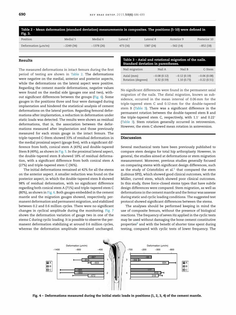
Table 2 – Mean deformation (standard deviation) measurements in composites. The positions (5-10) were defined inFig. 3.
Table 3 – Axial and rotational migration of the nails.Standard deviation in parentheses.
Nail migration Nail A Nail B C-Stem
Deformation (�m/m) −2249 (34) −1378 (26)
Results
The measured deformations in intact femurs during the firstperiod of testing are shown in Table 2. The deformationswere negative on the medial, anterior and posterior aspects,while the deformations on the lateral aspect were positive.Regarding the cement mantle deformations, negative valueswere found on the medial side (gauges one and two), with-out significant differences between the groups (Fig. 4). Somegauges in the positions three and four were damaged duringimplantation and hindered the statistical analysis of cementdeformations on the lateral portion. Regarding femoral defor-mations after implantation, a reduction in deformation understatic loads was detected. The results were shown as residualdeformations, that is, the association between the defor-mations measured after implantation and those previouslymeasured for each strain gauge in the intact femurs. Thetriple-tapered C-Stem showed 33% of residual deformation inthe medial proximal aspect (gauge five), with a significant dif-ference from both, conical stem A (43%) and double-taperedStem B (49%), as shown in Fig. 5. In the proximal lateral aspect,the double-tapered stem B showed 18% of residual deforma-tion, with a significant difference from both conical stem A(27%) and triple-tapered stem C (36%).
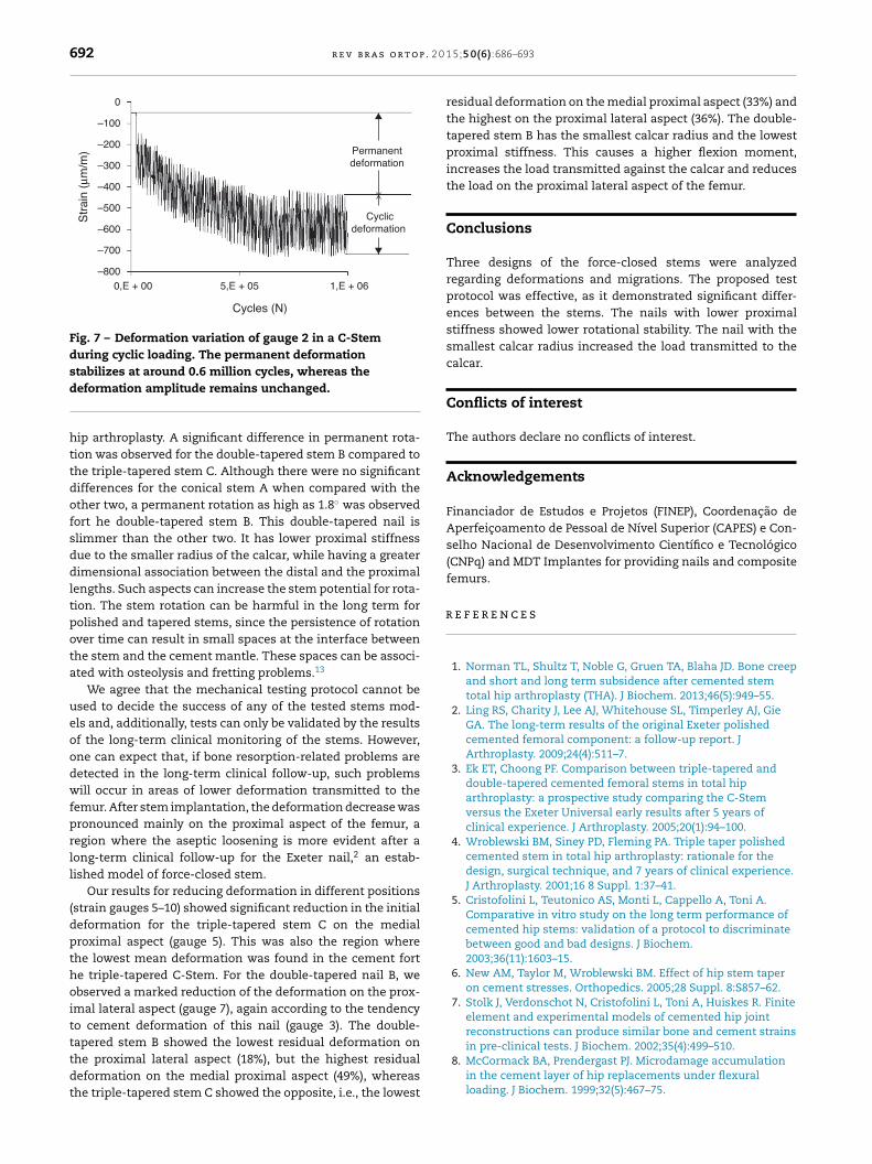
The initial deformations remained at 42% for all the stemson the anterior aspect. A smaller reduction was found on theposterior aspect, in which the double-tapered stem B showed98% of residual deformation, with no significant differenceregarding both conical stem A (71%) and triple-tapered stem C(80%), as shown in Fig. 6. Both gauges embedded in the cementmantle and the migration gauges showed, respectively, per-manent deformation and permanent migration, and stabilizedbetween 0.2 and 0.6 million cycles. There were no significantchanges in cyclical amplitude during the monitoring. Fig. 7
shows the deformation variation of gauge two in one of thestems C during cyclic loading. It is possible to observe the per-manent deformation stabilizing at around 0.6 million cycles,whereas the deformation amplitude remained unchanged.
A
–1400 –900 –400
–667–819
–603
–984–993
–6722
1
Deformation (µ m/m)
B
C
Fig. 4 – Deformations measured during the initial static
No significant differences were found in the permanent axialmigration of the nails. The distal migration, known as sub-sidence, occurred in the mean interval of 0.06 mm for thetriple-tapered stem C and 0.12 mm for the double-taperedstem B (Table 3). There was a significant difference in thepermanent rotation between the double-tapered stem B andthe triple-tapered stem C, respectively, with 1.1◦ and 0.22◦
(Table 3). Stem rotation generally occurred in retroversion.However, the stem C showed mean rotation in anteversion.
Discussion
Several mechanical tests have been previously published tocompare stem designs for total hip arthroplasty. However, ingeneral, the studies aimed at deformations or stem migrationmeasurement. Moreover, previous studies generally focusedon comparing stems with significant design differences, suchas the study of Cristofolini et al.5 that compared the stem(Lubinus SPII), which showed good clinical outcomes, with theMüller, curved stem, which showed poor clinical outcomes.In this study, three force-closed stems types that have subtledesign differences were compared. Stem migration, as well asdeformations in the cement mantle and the femur was assesseduring static and cyclic loading conditions. The suggested testprotocol showed significant differences between the stems.
The analyses should be performed keeping in mind theuse of composite femurs, without the presence of biologicalreactions. The frequency of seven Hz applied in the cyclic tests
may be used without damaging the bone cement constitutiveproperties8 and with the benefit of shorter time spent duringtesting, compared with cyclic tests of lower frequency. The
–700 –200 –300 –800
694–392
–68
177413
3184
3
Deformation (µm/m)
A
B
C
loads in positions (1, 2, 3, 4) of the cement mantle.
r e v b r a s o r t o p . 2 0 1 5;5 0(6):686–693 691
Medial Lateral
0.43
0.49
0.33
0.27
0.18
0.36
00.5
5
68
7
A
B
C
A
B
C
Residual deformation
Residual deformation
1
0.67
0.77
0.64
0.63
0.62
0.70
0
A
B
C
A
B
C
1 0.5
Residual deformation
10 0.5
10.5
Residual deformation
0
late
tAatsbgimtat
Fig. 5 – Residual deformations on the medial and
ests were performed without the presence of muscle forces.lthough a sudy9 showed the importance of muscle forcespplied to the greater trochanter for a better assessment ofhe distribution of stress due to total hip replacement, thistudy was effective in producing significant differences inoth migration and deformation. While some deformationauges in positions three and four were damaged duringmplantation and hindered the statistical analysis of cement
antle deformation only in the lateral region, we were able
o compare cement deformations in the medial region ofll stems. No significant differences were found betweenhe three stems with respect to cement deformation. The
Posterior
A
B
0.71
100.98
0.80
1.5 1
Residual deformation
0.5 0
C
Fig. 6 – Residual deformations on the anterior and posteri
ral aspects of implants under initial static loads.
permanent displacements and deformations measured inour cyclic tests showed a decreasing rate that stabilizedbetween 0.2 and 0.6 million cycles. The imposed load on thecement mantle during the in vivo postures results in the flowof cement. The flow rate decreases with time (or the cyclicloads), and although it remains for a long time, it may becomeinsignificant in the long-term.10 According to Nelissen et al.11
stabilizing the migration rate of a double-tapered stem occurswithin six months of in vivo use. Therefore, it is possible to
compare our cyclic loading with such a period of in vivo use.
According to Stolk et al.12 the rotation is the primary modeof migration in such concepts of force-closed stems for total
anterior
90.42
A
B
C
0.42
0.42
0 0.2
Residual deformation
0.4 0.6
or aspects of implants under initial static loads. GR6.
692 r e v b r a s o r t o p . 2 0
0
–8000,E + 00 5,E + 05 1,E + 06
Permanentdeformation
Cyclicdeformation
Str
ain
(µm
/m)
Cycles (N)
–700
–600
–500
–400
–300
–200
–100
Fig. 7 – Deformation variation of gauge 2 in a C-Stemduring cyclic loading. The permanent deformationstabilizes at around 0.6 million cycles, whereas the
r
deformation amplitude remains unchanged.
hip arthroplasty. A significant difference in permanent rota-tion was observed for the double-tapered stem B compared tothe triple-tapered stem C. Although there were no significantdifferences for the conical stem A when compared with theother two, a permanent rotation as high as 1.8◦ was observedfort he double-tapered stem B. This double-tapered nail isslimmer than the other two. It has lower proximal stiffnessdue to the smaller radius of the calcar, while having a greaterdimensional association between the distal and the proximallengths. Such aspects can increase the stem potential for rota-tion. The stem rotation can be harmful in the long term forpolished and tapered stems, since the persistence of rotationover time can result in small spaces at the interface betweenthe stem and the cement mantle. These spaces can be associ-ated with osteolysis and fretting problems.13
We agree that the mechanical testing protocol cannot beused to decide the success of any of the tested stems mod-els and, additionally, tests can only be validated by the resultsof the long-term clinical monitoring of the stems. However,one can expect that, if bone resorption-related problems aredetected in the long-term clinical follow-up, such problemswill occur in areas of lower deformation transmitted to thefemur. After stem implantation, the deformation decrease waspronounced mainly on the proximal aspect of the femur, aregion where the aseptic loosening is more evident after along-term clinical follow-up for the Exeter nail,2 an estab-lished model of force-closed stem.
Our results for reducing deformation in different positions(strain gauges 5–10) showed significant reduction in the initialdeformation for the triple-tapered stem C on the medialproximal aspect (gauge 5). This was also the region wherethe lowest mean deformation was found in the cement forthe triple-tapered C-Stem. For the double-tapered nail B, weobserved a marked reduction of the deformation on the prox-imal lateral aspect (gauge 7), again according to the tendencyto cement deformation of this nail (gauge 3). The double-
tapered stem B showed the lowest residual deformation onthe proximal lateral aspect (18%), but the highest residualdeformation on the medial proximal aspect (49%), whereasthe triple-tapered stem C showed the opposite, i.e., the lowest
1 5;5 0(6):686–693
residual deformation on the medial proximal aspect (33%) andthe highest on the proximal lateral aspect (36%). The double-tapered stem B has the smallest calcar radius and the lowestproximal stiffness. This causes a higher flexion moment,increases the load transmitted against the calcar and reducesthe load on the proximal lateral aspect of the femur.
Conclusions
Three designs of the force-closed stems were analyzedregarding deformations and migrations. The proposed testprotocol was effective, as it demonstrated significant differ-ences between the stems. The nails with lower proximalstiffness showed lower rotational stability. The nail with thesmallest calcar radius increased the load transmitted to thecalcar.
Conflicts of interest
The authors declare no conflicts of interest.
Acknowledgements
Financiador de Estudos e Projetos (FINEP), Coordenacão deAperfeicoamento de Pessoal de Nível Superior (CAPES) e Con-selho Nacional de Desenvolvimento Científico e Tecnológico(CNPq) and MDT Implantes for providing nails and compositefemurs.
e f e r e n c e s
1. Norman TL, Shultz T, Noble G, Gruen TA, Blaha JD. Bone creepand short and long term subsidence after cemented stemtotal hip arthroplasty (THA). J Biochem. 2013;46(5):949–55.
2. Ling RS, Charity J, Lee AJ, Whitehouse SL, Timperley AJ, GieGA. The long-term results of the original Exeter polishedcemented femoral component: a follow-up report. JArthroplasty. 2009;24(4):511–7.
3. Ek ET, Choong PF. Comparison between triple-tapered anddouble-tapered cemented femoral stems in total hiparthroplasty: a prospective study comparing the C-Stemversus the Exeter Universal early results after 5 years ofclinical experience. J Arthroplasty. 2005;20(1):94–100.
4. Wroblewski BM, Siney PD, Fleming PA. Triple taper polishedcemented stem in total hip arthroplasty: rationale for thedesign, surgical technique, and 7 years of clinical experience.J Arthroplasty. 2001;16 8 Suppl. 1:37–41.
5. Cristofolini L, Teutonico AS, Monti L, Cappello A, Toni A.Comparative in vitro study on the long term performance ofcemented hip stems: validation of a protocol to discriminatebetween good and bad designs. J Biochem.2003;36(11):1603–15.
6. New AM, Taylor M, Wroblewski BM. Effect of hip stem taperon cement stresses. Orthopedics. 2005;28 Suppl. 8:S857–62.
7. Stolk J, Verdonschot N, Cristofolini L, Toni A, Huiskes R. Finiteelement and experimental models of cemented hip jointreconstructions can produce similar bone and cement strains
in pre-clinical tests. J Biochem. 2002;35(4):499–510.
8. McCormack BA, Prendergast PJ. Microdamage accumulationin the cement layer of hip replacements under flexuralloading. J Biochem. 1999;32(5):467–75.
9. Van der Ploeg B, Tarala M, Homminga J, Janssen D, Buma P,Verdonschot N. Toward a more realistic prediction ofperi-prosthetic micromotions. J Orthop Res.2012;30(7):1147–54.
0. Stolk J, Verdonschot N, Murphy BP, Prendergast PJ, Huiskes R.Finite element simulation of anisotropic damage
accumulation and creep in acrylic bone cement. Eng FractMech. 2004;71(4–6):513–28.
1. Nelissen RG, Garling EH, Valstar ER. Influence of cementviscosity and cement mantle thickness on migration of the
1
;5 0(6):686–693 693
Exeter total hip prosthesis. J Arthroplasty. 2005;20(4):521–8.
2. Stolk J, Maher SA, Verdonschot N, Prendergast PJ, Huiskes R.Can finite element models detect clinically inferiorcemented hip implants? Clin Orthop Relat Res.2003;409:138–50.
3. Glyn-Jones S, Gill HS, Beard DJ, McLardy-Smith P, Murray DW.Influence of stem geometry on the stability of polishedtapered cemented femoral stems. J Bone Joint Surg Br.2005;87(7):921–7.