United States United Kingdom Germany France Nordic Italy Spain Japan U.S. Navy Approved Connectors and Accessories First Edition • September 2011 MIL-PRF-28876 QPL and MIL-DTL-28840 QPL
Transcript
U n i t e d S t a t e s U n i t e d K i n g d o m G e r m a n y F r a n c e N o r d i c I t a l y S p a i n J a p a n
U.S. Navy Approved Connectors and Accessories
F i r s t E d i t i o n • S e p t e m b e r 2 0 1 1
MIL-PRF-28876 QPL and MIL-DTL-28840 QPL
Glenair Rapid-Response Manufacturing and Same-Day Stocking
•• Connectors and Dust Covers Qualified to the Complete Requirements of MIL-PRF-28876 including Plugs, Wall-Mount Receptacles, Jam-Nut Mount Receptacles and In-Line Receptacles
•• Multiple Shell Sizes and Insert Arrangements, Including 2, 4, 6, 8, 18 and 31 Channel Layouts
•• Backshells in Straight, 45° and 90° Configurations
•• Corrosion-Resistant and Environmentally Sealed
•• Qualified MIL-PRF-29504/14 and /15 Pin and Socket Termini and /3 Dummy Terminus
•• Same-Day Availability
Qualified MIL-PRF-28876 Fiber Optic Connectors and MIL-PRF-29504 TerminiNavy Approved, In Stock, and Ready for Immediate Shipment
The use of fiber optics in shipboard and ship-to-shore data transmissions is growing rapidly, and the tight-tolerance MIL-PRF-28876 interconnect has become the universal standard for Navy shipboard applications. Glenair's qualified offering—including QPL’d MIL-PRF-29504/14 and /15 termini and the broad range of connectors, backshells, and dust cap accessories—delivers all the necessary performance from precise optical alignment to environmental protection and corrosion resistance. Glenair MIL-PRF-28876 QPL connectors and termini are ready for deployment in shipboard, surface and submarine applications, as well as mission-critical combat communication systems such as mobile tactical shelters. They are specifically geared for upgrade and retrofit applications where extending system life-cycles and reducing cost of ownership are principal requirements. For more information, or for product samples, please consult the factory or visit us at www.glenair.com.
www.glenair.com E-Mail: [email protected], INC. • 1211 AIR WAY • GLENDALE, CA 91201-2497 • 818-247-6000 • FAX 818-500-9912
Test Description Performance Requirements/Specifi cations
Optical Insertion Loss, Multimode -0.3 dB Typical (62.5/125)
Optical Insertion Loss, Singlemode -0.3 dB Typical (9/125)
Optical Back Refl ection, Singlemode Better than -40 dB - PC PolishBetter than -50 dB - Enhanced PC Polish
Operating Temperature -28°C to +65°C using MIL-Spec Qualifi ed Epoxy and Cable, or-55°C to +125°C using alternative Epoxy and Cable (consult factory)
Temperature (Thermal) Shock -40°C to +70°C, 5 Cycles, per TIA/EIA-455-71, Test Schedule C
Temperature Cycling -28°C to +65°C, 5 Cycles, per TIA/EIA-455-3
Temperature/Humidity Cycling -10°C to +65°C, 10 Cycles, 240 hours, 98% RH, per TIA/EIA-455-5, Test Method B
Temperature Life Aging +110°C, 240 hours, Dry Air, per TIA/EIA-455-4
Mating Durability 500 cycles, per TIA/EIA-455-21
Vibration - Sinusoidal 10 g Peak, 5-500 Hz, 12 Cycles (3 hours) per Axis at Ambient Temperature, per TIA/EIA-455-11, Test Condition II
Vibration - Random 10.2 g RMS, 50-2000 Hz, 30 minutes per Axis at Ambient Temperature,per TIA/EIA-455-11, Test Condition VII-C
Mechanical Shock (High Impact) Per MIL-S-901, Lightweight, Grade A, Class I (Hammer Shock)
Impact 8 Drops from 8 feet, per TIA/EIA-455-2, Test Method B
Crush Resistance 281 lbs, 7 Loading Cycles, per TIA/EIA-455-26
External Bending Moment 300 inch-lbs min for 1 minute
Cable Pull Out Force - Termini 22 lbs min for 1 minute, per TIA/EIA-455-6
Cable Pull Out Force - Connector 162 lbs min for 10 minutes, per TIA/EIA-455-6
Cable Seal Flexing 180° Flex, 200 Cycles, per TIA/EIA-455-1
Cable Twist 360°±180° Twist, 50 Cycles, 11 lbs min Tension, per TIA/EIA-455-36
Ozone Exposure 150 ppm for 2 hours at +70°C, per TIA/EIA-455-189
Fungus Resistance 28 days at +30°C, 95% RH, per TIA/EIA-455-56
Fluid Immersion Turbine Fuel, Isopropyl Alcohol, Hydraulic Fluid, Lubricating Oil, Coolant, Tap Water, and Seawater, 24 hour immersion duration, per TIA/EIA-455-12
Water Pressure Equivalent depth of 32 feet for 48 hours at +10°C to +35°C
Freezing Water 1 hour, per TIA/EIA-455-98, Test Method A, Procedure 1
Corrosion Resistance (Salt Spray) 500 hours at +35°C, per TIA/EIA-455-16, Test Condition I
Sand and Dust 12 hours, per TIA/EIA-455-35
Flammability 0.75 inch fl ame for 10 seconds mated, 1.50 inch fl ame for 60 seconds unmated,per EIA/ECA-364-81
* Performance Specifi cations/Requirements based on the use of MIL-PRF-24792 Epoxy and MIL-PRF-85045 Simplexand Breakout Shipboard Optical Fiber.
Glenair, Inc.
The mechanical, electrical and environmental performance of 1000 Hour Grey™ is truly outstanding, far surpassing that of other metal alloy/fluorocarbon polymer plating solutions:
Advanced Durability, Conductivity, and Lubricity Plus Outstanding Corrosion Resistance!
�� Salt spray 1000 Hrs. static, 500 hrs. dynamic�� Low shell-to-shell resistance�� -55°C to 175°C temp. Rating�� 336+ hrs. sulfur dioxide resistance�� Non-magnetic�� Cadmium free�� Low coefficient of friction
The MIL-PRF-28876 specification does not, as of yet, establish any next-generation cadmium-free conductive plating options. But the Glenair advanced Nickel PTFE formula 1000 Hour Grey™ plating process (available in all of our M28876 commercial equivalent 180-040 series parts) meets all key performance requirements including shell-to-shell conductivity and long-term salt spray durability. 1000 Hour Grey™ delivers outstanding performance in a broad range of land, sea, and air interconnect applications. The non-reflective, non-magnetic, gun-metal gray surface finish is an ideal choice for naval applications with severe corrosion protection and EMI/EMC requirements.
Cadmium Free RoHS-Compliant
Plating Process Breaks 1000 Hour Corrosion Protection Barrier!
1000 Hour Grey™The Advanced Formula Ni-PTFE Plating Process for EMC Navy Applications
1211 Air Way • Glendale, CA 91201-2497 • Tel: 818-247-6000 • Fax: 818-500-9912 • E-Mail: [email protected] • Rev. 04.12.16
B
www.glenair.com E-Mail: [email protected], INC. • 1211 AIR WAY • GLENDALE, CA 91201-2497 • 818-247-6000 • FAX 818-500-9912
Dimensions in Inches (millimeters) are subject to change without notice.
M29504/14
181-039Size 16 Fiber Optic Pin Terminus
For MIL-PRF-28876 Connectors
Size 16 M29504/14 Fiber Optic Pin Terminus for MIL-PRF-28876 Connectors
Table II: Tools and Accessories
Part Number
Description
265-008
Crimp SleeveØ2.4mm Max Jacket
(Mil-Spec Type)
182-012 Crimp Tool
182-013 Insertion Tool, Straight
182-014 Insertion Tool, 90°
182-015 Removal Tool
182-035 Hand Polishing Tool
M28876QPL
.900 (22.9)Max
Spring Washers
Ø .102 (2.6)Max Ø A
FerruleHole
Environmental Seal
Retaining Clip
Crimp Sleeve Ø .118 (3.0) Max
TerminusAssembly
.158 (4.0)Min
Ø 2.0mm Ferrule OD
Ferrule
Material and FinishFerrule: Zirconia CeramicTerminus Assembly: Stainless Steel/ PassivateRetaining Clip, Spring Washers: Spring AlloySeal: FluorosiliconeCrimp Sleeve: Brass Alloy/Nickel
Notes• Crimp sleeve is supplied with terminus assembly and may be ordered separately
(see Table II). For terminus less crimp sleeve, omit C from end of part number.• See Glenair GAP-036 for termination procedure and assembly tools.• Dummy terminus part number: 181-051 or M29504/3-4038.
Table I: Part Number
Mil-Spec Part Number
ØA (Microns) Fiber TypeFiber Size
Core/Cladding(Microns)
Commercial Part Number
M29504/14-4140C 125.0 Single Mode 9/125 181-039-1250C
Not listed in
Mil-Spec125.5 Single Mode 9/125 181-039-1255C
M29504/14-4141C 126.0 Single Mode 9/125 181-039-1260C
M29504/14-4131C 126.0 Multi Mode 50/125, 62.5/125 181-039-1260C
M29504/14-4132C 127.0 Multi Mode 50/125, 62.5/125 181-039-1270C
M29504/14-4135C 142.0 Multi Mode 100/140 181-039-1420C
Consult factory for additional sizes and QPL status.
J
www.glenair.com E-Mail:[email protected], INC. • 1211 AIR WAY • GLENDALE, CA 91201-2497 • 818-247-6000 • FAX 818-500-9912
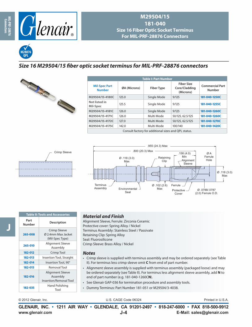
Size 16 M29504/15 fiber optic socket terminus for MIL-PRF-28876 connectors
Material and FinishAlignment Sleeve, Ferrule: Zirconia Ceramic Protective cover: Spring Alloy / Nickel Terminus Assembly: Stainless Steel / Passivate Retaining Clip: Spring Alloy Seal: Fluorosilicone Crimp Sleeve: Brass Alloy / Nickel
Notes• Crimp sleeve is supplied with terminus assembly and may be ordered separately (see Table
II). For terminus less crimp sleeve omit C from end of part number.• Alignment sleeve assembly is supplied with terminus assembly (packaged loose) and may
be ordered separately (see Table II). For terminus less alignment sleeve assembly, add N to end of part number (e.g. 181-040-1260CN).
• See Glenair GAP-036 for termination procedure and assembly tools. • Dummy Terminus: Part Number 181-051 or M29504/3-4038.
Protective Cover
.955 (24.3) Max
.800 (20.3) Max.158 (4.0)
MinAlignment
Sleeve
Ø AFerruleHole
Environmental Seal
Retaining Clip
Crimp Sleeve
TerminusAssembly
FerruleØ .0788/.0787
(2.0) Ferrule O.D.
Ø .118 (3.0) Max
Ø .102 (2.6) Max
Ø .118 (3.0)Max
Size 16 M29504/3 Fiber Optic Dummy Terminus for MIL-PRF-28876 Connectors
Table II: Tools and Accessories
Part Number Description
182-013 Insertion Tool, Straight
182-014 Insertion Tool, 90°
182-015 Removal Tool
Terminus Body
.557 (14.2) Max
Environmental Seal
Retaining Clip
Ø .102(2.6)
Ø .118 (.30)Max
Material and FinishTerminus Body: Stainless Steel/PassivateRetaining Clip: Spring Alloy/NickelSeal: Fluorosilicone
NotesSee Glenair GAP-036 for assembly tools and procedures.
B
www.glenair.com E-Mail: [email protected], INC. • 1211 AIR WAY • GLENDALE, CA 91201-2497 • 818-247-6000 • FAX 818-500-9912
Dimensions in Inches (millimeters) are subject to change without notice.
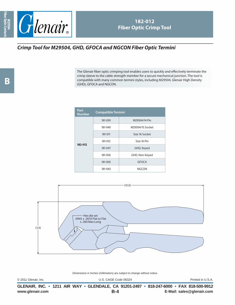
182-012
Fiber Optic Crimp Tool
The Glenair fi ber optic crimping tool enables users to quickly and eff ectively terminate the crimp sleeve to the cable strength member for a secure mechanical junction. The tool is compatible with many common termini styles, including M29504, Glenair High Density (GHD), GFOCA and NGCON.
Crimp Tool for M29504, GHD, GFOCA and NGCON Fiber Optic Termini
Part Number
Compatible Termini
182-012
181-039 M29504/14 Pin
181-040 M29504/15 Socket
181-011 Size 16 Socket
181-012 Size 16 Pin
181-047 GHD, Keyed
181-056 GHD, Non-Keyed
181-050 GFOCA
181-043 NGCON
Hex die set.0945 ± .0010 Flat to Flat
x .260 Max Long
(10.0)
(3.0)
B
www.glenair.com E-Mail: [email protected], INC. • 1211 AIR WAY • GLENDALE, CA 91201-2497 • 818-247-6000 • FAX 818-500-9912
Dimensions in Inches (millimeters) are subject to change without notice.
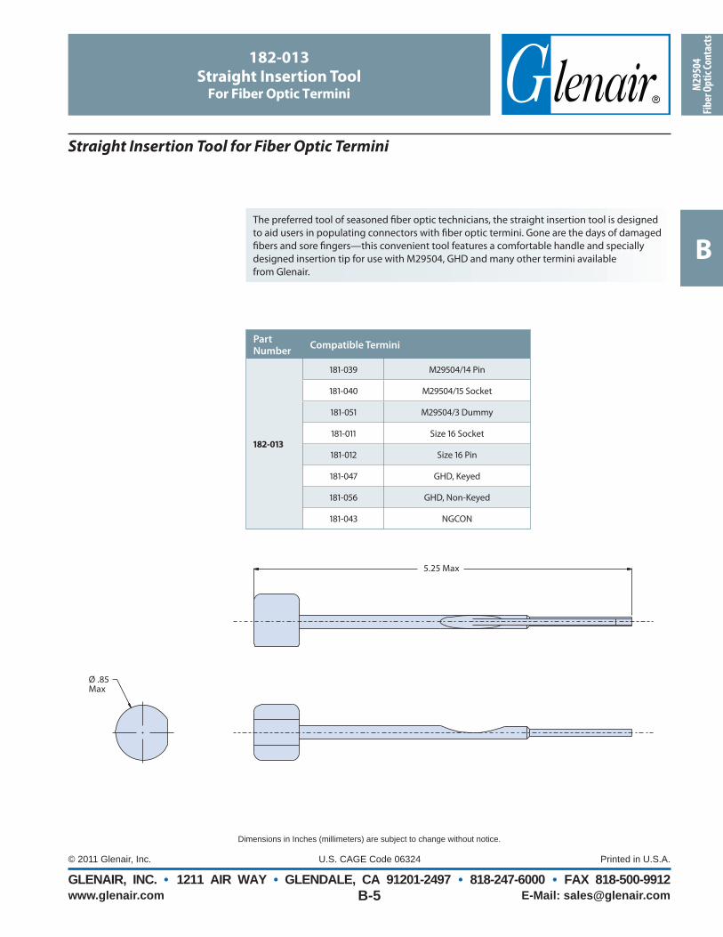
182-013
Straight Insertion ToolFor Fiber Optic Termini
The preferred tool of seasoned fi ber optic technicians, the straight insertion tool is designed to aid users in populating connectors with fi ber optic termini. Gone are the days of damaged fi bers and sore fi ngers—this convenient tool features a comfortable handle and specially designed insertion tip for use with M29504, GHD and many other termini availablefrom Glenair.
Straight Insertion Tool for Fiber Optic Termini
Part Number
Compatible Termini
182-013
181-039 M29504/14 Pin
181-040 M29504/15 Socket
181-051 M29504/3 Dummy
181-011 Size 16 Socket
181-012 Size 16 Pin
181-047 GHD, Keyed
181-056 GHD, Non-Keyed
181-043 NGCON
5.25 Max
Ø .85Max
B
www.glenair.com E-Mail: [email protected], INC. • 1211 AIR WAY • GLENDALE, CA 91201-2497 • 818-247-6000 • FAX 818-500-9912
Dimensions in Inches (millimeters) are subject to change without notice.
182-014
90° Insertion ToolFor Fiber Optic Termini
The 90° terminus insertion tool is designed to help populate connectors with fi ber termini in situations where space is limited—while off ering users the same easy insertion as with the straight 182-013 tool. Ideal for use in boxes and on connectors with backshells that inhibit normal rear insertion. Designed for use with M29504, GHD and many other termini available from Glenair.
Right Angle (90°) Insertion Tool for Fiber Optic Termini
Ø .20 Max
4.0 Max
1.0 Max
Part Number
Compatible Termini
182-014
181-039 M29504/14 Pin
181-040 M29504/15 Socket
181-051 M29504/3 Dummy
181-011 Size 16 Socket
181-012 Size 16 Pin
181-047 GHD, Keyed
181-056 GHD, Non-Keyed
181-043 NGCON
B
www.glenair.com E-Mail: [email protected], INC. • 1211 AIR WAY • GLENDALE, CA 91201-2497 • 818-247-6000 • FAX 818-500-9912
Dimensions in Inches (millimeters) are subject to change without notice.
182-015
Removal ToolFor Fiber Optic Termini
The fi ber optic terminus removal tool is designed for use with size 16 front release/rear entry termini. Sliding the tool into the face of the insulator and depressing the plunger—after fi rst removing the alignment sleeve from socket termini—enables users to quickly and easily remove the fi ber terminus from the rear of the insert. Compatible with Glenair front release fi ber optic termini.
Removal Tool for Fiber Optic Termini
4.50 Max.90 MaxTyp
1.00 MaxTyp
Part Number
Compatible Termini
182-015
181-039 M29504/14 Pin
181-040 M29504/15 Socket
181-051 M29504/3 Dummy
181-011 Size 16 Socket
181-012 Size 16 Pin
181-047 GHD, Keyed
181-056 GHD, Non-Keyed
181-043 NGCON
B
www.glenair.com E-Mail: [email protected], INC. • 1211 AIR WAY • GLENDALE, CA 91201-2497 • 818-247-6000 • FAX 818-500-9912
Dimensions in Inches (millimeters) are subject to change without notice.
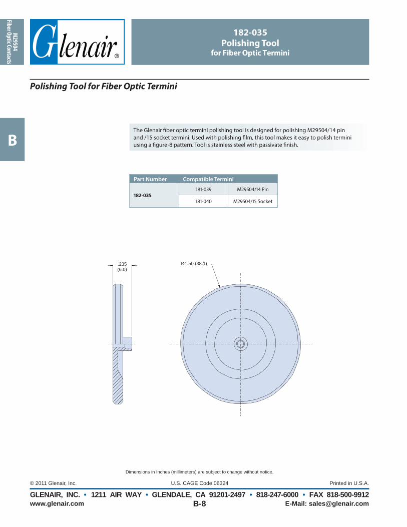
The Glenair fi ber optic termini polishing tool is designed for polishing M29504/14 pinand /15 socket termini. Used with polishing fi lm, this tool makes it easy to polish termini using a fi gure-8 pattern. Tool is stainless steel with passivate fi nish.
Polishing Tool for Fiber Optic Termini
Part Number Compatible Termini
182-035
181-039 M29504/14 Pin
181-040 M29504/15 Socket
.235 (6.0)
Ø1.50 (38.1)
182-035
Polishing Toolfor Fiber Optic Termini
B
www.glenair.com E-Mail: [email protected], INC. • 1211 AIR WAY • GLENDALE, CA 91201-2497 • 818-247-6000 • FAX 818-500-9912
Dimensions in Inches (millimeters) are subject to change without notice.
Reduce Size and Weight with Series 80 Mighty Mouse Fiber Optic ConnectorsNew size #16 fi ber optic termini can be used in any standard Mighty Mouse connector. Available for single mode or multi mode fi ber, these termini have low insertion loss and are intended for high-reliability aerospace applications. Series 80 connectors off er substantial reductions in size and weight compared to our D38999 type fi ber optic connectors.
Single Mode and Multi Mode
Snap-in, Rear Release
Precision Ceramic Ferrules
0.5 dB Typical Attenuation
1 to 22 ChannelsSeries 801 Plug with 181-057
pin terminus
The Series 801 9-4 receptacle is less than half the size of our D38999 type connector.
Series 801 receptacle with 181-075 socket terminus
Series 80 Mighty Mouse
Size #16 Fiber Optic Termini
Series 80 Contact Arrangements For Use With #16 Fiber Optic Termini
See Series 80 Mighty Mouse catalog for connector ordering information. Order connectors less contacts and order fi ber optic termini separately. Cavity numbers are mating face view of pin connectors.
Series 8016 Grams
(less contacts)
D38999 Series III27 Grams
(less contacts)
B
www.glenair.com E-Mail: [email protected], INC. • 1211 AIR WAY • GLENDALE, CA 91201-2497 • 818-247-6000 • FAX 818-500-9912
Dimensions in Inches (millimeters) are subject to change without notice.
181-057 Pin Terminus
181-057 Pin Terminus
181-075 Socket Terminus
181-075 Socket Terminus
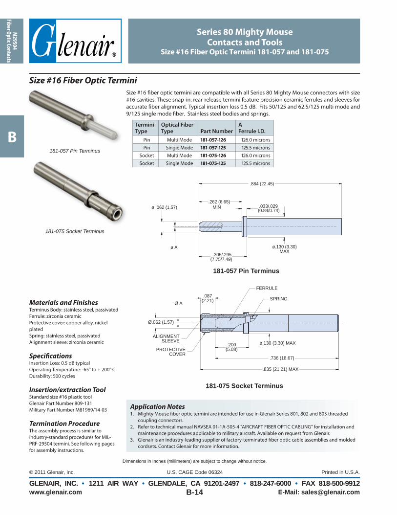
Size #16 fi ber optic termini are compatible with all Series 80 Mighty Mouse connectors with size #16 cavities. These snap-in, rear-release termini feature precision ceramic ferrules and sleeves for accurate fi ber alignment. Typical insertion loss 0.5 dB. Fits 50/125 and 62.5/125 multi mode and 9/125 single mode fi ber. Stainless steel bodies and springs.
Size #16 Fiber Optic Termini
Termini Type
Optical Fiber Type Part Number
AFerrule I.D.
Pin Multi Mode 181-057-126 126.0 micronsPin Single Mode 181-057-125 125.5 microns
Socket Multi Mode 181-075-126 126.0 micronsSocket Single Mode 181-075-125 125.5 microns
Application Notes1. Mighty Mouse fi ber optic termini are intended for use in Glenair Series 801, 802 and 805 threaded
coupling connectors. 2. Refer to technical manual NAVSEA 01-1A-505-4 "AIRCRAFT FIBER OPTIC CABLING" for installation and
maintenance procedures applicable to military aircraft. Available on request from Glenair. 3. Glenair is an industry-leading supplier of factory-terminated fi ber optic cable assemblies and molded
Specifi cationsInsertion Loss: 0.5 dB typicalOperating Temperature: -65° to + 200° CDurability: 500 cycles
Insertion/extraction ToolStandard size #16 plastic toolGlenair Part Number 809-131Military Part Number M81969/14-03
Termination ProcedureThe assembly process is similar to industry-standard procedures for MIL-PRF-29504 termini. See following pages for assembly instructions.
Series 80 Mighty Mouse
Contacts and ToolsSize #16 Fiber Optic Termini 181-057 and 181-075
181-057 Pin Terminus
p
i us
.087(2.21)
FERRULE
SPRING
Ø.062 (1.57)
ALIGNMENTSLEEVE
PROTECTIVECOVER
.835 (21.21) MAX
.736 (18.67)
ø.130 (3.30) MAX.200(5.08)
Ø A
ø.130 (3.30) MAX
MIN
.884 (22.45)
.262 (6.65)ø .062 (1.57) .033/.029
(0.84/0.74)
.305/.295(7.75/7.49)
ø A
B
www.glenair.com E-Mail: [email protected], INC. • 1211 AIR WAY • GLENDALE, CA 91201-2497 • 818-247-6000 • FAX 818-500-9912
Dimensions in Inches (millimeters) are subject to change without notice.
This assembly instruction lists two epoxies: A standard temperature epoxy and a high temperature epoxy. Ensure that the epoxy curing temperature is compatible with the temperature rating of the cable.
Recommended Epoxy Fiber Type Epoxy Curing Schedule
M24792A or equivalent AngstromBond® AB-9112 (Fiber Optic Center, Inc)
TRA-BOND™ F112 (Henkel)Standard
1 Hour @ 650C or 24 Hour Air Cure
EPO-TEK® 353ND (Epoxy Technology, Inc.)
Standard 2 Hours @ 800C
High temperature
Stage 1: 30 min. @ 800CStage 2: 30 min. @ 1000CStage 3: 10 min. @ 1500C
Series 80 Mighty Mouse
Contacts and ToolsSize #16 Fiber Optic Termini Assembly Procedure
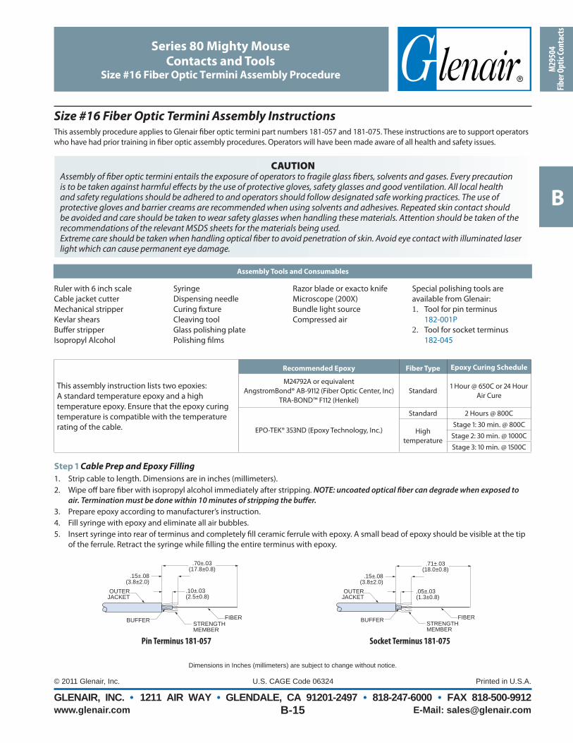
This assembly procedure applies to Glenair fi ber optic termini part numbers 181-057 and 181-075. These instructions are to support operators who have had prior training in fi ber optic assembly procedures. Operators will have been made aware of all health and safety issues.
CAUTIONAssembly of fi ber optic termini entails the exposure of operators to fragile glass fi bers, solvents and gases. Every precaution is to be taken against harmful eff ects by the use of protective gloves, safety glasses and good ventilation. All local health and safety regulations should be adhered to and operators should follow designated safe working practices. The use of protective gloves and barrier creams are recommended when using solvents and adhesives. Repeated skin contact should be avoided and care should be taken to wear safety glasses when handling these materials. Attention should be taken of the recommendations of the relevant MSDS sheets for the materials being used.Extreme care should be taken when handling optical fi ber to avoid penetration of skin. Avoid eye contact with illuminated laser light which can cause permanent eye damage.
Assembly Tools and Consumables
Ruler with 6 inch scaleCable jacket cutterMechanical stripperKevlar shearsBuff er stripperIsopropyl Alcohol
SyringeDispensing needleCuring fi xtureCleaving toolGlass polishing platePolishing fi lms
Razor blade or exacto knifeMicroscope (200X)Bundle light sourceCompressed air
Special polishing tools are available from Glenair:1. Tool for pin terminus
182-001P2. Tool for socket terminus
182-045
Size #16 Fiber Optic Termini Assembly Instructions
Step 1 Cable Prep and Epoxy Filling
1. Strip cable to length. Dimensions are in inches (millimeters).2. Wipe off bare fi ber with isopropyl alcohol immediately after stripping. NOTE: uncoated optical fi ber can degrade when exposed to
air. Termination must be done within 10 minutes of stripping the buff er.3. Prepare epoxy according to manufacturer’s instruction.4. Fill syringe with epoxy and eliminate all air bubbles.5. Insert syringe into rear of terminus and completely fi ll ceramic ferrule with epoxy. A small bead of epoxy should be visible at the tip
of the ferrule. Retract the syringe while fi lling the entire terminus with epoxy.
.70±.03(17.8±0.8)
.15±.08(3.8±2.0)
.10±.03(2.5±0.8)
FIBERBUFFER STRENGTH MEMBER
OUTER JACKET
.71±.03(18.0±0.8)
.15±.08(3.8±2.0)
.05±.03(1.3±0.8)
FIBERBUFFER STRENGTH MEMBER
OUTER JACKET
Pin Terminus 181-057 Socket Terminus 181-075
B
www.glenair.com E-Mail: [email protected], INC. • 1211 AIR WAY • GLENDALE, CA 91201-2497 • 818-247-6000 • FAX 818-500-9912
Contacts and ToolsSize #16 Fiber Optic Termini Assembly Procedure
Polishing Steps for Domed PC Polish
Polish Step Paper Grit Size # of Figure 8's
Hand
Pressure Polishing Surface Lubricant
1st Polish 3 micron Silicon Carbide 15-20 Light 90 Durometer Pad Dry2nd Polish 3 micron Diamond 10 Light 90 Durometer Pad Distilled Water3rd Polish 1 micron Diamond 10 Light 90 Durometer Pad Distilled Water4th Polish 0.5 micron Diamond 5 Light 90 Durometer Pad Distilled Water5th Polish Ultra Fine 3 Light 90 Durometer Pad Distilled Water
Dimensions in Inches (millimeters) are subject to change without notice.
Step 2 Fiber Insertion
1. Fold back strength members and distribute evenlyover outer jacket of cable.
2. Carefully insert stripped fi ber into terminus until the cable jacket bottoms inside the terminus body.
3. Wipe off any excess epoxy that may emerge from the rear of the terminus upon insertion of the cable.
4. Bare fi ber should protrude approximately .15 inches (3.8mm) from the front of the terminus.
5. Be sure that the exterior surfaces of terminus are free of epoxy.
Step 3 Epoxy Curing
6. Using curing oven, carefully position terminated fi ber into a cavity of curing block. NOTE care must be taken to avoid breaking the protruding fi ber.
7. See “Recommended Epoxies and Curing Schedules” (previous page) for cure times.
Step 4 Scribe and Remove Excess Fiber
8. Hold terminus with fi ber pointing straight up and lightly score fi ber approximately .01 inch (0.3mm) above the ceramic ferrule.
9. Using fi ber cleaving tool, gently move the blade across fi ber to scribe glass. Do not use a sawing motion.
10. Grasp fi ber and pull gently upward until fi ber breaks.11. Carefully discard piece of fi ber.
Step 5 Polishing Procedure
12. Clean polishing fi lm, tool, and tip of terminus using distilled water after each step.
13. Dry all parts using lint-free wipes or compressed air.14. Wipe distilled water onto back of polishing fi lm and place
onto rubber pad.
15. Insert terminus into polishing tool. Polish terminus in small fi gure 8 motions using the following procedures.
16. Visually inspect terminus tip using microscope to prevent overpolishing after each polishing step.
17. Use light pressure through each polishing step.
Step 6 Workmanship Inspection
After completing fi nal polishing step, core area must be free of epoxy, scratches, pits and cracks. NOTE do not backlight fi ber when inspecting for scratches.
Step 7 Install Alignment Sleeve on Socket Terminus
Carefully slide alignment sleeve onto terminus ferrule until seated.
Step 8 Install Protective Sleeve on Socket Terminus
Push on protective metal sleeve until you feel it snap into place.
Step 9 Clean and Install Dust Cap on Socket Terminus
Clean end of terminus and install dust cap over protective cover.
.15 (3.8)STRENGTH
MEMBEROUTER
JACKET
EPOXY
.15 (3.8)
STRENGTH MEMBER OUTER
JACKET
EPOXY
Pin Terminus 181-057
Socket Terminus 181-075
Acceptable UnacceptableCLADDING
SMALLSCRATCHESCORE
ALIGNMENTSLEEVE
PROTECTIVE COVER
187-029 DUST CAP 181-075 SOCKET TERMINUS
B
www.glenair.com E-Mail: [email protected], INC. • 1211 AIR WAY • GLENDALE, CA 91201-2497 • 818-247-6000 • FAX 818-500-9912
Dimensions in Inches (millimeters) are subject to change without notice.
Dry Action Cleaning Toolfor Fiber Optic Termini
The Glenair Dry Action Cleaning Tool is an easy-to-handle fi ber optic terminus cleaning device, highly eff ective at removing oil and dust contamination from pin and socket termini—either inside or outside connector shells. Traditional wet-swab cleaning methods add drying time and can even introduce new contaminants to the polished terminus end-face. The Dry Action Cleaning Tool’s novel dry cleaning strand gently sweeps and lifts away dust and residue from the terminus end-face without the problems associated with wet swab methods. The tool features a convenient single-unit confi guration and an extendable tip for easy access to installed fi ber optic termini—saving time and avoiding potential additional contamination. Choose part number GCLT-H200 for MIL-PRF-28876 connectors.
Dry Action Cleaning Tool—The Fast Fiber Optic End Face Cleaner
Glenair Part number Used on
GCLT-H200 2.0MM MIL-PRF-28876
GCLT-HC250 GFOCA (MIL-DTL-83526)
GCLT-H160 MIL-DTL-38999
GCLT-H125 Glenair High Density (GHD), LUXCIS
GCLT-C125 LC, MU
GCLT-C250 SC, ST, FC
GCLT-MPO MTP, MPO, MT (FEMALE AND MALE)
GCLT-MTC MT MALE
GCLT-MTC-RE MT MALE refi ll cartridge
Eff ectively Removes:• Arizona Road Dust (ISO 12103-1)• Skin Oil Residue• Salt Water Residue• Alcohol Residue• Vegetable Residue• Hand Lotion• Distilled Water Residue• Graphite• T-Shirt Lint
Features and Benefi ts• Simple pushing motion to engage tool• Audible CLICK to alert the operator when tool is
fully engaged• Repeatable process that eliminates operator error• No experience required• Over 525+ cleanings per unit• Dry cleaning strand eliminates the need for solvents • Crush resistant to over 250N• Impact resistant to survive drops over 1.5m
GCLT-H200
www.glenair.comGLENAIR, INC. • 1211 Air Way • Glendale, CA 91201-2497 • Tel: 818-247-6000 • Email: [email protected] • www.glenair.com
The tight-tolerance MIL-PRF-28876 interconnect has become the universal standard for Navy shipboard applications. Glenair’s qualifi ed connectors deliver all the necessary performance, from precise optical alignment to environmental protection and corrosion resistance. Glenair MIL-PRF-28876 QPL connectors are ready for
deployment in shipboard, surface and submarine applications, as well as mission-critical combat communication systems such as mobile tactical shelters. They are specifi cally geared for upgrade and retrofi t applications where extending system life-cycles and reducing cost of ownership are principal requirements. For more information, or for product samples, please consult the factory or visit us at www.glenair.com.
FIBER OPTICFIBER OPTICC O N N E C T O R S A N D A C C E S S O R I E S
MIL-PRF-28876
C
www.glenair.com E-Mail: [email protected], INC. • 1211 AIR WAY • GLENDALE, CA 91201-2497 • 818-247-6000 • FAX 818-500-9912
C-1
Dimensions in Inches (millimeters) are subject to change without notice.
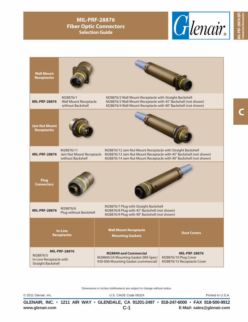
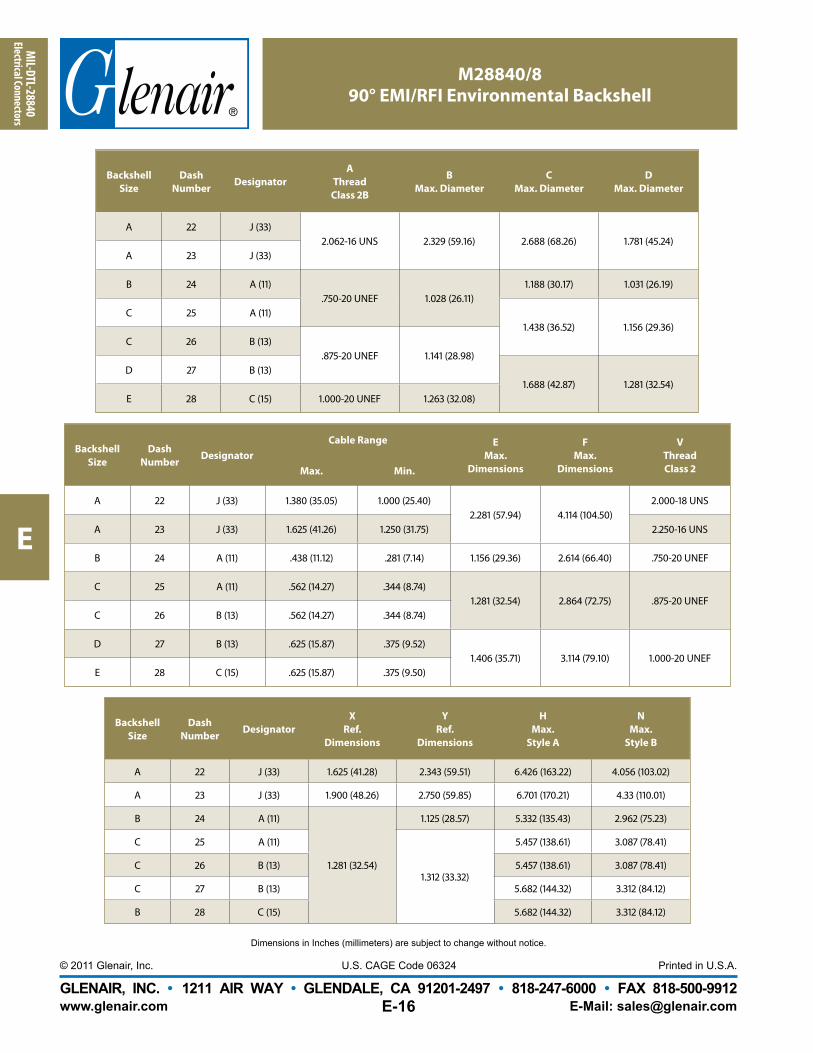
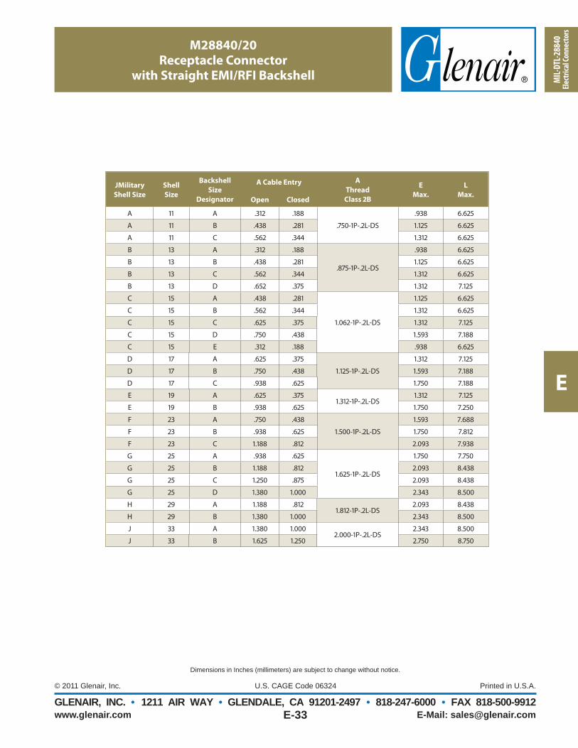
MIL-PRF-28876M28876/1Wall Mount Receptacle without Backshell
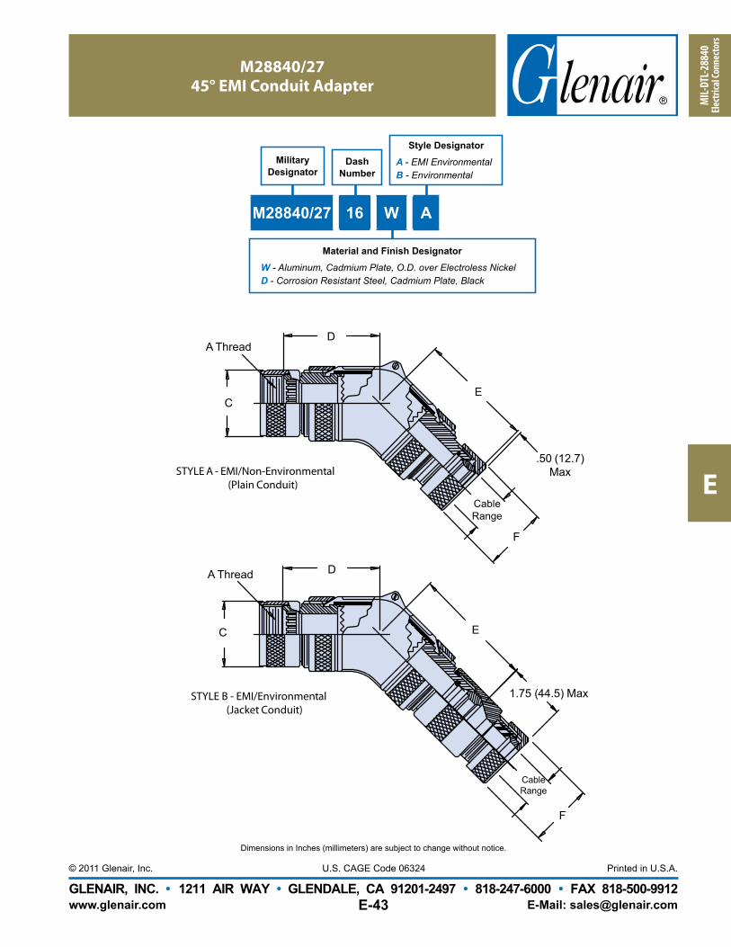
M28876/2 Wall Mount Receptacle with Straight BackshellM28876/3 Wall Mount Receptacle with 45° Backshell (not shown)M28876/4 Wall Mount Receptacle with 90° Backshell (not shown)
Jam Nut Mount Receptacles
MIL-PRF-28876M28876/11Jam Nut Mount Receptacle without Backshell
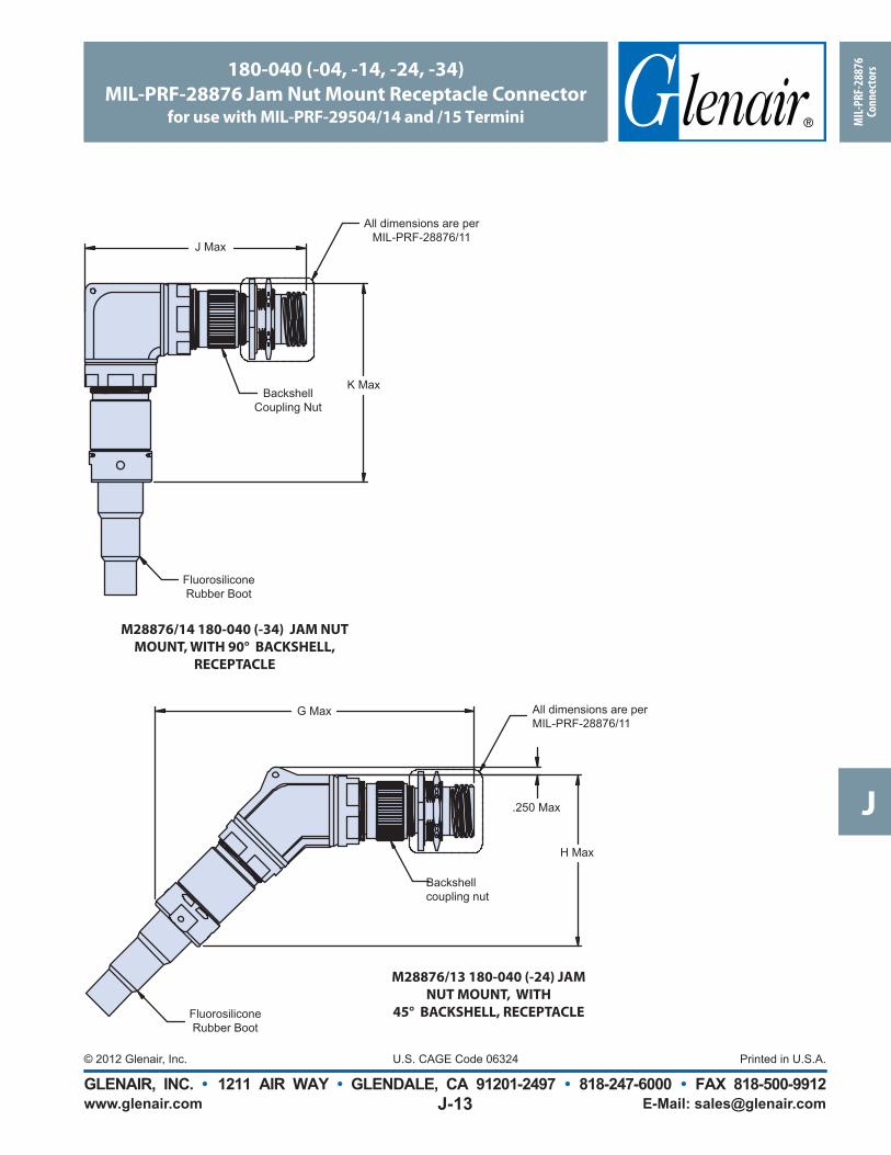
M28876/12 Jam Nut Mount Receptacle with Straight BackshellM28876/13 Jam Nut Mount Receptacle with 45° Backshell (not shown)M28876/14 Jam Nut Mount Receptacle with 90° Backshell (not shown)
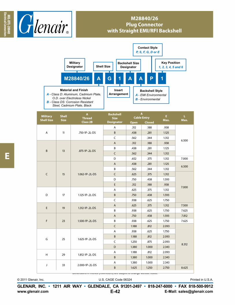
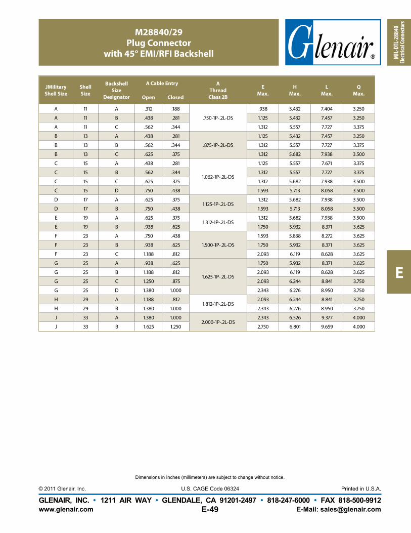
Plug Connectors
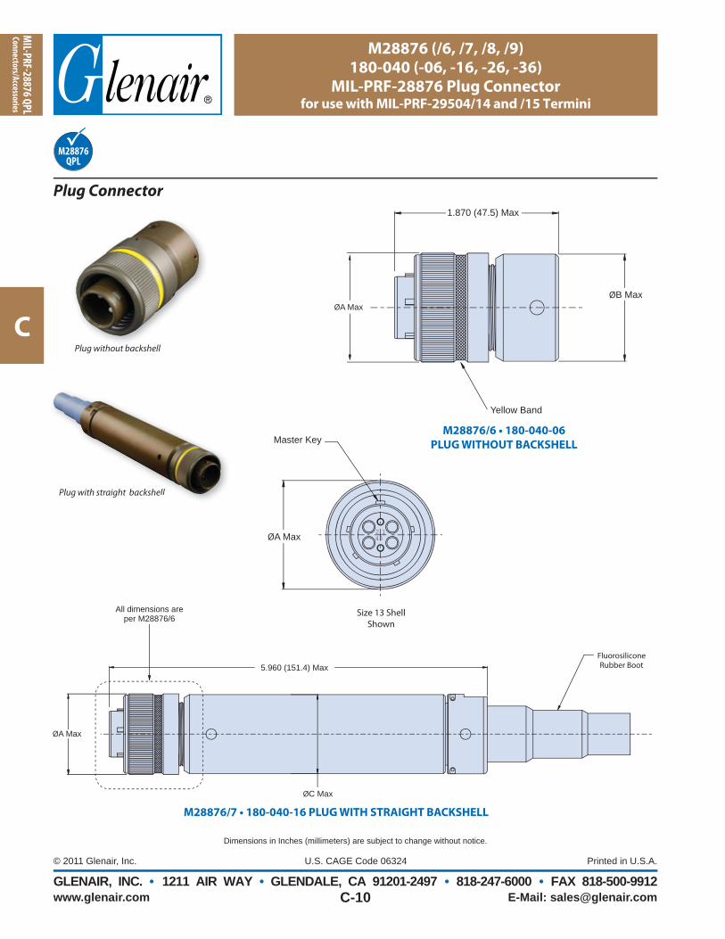
MIL-PRF-28876M28876/6Plug without Backshell
M28876/7 Plug with Straight BackshellM28876/8 Plug with 45° Backshell (not shown)M28876/9 Plug with 90° Backshell (not shown)
In-LineReceptacles
Wall Mount Receptacle
Mounting GasketsDust Covers
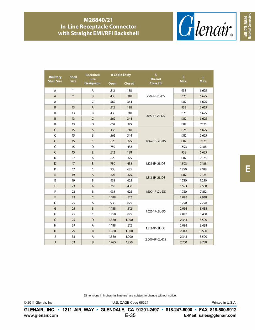
MIL-PRF-28876M28876/5In-Line Receptacle with Straight Backshell
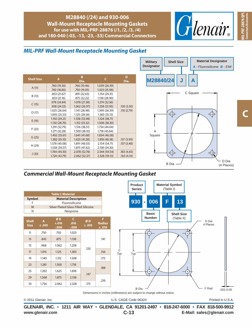
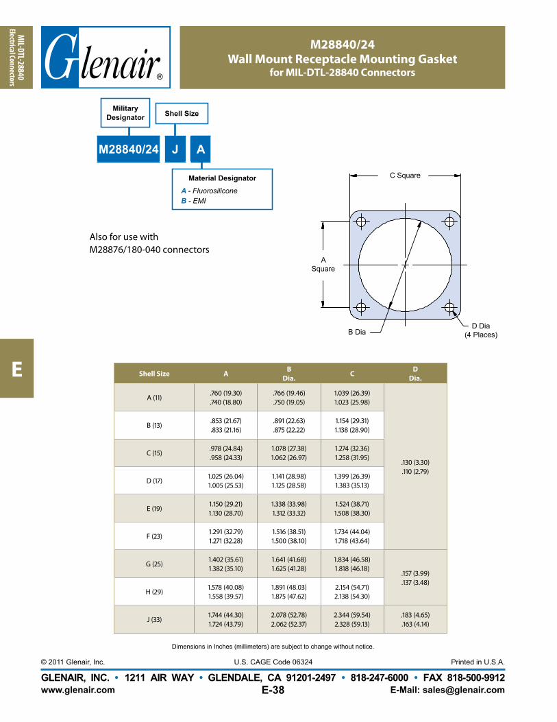
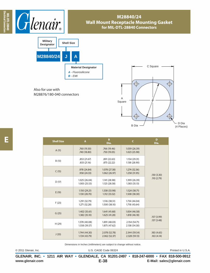
M28840 and CommercialM28840/24 Mounting Gasket (Mil-Spec)930-006 Mounting Gasket (commercial)
Dimensions in Inches (millimeters) are subject to change without notice.
MIL-PRF-28876 QPL Fiber Optic Connectors
M28876/1 through /14
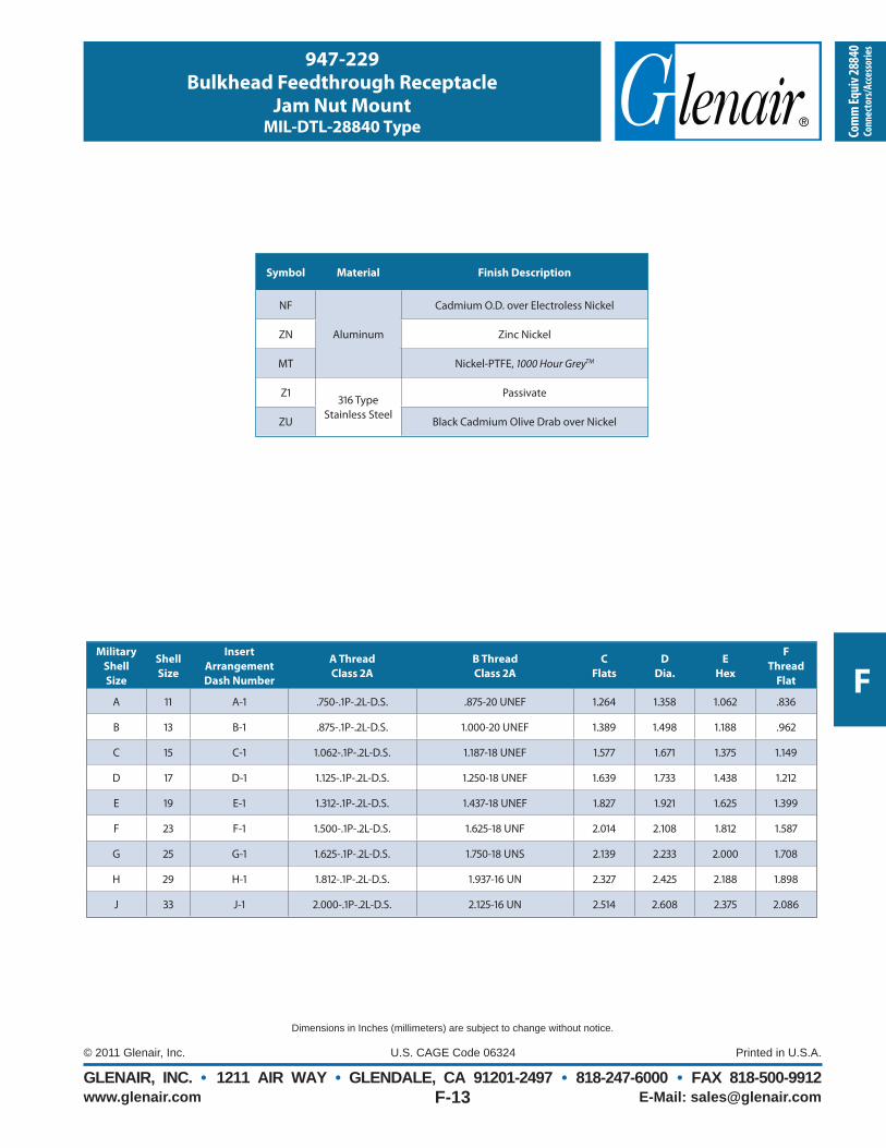
180-040 How to Order
Table I: Shell Finish
Sym Material Finish
NFAluminum
Alloy
Cadmium Plate, Olive Drab
(1000 Hrs. Salt Spray)
Material and FinishA. M28876 part numbers supplied standard with Cad plate/olive drab over aluminum alloy. See Table I for commercial plating options.B. Hardware: Aluminum alloy/chem fi lm, stainless steel/passivateC. Insert: Aluminum alloy/anodizeD. Seals: Fluorosilicone
Specifi cationsBacknut retained using thread-locking compound.Operating Temperature Range: -55° to +125°C.
A Chain (Sash) with Fastener (Eyelet) AttachmentB Chain (Sash) with Ring AttachmentC Wire Rope with Fastener (Eyelet) AttachmentD Wire Rope with Ring AttachmentE Without Chain (Sash) or Wire Rope
Table V: Lanyard Type (Commercial)Symbol Type
H Wire Rope, CoatedS Chain (Sash), PassivatedN No Lanyard
Consult Factory for Additional Options
Table II: Material and Finish (Commercial)
Code Material Finish Description
M
Aluminum Alloy
Electroless Nickel
NFCadmium, Olive Drab
MTNickel-PTFE,
GreyZR Zinc-Nickel, Black
Consult Factory for Additional Options
*MT plating available only with Glenair commercial equivalent part numbers
MaterialsandFinishNote: All M28876 Part Numbers are supplied
standard with Cadmium Plate, Olive Drab (1000 Hrs. Salt
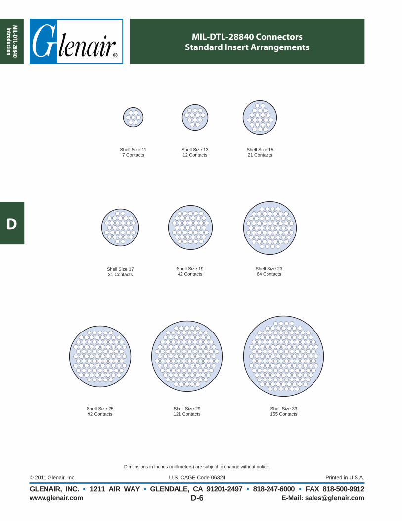
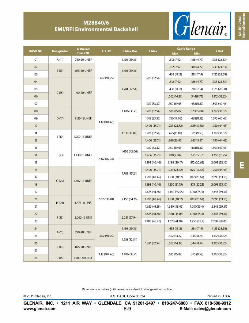
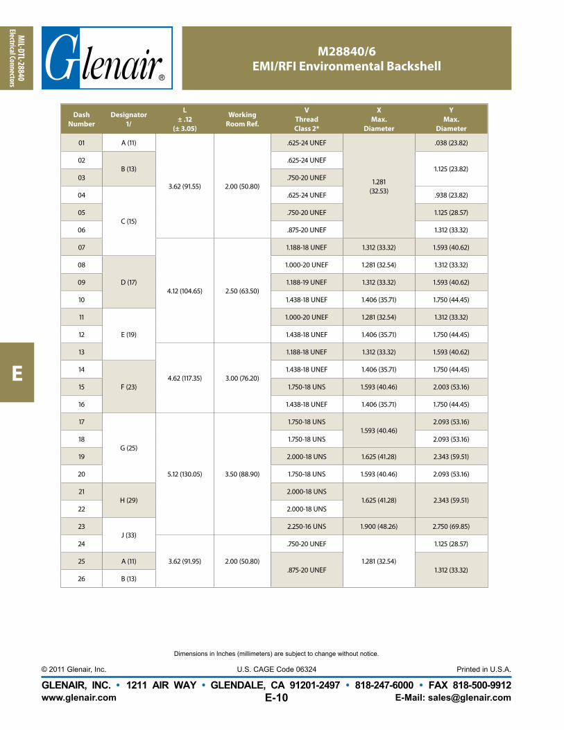
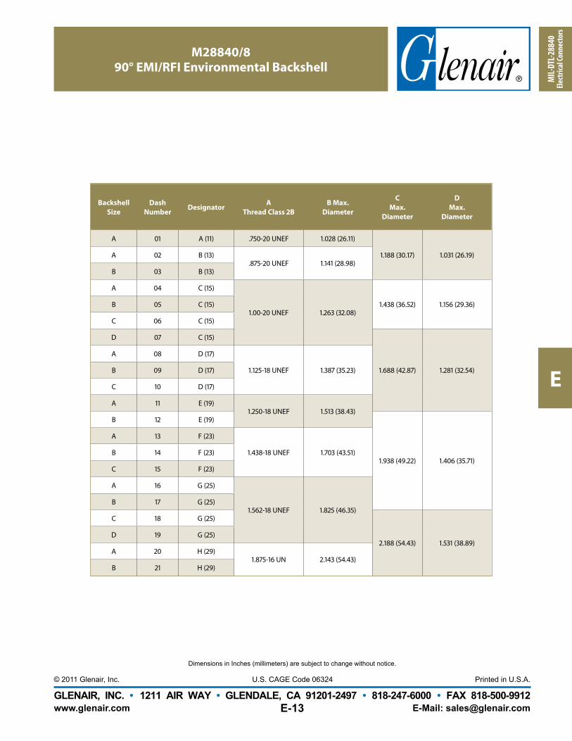
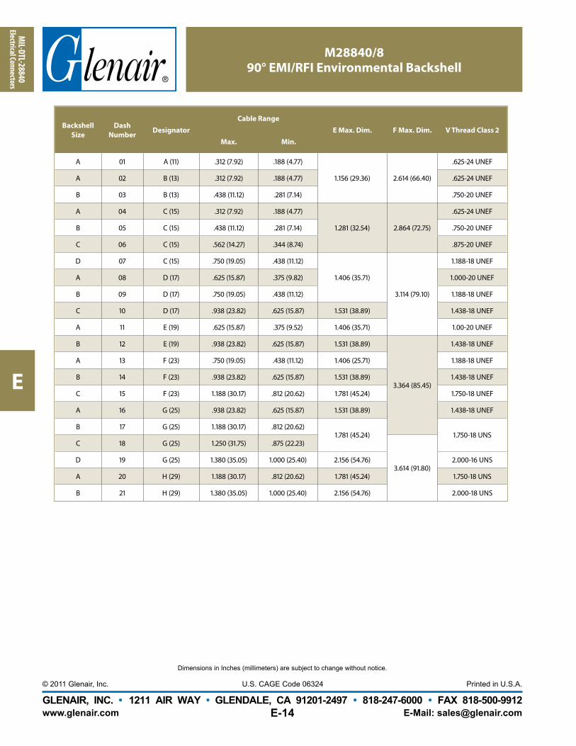
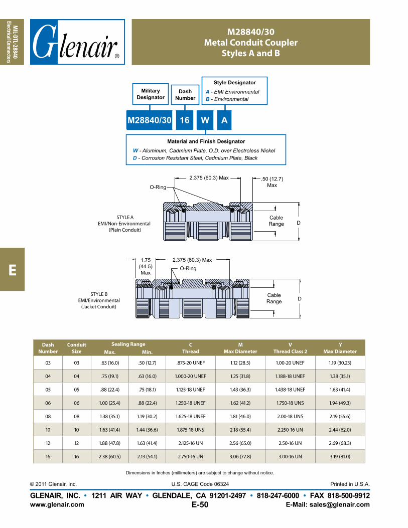
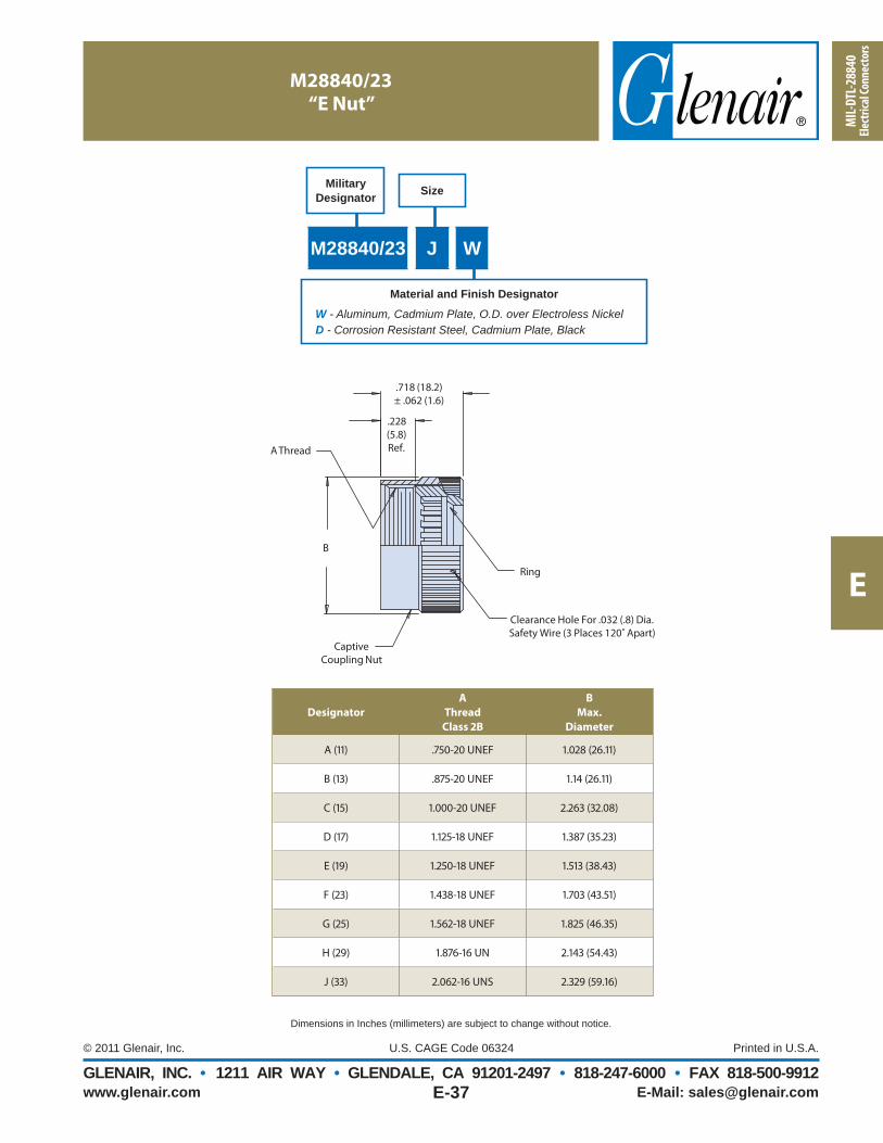
MIL-DTL-28840 Military Shipboard ConnectorsIntroduction
MIL-DTL-28840 In a Nutshell:MIL-DTL-28840 connectors were developed for the Navy for use in shipboard applications. They are a high density, environmental, circular connector series utilizing a high shock, threaded coupling system with front release crimped contacts. Note the splined backshell interface and the integrated wire sealing grommet that both add to the environmental and mechanical performance of this ruggedized connector.
Qualifi ed Military Standard Electrical Connectors and Accessories for Shipboard Applications
Ideal for All Rugged Environmental Applications
The standard connector and backshell series for shipboard use, MIL-DTL-28840 off ers high-density insert arrangement and high-shock performance. Glenair’s qualifi ed product line is fully tooled and highly available.
The MIL-DTL-28840 features RFI/EMI shielding, scoop-proof shells and corrosion resistant materials and fi nishes. In addition to all the connector types and styles, Glenair makes all the backshell accessory slash numbers as well.The addition of the MIL-DTL-28840 connector product line is part of Glenair’s total commitment to meeting all your shipboard interconnect requirements. So, if a rugged, environmental M28840 solution is in your future, think Glenair—from connectors to accessories.
ll h
PRODUCT FEATURES
• High Density, Scoop Proof Insert
Arrangements
• Flange Mount, Box Mount, Jam-Nut and
In-Line Receptacles
• Straight, 45° and 90° Strain Reliefs and
Backshell Assemblies
• Sav-Con® Connector Savers
• MIL-DTL-28840 Qualifi ed
• Additional Glenair Commercial Part Numbers
with Features Not Available in the Mil-Spec
the necctor.
MIL-D
TL-28840Introduction
D
www.glenair.com E-Mail: [email protected], INC. • 1211 AIR WAY • GLENDALE, CA 91201-2497 • 818-247-6000 • FAX 818-500-9912
D-2
Dimensions in Inches (millimeters) are subject to change without notice.
Shells, Coupling Nuts, Jam Nuts Aluminum alloy per ASTM B211, or stainless steel per AMS-QQ-S-763
ContactsCopper alloy, 50 μInch gold plated per ASTM B488 Type 3, Code C, Class 1,27 over nickel underplate per QQ-N-290 Class 2. Socket contact hood: stainless steel, passivated.
Insulators High Grade Engineering Plastic per ASTM D5948
Contact Retention Clip Beryllium copper
Shells, Coupling Nuts,Jam Nut Plating Finish
Stainless Steel, Black Cadmium plated
Grommet, Seal Blended elastomer, 30% silicone per ZZ-R-765, 70% fl uorosilicone per MIL-R-25988
Contact Code
Type Contact Spec.Contact
SizeAcceptable
Wire Size
Outside Diameter of Finished Wire
Minimum Maximum
F Pin SAE-AS39029/83-50820-20
242220
.040(1.02)
.070(1.78)
G Socket SAE-AS39029/84-509
P Pin SAE-AS39029/83-45020-22
262422S Socket SAE-AS39029/84-452
D Pin SAE-AS39029/83-45120-28
323028E Socket SAE-AS39029/84-453
NotesTo achieve sealing, wires must be built up to fi nished wire diameter.In accordance with MIL-DTL-24643 and MIL-DTL-16878.
MIL
-DTL
-288
40In
trod
ucti
on
D
www.glenair.com E-Mail: [email protected], INC. • 1211 AIR WAY • GLENDALE, CA 91201-2497 • 818-247-6000 • FAX 818-500-9912
D-3
Dimensions in Inches (millimeters) are subject to change without notice.
M81969/33-01, M81969/33-02, and M81969/34-01Contact Crimping, Insertion and Removal Tools
for MIL-DTL-28840 Connectors
M22520/34-02
PositionerThis bayonet-type positioner locates and holds contacts at the correct position for crimping with the M22520/34-01 Basic Crimp Tool. The face plate shows the correct tool settings.
ool. The
r
T
r
l Th
M22520/35 GagePeriodic Gaging is recommended to ensure accurate calibration, and is easily accomplished by setting the tool selector knob to the proper position and checking the indenter closure with the M22520/35 “Go/No-Go” Gage. Color coded anodized aluminum with stainless steel probes.
M22520/34-01 Basic Crimp ToolQualifi ed to M22520/34-01, this crimp tool prevents improper crimps and overcrimping and is based on the AFM8 miniature adjustable crimp tool. It performs a modifi ed eight impression crimp with a precision cycle controlled ratcheting mechanism for gas-tight wire terminations and excellent tensile strength. Also featured is a four-step crimp-depth selector knob, and is designed for use with the M22520/34-02 bayonet-type Positioner. Gaging is accomplished with the M22520/35 “go/No-Go” Gage. The adjustment wheel has eight settings. Check calibration with the M22520/35 gage. Length is 6.75 inches, weight is approximately 10 oz.
M81969/33-01 Straight Insertion ToolThe M81969/33-01 Straight Insertion Tool is approved for use on MIL-DTL-28840 connectors and features an anodized aluminum handle and stainless steel insertion tip.
M81969/33-02 Off set Insertion ToolApproved for use on MIL-DTL-28840 connectors, the M81969/33-02 Off set Insertion Tool features an anodized aluminum handle and stainless steel off set insertion tip.
M81969/34-01 Removal ToolDesigned and approved for removal of contacts and in MIL-DTL-28840 connectors, the M81969/34-01 Removal Tool’s anodized aluminum handle and stainless steel tip will provide many years of reliable service.
Insertion and Removal Tools
MIL-D
TL-28840Introduction
D
www.glenair.com E-Mail: [email protected], INC. • 1211 AIR WAY • GLENDALE, CA 91201-2497 • 818-247-6000 • FAX 818-500-9912
D-4
Dimensions in Inches (millimeters) are subject to change without notice.
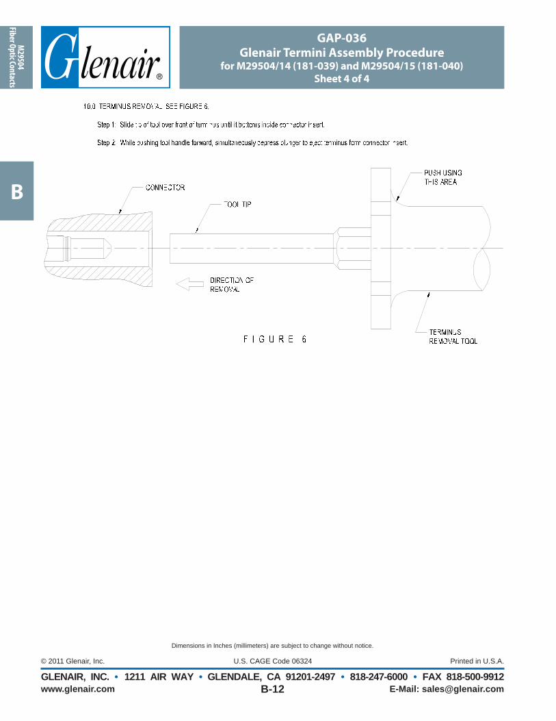
7. Insertion of Contacts:Insert wired contacts and tool into contact
cavity until contact “clicks” into retention clip (Figure 7). A straight pull on the wire will assure the contact is properly seated. Note: Isopropyl alcohol may be used as a lubricant. Use sparingly.
8. Assembly:After all contacts are inserted, assemble
backshell or strain relief according to Glenair backshell catalog instructions.
Contact Extraction1. Contact Extraction:
Remove backshell or strain relief from connector.
2. Contact Extraction:MIL-DTL-28840 connector contacts are
extracted from the rear but released from the front of the connector. Using an extraction tool, slide tool tip into front of contact cavity (mating face of connector, fi gure 8) until tool tip engages against contact retention clip. Push plunger with minimum force to release contact (Figure 9). Note: Isopropyl alcohol may be used as a lubricant. Use sparingly.
3. Contact Extraction:Pull wired contact from rear grommet of
AccomodationMilitary Part Number Glenair Part Number
20 28-32 AWG M39029/83-451 850-004-20-451
20 22-26 AWG M39029/83-450 850-004-20-450
20 20-24 AWG M39029/83-508 850-004-20-508
Standard Pin Crimp Contact for MIL-DTL-28840 Connectors
M28840
32
G
3rd
ManufacturerSymbol
Color Bands
Ø .077± .001
Ø .088± .001
5°0°
30°±5°
Ø .069 ± .001
Ø .047 ± .002
Ø .069 ± .001
Ø .064 ± .003
.180±.010
45°±2°
Ø “C” Thru One Side Only
Ø “B”
Ø .040 ± .001
.020 SR.015
Ø .020.005 Flat
.206± .002
.060 ± .003.033/.029
.187± .002
.092± .003
.497± .005
.202± .003
R .006.003
2nd1st
Material and FinishPin Contact: copper alloy per ASTM B197, 50 microinches gold plated per ASTM B488 Type II Code C Class 1,27 over nickel plate per QQ-N-290 Class 2, 50-100 microinches. Approved for space fl ight.
MIL
-DTL
-288
40In
trod
ucti
on
D
www.glenair.com E-Mail: [email protected], INC. • 1211 AIR WAY • GLENDALE, CA 91201-2497 • 818-247-6000 • FAX 818-500-9912
D-9
Dimensions in Inches (millimeters) are subject to change without notice.
Durability(meets SAE-AS39029, paragraph 3.5.9)No electrical or mechanical defects after 500 cycles of engagement and disengagement
Contact Retention(meets MIL-DTL-38999, paragraph 3.23)The axial displacement of the contact shall not exceed .012 inch (0.30 mm).No damage to contacts or inserts shall result.
Pin Engagement End(meets SAE-AS39029 paragraph 3.4.1)Unless otherwise specifi ed, the mating end of all contacts (except size 22 and smaller) shall be formed with an approximate spherical radius.
Permeability (meets SAE-AS39029, paragraph 3.5.1)When tested as specifi ed in paragraph 4.7.2, the relative magnetic permeability of the contact shall be no greater than 2.0.
Vibration(meets SAE-AS39029, paragraph 3.5.10)When contacts are tested as specifi ed in paragraph 4.7.11, there shall be no electrical discontinuity of 1 microsecond or greater. There shall be no defects detrimental to the mechanical or electrical performance.
Salt Spray (corrosion)(meets SAE-AS39029, paragraph 3.5.12)When tested as specifi ed in 4.7.13, mated contacts shall withstand 48 hours of salt spray conditioning without defects detrimental to the mechanical or electrical performance.
Temperature life
(meets SAE-AS39029, paragraph 3.5.13)When tested as specifi ed in paragraph 4.7.14, mated contacts shall withstand temperature conditioning for 1,000 hours without defects detrimental to mechanical or electrical performance. There shall be no diff usion/migration of the base metal through the contact outer plating.Class A - Maximum operating temperature +125°C. per paragraph 1.2.2
Dielectric withstanding voltage
(meets SAE-AS39029, paragraph 3.5.19)When tested as specifi ed in paragraph 4.7.20, crimped contacts shall show no evidence of breakdown or fl ashover.
Workmanship
(meets SAE-AS39029, paragraph 3.7)Contacts shall be processed in such a manner as to be uniform in quality and shall be free from foreign material and burrs or sharp corners that might damage the connector or aff ect mating of the contacts. Burrs and sharp edges shall be removed 0.005 inch maximum.
MIL-D
TL-28840Introduction
D
www.glenair.com E-Mail: [email protected], INC. • 1211 AIR WAY • GLENDALE, CA 91201-2497 • 818-247-6000 • FAX 818-500-9912
D-10
Dimensions in Inches (millimeters) are subject to change without notice.
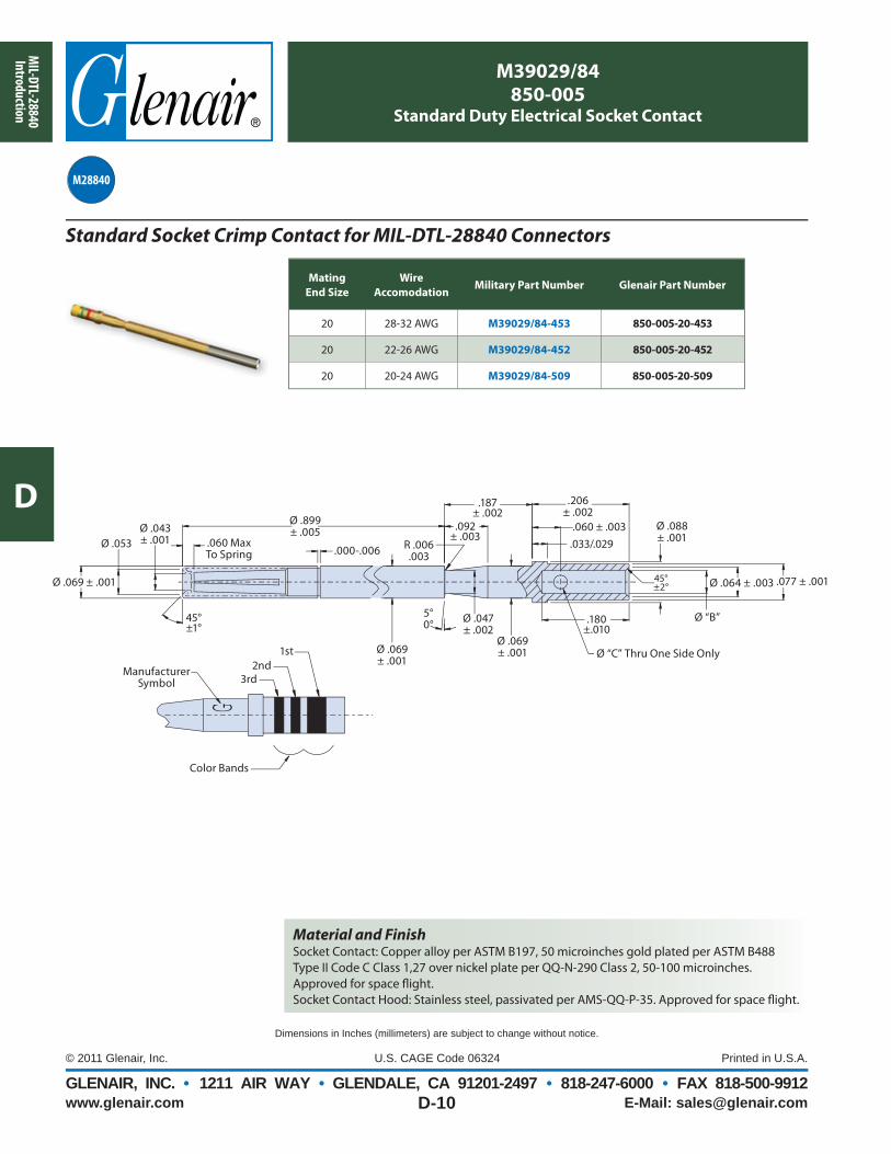
AccomodationMilitary Part Number Glenair Part Number
20 28-32 AWG M39029/84-453 850-005-20-453
20 22-26 AWG M39029/84-452 850-005-20-452
20 20-24 AWG M39029/84-509 850-005-20-509
Standard Socket Crimp Contact for MIL-DTL-28840 Connectors
M28840
.000-.006
Ø .043± .001Ø .053
Ø .899± .005
5°0°
45°±2°
Ø .069 ± .001
Ø .047 ± .002
Ø .088 ± .001
Ø .069 ± .001
Ø .064 ± .003
.180±.010
45°±1°
Ø “C” Thru One Side Only
Ø “B”
Ø .069 ± .001
.060 MaxTo Spring
.206± .002
.060 ± .003.033/.029
.187± .002
.092± .003
.077 ± .001
R .006.003
G
3rdManufacturer
Symbol
Color Bands
2nd1st
Material and FinishSocket Contact: Copper alloy per ASTM B197, 50 microinches gold plated per ASTM B488 Type II Code C Class 1,27 over nickel plate per QQ-N-290 Class 2, 50-100 microinches. Approved for space fl ight.Socket Contact Hood: Stainless steel, passivated per AMS-QQ-P-35. Approved for space fl ight.
MIL
-DTL
-288
40In
trod
ucti
on
D
www.glenair.com E-Mail: [email protected], INC. • 1211 AIR WAY • GLENDALE, CA 91201-2497 • 818-247-6000 • FAX 818-500-9912
D-11
Dimensions in Inches (millimeters) are subject to change without notice.
Durability(meets SAE-AS39029, paragraph 3.5.9)No electrical or mechanical defects after 500 cycles of engagement and disengagement
Contact Retention(meets MIL-DTL-38999, paragraph 3.23)The axial displacement of the contact shall not exceed .012 inch (0.30 mm).No damage to contacts or inserts shall result.
Pin Engagement End(meets SAE-AS39029 paragraph 3.4.1)Unless otherwise specifi ed, the mating end of all contacts (except size 22 and smaller) shall be formed with an approximate spherical radius.
Permeability (meets SAE-AS39029, paragraph 3.5.1)When tested as specifi ed in paragraph 4.7.2, the relative magnetic permeability of the contact shall be no greater than 2.0.
Vibration(meets SAE-AS39029, paragraph 3.5.10)When contacts are tested as specifi ed in paragraph 4.7.11, there shall be no electrical discontinuity of 1 microsecond or greater. There shall be no defects detrimental to the mechanical or electrical performance.
Salt Spray (corrosion)(meets SAE-AS39029, paragraph 3.5.12)When tested as specifi ed in 4.7.13, mated contacts shall withstand 48 hours of salt spray conditioning without defects detrimental to the mechanical or electrical performance.
Temperature life
(meets SAE-AS39029, paragraph 3.5.13)When tested as specifi ed in paragraph 4.7.14, mated contacts shall withstand temperature conditioning for 1,000 hours without defects detrimental to mechanical or electrical performance. There shall be no diff usion/migration of the base metal through the contact outer plating.Class A - Maximum operating temperature +125°C. per paragraph 1.2.2
Dielectric withstanding voltage
(meets SAE-AS39029, paragraph 3.5.19)When tested as specifi ed in paragraph 4.7.20, crimped contacts shall show no evidence of breakdown or fl ashover.
Workmanship
(meets SAE-AS39029, paragraph 3.7)Contacts shall be processed in such a manner as to be uniform in quality and shall be free from foreign material and burrs or sharp corners that might damage the connector or aff ect mating of the contacts. Burrs and sharp edges shall be removed 0.005 inch maximum.
GLENAIR, INC. • 1211 Air Way • Glendale, CA 91201-2497 • Tel: 818-247-6000 • Email: [email protected] • www.glenair.com
THE RUGGEDIZED, ENVIRONMENTAL MIL-DTL-28840 SOLUTION
Glenair off ers a fully tooled, high availability line of MIL-DTL-28840 shipboard electrical connectors. Developed for Navy shipboard applications, the MIL-DTL-28840 is a high-density environmental circular connector series which utilizes a high shock threaded coupling system, front release crimp contacts, RFI/EMI shielding, scoop-proof shells,
and corrosion resistant materials and fi nishes. Glenair manufactures all of the connector types and styles, as well as all of the backshell accessory slash numbers—the full range of MIL-DTL-28840 QPL connectors and accessories.
MIL-DTL-28840
MIL-
DTL-2
8840
Ele
ctric
al Co
nnec
tors
E
www.glenair.com E-Mail:[email protected], INC. • 1211 AIR WAY • GLENDALE, CA 91201-2497 • 818-247-6000 • FAX 818-500-9912
E-1
Dimensions in Inches (millimeters) are subject to change without notice.
ChainAttachmentStyleA - Link Chain with FastenerB - Link Chain with Ring for Jam-Nut Mounting ReceptacleC - Link Chain with Ring for Cable-Connecting Receptacle
M28840/13 Receptacle Cover
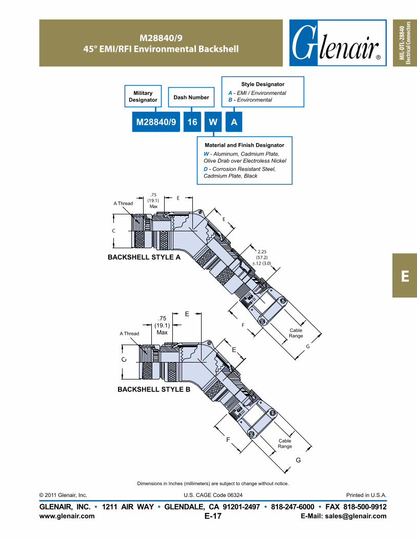
F
Gasket
E Thread
.780 (19.8)Max
5.0(127.0)
AttachmentStyle AJ Dia
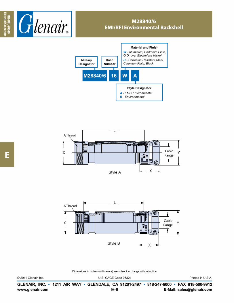
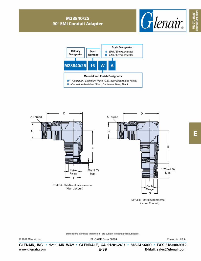
MaterialandFinishW - Aluminum, Cadmium Plate,
O.D. over Electroless NickelD - Corrosion Resistant Steel,
Cadmium Plate, Black
MIL-DTL-28840
Electrical Connectors
E
www.glenair.com E-Mail:[email protected], INC. • 1211 AIR WAY • GLENDALE, CA 91201-2497 • 818-247-6000 • FAX 818-500-9912
E-26
Dimensions in Inches (millimeters) are subject to change without notice.
VARIANCE CHARTTG-70 Strap Wrench Used with Glenair Torque Wrenches
AccessoryShell Size
08/0910/1112/1314/1516/1718/1920/2122/2324/25
283236
TG70 Torque282830303030757575
Part Torque353540404040808080
TG70 Torque45707575757595
120*120*135*150*150*
Part Torque6080
110 [80]120 [80]120 [80]120 [80]140 [100]
140140150150150
Recommended Installation TorqueLight/Medium Duty
± 5 Inch PoundsHeavy Duty
± 5 Inch Pounds
* TG70 Not Recommended For Values of 120 Inch Lbs. or Greater.
VARIANCE CHART NOTES1. Recommended installation
torque is approximately 80% of MIL-C-85049 accessory thread strength values.
2. Heavy duty installation torque values may be difficult to attain with the TG70 Strap Wrench; the values shown in brackets [ ] are the maximum attainable with the TG70 Strap Wrench using a single wrap.
3. Glenair recommends using 600 series torque tools whenever possible. When torque loading exceeds 75 inch pounds, or to attain the heavy duty torque values shown, a double wrap strap provides suitable friction to achieve torque values.
4. Glenair recomends that heavy duty torque values be directly read through the connector shell body with the use of 600-005 connectors holding tools.
BasicPart
Number
TG70 - 1 - 18
Strap Length in Inches (See Notes2 and 4)Lengths Available: 12, 18, 24 and 36-Inch Only
Standard length is 12 Inches, Omit Dash Number for Standard
Torque Wrench(Omit for None)
3.000 (76.2) Dia. Max. with 18 Inch Single Strap2.000 Dia. (50.8) Max. with 12 Inch Single Strap
3.000 (76.2) Dia. Max.
3/8 Square Drive,For Torque Wrench 600-004
6.500 (165.1) Approx
GLENAI R I NC. TG70
3.000 (76.2) Dia. Maxwith 36-Inch Single Strap2.000 Dia. (50.8) Max.with 24-Inch Single Strap
3/8 (9.5) Square Drive for Torque Wrench 600-004
See Note 2
See Notes 2, 4 and 5
APPLICATION NOTES
1. These wrenches are made of the following materials:Wrench Handle - Aluminum Alloy/Nickel Plate.Wedge - Stainless Steel/Passivated.Strap - Impregnated Fabric. Straps are 1/2 inch (12.7) in width.
2. Replacement straps are available. Specify part number G70515-xx for 12, 18, 24 or 36-inch strap. 24 and 36 inch for double wrap.
3. Metric dimensions (mm) are indicated in parentheses.4. Double wrap as shown for heavy duty range.5. Not recommended for composite coupling nuts (use 600-091 or 600-157).
Heavy Duty(Double Wrapped)Light/Medium Duty
Com
m Eq
uiv 2
8840
Co
nnec
tors/
Acce
ssor
ies
F
www.glenair.com E-Mail: [email protected], INC. • 1211 AIR WAY • GLENDALE, CA 91201-2497 • 818-247-6000 • FAX 818-500-9912
F-17
Dimensions in Inches (millimeters) are subject to change without notice.
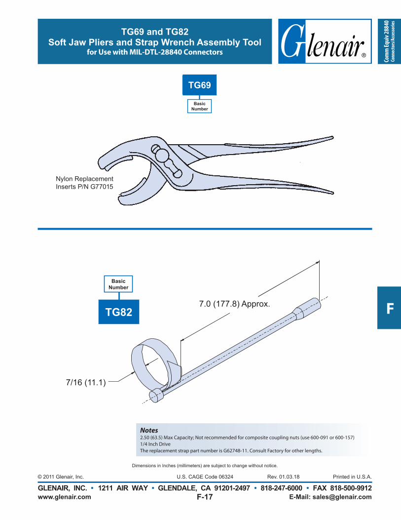
TG69 and TG82Soft Jaw Pliers and Strap Wrench Assembly Tool
for Use with MIL-DTL-28840 Connectors
7/16 (11.1)
7.0 (177.8) Approx.
Basic Number
TG82
Notes2.50 (63.5) Max Capacity; Not recommended for composite coupling nuts (use 600-091 or 600-157)1/4 Inch DriveThe replacement strap part number is G62748-11. Consult Factory for other lengths.
Basic Number
TG69
Nylon Replacement Inserts P/N G77015
Rev. 01.03.18
GLENAIR, INC. • 1211 Air Way • Glendale, CA 91201-2497 • Tel: 818-247-6000 • Email: [email protected] • www.glenair.com
NAVY CONNECTORS, TERMINI, NAVY CONNECTORS, TERMINI, ACCESSORIES AND TOOLSACCESSORIES AND TOOLS
RUGGEDIZED, ENVIRONMENTAL INTERCONNECT SOLUTIONS
Glenair offers a complete line of Navy connector solutions: From QPL’d MIL-PRF-28876 fi ber optic connectors for today’s high-speed ship-to-shore communications, to qualifi ed MIL-DTL-28840 shipboard electrical connectors and accessories for ruggedized environmental
shipboard interconnect systems, to precision tools for crimping and termination. The products are fully tooled and many are ready for immediate, same-day shipment.
MIL-QPL’D AND COMMERCIAL EQUIVALENT
6 ed
Inde
x
G
www.glenair.com E-Mail: [email protected], INC. • 1211 AIR WAY • GLENDALE, CA 91201-2497 • 818-247-6000 • FAX 818-500-9912
Index-1
Dimensions in Inches (millimeters) are subject to change without notice.
Glenair offers both Military S t a n d a r d 8 3 5 1 3 M i c r o - D connectors as well as COTS selections, backshells, mounting hardware and more. Our TwistPin contact provides superior performance.
EMI/EMP Filter
Connectors
MIL-DTL-38999 type EMI/EMP filter connectors, as well as other Military Standard and commercial electromagnetic shielding technologies. Also inc ludes Glenai r Ser ies 80 “Mighty Mouse” fi lter products.
Fiber Optic
Interconnect Solutions
Tactical fi ber optic connectors, cables, and termini for airframe, shipboard, and military ground vehicles. Catalog features Glenair’s innovative high-density (GHD) connector system for reduced size and weight applications.
The world’s broadest selection of in ter con nect
products–in stock and ready for immediate same-day shipment
Available now:
Glena ir's
In ter con nect
ProductGuide CD,featuring our
entire library of
Glenair catalogs
and data sheets.
In addition to over a dozen product line catalogs,
the CD includes a powerful part number
development program that takes all the pain
and confusion out of ordering interconnect
components. An easy-to-use inventory search
program provides ready access to 60,000 MIL-
STD and commercial part numbers.
Visit us at www.glenair.com and use the literature order form for immediate catalog fulfi llment
Series 80 “Mighty Mouse”
Connectors and Cables
G l e n a i r ’ s r e v o l u t i o n a r y connector series that reduces interconnect system size and weight by 50% compared to MIL-DTL-38999 connectors. Now used on hundreds of mission-critical military and commercial applications.
Miliary Standard
Connector Accessories
If the MS connector accessory you need isn’t in here – it doesn’t exist. Search this easy-to-use catalog by accessory type or Mil-Spec slash number, then place your order against Glenair’s 60,000 part number same-day inventory.
Glenair's World of
Interconnect Solutions
A complete over v iew of Glenair's innovative range of in ter con nect products and ser vic es, including Mil itary S t a n d a r d a n d c o m m e r c i a l equivalent connectors and accessories.
A World of Interconnect SolutionsU n i t e d S t a t e s U n i t e d K i n g d o m G e r m a n y F r a n c e N o r d i c I t a l y S p a i n J a p a n
Series 80“Mighty Mouse”
Composite Ther mo plas tic
Interconnect Solutions
Glenair is the world's leading manufacturer of composite interconnect solutions. We are the ‘go-to’ supplier for advanced composite technologies for c o m m e r i c a l a n d m i l i t a r y interconnect applications.
EMI/EMPFilter Connectors
U n i t e d S t a t e s U n i t e d K i n g d o m G e r m a n y F r a n c e N o r d i c I t a l y S p a i n J a p a n
High-Reliability Military Standard and Commercial Connectors for EMI Suppression
2 n d E d i t i o n • S e p t e m b e r 2 0 0 8
d dtandard anor EMI Sup
U n i t e d S t a t e s U n i t e d K i n g d o m G e r m a n y F r a n c e N o r d i c I t a l y S p a i n J a p a nU n i t e d S t a t e s U n i t e d K i n g d o m G e r m a n y F r a n c e N o r d i cc I t a l y S p a i n J a p a n
Fiber OpticInterconnect SolutionsTactical Fiber Optic Connectors, Cables and Termini
U n i t e d S t a t e s U n i t e d K i n g d o m G e r m a n y F r a n c e N o r d i c I t a l y S p a i nU n i t e d S t a t e s U n i t e d K i n g d o m G e r m a n y F r a n c e N o r d i c I t a l y S p a i n
Mil-SpecBackshells andConnector Accessories
A World ofInterconnect Solutions
Glenair, Inc.1211 Air Way • Glendale, California • 91201-2497