This document represents candidate "Thrust Structure Concepts" and the"Integrated Health Monitoring Screening" for the Graphite Composite PrimaryStructure. This report satisfies the requirements of Milestone 4 of TA2(Cooperative Agreement NCC1-193).
ii
zI
i_i_i'_i!i_i__i_ii!,_,
_i _i,__ _! __i_
i i¸il¸¸¸¸ i !_!_ L¸
_i I,
_ Li i_
i__ _
iiii_!i!iii
• IL i _ .i I _ _
Integrated Health MonitoringSensor Screening
TA2 GCPSTask 7, Subtask 2
, L_ :_i,.,_,
i_ _i! _ii ii._
_iii__i_i_i_i:i(i:_:: _!•i!ii_:ii _ i
! _i̧•,iii :
!
i: :il /i: ¸¸
_L i iiii_!_/::_
_iii_:i:ii:iii_i/__!
..i: i-!!
i•i ¸ • i!
,i
,<:, <
: j_iii:•i_i_
> / i
SSTO THRUST STRUCTURE
MILESTONE 4, TASK 4
TASK DESCRIPTION:
SELECT UP TO THREE PROMISING THRUST STRUCTURE
CONSTRUCTIONS AND SELECT MATERIALS FOR SCREENING TESTING!
SUMMARY OF TASK 4 ACCOMPLISHMENTS.THRUST STRUCTURE CONCEPTS
The thrust structure concepts selected are shown on the attached figures.These concepts are dependent on the vehicle concept considered. A reinforced
conical shell is proposed for all vehicle concepts except no. 4. The primaryconsideration here, since the fuselage cross section is round and the aft tank is
near the thrust structure, is to distribute the engine loading into the fuselage asuniformly as possible.
Two concepts are shown for vehicle concept no. 4. The first is a truss type
structure, assuming a breadloaf type fuselage interface and the second is againa reinforced conical shell. Vehicle concept no. 4 differs from the others in that
the payload bay is in the rear and heavier point loads can be introduced into the
fuselage, since a greater distance is available to shear these into the fuselageskins.
CONCEPT FOR BASELINE VEHICLE 2A
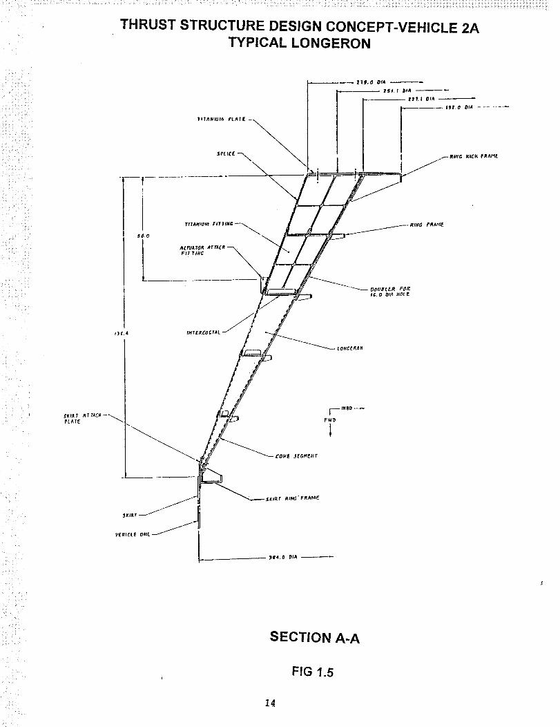
The first concept, shown in Figures 1.1 through 1.5, consists of a truncated
conical shell with two external Iongerons, supported by interior flames, at each
engine location. An aft frame serves to support and react the engine mountingforces while the forward frame interfaces with the vehicle skirt. Four
intermediate frames are provided for stability. Stringers between the Iongeronsets, which are only shown schematically on the sketches, will be spaced as
required. The details of the Iongerons/stringers/frames and skin panels will bedeveloped in subsequent work.
This concept will be our baseline, applicable to vehicle 2A, but will be
representative of the design for all vehicles except concept no. 4. In this
concept the heavy engine thrust loads would feed directly into paired Iongeronsand be sheared into the skin over the length of the Iongerons. The goal here
would be to distribute the axial load on the forward frame, and eventually the aft
tank, as uniformly as possible. Also in this concept, the thermal protection
blanket would be attached directly to the thrust structure walls. Two Iongerons
are shown for each engine. Sets of Iongerons are separated by stringers, whichwill be optimally sized and spaced. External Iongerons were chosen over
internal ones. External versus internal Iongerons provide a 12% reduction in
skin area and an 8% reduction in frame length. Pumps and propulsion boxes
would be on the outside of the shell making them accessible after removing
access covers. Also there would be no penetration of the thrust structure shell
by hot gases. An insulated secondary structure would close out the plane of theaft frame, which supports the engine thrust pads.
Composite materials will be utilized on all thrust structure components whereverfeasible. The principal load carrying fittings will be metal, probably titanium,interfacing with composite structure where it is feasible. The Iongerons,stringers, frames and stiffened skin panels should be of composite construction.
Material selection is still in progress, however the present baseline composite is977-2/IM7 epoxy/carbon.
FIRST DESIGN FOR VEHICLE CONCEPT NO. 4
This design concept is represented by a truss type structure as shown in Figures
2.1 through 2.2. This design would be applicable to vehicle concept no. 4 only.The vehicle concept here would feature a breadloaf section for the aft payloadbay area which interfaces with the thrust structure. The truss design isappealing for this vehicle concept since the payload bay is in the back. The
heavy truss loads can be transferred directly into the Iongerons of the payloadbay and sheared out into the skin over a considerable distance before the tank
wall is encountered. This insures that a fairly uniform loading on the externalshell will be obtained forward of the tank wall. Since this is a truss typestructure, the heavy loads will remain in the truss members and be imposeddirectly on the aft bulkhead of the payload bay. From there they will be shearedinto the payload bay shell by Iongerons and stringers in the payload bay area. Astiffened bulkhead will close out the aft end of the payload bay area. This willserve to reinforce the truss structure. Secondary structure panels will berequired between the Iongerons to closeout the truss structure and will serve to
mount the insulation blankets and some of the system hardware. The enginemounting plane shown in figure 2.1 will contain structural beams which willreinforce the truss structure and support close-out panels and thermal insulation.
Again composites will be utilized where feasible. The fittings should be metallic,probably titanium. The truss rods will be composite where possible. Materialsand construction details are still to be determined.
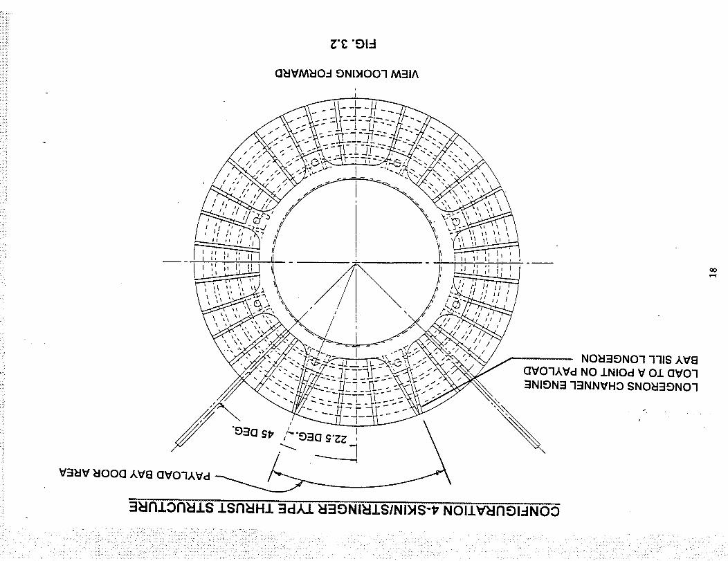
SECOND DESIGN FOR VEHICLE CONCEPT NO. 4
This design concept is represented by a conical shell using skin/stringer typeconstruction, as shown on figures 3.1 and 3.2.. It differs from the previousvehicle no. 4 concept in that the payload bay interface with the thrust structure is
circular, rather than a breadloaf section. This concept, using a skin/stringerconical shell, is much like that for vehicle 2A, except that it does not have to
distribute the axial loading as uniformly into the aft frame of the payload bayarea, since the tank interface is forward of this section. The cutout for the
!!_i!i!'iii_!ii_i'il _
'i!iilli̧ili
_!i_i_'__ili_ii!_!_
payload bay doors ,at the top of the fuselage, cannot carry axial load. This
concept avoids loading that area by bringing the load from the two upper pairedengine support Iongerons into a point at the aft end of the payload bay sillIongerons. The aft frame of the payload bay section should not receive
substantial axial load from the engine thrust loads in the area of the payload baydoors. Again, as in the previous design for vehicle no. 4, the wing is beneaththe fuselage.
The discussion of design details will be much the same as for concept 2A, withthe exceptions noted above.
The materials will also be composite where feasible and very similar to thoseconsidered for vehicle 2A.
Materials will be selected for preliminary screening. The materials selected will
be those that are considered most suitable for the thrust structure cone,Iongerons, engine support fittings and frames. A variety of manufacturingprocesses will be considered for the fabrication of these parts. Due to the sizeof some of these structural components onlya few processes can be considered
as applicable for their fabrication. These processes, in turn, limit the applicablematerials.
The selection process to determine a candidate materials will involve thefollowing considerations:
1. The primary weight parameter is specific compressive strength.Specific tensile strength and specific stiffness are also considerations.2. Maximum material hot/wet operating temperature.
3. Material toughness. This is a consideration, however impact shouldnot be as significant a factor due to the heavy composite sectionsanticipated in this design.
4. Suitability of the material to the proposed manufacturing processes.Material out-time will also become a major consideration for thefabrication of the large structures required.
5. The maturity of the material system is an important consideration
together with the risk involved in using a non-mature system.6. Moisture should be less of a problem due to the thickness of the
laminate sections, since it would appear that fully moisturizing the actualstructure would be difficult to accomplish.. However to be conservativethe hot, wet allowables will be used.
7. Resistance to hydraulic fluids, etc. should be less of a problem due tothe stated goal of reducing the use of such fluids wherever possible.8. Reparability of the material system will be considered but will not bea major weighting factor.
9. Cost will not be considered a major factor unless it is disproportionateto the other material/process combinations.
It should be noted that only a short period of time is available for the selection
and testing of these materials. Materials considered must have current usageand be available in time to support the test schedule. Thus many materials willbe de-selected on this basis. To satisfy the requirements above the material
system categories listed below have been selected as screening candidates forthe thrust structure
1. Conventional carbon/epoxy systems. One of these, 977-2/IM7, will be
considered as the baseline material. These materials can exhibit highspecific strength, high toughness and temperature capabilities up to300 degrees F, when properly formulated. 977-2/Im7 however is limitedto approximately 230 degrees F usage.
• ill _
i!'!iiii._ii_,,'ili_i_!
:!i_,: :_:_:i__
_iiii_il._{i_!i_'_-_i_ i, • _,I_
i,!_i_i_•_
i _ i:i!
2. Higher temperature systems-such as carbon/BMI, capable oftemperatures up to 400 degrees F.
3. Low temperature cure resins with carbon fibers - For possible
application to non-autoclave, low temperature curing of the thrust
structure shell. The size of this structure may dictate the considerationof such a process.
4. Materials for application to the pultruded rod process-Such as high
strength carbon fibers with thermoplastic resins. These might have
Iongeron applications, if sufficient compression capability can be shown.
5. Boron fiber hybrid systems with suitable resins might also offer:potential for Iongeron applications.
SELECTION OF SYSTEMS
_i_ •_i_iii_
Conventional Carbon/Epoxy Systems-
The baseline for this structure has been agreed as Fiberite 977-2/IM7. It is an
advanced toughened system and the IM7 offer good fiber properties. One other
system might be selected from this group. Candidates are 977-3/IM7, Hexcel3900/IM7 or Toray's 3900/H800.
• _iI/,
i
Hi clh Temperature Material
Candidate materials evaluated for higher use temperatures, included both
Bismaleimides and Cyanate Esters. Polyimides were initially considered, but itwas determined that the higher operating temperature was not needed.
Because of the following rationale, BMI materials were chosen for the highertemperature applications.
BMI materials meet the operating temperature criteria.A larger database exists for the BMI materials.
The BMI systems are more mature.
The BMI systems are more readily available.Total cost is less for the BMI systems.
Candidate BMI systems included Narmco 5250-3, 5250-4. Narmco 5250-3 is the
baseline for the wings of the vehicle. The F22 uses Narmco 5250-4.
Narmco 5250-4 with IM7 fibers was selected as the BMI candidate material since
-3 was found to be unavailable within our project timetable. Also it has a muchlarger database.
'ii_i_i_iiii!i_i!!!ili_ii_
_iii_iilii__iiilil_
iii iiiii !!
_iii_ili__ !i_i_i_
• :_ii! ¸
!:i! __i:iiii_
,Low Temperature Curin,q Materials
These resins are being considered because of their out of autoclave, lowtemperature, processing. Advanced Composites LTM resins are available
locally and can be received on a just in time basis. Both LTM series 20 and LTMseries 40 resins are toughened epoxies.
The LTM 20 series materials has a marginal Tg. LTM 40 series is a more highlytoughened system. Of that group LTM4_5 has _ larger database, but has an out-
time of 5-6 days. LTM 48 has similar properties, but has an out-time of 30 days.It is necessary to have the longer out-time for fabrication of large structures,
such as the thrust cone. The supplier of these materials, Advanced CompositesGroup inc., recommended their MT9F system, another member of the LTM40
series, over the LTM45 or LTM48. It has an out time comparable with LTM48,
has good 270 degree F wet and CAI properties, and has greater usage with a
larger database.. Thus the LTM45 and LTM48 were eliminated, and the onlyremaining low temperature curing material candidate was MT9F. This will beconsidered with IM7 fibers.
Pultrusions
_ ii!_ I
i i _ _
:i_ _ ii:_il _
Pultrusion is an automated process. Since we are dealing with large structures,
automation of the process is a plus. Higher fiber volumes and straighter fiberorientation, can be achieved using the pultrusion process. Pultrusion is a viable
candidate process for truss structure or for Iongeron stiffening, if acceptablecompression properties can be obtained.
Thermoset and thermoplastic resins can both be pultruded. Because of cure
characteristics vs a process dictated cure time, the number of thermoset resins
that lend themselves to the pultrusion process is limited. Most thermoset resins
that can be pultruded do not have the required mechanical properties .The
DMLCC program is evaluating a pultruded thermoset rod made by Neptco. This
rod is not acceptable for this program, due to a dry use temperature of 220F.
Thus only the thermoplastics will be considered for the pultrusion applications.
Most composite thermoplastic resins, including Polyphenylene Sulfide (PPS),
and PEEK, have a use temperature that is lower than required for this program.For this reason, PEKK is probably the only viable thermoplastic candidate for
this application. PEKK will be evaluated with either M7 or AS4 fibers and withHybor/IM7 hybrid fibers.
Fibers
Both IM7 and IM9 fibers can be impregnated with a thermoplastic or thermosetresln The baseline fiber chosen is IM7. IM9 was investigated, but wasdiscarded for the following reasons..
The increase in properties was not as much as initially thought.
IM9 is not as mature and does not have a large database.IM9 is not readily available in large quantities.
Published data for a hybrid boron/carbon fiber manufactured by Textron
indicates superior compressive strength. This material can be impregnated with
either thermoplastic or thermoset resin. This is another option that is beingconsidered. The thermoplastic resin will be PEKK and the thermoset resin will
be NCT301. Textron has a lot of experience with this resin system.
Application of integrated health management (IHM) to the composite primary structureof a launch vehicle is necessary to reduce operational costs and processing timedelays. This is accomplished in two ways: Firstl enforce robust design of thecomposite structures to provide the confidence to eliminate many inspectionprocesses, and second, to apply appropriate nondestructive evaluation and inspection(NDE/I) sensors to handle the fault n_odes which will inevitably occur. Even withsuccessful development of robust structural designs some form of monitoring will benecessary to detect and identify external threats to the structural integrity andevaluation the impact of damage sustained during operation.
Part of the NDE/IHM task is to acquire and develop (if necessary) NDE/I sensortechnologies and to integrate those sensors into the full scale test articles (FSTA)which will be produced under the T_ program: This effort will not only develop thesensing technologies necessary; but also provide a knowledge base of directexperience, for the implementation of an integrated health management (IHM) systemfor an operational flight vehicle.
The NDE/I sensor screening is intended to serve as a first cut to reduce the number ofcompeting sensor technologies to several promising candidates Three or four of themost applicable technologies will be retained for further investigation anddevelopment, through laboratory testing of instrumented coupons and panels, whilethe others will be noted for future reference, it is intended that this evaluation bereassessed periodically to ensure that technological developments, which could alterthe findings, are incorporated as the program proceeds.
Discussion
The NDE/I sensor screening is driven by the need to assess the structural health of the
composite primary structure of the Full-Scale Test Articles (FSTA) for the wing,intertank, and thrust structure of a single-stage-to-orbit (SSTO) launch vehicle.Inspection of these structures by conventional means is complicated by three factors:(1) the composite material properties differ significantly from metallic materials, (2) theprimary structure of an operational SSTO will be covered by a thick thermal protectionsystem (TPS) which prevents direct access to the structural surface, and (3)conventional methods have been labor intensive and time consuming (especiallyinspection of the entire vehicle). Implementation of a highly autonomous IHM systemrelies on embedding as many of the sensors and data interpretation mechanisms onthe vehicle as is feasible. This system can then provide real time and continuous
structural health monitoring during all power on phases of the mission--including mostof the ground preparation tests and checkout--thereby eliminating much groundsupport equipment (GSE).
The TA2 NDE/I and sensor screening process approach was to conduct a literarysearch to provide the largest sample of available sensor technologies. Additionally,the NRA8-12 team members, government agencies (NASA, DOD, national labs),
2o
i _ :i!i_il ,:i_ • _,_
• _ ! • _i •
! il_ii_iillii_: _i_, _ •
aerospace and commercial industries were contacted to gather promising NDE/Isensor technologies for screening. Contacts were initiated with several NDE/I and
sensor technology vendors as well as research universities. Review of these inputsidentified eleven sensor technologies for evaluation and provided sufficientinformation about each technology to draw initial conclusions about the fitness ofindividual technologies to meet the TA2 Task 7 requirements.
The TA2 sensor technology screening ran in conjunction with similar surveys for TA1and TA3 to maintain an integrated approach to fault mode identification and NDE/Isensor selection.
Selection Criteria
The selection criteria for this first NDE/I sensor technology screening are based on a _hierarchical need list: (1) the sensor must be able to detect the fault modes of thecomposite primary structures; (2) the sensor (or technology) must be applicable to theintended operational environment; (3) the sensor hardware (and software) mustmature enough to meet the TA2 schedule with little or no development required; (4)the sensors must be affordable (development, operations) to implement on the full-scale test articles as well as an operational vehicle. One difficulty with the finalcriterion is the availability of the cost information. While many researchers andtechnologists are eager to share the technical merits of a particular sensingtechnology, they are either unaware of, or reluctant to divulge, their costs fordevelopment and implementation. However, relative estimates can be established bycomparing the maturity of the sensor technology (development cost), or, the number ofsensors and the amount of supporting hardware (cables, wiring, control, etc.) requiredto provide similar areas of coverage (implementation cost).
To effect selection of candidate sensor technologies, which will provide the greatestbenefit while incurring the least liabilities, four selection criteria were utilized: (1)detection capability (area of coverage, fault modes), (2) ground based and in-situ (on-board) application, (3) maturity (availability and development required), (4) operationalbenefit, liability, and relative complexity.
Sensor Technology Identification
The sensor technologies are divided into two categories: conventional and advanced.The conventional NDE sensor technologies are those that are available and/or
established methods, techniques, off the shelf equipment and training materials.Advanced sensor technologies build on the conventional technologies and in somemanner enhance the performance of the methods in either a generic or applicationspecific manner.
The conventional NDE sensor technologies include but are not limited to: resistivestrain gauge, ultrasonic, eddy current, x-ray, penetrant, and visual.
21
:,i_ • _.
:ii:i ii_
i • ii: ¸¸•
_ i:_i_i:, _ i _
_:_ :!i_/_ :_, iii _
:ii _ ii ii I,_
i_iii__,,iii_;i_Ii:?ii_i
Resistive Strain Gauoe - Electro-resistive strain gauges have been used within theaerospace industry for-many decades to measure flight loads on aircraft. The principlethat the electrical resistance of the sensor element (thin wire or photochemicallyetched conductor) is proportional to the length of the sensor element and hence thestrain of the bonded material. The prevailing design of strain gauges is to direct theconductor path back and forth parallel to the dire_ion of the strain measurement to
enhance the sensitivity of the detector. Usually several strain gauges are used indifferent orientations to provide a complete assessment of the st;-ain environment atthe sensor location.
control monitoring during the manufacturing and fabrication of the graphite primarystructure. Tests will evaluate capability and effectiveness and detect and quantifyflaws and damage such as porosity, cracks and delaminations. Contact ultrasonicinspection technology typically requires a coup|ant such as water, gel, or epoxy toprovide adequate energy transmission into the material. Specialized air scan systemsmay also be evaluated for capability to locate and quantify anomalies in integratedassemblies such as debonds between layers of insulation and substrate Ultrasonicinspection is routinely used during the manufacture of composite structures, but hasnot been applied to in-situ monitoring on flight vehicles.
,E_G[.cL_L_C_ - Eddy Current inspection is an electromagnetic process that measuresminute changes in the magnetic field (due to eddy currents in the test material)between two current carrying coils. The magnetic field was changed if the distance toor thickness of the measured conducting medium changes. Due to low conductivity,Gr/Ep materials do not respond well to eddy current examination. Metal matrix
composites also appear to respond to eddy current inspection. However, eddycurrent may not be a useful inspection technology for IHM of composite materialstructures unless adequate sensitivity can be demonstrated.
X-Ray Radiography - X-ray technology may be used as needed during manufacturingand fabrication to verify indications revealed by other NDE/I methods, but safety andcomplexity considerations rule it out as an IHM technology. Advanced radiographictechniques using computer enhancement to evaluate flaws in the materials and
structures may be employed to determine structural integrity during fabrication andwas evaluated for assessing materials for flaws during ground based maintenance.
Dye Penetrant - Penetrant technology may be used as needed during manufacturingand fabrication but will not be considered for use as an IHM technology. Penetrant is alabor intensive technology used primarily on metals. The detection sensor is theoperators' eyes and fluid penetration into the structure is to be avoided. Besides, thedevelopment cost of automating this process is out of the scope of this project.
22
Advanced NDE technologies build on the conventional NDE technologies and insome manner enhance the performance of the methods in either a generic orapplication specific manner. Examples include but are not limited to; acousticemission, laser based ultrasonic (LBU), fiber optics, shearography, thermography, andmicrowave. Usually these are technologies that offer a unique approach orapplication of state-of-the-art technology in innovative manners.
Acoustic Emission . Acoustic emissions are detected by attaching ultrasonictransducers to the surface of the material at strategic points to record the stressemissions generated within the structure. Low level sonic or ultrasonic emissions maybe generated by stress relief at cracks and flaws under load resulting in local materialdeformation, degradation or damage, in response to structure impacts and asa resultof leaks. (ref. 1) Emission in the structures generate characteristic pulses which can bemonitored to identify the type of flaw, the location and the rate of growth, AcousticEmission can be used to gather data during the manufacturing and test programs toestablish baselines for the detection of flaws generated during flight. The data is _gathered and reviewed by computer to monitor the integrity of the structures and tomonitor the growth of anomalies. This versatile technology is used as a tool to studymechanical behavior of materials, as an NDT technique and as a quality controlmethod. As an NDT method it is calibrated to a structure and then waits to detect andprocess low level events while the structure is under load.
Laser-Based Ultrasonic Inspection - Laser Based Ultrasonics is a non-contactingderivative of standard ultrasonic inspection. Ultrasonic pulse energy is introduced intothe test specimen by pulses of light from a laser. The reflected or transmittedultrasound pulse is detected with a fiberoptic interferometer that detects motion of thesurface. Laser generated pulses typically have much lower energy that contactultrasonics so frequency locking is used to filter the signal from the noise. Thisemerging technology was screened for IHM applicability. Preliminary test results of aGr/Ep panel using the Rockwell International LBU system shows positive results forIHM applicability.
- Fiberoptic sensors are a novel method for determining the health orcondition of composite structures. The optical fibers, which usually measure for stressor temperature, are imbedded into the composite structure. Continuous strainreadings can be made along the length of the fiber based upon the return time of thestrain signal. Temperature sensors usually have a series of nodes along the fiberlength. These sensors provide wide area coverage and are compatible to harshenvironments. They provide composite curing information and can provide continuousinformation during manufacture, testing and flight. The main drawback to thesesensors is the difficulty in replacing them if they should fail.
- Shearography is a form of interferometry that uses a laser to acquirestressed and stress free images of the test item. The nonstressed image is added inreal time to the stressed images to produce interference patterns, observable on a "IVmonitor, which indicate areas experiencing minute movements during the process.These patterns may be interpreted to indicate flaws such as cracks, delaminations,debonds and other anomalies. Shearography appears to be most effective withflexible rather than stiff rigid materials.
23
ThermooraDhy - Thermography is a remote non-contacting method utilizing infraredimaging sensors for detecting a variety of surface and subsurface material defects andfaults. Standard thermography is performed by heating a structure using quartz lamps(or equivalent) and scanning the surface of a structure with an infrared (IR) videocamera. The camera detects small variations in temperature, thus, providing imagesof thermal conductivity patterns in the test specimen. The images are evaluated toascertain if the patterns indicate anomalies such as surface flaws (pits and scratches),debonds, delaminations, cracks or other flaws. If the emissivity of the materials in theimage are known, actual temperatures can be quickly and easily calculated.
MJ.EC0._y__=- Microwave inspection is a form of radiography which holds tremendous
potential, Microwaves are generated and emitted from a non-contacting wave guidetoward the specimen. The microwaves penetrate dielectric materials (like TPS andGr/Ep composites) and reflect from various internal irregularities. Thus, the returnsignal contains three-dimensional data about the status of each material and bondlinewhich it encountered: Structural inspection with microwaves could occur while theTPS was still in place on the vehicle, However, like X-rays, there are safety concernswhich have not been quantified at this time which may limit the applicability ofmicrowave inspect in the ground based operations environment.
To gather data for sensor comparisons and selection of equipment and sensors, aSensor Capability Classification Matrix (Table 1) was developed. This is a summary ofthe aforementioned NDE/I technologies and their capabilities to detect faults in a Gr/Epcomposite structure. This matrix will continue to evolve as additional details becomeavailable and will be included it the TA2-Task 7 Development Test Plan updates.
To further assist in the selection of each method, the matrix was expanded to cross-reference the technology capability with the faults that are to be identified. This matrixwas designed to help identify the most promising sensor technology to detect thepotential fault modes.
24
Method
R_rve StrmnGmgo
Contact UltrasonicExamk_alk_n
Eck:/ycurrant9xarninat_n
X and G&_f,=aRad_n_phy
VisuaJ_ DyePenebant
Acous_c Emisslon
L.a_aTBa.sedUltrasonicExamination
FiberOpbcs
Therrr_graphy
Microwaveexamination
Table 1 Sensor Ca0ability Matrix
Comparison of Selected NDE Methods
Properties(Sensed or
Measured)_d_nad strmn
n ao0ustic
n_.causedin.eleclncal
near- isurface diso_tJnuilies ::
from voids, inclus_'_material variations,placement of internal:_u'_.
ln c...b._-_ivabietur_ (color, _-_ape,
pat_m, etc.)
n acous_c
.Chan_s Inacous_cimpeoanoe.
Changes n opl_eJattenual_n, fn_luencyshift, lime delay
In dlelecb¢_ _kCorcls,dela_inat_ons voids,and crad_In metal surfaces:surface cracks
Adva ntegee Limitations
=.mpie, .._._, very rna_m, Itn'_m:! _ _o(p_nge, masmJraslight _ units ex=t _ a singk_cirecli6n, not
_n._ive mough to dmct mo_tfaults
Exc_ent peneUal_, read,and _._ ooq_ing
upon oj_.ralor_I_I.m_ive::ins_.Rd_ _ laminar flaws
_ ampar_ to_ amidi
, pe_t retool if _ :pmetnd_-_, geomeW_nat_/e, mbrenm stanclan:Is
Detects _nternaJcLsox_n,.bas, _._ re_ve rk_'_smwty to _nuseful on a _Je variety of or larnim_ flaws such as fat_uematerials, portable, permanent crocks of delaminal_ns whichrecord are _lar to the
_am.health hazard
Low costecMpment. _ H_r_/clep_c_t on operatorin._o_ion _i,, _'_t_t contam_n,
rec_iras access to only o_e side,permanent record, ifneeded.
Conbnuous ooverage over length,in-sif_b_roughoutpn:_uction andoperation
Non-oontac_ng =r_pectx_, c_mctvisual display of irmgulad'oas
Refomnce sta'K_tcl USu_Iyr_uir_d, hi_ dspex_t _o_operator sk_ll,-relatJveinsensitivity to laminar flawswt_h are pandlet to the =K_,._:Ibeam
Near _ fault _eclKm only,diff_ult to replace or repeJr.
Less sen.,_tJvetor ng¢l materials, :difficultto uas in-sifu
Able to Oetect mlBmal flaws,direct visual imaging,
Requires _rect aasass to _
Noncontacbng, ma W au_ No penetmbon ot metals,rapid_, penetration of comp_mlively poor cle_ilion ofnonme_s_udingTPS nbleto flaws, hasllhl'm_mdimage multiple interfaceand intmTmldefects
25
Fault Mode Identification
The main tenant of the IHM philosophy states that the implementation must occur atthe lowest level possible to achieve maximum benefit. This means that the first step inimproving the health status of the system is to eliminate as many fault modes aspossible through robust design and controlled operational procedures. Experiencewith military and commercial aircraft which use composite structures indicate that arobust structural design is sufficient to eliminate the need to monitor most of thecommon fault modes (even ground crews). The faults which are large enough todetect before they are of sufficient size to endangering the structure and the vehicleare of primary interest as targets for in-situ IHM assessment. Four faults meet thisneed: cracks, delamination, debond, and surface damage.
Cracks - Cracks begin with a small discontinuities (voids, debonded fibers, chips orscratches in free edges, etc.) in the composite material and grow due to stressconcentration around the crack itself. The growth rate depends on the size of thecrack, its orientation, and the surrounding stress environment. Crack growth is themain fatigue mechanism which limits life.
IJ_.j_[zi_o_ - Delamination is a separation between ply lay-ups that occurs primarilydue to impact and boundary discontinuity around free edges. The delaminationresults in a decrease in compressive stiffness and is subject to rapid growth in cyclicloading environments since the inter-ply bondline is the weakest point of thecomposite.
- Debond arises from separation of joined structural elements (skin/stiffeners,lap joints, etc.). These elements will loose effectiveness as the debond grows due tostress concentration around the debond. Early detection of debonded elementsallows repairs to be made in a timely manner. Most debonds result from voids in thejoining adhesive or resin during manufacture, yet, debonds will result from impact andoverloading conditions on the vehicle as well due to bond failure.
Surface Damage - Surface damage occurs when foreign materials contact the
structure (e.g., scratches, pits, dents, erosion, penetrations, etc.) or through chemicalcorrosion. Surface flaws attract and retain moisture which can lead to corrosion andact as crack starts. Penetrations are particularly troublesome since environmentalfluids and gases can pass inside the structure where inspection and cleanup areespecially difficult.
Sensor Comparison
The sensor technology capabilities have been cross-referenced with the selectioncriteria and are in the following table.
26
1>3
Senior Technoloav
_eslsave Sbmn Guage
Ichanges in sent, or te_s_ance
due to s_n ot su_sbate I
Contacl Uf_ason,c Insp_ctio_
Ichanges in acoustic impedance
Eddy Current
changes in elec_ical and
_a_etlo i_0p_x6es}
K and Gamma Rad;ography
{changes in densityJ
Visual and Dye Pe.o_a.lt
Ichanges In observable features
Icolo_. shape, pattern, etc)l
_ccousbc Em,.;_..,s
changes m Icou_1o
mpedenceJ
_tset Geneqated Ulb_;_
nspecfron
{changes in aco_itc
impedance I
Fiber Opbcs
(changes in op_al atlo_ualJon,
frequency shift, and time defayl
Shearography
inte_fereqce patterns between
_c_loaded and loaded images}
Fhermograp_ly
changes in emmis_vtly _d
_lermal conducfivify_
time delayJ
Table 2. NDE Sensor Technology Comparison with Selection Criteria
sen_|wty and _elmlu|on sklti, reklbve ii_,l_ _lt_ity to
requires acce_ to only one laminar _ which are
side, permlnlmt record, if _ttlllel to _e Iound beam
needed
_x. wil decreale _Ir
"natority
C on tin uou_ oov_llge over Ne41_' freld laull detec_oq)
length _-s_tu throughout 0nly, dilicuit to replace or
produchon and opera_o_n repair
Vlod_ra_ly comple=,
_mbedding and
maintenance diffict Jl_es
Non-conlac_g inspection _r_t ecce_ to inspected Comptex
Iurflce requked, poor
resolulton of ov_leid fau_
matemlll
Yo_-contac_g in--on
No_contac_lg. reedJy
g lps)
Oke_ IC_mm Io _nl_o_1od _imple
lur face required, poor
tesdullon Of OVerlaid faul_l
No penetation of m et_ls.
Results
Review of the anticipated fault modes and the available sensor technology dataindicates that three sensor technologies should be assess for the in-situ monitoring ofthe composite primary structure elements. These are: ultrasonics (dry contact),acoustic emissions, and fiber optics (embedded or attached). In fact, a combination of
sensor technologies will be needed to detect and evaluate the fault modes; not only dosensor technology have specific capabilities and applicability, but, the three Gr/Epprimary structures being demonstrated under the TA2 effort have differingrequirements based on their respective failure modes and designs.
Ultrasonics was selected because it can detect all of the failure modes and compatiblewith in-situ operation. The sensors themselves are inexpensive and simple.Ultrasonics can survey a fairly large area by addition of more sensors and can work inconcert with other technologies such as acoustic emission.
Acoustic emission was selected for similar reasons. This technology is the onlytechnology that actually detects the damage happening with the sensitivity todetermine the energy being released (e.i., magnitude)
Embedded fiber optics have been used on recent military aircraft and the processesfor installation and data acquisition are well known. New and innovative detectors arebeing interfaced with the fibers to allow additional measurement capabilities. Fiberoptics can provide continuous monitoring along a length (like a bondline) and are bynature an in-situ technology.
Laser based ultrasonics is a ground based sensor technology that may be of interestfor rapid, non-contacting inspection of exposed (or removed) structural elementsduring the ground processing. The conventional suite of sensors (wet contactultrasonics, X-ray and radiography, and visual) are acceptable for the production,assembly, and repair of the structural elements when the in-situ systems areunavailable.
The next step is to bring these technologies into the laboratory environment and begincharacterization of the sensor output from the coupons and panels being constructedfor this task. During the interim, between completion of this screening and theavailability of dedicated test specimens, these sensor technologies will be non-intrusively added to ongoing tests for other tasks and projects where available.Development of sensor interfaces with the data collection system will also take place.This effort will be coordinated with the TA1 and TA3 tasks to ensure that maximumadvantage of resources and testing opportunities is achieved.