328
FM 3-97.61(TC 90-6-1) MILITARY MOUNTAINEERING AUGUST 2002 HEADQUARTERS DEPARTMENT OF THE ARMY DISTRIBUTION RESTRICTION: Approved for public release; distribution is unlimited.
| Date post: | 13-Nov-2014 |
| Category: |
Documents |
| Upload: | burt-gummer |
| View: | 2 times |
| Download: | 2 times |

FM 3-97.61(TC 90-6-1)
MILITARYMOUNTAINEERING
AUGUST 2002
HEADQUARTERSDEPARTMENT OF THE ARMY
DISTRIBUTION RESTRICTION: Approved for public release; distribution isunlimited.
FM 3-97.61(TC 90-6-1)
vii
PREFACE
Mountains exist in almost every country in the world and almost every war hasincluded some type of mountain operations. This pattern will not change; therefore,soldiers will fight in mountainous terrain in future conflicts. Although mountainoperations have not changed, several advancements in equipment and transportation haveincreased the soldiers’ capabilities. The helicopter now allows access to terrain that wasonce unreachable or could be reached only by slow methodical climbing. Inclementweather, however, may place various restrictions on the capabilities of air assets availableto a commander. The unit must then possess the necessary mountaineering skills toovercome adverse terrain to reach an objective.
This field manual details techniques soldiers and leaders must know to cope withmountainous terrain. These techniques are the foundation upon which the mountaineermust build. They must be applied to the various situations encountered to include rivercrossings, glaciers, snow-covered mountains, ice climbing, rock climbing, and urbanvertical environments. The degree to which this training is applied must be varied toconform to known enemy doctrine, tactics, and actions. This FM also discusses basic andadvanced techniques to include acclimatization, illness and injury, equipment, anchors,evacuation, movement on glaciers, and training.
This field manual is a training aid for use by qualified personnel in conjunction withFM 3-97.6, Mountain Operations, which is used for planning operations in mountainousterrain. Personnel using FM 3-97.61 should attend a recognized Department of DefenseMountain Warfare School for proper training. Improper use of techniques andprocedures by untrained personnel may result in serious injury or death. Personnelshould be certified as Level I, Basic Mountaineer; Level II, Assault Climber; or Level III,Mountain Leader before using FM 3-97.61 for training (see Appendix A).
The measurements in this manual are stated as they are used in training (either metricor standard). Appendix B contains a measurement conversion chart for your convenience.
The proponent of this publication is HQ TRADOC. Submit changes for improvingthis publication to [email protected] or on DA Form 2028 (RecommendedChanges to Publications and Blank Forms) and forward to the Commander, U.S. ArmyInfantry School, ATTN: ATSH-RBO, Fort Benning, GA 31905-5593.
Unless otherwise stated, whenever the masculine gender is used, both men andwomen are included.


*FM 3-97.61(TC 90-6-1)
i
FIELD MANUAL HEADQUARTERSNo. 3-97.61 DEPARTMENT OF THE ARMY
WASHINGTON, DC, 26 August 2002
MILITARY MOUNTAINEERING
CONTENTSPage
PREFACE........................................................................................................................ vii
CHAPTER 1. MOUNTAIN TERRAIN, WEATHER, AND HAZARDSSection I. Mountain Terrain .................................................................................. 1-1
1-1 Definition .................................................................................. 1-11-2 Composition.............................................................................. 1-11-3. Rock and Slope Types .............................................................. 1-11-4. Rock Classifications ................................................................. 1-21-5. Mountain Building.................................................................... 1-41-6. Route Classification.................................................................. 1-51-7. Cross-Country Movement ........................................................ 1-91-8. Cover and Concealment.......................................................... 1-101-9. Observation............................................................................. 1-101-10. Fields of Fire........................................................................... 1-11
Section II. Mountain Weather .............................................................................. 1-111-11. Considerations for Planning ................................................... 1-111-12. Mountain Air .......................................................................... 1-121-13. Weather Characteristics .......................................................... 1-121-14. Wind........................................................................................ 1-131-15. Humidity ................................................................................. 1-141-16. Cloud Formation ..................................................................... 1-141-17. Types of Clouds ...................................................................... 1-151-18. Fronts ...................................................................................... 1-231-19. Temperature ............................................................................ 1-231-20. Weather Forecasting ............................................................... 1-241-21. Recording Data ....................................................................... 1-25
Section III. Mountain Hazards............................................................................... 1-271-22. Subjective Hazards ................................................................. 1-271-23. Objective Hazards................................................................... 1-271-24. Weather Hazards..................................................................... 1-281-25. Avalanche Hazards ................................................................. 1-29
DISTRIBUTION RESTRICTION: Approved for public release; distribution is unlimited.__________________________*This publication supersedes TC 90-6-1, dated 26 April 1989.

FM 3-97.61
ii
PageCHAPTER 2. MOUNTAIN LIVINGSection I. Survival................................................................................................. 2-1
2-1. Water Supply ............................................................................ 2-12-2. Nutrition.................................................................................... 2-22-3. Personal Hygiene and Sanitation .............................................. 2-5
Section II. Acclimatization and Conditioning........................................................ 2-62-4. Symptoms and Adjustments ..................................................... 2-62-5. Physical and Psychological Conditioning ................................ 2-7
Section III. Medical Considerations ........................................................................ 2-92-6. Illness and Injury ...................................................................... 2-92-7. Treatment and Evacuation ...................................................... 2-102-8. Solar Injuries........................................................................... 2-102-9. Cold-Weather Injuries ............................................................ 2-112-10. Heat Injuries............................................................................ 2-202-11. Acute Mountain Sickness ....................................................... 2-212-12. Chronic Mountain Sickness.................................................... 2-222-13. Understanding High-Altitude Illnesses................................... 2-222-14. High-Altitude Pulmonary Edema ........................................... 2-232-15. High-Altitude Cerebral Edema ............................................... 2-242-16. Hydration in HAPE and HACE.............................................. 2-25
CHAPTER 3. MOUNTAINEERING EQUIPMENTSection I. Equipment Description and Maintenance............................................. 3-1
3-1. Footwear ................................................................................... 3-13-2. Clothing .................................................................................... 3-23-3. Climbing Software.................................................................... 3-83-4. Climbing Hardware................................................................. 3-113-5. Snow and Ice Climbing Hardware.......................................... 3-213-6. Sustainability Equipment........................................................ 3-26
Section II. Equipment Packing ............................................................................. 3-303-7. Choice of Equipment .............................................................. 3-303-8. Tips on Packing ...................................................................... 3-33
CHAPTER 4. ROPE MANAGEMENT AND KNOTSSection I. Preparation, Care and Maintenance, Inspection, Terminology ............ 4-1
4-1. Preparation................................................................................ 4-14-2. Care and Maintenance .............................................................. 4-14-3. Inspection.................................................................................. 4-34-4. Terminology.............................................................................. 4-3
Section II. Coiling, Carrying, Throwing ................................................................ 4-44-5. Coiling and Carrying the Rope ................................................. 4-44-6. Throwing the Rope ................................................................... 4-8

FM 3-97.61
iii
PageSection III. Knots .................................................................................................. 4-8
4-7. Square Knot .............................................................................. 4-94-8. Fisherman’s Knot...................................................................... 4-94-9. Double Fisherman’s Knot....................................................... 4-104-10. Figure-Eight Bend .................................................................. 4-114-11. Water Knot.............................................................................. 4-124-12. Bowline................................................................................... 4-134-13. Round Turn and Two Half Hitches......................................... 4-144-14. Figure-Eight Retrace (Rerouted Figure-Eight)....................... 4-154-15. Clove Hitch ............................................................................. 4-164-16. Wireman’s Knot...................................................................... 4-174-17. Directional Figure-Eight......................................................... 4-184-18. Bowline-on-a-Bight (Two-Loop Bowline)............................. 4-194-19. Two-Loop Figure-Eight.......................................................... 4-204-20. Figure-Eight Loop (Figure-Eight-on-a-Bight)........................ 4-214-21. Prusik Knot ............................................................................. 4-224-22. Bachman Knot ........................................................................ 4-234-23. Bowline-on-a-Coil .................................................................. 4-244-24. Three-Loop Bowline............................................................... 4-254-25. Figure-Eight Slip Knot ........................................................... 4-264-26. Transport Knot (Overhand Slip Knot/Mule Knot) ................. 4-274-27. Kleimhiest Knot...................................................................... 4-284-28. Frost Knot ............................................................................... 4-294-29. Girth Hitch .............................................................................. 4-304-30. Munter Hitch........................................................................... 4-304-31. Rappel Seat ............................................................................. 4-314-32. Guarde Knot............................................................................ 4-32
CHAPTER 5. ANCHORSSection I. Natural Anchors.................................................................................... 5-1
5-1. Trees ......................................................................................... 5-15-2. Boulders .................................................................................... 5-25-3. Chockstones .............................................................................. 5-25-4. Rock Projections ....................................................................... 5-35-5. Tunnels and Arches .................................................................. 5-45-6. Bushes and Shrubs .................................................................... 5-45-7. Slinging Techniques ................................................................. 5-4
Section II. Anchoring With the Rope ..................................................................... 5-75-8. Rope Anchor ............................................................................. 5-75-9. Tensionless Anchor .................................................................. 5-7
Section III. Artificial Anchors ................................................................................. 5-85-10. Deadman ................................................................................... 5-85-11. Pitons ........................................................................................ 5-95-12. Chocks .................................................................................... 5-11

FM 3-97.61
iv
Page5-13. Spring-Loaded Camming Device ........................................... 5-135-14. Bolts ........................................................................................ 5-145-15. Equalizing Anchors ................................................................ 5-15
CHAPTER 6. CLIMBINGSection I. Climbing Fundamentals........................................................................ 6-1
6-1. Route Selection......................................................................... 6-16-2. Terrain Selection for Training .................................................. 6-16-3. Preparation................................................................................ 6-26-4. Spotting..................................................................................... 6-26-5. Climbing Technique ................................................................. 6-36-6. Safety Precautions .................................................................... 6-86-7. Margin of Safety ....................................................................... 6-9
Section II. Use of Holds ....................................................................................... 6-106-8. Climbing With the Feet........................................................... 6-106-9. Using the Hands...................................................................... 6-136-10. Combination Techniques ........................................................ 6-19
Section III. Roped Climbing.................................................................................. 6-276-11. Tying-in to the Climbing Rope............................................... 6-276-12. Presewn Harnesses.................................................................. 6-286-13. Improvised Harnesses ............................................................. 6-32
Section IV. Belay Techniques................................................................................ 6-336-14. Procedure for Managing the Rope.......................................... 6-346-15. Choosing a Belay Technique .................................................. 6-396-16. Establishing a Belay ............................................................... 6-406-17. Setting Up a Belay .................................................................. 6-436-18. Top-Rope Belay...................................................................... 6-43
Section V. Climbing Commands .......................................................................... 6-436-19. Verbal Commands .................................................................. 6-446-20. Rope Tug Commands ............................................................. 6-45
Section VI. Roped Climbing Methods................................................................... 6-456-21. Top-Roped Climbing .............................................................. 6-456-22. Lead Climbing ........................................................................ 6-456-23. Aid Climbing .......................................................................... 6-546-24. Three-Man Climbing Team .................................................... 6-57
CHAPTER 7. ROPE INSTALLATIONSSection I. Fixed Rope............................................................................................ 7-1
7-1. Installation ................................................................................ 7-17-2. Utilization ................................................................................. 7-17-3. Retrieval.................................................................................... 7-27-4. Fixed Rope With Intermediate Anchors ................................... 7-3
FM 3-97.61
v
PageSection II. Rappelling............................................................................................. 7-5
7-5. Selection of a Rappel Point....................................................... 7-67-6. Installation of the Rappel Point ................................................ 7-67-7. Operation of the Rappel Point .................................................. 7-67-8. Recovery of the Rappel Point ................................................... 7-87-9. Types of Rappels ...................................................................... 7-9
Section III. One-Rope Bridge ................................................................................ 7-147-10. Site Selection .......................................................................... 7-157-11. Installation Using Transport Tightening System.................... 7-157-12. Installation Using Z-Pulley Tightening System ..................... 7-187-13. Utilization ............................................................................... 7-197-14. Hauling Line ........................................................................... 7-217-15. Retrieval.................................................................................. 7-22
Section IV. Suspension Traverse ........................................................................... 7-227-16. Site Selection .......................................................................... 7-237-17. Installation .............................................................................. 7-237-18. Retrieval.................................................................................. 7-27
Section V. Vertical Hauling Line ......................................................................... 7-277-19. Site Selection .......................................................................... 7-277-20. Installation .............................................................................. 7-287-21. Retrieval.................................................................................. 7-29
Section VI. Simple Raising Systems...................................................................... 7-297-22. Z-Pulley System...................................................................... 7-297-23. U-Pulley System ..................................................................... 7-31
CHAPTER 8. MOUNTAIN WALKING TECHNIQUES8-1. Basic Principles ........................................................................ 8-18-2. Techniques ................................................................................ 8-28-3. Safety Considerations ............................................................... 8-58-4. Navigation................................................................................. 8-58-5. Route Planning........................................................................ 8-108-6. Route Selection....................................................................... 8-13
CHAPTER 9. MOUNTAIN STREAM CROSSING9-1. Reconnaissance......................................................................... 9-19-2. Preparation of Troops and Equipment ...................................... 9-39-3. Individual Crossings ................................................................. 9-39-4. Team Crossing .......................................................................... 9-49-5. Rope Installations ..................................................................... 9-59-6. Safety ........................................................................................ 9-89-7. Swimming................................................................................. 9-8

FM 3-97.61
vi
PageCHAPTER 10. MOVEMENT OVER SNOW AND ICE
10-1. Movement Over Snow............................................................ 10-110-2. Movement Over Ice ................................................................ 10-210-3. Use of Ice Ax and Crampons.................................................. 10-210-4. Glissading ............................................................................. 10-1310-5. Snow and Ice Anchors .......................................................... 10-1410-6. Roped Climbing on Ice and Snow ........................................ 10-1810-7. Movement on Glaciers.......................................................... 10-1910-8. Glacier Bivouac Procedures ................................................. 10-33
CHAPTER 11. MOUNTAIN RESCUE AND EVACUATION11-1. Considerations ........................................................................ 11-111-2. Planning Rescue Operations ................................................... 11-211-3. Mass Casualties ...................................................................... 11-311-4. Special Training...................................................................... 11-411-5. Preparation for Evacuation ..................................................... 11-411-6. Manual Carries........................................................................ 11-411-7. Litters ...................................................................................... 11-711-8. Rescue Systems....................................................................... 11-911-9. Low-Angle Evacuation......................................................... 11-1011-10. High-Angle Evacuation ........................................................ 11-12
APPENDIX A. LEVELS OF MILITARY MOUNTAINEERING .................... A-1APPENDIX B. MEASUREMENT CONVERSION FACTORS ........................B-1APPENDIX C. AVALANCHE SEARCH AND RESCUE TECHNIQUES.......C-1GLOSSARY........................................................................................................Glossary-1REFERENCES............................................................................................... References-1INDEX...................................................................................................................... Index-1
FM 3-97.61(TC 90-6-1)
1-1
CHAPTER 1MOUNTAIN TERRAIN, WEATHER, AND HAZARDS
Commanders must consider the effects terrain and weather will have ontheir operations, mainly on their troops and logistics efforts. Weather andterrain combine to challenge efforts in moving supplies to forward areas.Spring storms, which may deposit a foot of snow on dry roads, combinedwith unprepared vehicles create hazardous situations. Helicopters are avaluable asset for use in moving men and supplies, but commandersshould not plan to use them as the only means of movement and resupply.Alternate methods must be planned due to the variability of weather. Unitsscheduled for deployment in mountainous terrain should become self-sufficient and train under various conditions. Commanders must befamiliar with the restraints that the terrain can place on a unit.
Section I. MOUNTAIN TERRAINOperations in the mountains require soldiers to be physically fit and leaders to beexperienced in operations in this terrain. Problems arise in moving men and transportingloads up and down steep and varied terrain in order to accomplish the mission. Chancesfor success in this environment are greater when a leader has experience operating underthe same conditions as his men. Acclimatization, conditioning, and training are importantfactors in successful military mountaineering.
1-1. DEFINITIONMountains are land forms that rise more than 500 meters above the surrounding plain andare characterized by steep slopes. Slopes commonly range from 4 to 45 degrees. Cliffsand precipices may be vertical or overhanging. Mountains may consist of an isolatedpeak, single ridges, glaciers, snowfields, compartments, or complex ranges extending forlong distances and obstructing movement. Mountains usually favor the defense; however,attacks can succeed by using detailed planning, rehearsals, surprise, and well-led troops.
1-2. COMPOSITIONAll mountains are made up of rocks and all rocks of minerals (compounds that cannot bebroken down except by chemical action). Of the approximately 2,000 known minerals,seven rock-forming minerals make up most of the earth’s crust: quartz and feldspar makeup granite and sandstone; olivene and pyroxene give basalt its dark color; and amphiboleand biotite (mica) are the black crystalline specks in granitic rocks. Except for calcite,found in limestone, they all contain silicon and are often referred to as silicates.
1-3. ROCK AND SLOPE TYPESDifferent types of rock and different slopes present different hazards. The followingparagraphs discuss the characteristics and hazards of the different rocks and slopes.
a. Granite. Granite produces fewer rockfalls, but jagged edges make pulling ropeand raising equipment more difficult. Granite is abrasive and increases the danger ofropes or accessory cords being cut. Climbers must beware of large loose boulders. After a
FM 3-97.61
1-2
rain, granite dries quickly. Most climbing holds are found in cracks. Face climbing can befound, however, it cannot be protected.
b. Chalk and Limestone. Chalk and limestone are slippery when wet. Limestone isusually solid; however, conglomerate type stones may be loose. Limestone has pockets,face climbing, and cracks.
c. Slate and Gneiss. Slate and gneiss can be firm and or brittle in the same area (redcoloring indicates brittle areas). Rockfall danger is high, and small rocks may break offwhen pulled or when pitons are emplaced.
d. Sandstone. Sandstone is usually soft causing handholds and footholds to breakaway under pressure. Chocks placed in sandstone may or may not hold. Sandstone shouldbe allowed to dry for a couple of days after a rain before climbing on it―wet sandstone isextremely soft. Most climbs follow a crack. Face climbing is possible, but any outwardpull will break off handholds and footholds, and it is usually difficult to protect.
e. Grassy Slopes. Penetrating roots and increased frost cracking cause a continuousloosening process. Grassy slopes are slippery after rain, new snow, and dew. After long,dry spells clumps of the slope tend to break away. Weight should be distributed evenly;for example, use flat hand push holds instead of finger pull holds.
f. Firm Spring Snow (Firn Snow). Stopping a slide on small, leftover snowpatches in late spring can be difficult. Routes should be planned to avoid these dangers.Self-arrest should be practiced before encountering this situation. Beginning climbersshould be secured with rope when climbing on this type surface. Climbers can glissadedown firn snow if necessary. Firn snow is easier to ascend than walking up scree or talus.
g. Talus. Talus is rocks that are larger than a dinner plate, but smaller than boulders.They can be used as stepping-stones to ascend or descend a slope. However, if a talusrock slips away it can produce more injury than scree because of its size.
h. Scree. Scree is small rocks that are from pebble size to dinner plate size. Runningdown scree is an effective method of descending in a hurry. One can run at full stridewithout worry―the whole scree field is moving with you. Climbers must beware oflarger rocks that may be solidly planted under the scree. Ascending scree is a tedioustask. The scree does not provide a solid platform and will only slide under foot. Ifpossible, avoid scree when ascending.
1-4. ROCK CLASSIFICATIONSRock is classified by origin and mineral composition.
a. Igneous Rocks. Deep within the earth’s crust and mantle, internal heat, frictionand radioactive decay creates magmas (melts of silicate minerals) that solidify intoigneous rocks upon cooling. When the cooling occurs at depth, under pressure, and overtime, the minerals in the magma crystallize slowly and develop well, makingcoarse-grained plutonic rock. The magma may move upward, propelled by its own lowerdensity, either melting and combining with the overlying layers or forcing them aside.This results in an intrusive rock. If the melt erupts onto the surface it cools rapidly andthe minerals form little or no crystal matrix, creating a volcanic or extrusive rock.
(1) Plutonic or Intrusive Rocks. Slow crystallization from deeply buried magmasgenerally means good climbing, since the minerals formed are relatively large andinterwoven into a solid matrix. Weathering develops protrusions of resistant minerals,which makes for either a rough-surfaced rock with excellent friction, or, if the resistant
FM 3-97.61
1-3
crystals are much larger than the surrounding matrix, a surface with numerous knobbyholds. Pieces of foreign rock included in the plutonic body while it was rising andcrystallizing, or clusters of segregated minerals, may weather differently than the mainrock mass and form “chicken heads.”
(a) Intrusions are named according to location and size. Large (100 square kilometersor larger) masses of plutonic rock are called “batholiths” and small ones “stocks.” Mostplutonic rock is in the granite family, differing only in the amounts of constituentminerals contained. A core of such batholiths is in every major mountain system in theworld. In the Alps, Sierras, North Cascades, Rockies, Adirondacks, and most other rangesthis core is at least partly exposed.
(b) Small plutonic intrusions are stocks, forced between sedimentary strata, anddikes, which cut across the strata. Many of these small intrusive bodies are quicklycooled and thus may look like extrusive rock.
(2) Volcanic or Extrusive Rocks. Explosive eruptions eject molten rock so quicklyinto the air that it hardens into loose aerated masses of fine crystals and uncrystallizedglass (obsidian). When this ash consolidates while molten or after cooling, it is called“tuff,” a weak rock that breaks down quickly and erodes easily. Quieter eruptions, wherewidespread lava flows from large fissures, produce basalt. Basaltic rocks are fine-grainedand often sharp-edged.
(3) Jointing Rocks. In plutonic rocks, joints or cracks are caused by internal stressessuch as contraction during cooling or expansion when overlying rock erodes orexfoliates. Some joints tend to follow a consistent pattern throughout an entire mountainand their existence can often be predicted. Therefore, when a ledge suddenly ends, thejoint―and thus the ledge―may begin again around the corner. When molten rockextrudes onto the surface as a lava flow or intrudes into a cold surrounding mass as a dikeor sill, the contraction from rapid cooling usually causes so much jointing that climbingcan be extremely hazardous. Occasionally, this jointing is regular enough to createmassed pillars with usable vertical cracks such as Devil’s Tower in Wyoming.
b. Sedimentary Rocks. Sedimentary rocks are born high in the mountains, whereerosion grinds down debris and moves it down to rivers for transportation to its finaldeposition in valleys, lakes, or oceans. As sediments accumulate, the bottom layers aresolidified by pressure and by mineral cements precipitated from percolating groundwater.Gravel and boulders are transformed into conglomerates; sandy beaches into sandstone;beds of mud into mudstone or shale; and shell beds and coral reefs into limestone ordolomite.
(1) Though in general sedimentary rocks are much more friable than those cooledfrom molten magmas, pressure and cementing often produce solid rocks. In fact, bysealing up internal cracks cementing can result in flawless surfaces, especially inlimestone.
(2) Most high mountain ranges have some sedimentary peaks. Ancient seafloorlimestone can be found on the summits of the Himalayas and the Alps. The CanadianRockies are almost exclusively limestone. With the exception of the Dolomites, ingeneral sedimentary rocks do not offer high-angle climbing comparable to that of granite.
c. Metamorphic Rocks. These are igneous or sedimentary rocks that have beenaltered physically and or chemically by the tremendous heat and pressures within theearth. After sediments are solidified, high heat and pressure can cause their minerals to

FM 3-97.61
1-4
recrystallize. The bedding planes (strata) may also be distorted by folding and squeezing.Shale changes to slate or schist, sandstone and conglomerate into quartzite, and limestoneto marble. These changes may be minimal, only slightly altering the sediments, orextensive enough to produce gneiss, which is almost indistinguishable from igneous rock.
(1) Metamorphic rocks may have not only joints and bedding, but cleavage orfoliation, a series of thinly spaced cracks caused by the pressures of folding. Because ofthis cleavage, lower grades of metamorphic rocks may be completely unsuitable forclimbing because the rock is too rotten for safe movement.
(2) Higher degrees of metamorphism or metamorphism of the right rocks provide asolid climbing surface. The Shawangunks of New York are an excellent example ofhigh-grade conglomerate quartzite, which offers world class climbing. The center of theGreen Mountain anticline contains heavily metamorphosed schist, which also providessolid climbing.
1-5. MOUNTAIN BUILDINGThe two primary mechanisms for mountain-building are volcanic and tectonic activity.Volcanoes are constructed from lava and ash, which begin within the earth as magma.Tectonic activity causes plates to collide, heaving up fold mountains, and to pull apartand crack, forming fault-block mountain ranges.
a. Plate Tectonics. The massive slabs composing the outer layer are called tectonicplates. These plates are made up of portions of lighter, granitic continental crust, andheavier, basaltic oceanic crust attached to slabs of the rigid upper mantle. Floating slowlyover the more malleable asthenosphere, their movement relative to each other createsearthquakes, volcanoes, ocean trenches, and mountain ridge systems.
b. Mountain Structure. The different horizontal and vertical stresses that createmountains usually produce complex patterns. Each type of stress produces a typicalstructure, and most mountains can be described in terms of these structures.
(1) Dome Mountains. A simple upward bulge of the crust forms dome mountainssuch as the Ozarks of Arkansas and Missouri, New York’s Adirondacks, the Olympics ofWashington, and the High Uintahs of Utah. They are usually the result of the upwardmovement of magma and the folding of the rock layers overhead. Erosion may strip awaythe overlying layers, exposing the central igneous core.
(2) Fault-Block Mountains. Faulting, or cracking of the crust into large chunks,often accompanies upwarp, which results in fault-block mountains. Many forms arecreated by the motion of these chunks along these faults.
(a) The ranges of the desert country of California, Nevada, and Utah provide theclearest display of faulting. The breakage extends to the surface and often duringearthquakes―caused by slippage between the blocks―fresh scarps many feet highdevelop.
(b) Sometimes a block is faulted on both sides and rises or falls as a unit. More often,however, it is faulted on one side only. The Tetons of Wyoming and the Sierra Nevadadisplay this―along the single zone of faults the range throws up impressive steep scarps,while on the other side the block bends but does not break, leaving a gentler slope fromthe base of the range to the crest. An example of a dropped block is California’s DeathValley, which is below sea level and could not have been carved by erosion.

FM 3-97.61
1-5
(3) Fold Mountains. Tectonic forces, in which continental plates collide or ride overeach other, have given rise to the most common mountain form―fold mountains.Geologists call folds geosynclines. Upward folded strata are anticlines and downwardfolds are synclines. When erosion strips down the overburden of rock from foldedmountain ranges, the oldest, central core is all that remains. The Alps and theAppalachians are examples of fold mountains. When the squeezing of a range is intensethe rocks of the mountain mass first fold but then may break, and parts of the rocks arepushed sideways and override neighboring formations. This explains why older rocks areoften found perched on top of younger ones. Isolated blocks of the over thrust mass mayform when erosion strips away links connecting them with their place of origin. Almostevery range of folded mountains in the world exhibits an over thrust of one sort oranother.
(4) Volcanic Mountains. Along convergent plate boundaries volcanic activityincreases. As it is forced underneath an overriding neighbor, continental crust melts andturns to magma within the mantle. Since it is less dense than the surrounding material itrises and erupts to form volcanoes.
(a) These volcanoes are found in belts, which correspond to continental marginsaround the world. The best known is the “Ring of Fire” encircling the Pacific Ocean fromKatmai in Alaska through the Cascades (Mount Rainier and Mount Saint Helens) downthrough Mexico’s Popocatepetl to the smokes of Tierra del Fuego. This belt then runswest down the Aleutian chain to Kamchatka, south to the volcanoes of Japan and thePhilippines, and then east through New Guinea into the Pacific. Smaller volcanic beltsare found along the Indonesian-SE Asian arc, the Caucasus region, and theMediterranean.
(b) Volcanic activity also arises at boundaries where two plates are moving awayfrom each other, creating deep rifts and long ridges where the crust has cracked apart andmagma wells up to create new surface material. Examples of this are the Mid-AtlanticRidge, which has created Iceland and the Azores, and the Rift Valley of East Africa withKilimanjaro’s cone.
(5) Complex Mountains. Most ranges are complex mountains with portions that havebeen subject to several processes. A block may have been simply pushed upward withouttilting with other portions folded, domed, and faulted, often with a sprinkling ofvolcanoes. In addition, these processes occur both at the macro and the micro level. Onemassive fold can make an entire mountain peak; however, there are folds measured by arope length, and tiny folds found within a handhold. A mountain front may be formedfrom a single fault, but smaller faults that form ledges and gullies may also be present.
1-6. ROUTE CLASSIFICATIONMilitary mountaineers must be able to assess a vertical obstacle, develop a course ofaction to overcome the obstacle, and have the skills to accomplish the plan. Assessmentof a vertical obstacle requires experience in the classifications of routes andunderstanding the levels of difficulty they represent. Without a solid understanding of thedifficulty of a chosen route, the mountain leader can place his life and the life of othersoldiers in extreme danger. Ignorance is the most dangerous hazard in the mountainenvironment.
FM 3-97.61
1-6
a. In North America the Yosemite Decimal System (YDS) is used to rate thedifficulty of routes in mountainous terrain. The YDS classes are:
• Class 1―Hiking trail.• Class 2―Off-trail scramble.• Class 3―Climbing, use of ropes for beginners (moderate scrambling).• Class 4―Belayed climbing. (This is moderate to difficult scrambling, which
may have some exposure.)• Class 5―Free climbing. (This class requires climbers to be roped up, belay
and emplace intermediate protection.)b. Class 5 is further subdivided into the following classifications:(1) Class 5.0-5.4―Little difficulty. This is the simplest form of free climbing. Hands
are necessary to support balance. This is sometimes referred to as advanced rockscrambling.
(2) Class 5.5―Moderate difficulty. Three points of contact are necessary. (3) Class 5.6―Medium difficulty. The climber can experience vertical position or
overhangs where good grips can require moderate levels of energy expenditure. (4) Class 5.7―Great difficulty. Considerable climbing experience is necessary.
Longer stretches of climbing requiring several points of intermediate protection. Higherlevels of energy expenditure will be experienced.
(5) Class 5.8—Very great difficulty. Increasing amount of intermediate protection isthe rule. High physical conditioning, climbing technique, and experience required.
(6) Class 5.9—Extremely great difficulty. Requires well above average ability andexcellent condition. Exposed positions, often combined with small belay points. Passagesof the difficult sections can often be accomplished under good conditions. Oftencombined with aid climbing (A0-A4).
(7) Class 5.10—Extraordinary difficulty. Climb only with improved equipment andintense training. Besides acrobatic climbing technique, mastery of refined securitytechnique is indispensable. Often combined with aid climbing (A0-A4).
(8) Class 5.11-5.14—Greater increases of difficulty, requiring more climbing ability,experience, and energy expenditure. Only talented and dedicated climbers reach thislevel.
c. Additional classifications include the following.(1) Classes are further divided into a, b, c, and d categories starting from 5.10 to 5.14
(for example, 5.10d).(2) Classes are also further divided from 5.9 and below with +/- categories (for
example, 5.8+).(3) All class 5 climbs can also be designated with “R” or “X,” which indicates a
run-out on a climb. This means that placement of intermediate protection is not possibleon portions of the route. (For example, in a classification of 5.8R, the “R” indicatesperiods of run-out where, if a fall was experienced, ground fall would occur.) Alwayscheck the local guidebook to find specific designation for your area.
(4) All class 5 climbs can also be designated with “stars.” These refer to thepopularity of the climb to the local area. Climbs are represented by a single “star” up tofive “stars;” a five-star climb is a classic climb and is usually aesthetically pleasing.
d. Aid climb difficulty classification includes:
FM 3-97.61
1-7
(1) A0―“French-free.” This technique involves using a piece of gear to makeprogress; for example, clipping a sling into a bolt or piece of protection and then pullingup on it or stepping up in the sling. Usually only needed to get past one or two moredifficult moves on advanced free climbs.
(2) A1―Easy aid. The placement of protection is straight forward and reliable. Thereis usually no high risk of any piece of protection pulling out. This technique requiresetriers and is fast and simple.
(3) A2―Moderate aid. The placement of protection is generally straight forward, butplacement can be awkward and strenuous. Usually A2 involves one or two moves that aredifficult with good protection placement below and above the difficult moves. No seriousfall danger.
(4) A3―Hard aid. This technique requires testing your protection. It involves severalawkward and strenuous moves in a row. Generally solid placements which will hold afall and are found within a full rope length. However, long fall potential does exist, withfalls of 40 to 60 feet and intermediate protection on the awkward placements failing.These falls, however, are usually clean and with no serious bodily harm.
(5) A4―Serious aid. This technique requires lots of training and practice. More likewalking on eggs so none of them break. Leads will usually take extended amounts oftime which cause the lead climber to doubt and worry about each placement. Protectionplaced will usually only hold a climber’s weight and falls can be as long as two-thirds therope length.
(6) A5―Extreme aid. All protection is sketchy at best. Usually no protection placedon the entire route can be trusted to stop a fall.
(7) A6―Extremely severe aid. Continuous A5 climbing with A5 belay stations. If theleader falls, the whole rope team will probably experience ground fall.
(8) Aid climbing classes are also further divided into +/- categories, such as A3+ orA3-, which would simply refer to easy or hard.
e. Grade ratings (commitment grades) inform the climber of the approximate time aclimber trained to the level of the climb will take to complete the route.
• I―Several hours.• II―Half of a day.• III―About three-fourths of a day.• IV―Long hard day (usually not less than 5.7).• V―1 1/2 to 2 1/2 days (usually not less than 5.8).• VI―Greater than 2 days.
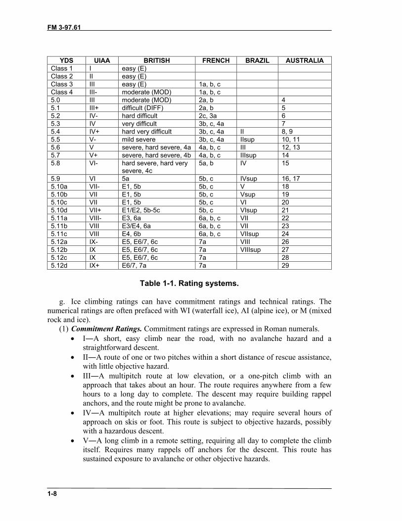
f. Climbing difficulties are rated by different systems. Table 1-1 shows acomparison of these systems.
• YDS (Yosemite Decimal System)―Used in the United States.• UIAA (Union des International Alpine Association)―Used in Europe.• British―The British use adjectives and numbers to designate the difficulty of
climbs. This system can be confusing if the climber is not familiar with it.• French―The French use numbers and letters to designate the difficulty of
climbs.• Brazilian―Brazil uses Roman Numerals and adjectives to designate
difficulty.• Australian―Australia uses only numbers to designate difficulty.
FM 3-97.61
1-8
YDS UIAA BRITISH FRENCH BRAZIL AUSTRALIAClass 1 I easy (E)Class 2 II easy (E)Class 3 III easy (E) 1a, b, cClass 4 III- moderate (MOD) 1a, b, c5.0 III moderate (MOD) 2a, b 45.1 III+ difficult (DIFF) 2a, b 55.2 IV- hard difficult 2c, 3a 65.3 IV very difficult 3b, c, 4a 75.4 IV+ hard very difficult 3b, c, 4a II 8, 95.5 V- mild severe 3b, c, 4a IIsup 10, 115.6 V severe, hard severe, 4a 4a, b, c III 12, 135.7 V+ severe, hard severe, 4b 4a, b, c IIIsup 145.8 VI- hard severe, hard very
severe, 4c5a, b IV 15
5.9 VI 5a 5b, c IVsup 16, 175.10a VII- E1, 5b 5b, c V 185.10b VII E1, 5b 5b, c Vsup 195.10c VII E1, 5b 5b, c VI 205.10d VII+ E1/E2, 5b-5c 5b, c VIsup 215.11a VIII- E3, 6a 6a, b, c VII 225.11b VIII E3/E4, 6a 6a, b, c VII 235.11c VIII E4, 6b 6a, b, c VIIsup 245.12a IX- E5, E6/7, 6c 7a VIII 265.12b IX E5, E6/7, 6c 7a VIIIsup 275.12c IX E5, E6/7, 6c 7a 285.12d IX+ E6/7, 7a 7a 29
Table 1-1. Rating systems.
g. Ice climbing ratings can have commitment ratings and technical ratings. Thenumerical ratings are often prefaced with WI (waterfall ice), AI (alpine ice), or M (mixedrock and ice).
(1) Commitment Ratings. Commitment ratings are expressed in Roman numerals.• I―A short, easy climb near the road, with no avalanche hazard and a
straightforward descent.• II―A route of one or two pitches within a short distance of rescue assistance,
with little objective hazard.• III―A multipitch route at low elevation, or a one-pitch climb with an
approach that takes about an hour. The route requires anywhere from a fewhours to a long day to complete. The descent may require building rappelanchors, and the route might be prone to avalanche.
• IV―A multipitch route at higher elevations; may require several hours ofapproach on skis or foot. This route is subject to objective hazards, possiblywith a hazardous descent.
• V―A long climb in a remote setting, requiring all day to complete the climbitself. Requires many rappels off anchors for the descent. This route hassustained exposure to avalanche or other objective hazards.
FM 3-97.61
1-9
• VI―A long ice climb in an alpine setting, with sustained technical climbing.Only elite climbers will complete it in a day. A difficult and involvedapproach and descent, with objective hazards ever-present, all in a remotearea.
• VII―Everything a grade VI has, and more of it. Possibly days to approach theclimb, and objective hazards rendering survival as questionable. Difficultphysically and mentally.
(2) Technical Ratings. Technical ratings are expressed as Arabic numerals.• 1―A frozen lake or stream bed.• 2―A pitch with short sections of ice up to 80 degrees; lots of opportunity for
protection and good anchors.• 3―Sustained ice up to 80 degrees; the ice is usually good, with places to rest,
but it requires skill at placing protection and setting anchors.• 4―A sustained pitch that is vertical or slightly less than vertical; may have
special features such as chandeliers and run-outs between protection.• 5―A long, strenuous pitch, possibly 50 meters of 85- to 90-degree ice with
few if any rests between anchors. The pitch may be shorter, but on featurelessice. Good skills at placing protection are required.
• 6―A full 50-meter pitch of dead vertical ice, possibly of poor quality;requires efficiency of movement and ability to place protection while inawkward stances.
• 7―A full rope length of thin vertical or overhanging ice of dubious adhesion.An extremely tough pitch, physically and mentally, requiring agility andcreativity.
• 8―Simply the hardest ice climbing ever done; extremely bold and gymnastic.
1-7. CROSS-COUNTRY MOVEMENTSoldiers must know the terrain to determine the feasible routes for cross-countrymovement when no roads or trails are available.
a. A pre-operations intelligence effort should include topographic and photographicmap coverage as well as detailed weather data for the area of operations. When planningmountain operations, additional information may be needed about size, location, andcharacteristics of landforms; drainage; types of rock and soil; and the density anddistribution of vegetation. Control must be decentralized to lower levels because ofvaried terrain, erratic weather, and communication problems inherent to mountainousregions.
b. Movement is often restricted due to terrain and weather. The erratic weatherrequires that soldiers be prepared for wide variations in temperature, types, and amountsof precipitation.
(1) Movement above the timberline reduces the amount of protective cover availableat lower elevations. The logistical problem is important; therefore, each man must beself-sufficient to cope with normal weather changes using materials from his rucksack.
(2) Movement during a storm is difficult due to poor visibility and bad footing onsteep terrain. Although the temperature is often higher during a storm than during clearweather, the dampness of rain and snow and the penetration of wind cause soldiers tochill quickly. Although climbers should get off the high ground and seek shelter and
FM 3-97.61
1-10
warmth, if possible, during severe mountain storms, capable commanders may usereduced visibility to achieve tactical surprise.
c. When the tactical situation requires continued movement during a storm, thefollowing precautions should be observed:
• Maintain visual contact.• Keep warm. Maintain energy and body heat by eating and drinking often;
carry food that can be eaten quickly and while on the move.• Keep dry. Wear wet-weather clothing when appropriate, but do not overdress,
which can cause excessive perspiration and dampen clothing. As soon as theobjective is reached and shelter secured, put on dry clothing.
• Do not rush. Hasty movement during storms leads to breaks in contact andaccidents.
• If lost, stay warm, dry, and calm.• Do not use ravines as routes of approach during a storm as they often fill with
water and are prone to flash floods.• Avoid high pinnacles and ridgelines during electrical storms.• Avoid areas of potential avalanche or rock-fall danger.
1-8. COVER AND CONCEALMENTWhen moving in the mountains, outcroppings, boulders, heavy vegetation, andintermediate terrain can provide cover and concealment. Digging fighting positions andtemporary fortifications is difficult because soil is often thin or stony. The selection ofdug-in positions requires detailed planning. Some rock types, such as volcanic tuff, areeasily excavated. In other areas, boulders and other loose rocks can be used for buildinghasty fortifications. In alpine environments, snow and ice blocks may be cut and stackedto supplement dug-in positions. As in all operations, positions and routes must becamouflaged to blend in with the surrounding terrain to prevent aerial detection.
1-9. OBSERVATIONObservation in mountains varies because of weather and ground cover. The dominatingheight of mountainous terrain permits excellent long-range observation. However, rapidlychanging weather with frequent periods of high winds, rain, snow, sleet, hail, and fog canlimit visibility. The rugged nature of the terrain often produces dead space at midranges.
a. Low cloud cover at higher elevations may neutralize the effectiveness of OPsestablished on peaks or mountaintops. High wind speeds and sound often mask the noisesof troop movement. Several OPs may need to be established laterally, in depth, and atvarying altitudes to provide visual coverage of the battle area.
b. Conversely, the nature of the terrain can be used to provide concealment fromobservation. This concealment can be obtained in the dead space. Mountainous regionsare subject to intense shadowing effects when the sun is low in relatively clear skies. Thecontrast from lighted to shaded areas causes visual acuity in the shaded regions to beconsiderably reduced. These shadowed areas can provide increased concealment whencombined with other camouflage and should be considered in maneuver plans.

FM 3-97.61
1-11
1-10. FIELDS OF FIREFields of fire, like observation, are excellent at long ranges. However, dead space is aproblem at short ranges. When forces cannot be positioned to cover dead space withdirect fires, mines and obstacles or indirect fire must be used. Range determination isdeceptive in mountainous terrain. Soldiers must routinely train in range estimation inmountainous regions to maintain their proficiency.
Section II. MOUNTAIN WEATHERMost people subconsciously “forecast” the weather. If they look outside and see darkclouds they may decide to take rain gear. If an unexpected wind strikes, people glance tothe sky for other bad signs. A conscious effort to follow weather changes will ultimatelylead to a more accurate forecast. An analysis of mountain weather and how it is affectedby mountain terrain shows that such weather is prone to patterns and is usually severe,but patterns are less obvious in mountainous terrain than in other areas. Conditionsgreatly change with altitude, latitude, and exposure to atmospheric winds and air masses.Mountain weather can be extremely erratic. It varies from stormy winds to calm, andfrom extreme cold to warmth within a short time or with a minor shift in locality. Theseverity and variance of the weather causes it to have a major impact on militaryoperations.
1-11. CONSIDERATIONS FOR PLANNINGMountain weather can be either a dangerous obstacle to operations or a valuable aid,depending on how well it is understood and to what extent advantage is taken of itspeculiar characteristics.
a. Weather often determines the success or failure of a mission since it is highlychangeable. Military operations plans must be flexible, especially in planning airmobileand airborne operations. The weather must be anticipated to allow enough time forplanning so that the leaders of subordinate units can use their initiative in turning animportant weather factor in their favor. The clouds that often cover the tops of mountainsand the fogs that cover valleys are an excellent means of concealing movements thatnormally are made during darkness or in smoke. Limited visibility can be used as acombat multiplier.
b. The safety or danger of almost all high mountain regions, especially in winter,depends upon a change of a few degrees of temperature above or below the freezingpoint. Ease and speed of travel depend mainly on the weather. Terrain that can be crossedswiftly and safely one day may become impassable or highly dangerous the next due tosnowfall, rainfall, or a rise in temperature. The reverse can happen just as quickly. Theprevalence of avalanches depends on terrain, snow conditions, and weather factors.
c. Some mountains, such as those found in desert regions, are dry and barren withtemperatures ranging from extreme heat in the summer to extreme cold in the winter. Intropical regions, lush jungles with heavy seasonal rains and little temperature variationoften cover mountains. High rocky crags with glaciated peaks can be found in mountainranges at most latitudes along the western portion of the Americas and Asia.
d. Severe weather may decrease morale and increase basic survival problems. Theseproblems can be minimized when men have been trained to accept the weather by being

FM 3-97.61
1-12
self-sufficient. Mountain soldiers properly equipped and trained can use the weather totheir advantage in combat operations.
1-12. MOUNTAIN AIRHigh mountain air is dry and may be drier in the winter. Cold air has a reduced capacityto hold water vapor. Because of this increased dryness, equipment does not rust asquickly and organic material decomposes slowly. The dry air also requires soldiers toincrease consumption of water. The reduced water vapor in the air causes an increase inevaporation of moisture from the skin and in loss of water through transpiration in therespiratory system. Due to the cold, most soldiers do not naturally consume the quantityof fluids they would at higher temperatures and must be encouraged to consciouslyincrease their fluid intake.
a. Pressure is low in mountainous areas due to the altitude. The barometer usuallydrops 2.5 centimeters for every 300 meters gained in elevation (3 percent).
b. The air at higher altitudes is thinner as atmospheric pressure drops with theincreasing altitude. The altitude has a natural filtering effect on the sun’s rays. Rays areabsorbed or reflected in part by the molecular content of the atmosphere. This effect isgreater at lower altitudes. At higher altitudes, the thinner, drier air has a reducedmolecular content and, consequently, a reduced filtering effect on the sun’s rays. Theintensity of both visible and ultraviolet rays is greater with increased altitude. Theseconditions increase the chance of sunburn, especially when combined with a snow coverthat reflects the rays upward.
1-13. WEATHER CHARACTERISTICSThe earth is surrounded by an atmosphere that is divided into several layers. The world’sweather systems are in the lower of these layers known as the “troposphere.” This layerreaches as high as 40,000 feet. Weather is a result of an atmosphere, oceans, land masses,unequal heating and cooling from the sun, and the earth’s rotation. The weather found inany one place depends on many things such as the air temperature, humidity (moisturecontent), air pressure (barometric pressure), how it is being moved, and if it is being liftedor not.
a. Air pressure is the “weight” of the atmosphere at any given place. The higher thepressure, the better the weather will be. With lower air pressure, the weather will morethan likely be worse. In order to understand this, imagine that the air in the atmosphereacts like a liquid. Areas with a high level of this “liquid” exert more pressure on an areaand are called high-pressure areas. Areas with a lower level are called low-pressure areas.The average air pressure at sea level is 29.92 inches of mercury (hg) or 1,013 millibars(mb). The higher in altitude, the lower the pressure.
(1) High Pressure. The characteristics of a high-pressure area are as follows:• The airflow is clockwise and out.• Otherwise known as an “anticyclone”.• Associated with clear skies.• Generally the winds will be mild.• Depicted as a blue “H” on weather maps.

FM 3-97.61
1-13
(2) Low Pressure. The characteristics of a low-pressure area are as follows:• The airflow is counterclockwise and in.• Otherwise known as a “cyclone”.• Associated with bad weather.• Depicted as a red “L” on weather maps.
b. Air from a high-pressure area is basically trying to flow out and equalize itspressure with the surrounding air. Low pressure, on the other hand, is building upvertically by pulling air in from outside itself, which causes atmospheric instabilityresulting in bad weather.
c. On a weather map, these differences in pressure are depicted as isobars. Isobarsresemble contour lines and are measured in either millibars or inches of mercury. Theareas of high pressure are called “ridges” and lows are called “troughs.”
1-14. WINDIn high mountains, the ridges and passes are seldom calm; however, strong winds inprotected valleys are rare. Normally, wind speed increases with altitude since the earth’sfrictional drag is strongest near the ground. This effect is intensified by mountainousterrain. Winds are accelerated when they converge through mountain passes and canyons.Because of these funneling effects, the wind may blast with great force on an exposedmountainside or summit. Usually, the local wind direction is controlled by topography.
a. The force exerted by wind quadruples each time the wind speed doubles; that is,wind blowing at 40 knots pushes four times harder than a wind blowing at 20 knots. Withincreasing wind strength, gusts become more important and may be 50 percent higherthan the average wind speed. When wind strength increases to a hurricane force of 64knots or more, soldiers should lay on the ground during gusts and continue movingduring lulls. If a hurricane- force wind blows where there is sand or snow, dense cloudsfill the air. The rocky debris or chunks of snow crust are hurled near the surface. Duringthe winter season, or at high altitudes, commanders must be constantly aware of thewind-chill factor and associated cold-weather injuries (see Chapter 2).
b. Winds are formed due to the uneven heating of the air by the sun and rotation ofthe earth. Much of the world’s weather depends on a system of winds that blow in a setdirection.
c. Above hot surfaces, air expands and moves to colder areas where it cools andbecomes denser, and sinks to the earth’s surface. The results are a circulation of air fromthe poles along the surface of the earth to the equator, where it rises and moves to thepoles again.
d. Heating and cooling together with the rotation of the earth causes surface winds.In the Northern Hemisphere, there are three prevailing winds:
(1) Polar Easterlies. These are winds from the polar region moving from the east.This is air that has cooled and settled at the poles.
(2) Prevailing Westerlies. These winds originate from approximately 30 degreesnorth latitude from the west. This is an area where prematurely cooled air, due to theearth’s rotation, has settled to the surface.
(3) Northeast Tradewinds. These are winds that originate from approximately 30o
north from the northeast.

FM 3-97.61
1-14
e. The jet stream is a long meandering current of high-speed winds often exceeding250 miles per hour near the transition zone between the troposphere and the stratosphereknown as the tropopause. These winds blow from a generally westerly direction dippingdown and picking up air masses from the tropical regions and going north and bringingdown air masses from the polar regions.
f. The patterns of wind mentioned above move air. This air comes in parcels called“air masses.” These air masses can vary from the size of a small town to as large as acountry. These air masses are named from where they originate:
• Maritime―over water.• Continental―over land• Polar―north of 60o north latitude.• Tropical―south of 60o north latitude.
Combining these parcels of air provides the names and description of the four types of airmasses:
• Continental Polar―cold, dry air mass.• Maritime Polar―cold, wet air mass.• Maritime Tropical―warm, wet air mass.• Continental Tropical―warm, dry air mass.
g. Two types of winds are peculiar to mountain environments, but do not necessarilyaffect the weather.
(1) Anabatic Wind (Valley Winds). These winds blow up mountain valleys to replacewarm rising air and are usually light winds.
(2) Katabatic Wind (Mountain Wind). These winds blow down mountain valleyslopes caused by the cooling of air and are occasionally strong winds.
1-15. HUMIDITYHumidity is the amount of moisture in the air. All air holds water vapor even if it cannotbe seen. Air can hold only so much water vapor; however, the warmer the air, the moremoisture it can hold. When air can hold all that it can the air is “saturated” or has 100percent relative humidity.
a. If air is cooled beyond its saturation point, the air will release its moisture in oneform or another (clouds, fog, dew, rain, snow, and so on). The temperature at which thishappens is called the “condensation point”. The condensation point varies depending onthe amount of water vapor contained in the air and the temperature of the air. If the aircontains a great deal of water, condensation can occur at a temperature of 68 degreesFahrenheit, but if the air is dry and does not hold much moisture, condensation may notform until the temperature drops to 32 degrees Fahrenheit or even below freezing.
b. The adiabatic lapse rate is the rate at which air cools as it rises or warms as itdescends. This rate varies depending on the moisture content of the air. Saturated (moist)air will warm and cool approximately 3.2 degrees Fahrenheit per 1,000 feet of elevationgained or lost. Dry air will warm and cool approximately 5.5 degrees Fahrenheit per1,000 feet of elevation gained or lost.
1-16. CLOUD FORMATIONClouds are indicators of weather conditions. By reading cloud shapes and patterns,observers can forecast weather with little need for additional equipment such as a

FM 3-97.61
1-15
barometer, wind meter, and thermometer. Any time air is lifted or cooled beyond itssaturation point (100 percent relative humidity), clouds are formed. The four ways airgets lifted and cooled beyond its saturation point are as follows.
a. Convective Lifting. This effect happens due to the sun’s heat radiating off theEarth’s surface causing air currents (thermals) to rise straight up and lift air to a point ofsaturation.
b. Frontal Lifting. A front is formed when two air masses of different moisturecontent and temperature collide. Since air masses will not mix, warmer air is forced aloftover the colder air mass. From there it is cooled and then reaches its saturation point.Frontal lifting creates the majority of precipitation.
c. Cyclonic Lifting. An area of low pressure pulls air into its center from all over ina counterclockwise direction. Once this air reaches the center of the low pressure, it hasnowhere to go but up. Air continues to lift until it reaches the saturation point.
d. Orographic Lifting. This happens when an air mass is pushed up and over amass of higher ground such as a mountain. Air is cooled due to the adiabatic lapse rateuntil the air’s saturation point is reached.
1-17. TYPES OF CLOUDSClouds are one of the signposts to what is happening with the weather. Clouds can bedescribed in many ways. They can be classified by height or appearance, or even by theamount of area covered vertically or horizontally. Clouds are classified into fivecategories: low-, mid-, and high-level clouds; vertically-developed clouds; and lesscommon clouds.
a. Low-Level Clouds. Low-level clouds (0 to 6,500 feet) are either cumulus orstratus (Figures 1-1 and 1-2, page 1-16). Low-level clouds are mostly composed of waterdroplets since their bases lie below 6,500 feet. When temperatures are cold enough, theseclouds may also contain ice particles and snow.
(1) The two types of precipitating low-level clouds are nimbostratus andstratocumulus (Figures 1-3 and 1-4, page 1-17).
(a) Nimbostratus clouds are dark, low-level clouds accompanied by light tomoderately falling precipitation. The sun or moon is not visible through nimbostratusclouds, which distinguishes them from mid-level altostratus clouds. Because of the fogand falling precipitation commonly found beneath and around nimbostratus clouds, thecloud base is typically extremely diffuse and difficult to accurately determine.
(b) Stratocumulus clouds generally appear as a low, lumpy layer of clouds that issometimes accompanied by weak precipitation. Stratocumulus vary in color from darkgray to light gray and may appear as rounded masses with breaks of clear sky in between.Because the individual elements of stratocumulus are larger than those of altocumulus,deciphering between the two cloud types is easier. With your arm extended toward thesky, altocumulus elements are about the size of a thumbnail while stratocumulus areabout the size of a fist.

FM 3-97.61
1-16
Figure 1-1. Cumulus clouds.
Figure 1-2. Stratus clouds.

FM 3-97.61
1-17
Figure 1-3. Nimbostratus clouds.
Figure 1-4. Stratocumulus clouds.
(2) Low-level clouds may be identified by their height above nearby surroundingrelief of known elevation. Most precipitation originates from low-level clouds becauserain or snow usually evaporate before reaching the ground from higher clouds. Low-levelclouds usually indicate impending precipitation, especially if the cloud is more than 3,000feet thick. (Clouds that appear dark at their bases are more than 3,000 feet thick.)
b. Mid-Level Clouds. Mid-level clouds (between 6,500 to 20,000 feet) have a prefixof alto. Middle clouds appear less distinct than low clouds because of their height. Altoclouds with sharp edges are warmer because they are composed mainly of water droplets.Cold clouds, composed mainly of ice crystals and usually colder than -30 degrees F, havedistinct edges that grade gradually into the surrounding sky. Middle clouds usually

FM 3-97.61
1-18
indicate fair weather, especially if they are rising over time. Lowering middle cloudsindicate potential storms, though usually hours away. There are two types of mid-levelclouds, altocumulus and altostratus clouds (Figures 1-5 and 1-6).
(1) Altocumulus clouds can appear as parallel bands or rounded masses. Typically aportion of an altocumulus cloud is shaded, a characteristic which makes themdistinguishable from high-level cirrocumulus. Altocumulus clouds usually form inadvance of a cold front. The presence of altocumulus clouds on a warm humid summermorning is commonly followed by thunderstorms later in the day. Altocumulus cloudsthat are scattered rather than even, in a blue sky, are called “fair weather” cumulus andsuggest arrival of high pressure and clear skies.
(2) Altostratus clouds are often confused with cirrostratus. The one distinguishingfeature is that a halo is not observed around the sun or moon. With altostratus, the sun ormoon is only vaguely visible and appears as if it were shining through frosted glass.
Figure 1-5. Altocumulus.
Figure 1-6. Altostratus.

FM 3-97.61
1-19
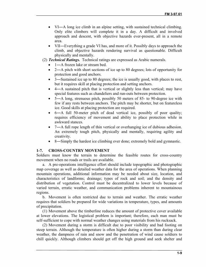
c. High-Level Clouds. High-level clouds (more than 20,000 feet above groundlevel) are usually frozen clouds, indicating air temperatures at that elevation below -30degrees Fahrenheit, with a fibrous structure and blurred outlines. The sky is often coveredwith a thin veil of cirrus that partly obscures the sun or, at night, produces a ring of lightaround the moon. The arrival of cirrus indicates moisture aloft and the approach of atraveling storm system. Precipitation is often 24 to 36 hours away. As the stormapproaches, the cirrus thickens and lowers, becoming altostratus and eventually stratus.Temperatures are warm, humidity rises, and winds become southerly or south easterly.The two types of high-level clouds are cirrus and cirrostratus (Figure 1-7 and Figure 1-8,page 1-20).
(1) Cirrus clouds are the most common of the high-level clouds. Typically found ataltitudes greater than 20,000 feet, cirrus are composed of ice crystals that form whensuper-cooled water droplets freeze. Cirrus clouds generally occur in fair weather andpoint in the direction of air movement at their elevation. Cirrus can be observed in avariety of shapes and sizes. They can be nearly straight, shaped like a comma, orseemingly all tangled together. Extensive cirrus clouds are associated with anapproaching warm front.
(2) Cirrostratus clouds are sheet-like, high-level clouds composed of ice crystals.They are relatively transparent and can cover the entire sky and be up to several thousandfeet thick. The sun or moon can be seen through cirrostratus. Sometimes the onlyindication of cirrostratus clouds is a halo around the sun or moon. Cirrostratus cloudstend to thicken as a warm front approaches, signifying an increased production of icecrystals. As a result, the halo gradually disappears and the sun or moon becomes lessvisible.
Figure 1-7. Cirrus.
FM 3-97.61
1-20
Figure 1-8. Cirrostratus.
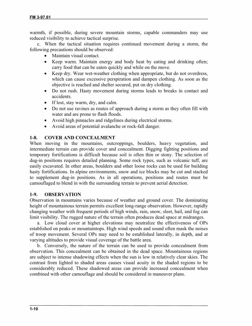
d. Vertical-Development Clouds. Clouds with vertical development can grow toheights in excess of 39,000 feet, releasing incredible amounts of energy. The two types ofclouds with vertical development are fair weather cumulus and cumulonimbus.
(1) Fair weather cumulus clouds have the appearance of floating cotton balls andhave a lifetime of 5 to 40 minutes. Known for their flat bases and distinct outlines, fairweather cumulus exhibit only slight vertical growth, with the cloud tops designating thelimit of the rising air. Given suitable conditions, however, these clouds can later developinto towering cumulonimbus clouds associated with powerful thunderstorms. Fairweather cumulus clouds are fueled by buoyant bubbles of air known as thermals that riseup from the earth’s surface. As the air rises, the water vapor cools and condenses formingwater droplets. Young fair weather cumulus clouds have sharply defined edges and baseswhile the edges of older clouds appear more ragged, an artifact of erosion. Evaporationalong the cloud edges cools the surrounding air, making it heavier and producing sinkingmotion outside the cloud. This downward motion inhibits further convection and growthof additional thermals from down below, which is why fair weather cumulus typicallyhave expanses of clear sky between them. Without a continued supply of rising air, thecloud begins to erode and eventually disappears.
(2) Cumulonimbus clouds are much larger and more vertically developed than fairweather cumulus (Figure 1-9). They can exist as individual towers or form a line oftowers called a squall line. Fueled by vigorous convective updrafts, the tops ofcumulonimbus clouds can reach 39,000 feet or higher. Lower levels of cumulonimbusclouds consist mostly of water droplets while at higher elevations, where thetemperatures are well below freezing, ice crystals dominate the composition. Underfavorable conditions, harmless fair weather cumulus clouds can quickly develop intolarge cumulonimbus associated with powerful thunderstorms known as super-cells.Super-cells are large thunderstorms with deep rotating updrafts and can have a lifetime ofseveral hours. Super-cells produce frequent lightning, large hail, damaging winds, and

FM 3-97.61
1-21
tornadoes. These storms tend to develop during the afternoon and early evening when theeffects of heating from the sun are the strongest.
Figure 1-9. Cumulonimbus.
e. Other Cloud Types. These clouds are a collection of miscellaneous types that donot fit into the previous four groups. They are orographic clouds, lenticulars, andcontrails.
(1) Orographic clouds develop in response to the forced lifting of air by the earth’stopography. Air passing over a mountain oscillates up and down as it moves downstream.Initially, stable air encounters a mountain, is lifted upward, and cools. If the air cools toits saturation temperature during this process, the water vapor condenses and becomesvisible as a cloud. Upon reaching the mountain top, the air is heavier than theenvironment and will sink down the other side, warming as it descends. Once the airreturns to its original height, it has the same buoyancy as the surrounding air. However,the air does not stop immediately because it still has momentum carrying it downward.With continued descent, the air becomes warmer then the surrounding air and acceleratesback upwards towards its original height. Another name for this type of cloud is thelenticular cloud.
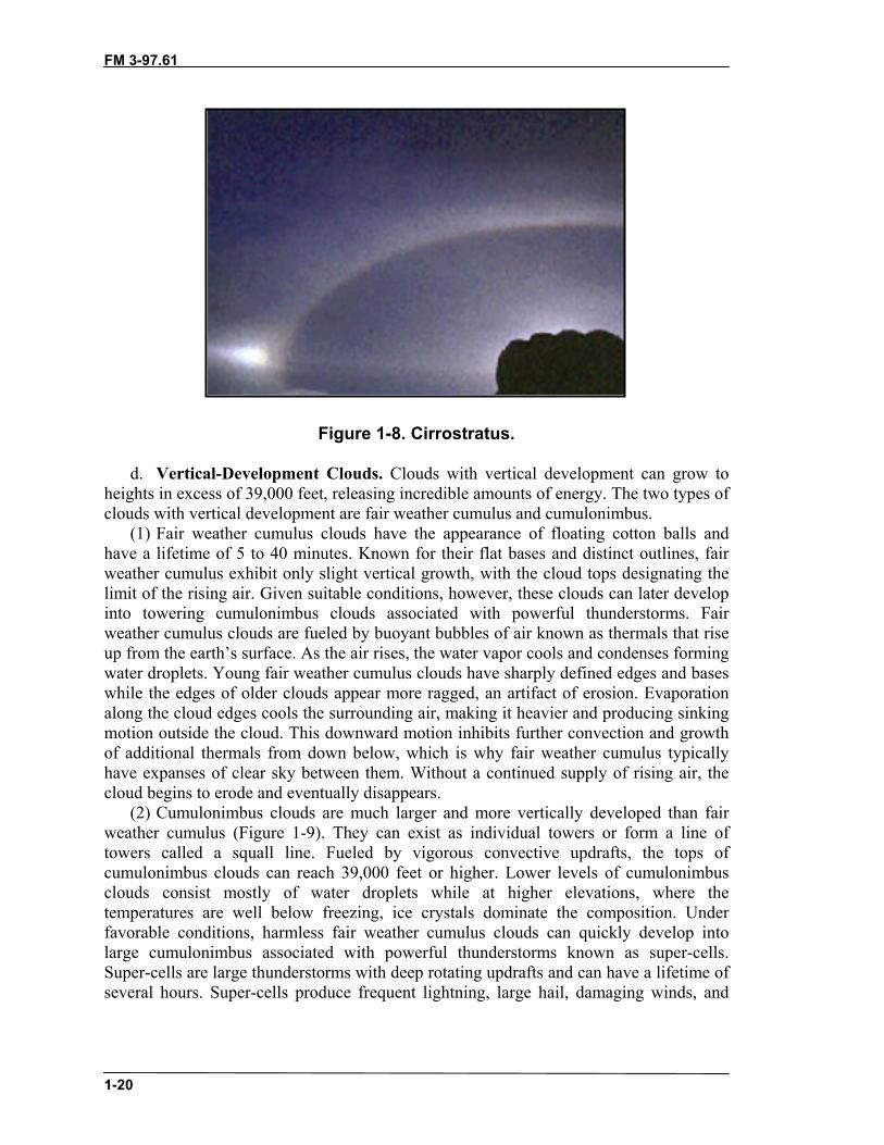
(2) Lenticular clouds are cloud caps that often form above pinnacles and peaks, andusually indicate higher winds aloft (Figure 1-10, page 1-22). Cloud caps with a lensshape, similar to a “flying saucer,” indicate extremely high winds (over 40 knots).Lenticulars should always be watched for changes. If they grow and descend, badweather can be expected.
FM 3-97.61
1-22
Figure 1-10. Lenticular.
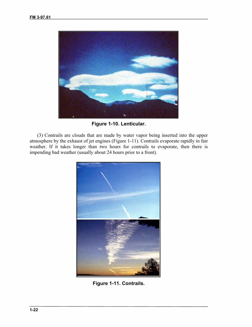
(3) Contrails are clouds that are made by water vapor being inserted into the upperatmosphere by the exhaust of jet engines (Figure 1-11). Contrails evaporate rapidly in fairweather. If it takes longer than two hours for contrails to evaporate, then there isimpending bad weather (usually about 24 hours prior to a front).
Figure 1-11. Contrails.

FM 3-97.61
1-23
f. Cloud Interpretation. Serious errors can occur in interpreting the extent of cloudcover, especially when cloud cover must be reported to another location. Cloud coveralways appears greater on or near the horizon, especially if the sky is covered withcumulus clouds, since the observer is looking more at the sides of the clouds rather thanbetween them. Cloud cover estimates should be restricted to sky areas more than 40degrees above the horizon―that is, to the local sky. Assess the sky by dividing the 360degrees of sky around you into eighths. Record the coverage in eighths and the types ofclouds observed.
1-18. FRONTSFronts occur when two air masses of different moisture and temperature contents meet.One of the indicators that a front is approaching is the progression of the clouds. The fourtypes of fronts are warm, cold, occluded, and stationary.
a. Warm Front. A warm front occurs when warm air moves into and over a sloweror stationary cold air mass. Because warm air is less dense, it will rise up and over thecooler air. The cloud types seen when a warm front approaches are cirrus, cirrostratus,nimbostratus (producing rain), and fog. Occasionally, cumulonimbus clouds will be seenduring the summer months.
b. Cold Front. A cold front occurs when a cold air mass overtakes a slower orstationary warm air mass. Cold air, being more dense than warm air, will force the warmair up. Clouds observed will be cirrus, cumulus, and then cumulonimbus producing ashort period of showers.
c. Occluded Front. Cold fronts generally move faster than warm fronts. The coldfronts eventually overtake warm fronts and the warm air becomes progressively liftedfrom the surface. The zone of division between cold air ahead and cold air behind iscalled a “cold occlusion.” If the air behind the front is warmer than the air ahead, it is awarm occlusion. Most land areas experience more occlusions than other types of fronts.The cloud progression observed will be cirrus, cirrostratus, altostratus, and nimbostratus.Precipitation can be from light to heavy.
d. Stationary Front. A stationary front is a zone with no significant air movement.When a warm or cold front stops moving, it becomes a stationary front. Once thisboundary begins forward motion, it once again becomes a warm or cold front. Whencrossing from one side of a stationary front to another, there is typically a noticeabletemperature change and shift in wind direction. The weather is usually clear to partlycloudy along the stationary front.
1-19. TEMPERATURENormally, a temperature drop of 3 to 5 degrees Fahrenheit for every 1,000 feet gain inaltitude is encountered in motionless air. For air moving up a mountain with condensationoccurring (clouds, fog, and precipitation), the temperature of the air drops 3.2 degreesFahrenheit with every 1,000 feet of elevation gain. For air moving up a mountain with noclouds forming, the temperature of the air drops 5.5 degrees Fahrenheit for every 1,000feet of elevation gain.
a. An expedient to this often occurs on cold, clear, calm mornings. During a troopmovement or climb started in a valley, higher temperatures may often be encountered asaltitude is gained. This reversal of the normal cooling with elevation is called temperature
FM 3-97.61
1-24
inversion. Temperature inversions are caused when mountain air is cooled by ice, snow,and heat loss through thermal radiation. This cooler, denser air settles into the valleys andlow areas. The inversion continues until the sun warms the surface of the earth or amoderate wind causes a mixing of the warm and cold layers. Temperature inversions arecommon in the mountainous regions of the arctic, subarctic, and mid-latitudes.
b. At high altitudes, solar heating is responsible for the greatest temperaturecontrasts. More sunshine and solar heat are received above the clouds than below. Theimportant effect of altitude is that the sun’s rays pass through less of the atmosphere andmore direct heat is received than at lower levels, where solar radiation is absorbed andreflected by dust and water vapor. Differences of 40 to 50 degrees Fahrenheit may occurbetween surface temperatures in the shade and surface temperatures in the sun. This isparticularly true for dark metallic objects. The difference in temperature felt on the skinbetween the sun and shade is normally 7 degrees Fahrenheit. Special care must be takento avoid sunburn and snow blindness. Besides permitting rapid heating, the clear air athigh altitudes also favors rapid cooling at night. Consequently, the temperature rises fastafter sunrise and drops quickly after sunset. Much of the chilled air drains downward, dueto convection currents, so that the differences between day and night temperatures aregreater in valleys than on slopes.
c. Local weather patterns force air currents up and over mountaintops. Air is cooledon the windward side of the mountain as it gains altitude, but more slowly (3.2 degreesFahrenheit per 1,000 feet) if clouds are forming due to heat release when water vaporbecomes liquid. On the leeward side of the mountain, this heat gained from thecondensation on the windward side is added to the normal heating that occurs as the airdescends and air pressure increases. Therefore, air and winds on the leeward slope areconsiderably warmer than on the windward slope, which is referred to as Chinook winds.The heating and cooling of the air affects planning considerations primarily with regardto the clothing and equipment needed for an operation.
1-20. WEATHER FORECASTINGThe use of a portable aneroid barometer, thermometer, wind meter, and hygrometer helpin making local weather forecasts. Reports from other localities and from any weatherservice, including USAF, USN, or the National Weather Bureau, are also helpful.Weather reports should be used in conjunction with the locally observed current weathersituation to forecast future weather patterns.
a. Weather at various elevations may be quite different because cloud height,temperature, and barometric pressure will all be different. There may be overcast and rainin a lower area, with mountains rising above the low overcast into warmer clear weather.
b. To be effective, a forecast must reach the small-unit leaders who are expected toutilize weather conditions for assigned missions. Several different methods can be used tocreate a forecast. The method a forecaster chooses depends upon the forecaster’sexperience, the amount of data available, the level of difficulty that the forecast situationpresents, and the degree of accuracy needed to make the forecast. The five ways toforecast weather are:
(1) Persistence Method. “Today equals tomorrow” is the simplest way of producing aforecast. This method assumes that the conditions at the time of the forecast will not

FM 3-97.61
1-25
change; for example, if today was hot and dry, the persistence method predicts thattomorrow will be the same.
(2) Trends Method. “Nowcasting” involves determining the speed and direction offronts, high- and low-pressure centers, and clouds and precipitation. For example, if acold front moves 300 miles during a 24-hour period, we can predict that it will travel 300miles in another 24-hours.
(3) Climatology Method. This method averages weather statistics accumulated overmany years. This only works well when the pattern is similar to the following years.
(4) Analog Method. This method examines a day’s forecast and recalls a day in thepast when the weather looked similar (an analogy). This method is difficult to usebecause finding a perfect analogy is difficult.
(5) Numerical Weather Prediction. This method uses computers to analyze allweather conditions and is the most accurate of the five methods.
1-21. RECORDING DATAAn accurate observation is essential in noting trends in weather patterns. Ideally, underchanging conditions, trends will be noted in some weather parameters. However, thismay not always be the case. A minor shift in the winds may signal an approaching storm.
a. Wind Direction. Assess wind direction as a magnetic direction from which thewind is blowing.
b. Wind Speed. Assess wind speed in knots.(1) If an anemometer is available, assess speed to the nearest knot.(2) If no anemometer is available, estimate the speed in knots. Judge the wind speed
by the way objects, such as trees, bushes, tents, and so forth, are blowing.c. Visibility in Meters. Observe the farthest visible major terrain or man-made
feature and determine the distance using any available map.d. Present Weather. Include any precipitation or obscuring weather. The following
are examples of present weather:• Rain―continuous and steady liquid precipitation that will last at least one
hour.• Rain showers―short-term and potentially heavy downpours that rarely last
more than one hour.• Snow―continuous and steady frozen precipitation that will last at least one
hour.• Snow showers―short-term and potentially heavy frozen downpours that
rarely last more than one hour.• Fog, haze―obstructs visibility of ground objects.• Thunderstorms―a potentially dangerous storm. Thunderstorms will produce
lightning, heavy downpours, colder temperatures, tornadoes (not toofrequently), hail, and strong gusty winds at the surface and aloft. Windscommonly exceed 35 knots.
e. Total Cloud Cover. Assess total cloud cover in eighths. Divide the sky into eightdifferent sections measuring from horizon to horizon. Count the sections with cloudcover, which gives the total cloud cover in eighths. (For example, if half of the sectionsare covered with clouds, total cloud cover is 4/8.)

FM 3-97.61
1-26
f. Ceiling Height. Estimate where the cloud base intersects elevated terrain. Note ifbases are above all terrain. If clouds are not touching terrain, then estimate to the best ofyour ability.
g. Temperature. Assess temperature with or without a thermometer.(1) With a thermometer, assess temperature in degrees Celsius (use Fahrenheit only if
Celsius conversion is not available). To convert Fahrenheit to Celsius: C = F minus 32times .55. To convert Celsius to Fahrenheit: F = 1.8 times C plus 32.
Example: 41 degrees F – 32 x .55 = 5 degrees C.5 degrees C x 1.8 + 32 = 41 degrees F.
(2) Without a thermometer, estimate temperature as above or below freezing (0oC), aswell as an estimated temperature.
h. Pressure Trend. With a barometer or altimeter, assess the pressure trend.(1) A high pressure moving in will cause altimeters to indicate lower elevation.(2) A low pressure moving in will cause altimeters to indicate higher elevation.i. Observed Weather. Note changes or trends in observed weather conditions.(1) Deteriorating trends include:
• Marked wind direction shifts. A high pressure system wind flows clockwise.A low pressure system wind flows counterclockwise. The closer the isometriclines are, the greater the differential of pressure (greater wind speeds).
• Marked wind speed increases.• Changes in obstructions to visibility.• Increasing cloud coverage.• Increase in precipitation. A steady drizzle is usually a long-lasting rain.• Lowering cloud ceilings.• Marked cooler temperature changes, which could indicate that a cold front is
passing through.• Marked increase in humidity.• Decreasing barometric pressure, which indicates a lower pressure system is
moving through the area.(2) Improving trends include:
• Steady wind direction, which indicates no change in weather systems in thearea.
• Decreasing wind speeds.• Clearing of obstructions to visibility.• Decreasing or ending precipitation.• Decreasing cloud coverage.• Increasing height of cloud ceilings.• Temperature changes slowly warmer.• Humidity decreases.• Increasing barometric pressure, which indicates that a higher pressure system
is moving through the area.j. Update. Continue to evaluate observed conditions and update the forecast.
FM 3-97.61
1-27
Section III. MOUNTAIN HAZARDSHazards can be termed natural (caused by natural occurrence), man-made (caused by anindividual, such as lack of preparation, carelessness, improper diet, equipment misuse), oras a combination (human trigger). There are two kinds of hazards while in themountains―subjective and objective. Combinations of objective and subjective hazardsare referred to as cumulative hazards.
1-22. SUBJECTIVE HAZARDSSubjective hazards are created by humans; for example, choice of route, companions,overexertion, dehydration, climbing above one’s ability, and poor judgment.
a. Falling. Falling can be caused by carelessness, over-fatigue, heavy equipment,bad weather, overestimating ability, a hold breaking away, or other reasons.
b. Bivouac Site. Bivouac sites must be protected from rockfall, wind, lightning,avalanche run-out zones, and flooding (especially in gullies). If the possibility of fallingexists, rope in, the tent and all equipment may have to be tied down.
c. Equipment. Ropes are not total security; they can be cut on a sharp edge or breakdue to poor maintenance, age, or excessive use. You should always pack emergency andbivouac equipment even if the weather situation, tour, or a short climb is seemingly lowof dangers.
1-23. OBJECTIVE HAZARDSObjective hazards are caused by the mountain and weather and cannot be influenced byman; for example, storms, rockfalls, icefalls, lightning, and so on.
a. Altitude. At high altitudes (especially over 6,500 feet), endurance andconcentration is reduced. Cut down on smoking and alcohol. Sleep well, acclimatizeslowly, stay hydrated, and be aware of signs and symptoms of high-altitude illnesses.Storms can form quickly and lightning can be severe.
b. Visibility. Fog, rain, darkness, and or blowing snow can lead to disorientation.Take note of your exact position and plan your route to safety before visibility decreases.Cold combined with fog can cause a thin sheet of ice to form on rocks (verglas).Whiteout conditions can be extremely dangerous. If you must move under theseconditions, it is best to rope up. Have the point man move to the end of the rope. Thesecond man will use the first man as an aiming point with the compass. Use a routesketch and march table. If the tactical situation does not require it, plan route so as not toget caught by darkness.
c. Gullies. Rock, snow, and debris are channeled down gullies. If ice is in the gully,climbing at night may be better because the warming of the sun will loosen stones andcause rockfalls.
d. Rockfall. Blocks and scree at the base of a climb can indicate recurring rockfall.Light colored spots on the wall may indicate impact chips of falling rock. Spring melt orwarming by the sun of the rock/ice/snow causes rockfall.
e. Avalanches. Avalanches are caused by the weight of the snow overloading theslope. (Refer to paragraph 1-25 for more detailed information on avalanches.)
f. Hanging Glaciers and Seracs. Avoid, if at all possible, hanging glaciers andseracs. They will fall without warning regardless of the time of day or time of year. One

FM 3-97.61
1-28
cubic meter of glacier ice weighs 910 kilograms (about 2,000 pounds). If you must crossthese danger areas, do so quickly and keep an interval between each person.
g. Crevasses. Crevasses are formed when a glacier flows over a slope and makes abend, or when a glacier separates from the rock walls that enclose it. A slope of only twoto three degrees is enough to form a crevasse. As this slope increases from 25 to 30degrees, hazardous icefalls can be formed. Likewise, as a glacier makes a bend, it islikely that crevasses will form at the outside of the bend. Therefore, the safest route on aglacier would be to the inside of bends, and away from steep slopes and icefalls. Extremecare must be taken when moving off of or onto the glacier because of the moat that ismost likely to be present.
1-24. WEATHER HAZARDSWeather conditions in the mountains may vary from one location to another as little as 10kilometers apart. Approaching storms may be hard to spot if masked by local peaks. Aclear, sunny day in July could turn into a snowstorm in less than an hour. Always packsome sort of emergency gear.
a. Winds are stronger and more variable in the mountains; as wind doubles in speed,the force quadruples.
b. Precipitation occurs more on the windward side than the leeward side of ranges.This causes more frequent and denser fog on the windward slope.
c. Above approximately 8,000 feet, snow can be expected any time of year in thetemperate climates.
d. Air is dryer at higher altitudes, so equipment does not rust as quickly, butdehydration is of greater concern.
e. Lightning is frequent, violent, and normally attracted to high points andprominent features in mountain storms. Signs indicative of thunderstorms are tingling ofthe skin, hair standing on end, humming of metal objects, crackling, and a bluish light(St. Elmo’s fire) on especially prominent metal objects (summit crosses and radiotowers).
(1) Avoid peaks, ridges, rock walls, isolated trees, fixed wire installations, cracks thatguide water, cracks filled with earth, shallow depressions, shallow overhangs, and rockneedles. Seek shelter around dry, clean rock without cracks; in scree fields; or in deepindentations (depressions, caves). Keep at least half a body’s length away from a cavewall and opening.
(2) Assume a one-point-of-contact body position. Squat on your haunches or sit on arucksack or rope. Pull your knees to your chest and keep both feet together. If half wayup the rock face, secure yourself with more than one point―lightning can burn throughrope. If already rappelling, touch the wall with both feet together and hurry to the nextanchor.
f. During and after rain, expect slippery rock and terrain in general and adjustmovement accordingly. Expect flash floods in gullies or chimneys. A climber can bewashed away or even drowned if caught in a gully during a rainstorm. Be especially alertfor falling objects that the rain has loosened.
g. Dangers from impending high winds include frostbite (from increased wind-chillfactor), windburn, being blown about (especially while rappelling), and debris being

FM 3-97.61
1-29
blown about. Wear protective clothing and plan the route to be finished before badweather arrives.
h. For each 100-meter rise in altitude, the temperature drops approximately onedegree Fahrenheit. This can cause hypothermia and frostbite even in summer, especiallywhen combined with wind, rain, and snow. Always wear or pack appropriate clothing.
i. If it is snowing, gullies may contain avalanches or snow sloughs, which may burythe trail. Snowshoes or skis may be needed in autumn or even late spring. Unexpectedsnowstorms may occur in the summer with accumulations of 12 to 18 inches; however,the snow quickly melts.
j. Higher altitudes provide less filtering effects, which leads to greater ultraviolet(UV) radiation intensity. Cool winds at higher altitudes may mislead one intounderestimating the sun’s intensity, which can lead to sunburns and other heat injuries.Use sunscreen and wear hat and sunglasses, even if overcast. Drink plenty of fluids.
1-25. AVALANCHE HAZARDSAvalanches occur when the weight of accumulated snow on a slope exceeds the cohesiveforces that hold the snow in place. (Table 1-2, page 1-32, shows an avalanche hazardevaluation checklist.)
a. Slope Stability. Slope stability is the key factor in determining the avalanchedanger.
(1) Slope Angle. Slopes as gentle as 15 degrees have avalanched. Most avalanchesoccur on slopes between 30 and 45 degrees. Slopes above 60 degrees often do not buildup significant quantities of snow because they are too steep.
(2) Slope Profile. Dangerous slab avalanches are more likely to occur on convexslopes, but may occur on concave slopes.
(3) Slope Aspect. Snow on north facing slopes is more likely to slide in midwinter.South facing slopes are most dangerous in the spring and on sunny, warm days. Slopes onthe windward side are generally more stable than leeward slopes.
(4) Ground Cover. Rough terrain is more stable than smooth terrain. On grassyslopes or scree, the snow pack has little to anchor to.
b. Triggers. Various factors trigger avalanches.(1) Temperature. When the temperature is extremely low, settlement and adhesion
occur slowly. Avalanches that occur during extreme cold weather usually occur during orimmediately following a storm. At a temperature just below freezing, the snowpackstabilizes quickly. At temperatures above freezing, especially if temperatures risequickly, the potential for avalanche is high. Storms with a rise in temperature can depositdry snow early, which bonds poorly with the heavier snow deposited later. Mostavalanches occur during the warmer midday.
(2) Precipitation. About 90 percent of avalanches occur during or within twenty-fourhours after a snowstorm. The rate at which snow falls is important. High rates of snowfall(2.5 centimeters per hour or greater), especially when accompanied by wind, are usuallyresponsible for major periods of avalanche activity. Rain falling on snow will increase itsweight and weakens the snowpack.
(3) Wind. Sustained winds of 15 miles per hour and over transport snow and formwind slabs on the lee side of slopes.
(4) Weight. Most victims trigger the avalanches that kill them.
FM 3-97.61
1-30
(5) Vibration. Passing helicopters, heavy equipment, explosions, and earth tremorshave triggered avalanches.
c. Snow Pits. Snow pits can be used to determine slope stability.(1) Dig the snow pit on the suspect slope or a slope with the same sun and wind
conditions. Snow deposits may vary greatly within a few meters due to wind and sunvariations. (On at least one occasion, a snow pit dug across the fall line triggered thesuspect slope). Dig a 2-meter by 2-meter pit across the fall line, through all the snow, tothe ground. Once the pit is complete, smooth the face with a shovel.
(2) Conduct a shovel shear test.(a) A shovel shear test puts pressure on a representative sample of the snowpack. The
core of this test is to isolate a column of the snowpack from three sides. The columnshould be of similar size to the blade of the shovel. Dig out the sides of the columnwithout pressing against the column with the shovel (this affects the strength). To isolatethe rear of the column, use a rope or string to saw from side to side to the base of thecolumn.
(b) If the column remained standing while cutting the rear, place the shovel facedown on the top of the column. Tap with varying degrees of strength on the shovel to seewhat force it takes to create movement on the bed of the column. The surface thateventually slides will be the layer to look at closer. This test provides a betterunderstanding of the snowpack strength. For greater results you will need to do this testin many areas and formulate a scale for the varying methods of tapping the shovel.
(3) Conduct a Rutschblock test. To conduct the test, isolate a column slightly longerthan the length of your snowshoes or skis (same method as for the shovel shear test). Oneperson moves on their skis or snowshoes above the block without disturbing the block.Once above, the person carefully places one showshoe or ski onto the block with no bodyweight for the first stage of the test. The next stage is adding weight to the first leg. Next,place the other foot on the block. If the block is still holding up, squat once, then twice,and so on. The remaining stage is to jump up and land on the block.
d. Types of Snow Avalanches. There are two types of snow avalanches: loose snow(point) and slab.
(1) Loose snow avalanches start at one point on the snow cover and grow in the shapeof an inverted “V.” Although they happen most frequently during the winter snowseason, they can occur at any time of the year in the mountains. They often fall as manysmall sluffs during or shortly after a storm. This process removes snow from steep upperslopes and either stabilizes lower slopes or loads them with additional snow.
(2) Wet loose snow avalanches occur in spring and summer in all mountain ranges.Large avalanches of this type, lubricated and weighed down by meltwater or rain cantravel long distances and have tremendous destructive power. Coastal ranges that havehigh temperatures and frequent rain are the most common areas for this type ofavalanche.
(3) Slab avalanches occur when cohesive snow begins to slide on a weak layer. Thefracture line where the moving snow breaks away from the snowpack makes this type ofavalanche easy to identify. Slab release is rapid. Although any avalanche can kill you,slab avalanches are generally considered more dangerous than loose snow avalanches.

FM 3-97.61
1-31
(a) Most slab avalanches occur during or shortly after a storm when slopes are loadedwith new snow at a critical rate. The old rule of never travel in avalanche terrain for a fewdays after a storm still holds true.
(b) As slabs become harder, their behavior becomes more unpredictable; they mayallow several people to ski across before releasing. Many experts believe they aresusceptible to rapid temperature changes. Packed snow expands and contracts withtemperature changes. For normal density, settled snow, a drop in temperature of 10degrees Celsius (18 degrees Fahrenheit) would cause a snow slope 300 meters wide tocontract 2 centimeters. Early ski mountaineers in the Alps noticed that avalanchessometimes occurred when shadows struck a previously sun-warmed slope.
d. Protective Measures. Avoiding known or suspected avalanche areas is theeasiest method of protection. Other measures include:
(1) Personal Safety. Remove your hands from ski pole wrist straps. Detach skirunaway cords. Prepare to discard equipment. Put your hood on. Close up your clothingto prepare for hypothermia. Deploy avalanche cord. Make avalanche probes and shovelsaccessible. Keep your pack on at all times—do not discard. Your pack can act as aflotation device, as well as protect your spine.
(2) Group Safety. Send one person across the suspect slope at a time with the rest ofthe group watching. All members of the group should move in the same track from safezone to safe zone.
e. Route Selection. Selecting the correct route will help avoid avalanche proneareas, which is always the best choice. Always allow a wide margin of safety whenmaking your decision.
(1) The safest routes are on ridge tops, slightly on the windward side; the next safestroute is out in the valley, far from the bottom of slopes.
(2) Avoid cornices from above or below. Should you encounter a dangerous slope,either climb to the top of the slope or descend to the bottom—well out of the way of therun-out zone. If you must traverse, pick a line where you can traverse downhill as quicklyas possible. When you must ascend a dangerous slope, climb to the side of the avalanchepath, and not directly up the center.
(3) Take advantage of dense timber, ridges, or rocky outcrops as islands of safety.Use them for lunch and rest stops. Spend as little time as possible on open slopes.
(4) Since most avalanches occur within twenty-four hours of a storm and or atmidday, avoid moving during these periods. Moving at night is tactically sound and maybe safer.
f. Stability Analysis. Look for nature’s billboards on slopes similar to the one youare on.
(1) Evidence of Avalanching. Look for recent avalanches and for signs of wind-loading and wind-slabs.
(2) Fracture Lines. Avoid any slopes showing cracks.(3) Sounds. Beware of hollow sounds—a “whumping” noise. They may suggest a
radical settling of the snowpack. g. Survival. People trigger avalanches that bury people. If these people recognized
the hazard and chose a different route, they would avoid the avalanche. The followingsteps should be followed if caught in an avalanche.

FM 3-97.61
1-32
(1) Discard equipment. Equipment can injure or burden you; discarded equipmentwill indicate your position to rescuers.
(2) Swim or roll to stay on tope of the snow. FIGHT FOR YOUR LIFE. Work towardthe edge of the avalanche. If you feel your feet touch the ground, give a hard push and tryto “pop out” onto the surface.
(3) If your head goes under the snow, shut your mouth, hold your breath, and positionyour hands and arms to form an air pocket in front of your face. Many avalanche victimssuffocate by having their mouths and noses plugged with snow.
(4) When you sense the slowing of the avalanche, you must try your hardest to reachthe surface. Several victims have been found quickly because a hand or foot was stickingabove the surface.
(5) When the snow comes to rest it sets up like cement and even if you are onlypartially buried, it may be impossible to dig yourself out. Don’t shout unless you hearrescuers immediately above you; in snow, no one can hear you scream. Don’t struggle tofree yourself—you will only waste energy and oxygen.
(6) Try to relax. If you feel yourself about to pass out, do not fight it. The respirationof an unconscious person is more shallow, their pulse rate declines, and the bodytemperature is lowered, all of which reduce the amount of oxygen needed. (See AppendixC for information on search and rescue techniques.)
Table 1-2. Avalanche hazard evaluation checklist.
FM 3-97.61(TC 90-6-1)
2-1
CHAPTER 2MOUNTAIN LIVING
Units deploying to high elevations must receive advanced training to survivein the harsh mountain environment. Normal activities (navigation,communications, and movement) require specialized techniques. Trainingshould be conducted as realistically as possible, preferably under severeconditions so the soldier gains confidence. Extended training exercises testsupport facilities and expose the soldier to the isolation common to mountainoperations. Training should reflect the harsh mountain environment andshould consider the following:
• Temperature and altitude extremes.• Hygiene and sanitation.• Limited living space (difficulty of bivouac).• Clothing requirements.
Section I. SURVIVALThe soldier trained to fight and survive in a mountain environment will have increasedconfidence in himself. Training should include: psychological preparation, locating water,shelter considerations, fire building, health hazards, and techniques for obtaining food (seeFM 21-76).
2-1. WATER SUPPLYMountain water should never be assumed safe for consumption. Training in water disciplineshould be emphasized to ensure soldiers drink water only from approved sources. Fluids lostthrough respiration, perspiration, and urination must be replaced if the soldier is to operateefficiently.
a. Maintaining fluid balance is a major problem in mountain operations. The sense ofthirst may be dulled by high elevations despite the greater threat of dehydration.Hyperventilation and the cool, dry atmosphere bring about a three- to four-fold increase inwater loss by evaporation through the lungs. Hard work and overheating increase theperspiration rate. The soldier must make an effort to drink liquids even when he does notfeel thirsty. One quart of water, or the equivalent, should be drunk every four hours; moreshould be drunk if the unit is conducting rigorous physical activity.
b. Three to six quarts of water each day should be consumed. About 75 percent of thehuman body is liquid. All chemical activities in the body occur in water solution, whichassists in removing toxic wastes and in maintaining an even body temperature. A loss of twoquarts of body fluid (2.5 percent of body weight) decreases physical efficiency by 25percent, and a loss of 12 quarts (15 percent of body weight) is usually fatal. Salt lost bysweating should be replaced in meals to avoid a deficiency and subsequent cramping.Consuming the usual military rations (three meals a day) provides sufficient sodiumreplacement. Salt tablets are not necessary and may contribute to dehydration.
c. Even when water is plentiful, thirst should be satisfied in increments. Quicklydrinking a large volume of water may actually slow the soldier. If he is hot and the water iscold, severe cramping may result. A basic rule is to drink small amounts often. Pure water

FM 3-97.61
2-2
should always be kept in reserve for first aid use. Emphasis must be placed on the three rulesof water discipline:
• Drink only treated water.• Conserve water for drinking. Potable water in the mountains may be in short
supply.• Do not contaminate or pollute water sources.
d. Snow, mountain streams, springs, rain, and lakes provide good sources of watersupply. Purification must be accomplished, however, no matter how clear the snow or waterappears. Fruits, juices, and powdered beverages may supplement and encourage waterintake (do not add these until the water has been treated since the purification tablets maynot work). Soldiers cannot adjust permanently to a decreased water intake. If the watersupply is insufficient, physical activity must be reduced. Any temporary deficiency shouldbe replaced to maintain maximum performance.
e. All water that is to be consumed must be potable. Drinking water must be taken onlyfrom approved sources or purified to avoid disease or the possible use of polluted water.Melting snow into water requires an increased amount of fuel and should be plannedaccordingly. Nonpotable water must not be mistaken for drinking water. Water that is unfitto drink, but otherwise not dangerous, may be used for other purposes such as bathing.Soldiers must be trained to avoid wasting water. External cooling (pouring water over thehead and chest) is a waste of water and an inefficient means of cooling. Drinking wateroften is the best way to maintain a cool and functioning body.
f. Water is scarce above the timberline. After setting up a perimeter (patrol base,assembly area, defense), a watering party should be employed. After sundown, highmountain areas freeze, and snow and ice may be available for melting to provide water. Inareas where water trickles off rocks, a shallow reservoir may be dug to collect water (afterthe sediment settles). Water should be treated with purification tablets (iodine tablets orcalcium hypochlorite), or by boiling at least one to two minutes. Filtering with commercialwater purification pumps can also be conducted. Solar stills may be erected if time andsunlight conditions permit (see FM 21-76). Water should be protected from freezing bystoring it next to a soldier or by placing it in a sleeping bag at night. Water should becollected at midday when the sun thaw available.
2-2. NUTRITIONSuccess in mountain operations depends on proper nutrition. Because higher altitudes affecteating habits, precautions must be taken. If possible, at least one hot meal each day shouldbe eaten, which may require personnel to heat their individual rations.
a. The following elements are characteristic of nutritional acclimatization in mountainoperations:
• Weight loss during the first two to three days at high elevation.• A loss of appetite with symptoms of mountain sickness.• Loss of weight usually stops with acclimatization.• At progressively higher elevations (greater than 14,000 feet), the tolerance of
fatty/high-protein foods rapidly decreases. A high carbohydrate diet may lessenthe symptoms of acute mountain sickness and is digested better than fat at highaltitudes.

FM 3-97.61
2-3
b. Increased fatigue may cause soldiers to become disinterested in eating properly.Decreased consumption may result in malnutrition because of the unpleasant taste of coldrations. Leaders should ensure that fuel tablets and squad stoves are available, or that naturalflammable materials are used if possible. Although there is no physiological need for hotfood, it does increase morale and a sense of well being. Loss of weight in the first few daysoccurs because of dehydration, metabolic changes, and loss of appetite. Carbohydrate-containing beverages, such as fruit juices and sports drinks, are an effective means ofincreasing carbohydrates, energy, and liquid intake when the normal appetite response isblunted at altitude.
c. Three major food components are required to maintain a well-functioning body:proteins, fats, and carbohydrates. These food components provide energy, amino acids,vitamins, fiber, and minerals. All three components must be provided in the correctproportions to maintain a healthy body.
(1) Protein. Proteins consist of a large number of amino acid units that are linkedtogether to form the protein. The amino acids, resulting from digestion of protein, areabsorbed through the intestine into the blood, and are used to make or replace body proteins(muscle and body tissue). Sources of readily useable animal proteins include eggs, milk,cheese, poultry, fish, and meats. Other foods such as cereals, vegetables, and legumes alsoprovide amino acids. These proteins are not as balanced in essential amino acid compositionas meat, eggs, or milk proteins. The minimum daily protein requirement, regardless ofphysical activity, is 8 ounces for a 154-pound man. Since amino acids are either oxidized forenergy or stored as fats, consuming excess protein is inefficient and may increase the waterintake needed for urea nitrogen excretion. Protein requires water for digestion and mayfacilitate dehydration. Proteins provide the body about four kilocalories of energy per gramand require the most energy for the body to digest.
(2) Fats. Fats are the most concentrated form of food energy. Of the total daily caloricintake, 25 to 30 percent may be supplied as fats. Main sources of fats are meats, nuts, butter,eggs, milk, and cheese. Fats require more water and oxygen, and are harder to digest athigher altitudes. Fats are the body’s natural stored source of energy. Fats provide the bodyaround 9 kilocalories of energy per gram and require less energy for the body to digest thanprotein but more than carbohydrates.
(3) Carbohydrates. Carbohydrates are an important source of calories. In the form ofglucose, carbohydrates are found in the most important energy-producing cycles in thebody’s cells. If carbohydrate intake exceeds energy needs, moderate amounts are stored inthe muscles and liver. Larger amounts are converted into fats and stored in that form.Carbohydrates should compose up to 50 percent of the total daily caloric intake.Nutritionally, the most useful sources of carbohydrates are foods such as unrefined grains,vegetables, and fruit. Carbohydrates provide the body around four kilocalories of energy pergram and are the easiest to digest.
(4) Vitamins. Vitamins are classified into two groups on the basis of their ability todissolve in fat or water. The fat-soluble vitamins include vitamins A, D, E, and K. Thewater-soluble vitamins include the B vitamins and vitamin C, which are found in cereals,vegetables, fruits, and meats. A well-balanced diet provides all of the required vitamins.Since most water-soluble vitamins are not stored, a proper diet is necessary to ensureadequate levels of these vitamins. If an improper and unbalanced diet is likely to occur

FM 3-97.61
2-4
during a deployment, vitamin supplements should be considered, especially if this period isto exceed 10 days.
(5) Minerals. Mineral elements can be divided into two groups: those needed in the dietin amounts of 100 milligrams or more a day such as calcium, phosphorous, and magnesium;and trace elements needed in amounts of only a few milligrams a day such as iodine, iron,and zinc. Required minerals are contained in a balanced diet (meats, vegetables, fruits).
d. Eating a balanced diet provides the energy needed to conduct daily activities and tomaintain the internal body processes. A balanced diet containing adequate amounts ofvitamins and minerals ensures an efficient metabolism. Since climbing is a strenuousactivity and demands high-energy use, a balanced diet is a necessity.
(1) The efficiency of the body to work above the basal metabolism varies from 20 to 40percent, depending on the soldier. Over 50 percent of caloric intake is released as heat and isnot available when the soldier works. (About 4,500 calories are expended for strenuouswork and 3,500 calories for garrison activity.) Heat is a by-product of exertion. Exertioncauses excessive bodily heat loss through perspiration and increased radiation. Duringinactivity in cold weather, the metabolism may not provide enough heat. The “internalthermostat” initiates and causes the muscles to shiver, thus releasing heat. Shivering alsorequires energy and burns up to 220 calories per hour (estimated for a 100-pound man).
(2) With an abrupt ascent to high altitudes, the soldier experiences physiologicalacclimatization. The circulatory system labors to provide the needed oxygen to the body.Large meals require the digestive system to work harder than usual to assimilate food. Largemeals may be accompanied by indigestion, shortness of breath, cramps, and illness.Therefore, relatively light meals that are high in carbohydrates are best while acclimatizingat higher elevations. Personnel should eat moderately and rest before strenuous physicalactivity. Since fats and protein are harder to digest, less digestive disturbances may occur ifmeals are eaten before resting. A diet high in carbohydrates is not as dense in energy andmay require eating more often. Carbohydrates, beginning in the morning and continuingthrough mid-afternoon, are important in maintaining energy levels.
(3) Extra food should be carried in case resupply operations fail. Food should belightweight and easy to digest, and be eaten hot or cold. Meals-ready-to-eat (MREs) meetthese criteria and provide all of the basic food groups. Commanders may considersupplementing MREs with breakfast bars, fruits, juices, candies, cereal bars, and chocolate.Bouillon cubes can replace water and salt as well as warming cold bodies and stimulatingthe appetite. Hot beverages of soup, juices, powdered milk, and cider should also beconsidered. Since coffee, tea, and hot chocolate are diuretics, the consumption of thesebeverages should not be relied upon for hydration.
(4) Warm meals should be provided when possible. When cooking, the heat sourcemust be kept away from equipment and ammunition. At higher elevations, the cooking timemay be doubled. To conserve fuel, stoves, fires, and fuel tablets should be protected fromthe wind. Extra fuel should be stored in tightly sealed, marked, metal containers. Use stovesand heat tabs for warming food and boiling water. Canteen cups and utensils should becleaned after use. All food items and garbage are carried with the unit. If possible, garbageshould be burned or deep buried. Caution must be taken to prevent animals from foragingthrough rucksacks, ahkios, and burial sites. As all missions are tactical, no trace of a unitshould be detected.
FM 3-97.61
2-5
(5) Certain drugs, medications, alcohol, and smoking have adverse effects on thecirculation, perspiration, hydration, and judgment of soldiers. Therefore, they should beavoided when operating in extremely cold conditions or at high altitudes.
2-3. PERSONAL HYGIENE AND SANITATIONThe principles of personal hygiene and sanitation that govern operations on low terrain alsoapply in the mountains. Commanders must conduct frequent inspections to ensure thatpersonal habits of hygiene are not neglected. Standards must be maintained as a deterrent todisease, and as reinforcement to discipline and morale.
a. Personal Hygiene. This is especially important in the high mountains, mainlyduring periods of cold weather. In freezing weather, the soldier may neglect washing due tothe cold temperatures and scarcity of water. This can result in skin infections and vermininfestation. If bathing is difficult for any extended period, the soldier should examine hisskin and clean it often. Snow baths in lieu of a water bath are recommended. This helpsreduce skin infections and aids the comfort of the soldier.
(1) Snow may be used instead of toilet paper. Soldiers should shave at rest periods in theshelter so that oils stripped in shaving will be replenished. A beard may mask the presenceof frostbite or lice. Water-based creams and lotions should be avoided in cold environmentssince this will further dehydrate tissues and induce frostbite by freezing. Thenonwater-based creams can be used for shaving in lieu of soap. Sunscreens and chap sticksshould be used on lips, nose, and eyelids. Topical steroid ointments should be carried forrashes. The teeth must also be cleaned to avoid diseases of the teeth and gums. Underwearshould be changed when possible, but this should not be considered a substitute for bathing.When operating in areas where resupply is not possible, each soldier should carry acomplete change of clothing. If laundering of clothing is difficult, clothes should be shakenand air-dried. Sleeping bags must be regularly cleaned and aired.
(2) The principles of foot hygiene must be followed to protect the feet from coldinjuries. The causes of such injuries are present throughout the year in high mountains.Boots should be laced tightly when climbing to provide needed support but not so tight as toconstrict circulation. Socks should be worn with no wrinkles since this causes blisters on thefeet. Feet should be washed daily, and kept as dry and clean as possible. If regular footwashing is impossible, socks should be changed often (at halts and rest periods or at leastonce a day) and feet massaged, dried, and sprinkled with foot powder. Talc or antifungalpowder should be used when massaging; excess powder is brushed off to avoid clumping,which may cause blisters. Feet can be cleaned with snow, but must be quickly dried.Whenever changing socks, soldiers should closely examine their feet for wrinkles, cracks,blisters, and discoloration. Nails should be trimmed but not too short. Long nails wear outsocks; short nails do not provide proper support for the ends of the toes. Medical attentionshould be sought for any possible problems.
(3) Feet should be sprayed two or three times a day with an aluminum chlorohydrateantiperspirant for a week and then once a day for the rest of the winter. If fissures or cracksoccur in the feet, it is best to discontinue spraying until they are healed or to spray less oftento control sweating. This process stops about 70 percent of the sweating in the feet.
(4) During periods of extreme cold, there is a tendency for the soldier to becomeconstipated. This condition is brought about by the desire to avoid the inconvenience and

FM 3-97.61
2-6
discomfort of defecating. Adequate water intake plus a low protein, high roughage diet canbe helpful in preventing constipation.
b. Sanitation. In rocky or frozen ground, digging latrines is usually difficult. If latrinesare constructed, they should be located downwind from the position and buried after use. Intactical situations, the soldier in a designated, downwind location away from water sourcesmay dig “cat holes.” Since waste freezes, it can be covered with snow and ice or pusheddown a crevasse. In rocky areas above the timberline, waste may be covered with stones.
Section II. ACCLIMATIZATION AND CONDITIONINGTerrestrial altitude can be classified into five categories. Low altitude is sea level to 5,000feet. Here, arterial blood is 96 percent saturated with oxygen in most people. Moderatealtitude is from 5,000 to 8,000 feet. At these altitudes, arterial blood is greater than 92percent saturated with oxygen, and effects of altitude are mild and temporary. Highaltitude extends from 8,000 to 14,000 feet, where arterial blood oxygen saturation rangesfrom 92 percent down to 80 percent. Altitude illness is common here. Very high altitudeis the region from 14,000 to 18,000 feet, where altitude illness is the rule. Areas above18,000 feet are considered extreme altitudes.
Soldiers deployed to high mountainous elevations require a period of acclimatizationbefore undertaking extensive military operations. The expectation that freshly deployed,unacclimatized troops can go immediately into action is unrealistic, and could be disastrousif the opposing force is acclimatized. Even the physically fit soldier experiencesphysiological and psychological degradation when thrust into high elevations. Time must beallocated for acclimatization, conditioning, and training of soldiers. Training in mountains oflow or medium elevation (5,000 to 8,000 feet) does not require special conditioning andacclimatization procedures. However, some soldiers will have some impairment ofoperating efficiency at these low altitudes. Above 8,000 feet (high elevation), mostunacclimatized soldiers may display some altitude effects. Training should be conducted atprogressively higher altitudes, starting at about 8,000 feet and ending at 14,000 feet.Attempts to acclimatize beyond 17,000 feet results in a degradation of the body greater thanthe benefits gained. The indigenous populations can out-perform even the most acclimatizedand physically fit soldier who is brought to this altitude; therefore, employment of the localpopulation may be advantageous.
2-4. SYMPTOMS AND ADJUSTMENTSA person is said to be acclimatized to high elevations when he can effectively performphysically and mentally. The acclimatization process begins immediately upon arrival at thehigher elevation. If the change in elevation is large and abrupt, some soldiers can suffer fromacute mountain sickness (AMS), high-altitude pulmonary edema (HAPE), or high-altitudecerebral edema (HACE). Disappearance of the symptoms of acute mountain sickness (fromfour to seven days) does not indicate complete acclimatization. The process of adjustmentcontinues for weeks or months. The altitude at which complete acclimatization is possible isnot a set point but for most soldiers with proper ascent, nutrition and physical activity it isabout 14,000 feet.
a. Immediately upon arrival at high elevations, only minimal physical work can beperformed because of physiological changes. The incidence and severity of AMS

FM 3-97.61
2-7
symptoms vary with initial altitude, the rate of ascent, and the level of exertion andindividual susceptibility. Ten to twenty percent of soldiers who ascend rapidly (in lessthan 24 hours) to altitudes up to 6,000 feet experience some mild symptoms. Rapid ascentto 10,000 feet causes mild symptoms in 75 percent of personnel. Rapid ascent toelevations of 12,000 to 14,000 feet will result in moderate symptoms in over 50 percentof the soldiers and 12 to 18 percent may have severe symptoms. Rapid ascent to 17,500feet causes severe, incapacitating symptoms in almost all individuals. Vigorous activityduring ascent or within the first 24 hours after ascent will increase both the incidence andseverity of symptoms. Some of the behavioral effects that will be encountered inunacclimatized personnel include:
• Increased errors in performing simple mental tasks.• Decreased ability for sustained concentration.• Deterioration of memory.• Decreased vigilance or lethargy.• Increased irritability in some individuals.• Impairment of night vision and some constriction in peripheral vision (up to 30
percent at 6,000 feet).• Loss of appetite.• Sleep disturbances.• Irregular breathing.• Slurred speech.• Headache.
b. Judgment and self-evaluation are impaired the same as a person who is intoxicated.During the first few days at a high altitude, leaders have extreme difficulty in maintaining acoordinated, operational unit. The roughness of the terrain and the harshness and variabilityof the weather add to the problems of unacclimatized personnel. Although strong motivationmay succeed in overcoming some of the physical handicaps imposed by the environment,the total impact still results in errors of judgment. When a soldier cannot walk a straight lineand has a loss of balance, or he suffers from an incapacitating headache, he should beevacuated to a lower altitude (a descent of at least 1,000 feet for at least 24 hours).
2-5. PHYSICAL AND PSYCHOLOGICAL CONDITIONINGThe commander must develop a conditioning/training program to bring his unit to a levelwhere it can operate successfully in mountain conditions. Priorities of training must beestablished. As with all military operations, training is a major influence on the success ofmountain operations.
a. U.S. forces do not routinely train in mountainous terrain. Therefore, extensivepreparations are needed to ensure individual and unit effectiveness. Units must be physicallyand psychologically conditioned and adjusted before undertaking rigorous mountainoperations. Units must be conditioned and trained as a team to cope with the terrain,environment, and enemy situation. Certain factors must be considered:
• What are the climatic and terrain conditions of the area of operations?• How much time is available for conditioning and training?• Will the unit conduct operations with other U.S. or Allied forces? Are there
language barriers? What assistance will be required? Will training andconditioning be required for attached personnel?

FM 3-97.61
2-8
• What additional personnel will accompany the unit? Will they be available fortraining and conditioning?
• What is the current level of physical fitness of the unit?• What is the current level of individual expertise in mountaineering?• What type of operations can be expected?• What is the composition of the advance party? Will they be available to assist in
training and acclimatization?• What areas in the U.S. most closely resemble the area of operations?• Are predeployment areas and ranges available?• Does the unit have instructors qualified in mountain warfare?• What type equipment will be required (to fit the season, mission, terrain)?• Does the unit have enough of the required equipment? Do personnel know how
to use the equipment? Will the equipment go with the advance party, with theunit, or follow after the unit’s arrival?
• Does equipment require modification?• Do weapons and equipment require special maintenance?
b. When the unit arrives in the area of operations, all personnel require a period ofconditioning and acclimatization. The time schedule should allow for longer and morefrequent periods of rest. The rigors of establishing an assembly area exhaust mostunacclimatized personnel. Water, food, and rest must be considered as priorities, ensuringsufficient amounts while individual metabolisms and bodies become accustomed tofunctioning at higher elevations.
c. Since the acclimatization process cannot be shortened, and the absence ofacclimatization hampers the successful execution of operations, deployment to higherelevations must consider the following:
(1) Above 8,000 feet, a unit should ascend at a rate of 1,000 to 2,000 feet per day. Unitscan leapfrog, taking an extended rest period.
(2) Units should not resort to the use of pharmaceutical pretreatment with carbonicanhydrase inhibitors such as acetazolamide (Diamox). These drugs have side effects thatmimic the signs and symptoms of AMS. Inexperienced medics may have difficultyrecognizing the differences between the side effects of the drug and a condition that couldpossibly be life threatening. Additionally, these drugs are diuretics, which results in higherhydration levels (at least 25 percent increase per man per day). These higher hydrationlevels create a larger logistical demand on the unit by requiring more water, time to acquirewater, water purification supplies, and, if in a winter environment, fuels for melting snowand ice for water.
(3) Carbonic anhydrase inhibitors such as acetazolamide are effective in the treatment ofmild and severe AMS. These drugs should accompany attached medical personnel becausethey can treat the soldier suffering the symptoms of AMS and, although rest may berequired evacuation may not be needed.
(4) Do not move troops directly to high altitudes even if allowances can be made forinactivity for the first three to five days before mission commitment. Moving troops directlyto high altitude can increase the probability of altitude sickness. Even if inactivity followsdeployment, the incidence of altitude sickness is more likely than with a gradual ascent.
d. Training on high-altitude effects can prevent psychological preconceptions. Soldierswho have lived on flat terrain may have difficulty when learning to negotiate steep slopes or

FM 3-97.61
2-9
cliffs, developing a sense of insecurity and fear. They must be slowly introduced to the newterrain and encouraged to develop the confidence required to negotiate obstacles withassurance and ease. They must be taught the many climbing techniques and principles ofmountain movement. They overcome their fear of heights by becoming familiar with theproblem. The soldier cannot be forced to disregard this fear.
e. Regardless of previous training and the amount of flat cross-country movementpractice, the untrained soldier finds mountain movement hard and tiring. A different groupof muscles are used, which must be developed and hardened. A new technique of rhythmicmovement must be learned. Such conditioning is attained through frequent marches andclimbs, while carrying TOE and special equipment loads. This conditions the back and legs,which results in increased ability and endurance. At the same time, the men acquireconfidence and ability to safely negotiate the terrain. The better the physical condition of thesoldier, the better the chance of avoiding exhaustion. Proper physical conditioning ensuresthe soldier is an asset and not a liability. The body improves its capacity for exercise, themetabolism becomes more efficient, and blood and oxygen flow quickly and effectively.
f. A physical fitness training program that gradually increases in difficulty shouldinclude marches, climbing, and calisthenics. This increases the soldier’s endurance. Througha sustained high level of muscular exertion, the soldier’s capacity for exertion is increased.Physical conditioning should include long-distance running for aerobic conditioning;calisthenics and weight training to strengthen the heart, lungs, abdomen, legs, back, arms,and hands; a swimming program to increase lung efficiency; and road marches overmountainous terrain with all combat equipment. Upon deploying to high elevations, cautionmust be exercised by units that are in superior physical condition. The heart rate,metabolism, and lungs must become accustomed to the elevation and thinner air. Aconditioning program must be set up on site and integrated in gradual stages whereacclimatization, conditioning, and mountaineering skills are realized.
g. Conditioning should begin with basic climbing. It is equally important to instill thewill to climb. Confidence goes hand in hand with physical conditioning and skilldevelopment. Repetitive practice, to the point of instinctive reaction, is key to learning andmaintaining climbing proficiency and technical skills. There are no quick and easy methodsto becoming acclimatized and conditioned. Training should gradually challenge the soldierover an extended period and reinforce learning skills.
Section III. MEDICAL CONSIDERATIONSImproper acclimatization poses many problems for medical personnel. Facilities andsupplies may be inadequate to treat all victims. After acclimatization, personnel can stillbecome injured (sprains, strains, fractures, frostbite, hypothermia, and trench foot).Mountain sickness and other illnesses may also occur. Evacuation of the sick and woundedis compounded by the terrain and weather.
2-6. ILLNESS AND INJURYUnits operating in mountainous regions are exposed to varied types of injuries and illnessesnot associated with other areas. Medical considerations are like those for otherenvironments; however, there are some unique aspects of mountain operations to beconsidered if effective support is to be provided. Most injuries in the mountain environment

FM 3-97.61
2-10
are soft tissue injuries. These include sprains, strains, abrasions, contusions and fractures. Aswith any other injuries, the most life threatening are treated first with the emphasis onairway control, breathing management, and circulatory support. Skills in basic first aid areessential to the mountain leader and should be reinforced with regular sustainment training.
2-7. TREATMENT AND EVACUATIONIn harsh mountain weather, the most important course of action is to provide injured soldierswith medical aid as soon as possible. Immediate first aid is given on site. Due to roughterrain, medical units can seldom reach unit aid stations by vehicle to evacuate casualties.Litter bearers are required to move casualties to the rear where they can be evacuated byground or air to clearing stations. The victim is protected from the weather and shock duringtransportation. Rendezvous points are coordinated with medical units as far forward aspossible. Training must be accomplished with all litter bearers on evacuation techniques andfirst aid. Lightly wounded personnel may need assistance to move over rough terrain.
2-8. SOLAR INJURIESSolar injuries can happen in warm weather or in cold weather. These types of injuries can bejust as incapacitating as most other injuries but usually are not fatal. The peak hours ofultraviolet (UV) radiation are between the hours of 1100 and 1500. Due to the longwavelengths of ultraviolet light, cloudy days can be more dangerous than sunny days. Onsunny days the soldier takes more care due to the bright conditions. On cloudy days thesoldier tends not to wear sunglasses or sunscreen.
a. Sunburn. Sunburn is the burning of exposed skin surfaces by ultraviolet radiation.(1) Contributing factors include fair skin, improper use of para-amino benzoic acid
(PABA)-based sunscreens, and exposure to intense ultraviolet rays for extended periods.(2) Symptoms of sunburn are painful, burning, red or blistered skin with a slight
swelling. The skin may be warm to the touch. In severe cases chills, fever, and headachesmay occur.
(3) To treat sunburn, apply cool saline dressings to alleviate pain and swelling. Do notpop blisters. If blisters do break, wash thoroughly, bandage, and seek medical attention. Asolution of vinegar (acetic) and water can be lightly applied with sterile gauze to alleviateburning. The tannic acid in used tea bags can also be applied to alleviate burning.Administer pain medication if needed.
(4) To prevent sunburn, skin should be covered with clothing or PABA-basedsunscreens (at least sun protection factor [SPF] 15) should be applied liberally to exposedskin during the peak hours of UV exposure. The SPF means that you can stay exposed to thesuns UV rays that many times longer than without it. (For example, an SPF of 15 means thatskin can be exposed to UV rays 15 times longer than without sunscreen.) During sustainedactivity, the sunscreen should be regularly reapplied to maintain the SPF.
b. Snowblindness. Snowblindness is sunburn of the cornea of the eye caused byexposure to ultraviolet radiation.
(1) A contributing factor is the reflection of sunlight from all directions off the snow,ice, and water. Ultraviolet rays can cause vision problems even on cloudy days. They areless filtered at high altitudes than at low altitudes.
(2) Symptoms of snowblindness are painful, red, watery eyes; a gritty feeling; blurredvision; and a headache.

FM 3-97.61
2-11
(3) To treat snowblindness, patch both eyes with cold compresses for 24 hours. Topicalanesthetics such as Tetracaine Ophthalmic can be used to relieve pain. Avoid rubbing theeyes. If still painful, keep the victim’s eyes patched and administer oral pain medication.Snowblindness will usually resolve in about 24 hours for mild to moderate cases. Victimsare rarely in need of evacuation unless the case is unusually severe.
(4) To prevent snow blindness, use quality sunglasses even on cloudy days insnow-covered terrain. Proper sunglasses should provide 100 percent UVA and UVBprotection and have hoods on the sides to prevent reflected light from entering the eye.(Currently, the U.S. Army does not have these types of “glacier” sunglasses in theirinventory and they must be acquired from nonmilitary sources.) In an emergency, improviseslit glasses from materials such as cardboard or birch bark.
2-9. COLD-WEATHER INJURIESCold-weather injuries can occur during any season of the year. Death has resulted intemperatures as high as 10 degrees Celsius (50 degrees Fahrenheit). A loss of body heatcombined with shock produces devastating results. However, most of these accidents can beprevented by proper planning to include: timely requisition and receipt of supplies andproper clothing; thorough training of personnel with respect to the hazards of cold weather;effective methods for the receipt, dissemination, and use of cold-weather data; periodicinspections of clothing, personnel, and equipment; and personnel receiving a balance ofwater, rest, and nutrition.
a. Soldiers must be prepared to survive, move, and fight in winter conditions. Intensecold affects the mind as well as the body. Simple tasks take longer to perform, and they takemore effort than in a temperate climate. When weather conditions become extreme theproblems of survival become more significant. Warmth and comfort become the toppriorities. The effects of extreme cold and the probability of injury are magnified due to thelack of proper diet and sleep. The most important measure in the prevention of cold-weatherinjuries is the education of personnel and their leaders.
b. Cold injuries may be divided into two types: freezing and nonfreezing. The freezingtype is known as frostbite. The nonfreezing type includes hypothermia, dehydration, andimmersion foot. Cold injuries result from impaired circulation and the action of iceformation and cold upon the tissues of the body. Temperature alone is not a reliable guide asto whether a cold injury can occur. Low temperatures are needed for cold injuries to occur,but freezing temperatures are not. Wind speed can accelerate body heat loss under both wetand cold conditions. All commanders and subordinate leaders/instructors must be familiarwith and carry GTA 5-8-12, which includes a wind chill equivalent temperature chart(Figure 2-1, page 2-12).

FM 3-97.61
2-12
WIND CHILL FACTOR CHARTCOOLING POWER OF WIND EXPRESSED AS AN
EQUIVALENT CHILL TEMPERATURE (UNDER CALM CONDITIONS) ACTUAL THERMOMETER READING (F)ESTIMATED
WIND SPEED(IN MPH) 50 40 30 20 10 0 -10 -20 -30 -40 -50 -60
EQUIVALENT TEMPERATURES (F)Calm 50 40 30 20 10 0 -10 -20 -30 -40 -50 -60
5 48 37 27 16 6 -5 -15 -26 -36 -47 -57 -6810 40 28 16 4 -9 -24 -33 -46 -58 -70 -83 -9515 36 22 9 -5 -18 -32 -45 -58 -72 -85 -99 -11220 32 18 4 -10 -25 -39 -53 -67 -82 -96 -110 -12425 30 16 0 -15 -29 -44 -59 -74 -88 -104 -118 -13330 28 13 -2 -18 -33 -48 -63 -79 -94 -109 -125 -14035 27 11 -4 -21 -35 -51 -67 -82 -98 -113 -129 -14540 26 10 -6 -21 -37 -53 -69 -85 -100 -116 -132 -148
LITTLE DANGER
(For properly clothedperson) Maximum
danger of false senseof security.
INCREASINGDANGER
Danger fromfreezing of
exposed flesh.
GREAT DANGERWinds greaterthan 40 MPHhave littleadditional effect.
Trench foot and immersion foot may occur at any point on this chart.
Figure 2-1. Wind chill chart.
c. Many other factors in various combinations determine if cold injuries will occur. (1) Previous Cold Injuries. If a soldier has had a cold injury before, he is at higher risk
for subsequent cold injuries.(2) Race. Blacks are more susceptible to cold-weather injuries than Caucasians.(3) Geographic Origin. Personnel from warmer climates are more susceptible to cold
injury than those from colder climates.(4) Ambient Temperature. The temperature of the air (or water) surrounding the body is
critical to heat regulation. For example, the body uses more heat to maintain the temperatureof the skin when the temperature of the surrounding air is 37 degrees Fahrenheit than whenit is 50 degrees Fahrenheit.
(5) Wind Chill Factor. The commander should know the wind chill factor. When theforecast gives a figure that falls within the increased danger zone or beyond, caution must betaken to minimize cold injury. The equivalent wind chill temperature is especially importantwhen the ambient temperature is 0 degrees Celsius (32 degrees Fahrenheit) or less. Tissuecan freeze if exposed for a prolonged period and if frequent warming is not practiced. Thelower the wind chill, the faster tissue freezing can occur. Wind chill is the rate of cooling.Wind does not lower the ambient temperature. The ambient temperature alone determinesfreezing or nonfreezing injuries. Frostbite Wind chill may cause faster cooling due toincreased convection, but not below the ambient temperature.
(6) Type of Mission. Combat action requiring prolonged immobility and long hours ofexposure to low temperatures, or not having an opportunity to warm up increases thepossibility of cold injuries.
(7) Terrain. Minimal cover and wet conditions increase the potential for cold injury.

FM 3-97.61
2-13
(8) Clothing. Clothing for cold weather should be worn with the acronym C.O.L.D. inmind.
• C―Clothing should be clean since prolonged wear reduces its air-trappingabilities and clogs air spaces with dirt and body oils.
• O―Overheating. Avoid overheating. Appropriate measures should be takenwhen a change in weather or activity alters the amount of clothing needed toprevent overheating and, therefore, accumulation of perspiration.
• L―Loose and in layers (to trap air and to conserve body heat). The uniformshould be worn completely and correctly to avoid injury to exposed bodysurfaces. The cold-weather uniform is complete when worn with gloves andinserts.
• D―Dry. Keep dry. Wet clothing loses insulation value.(9) Moisture. Water conducts heat more rapidly than air (25 percent). When the skin or
clothing becomes damp or wet, the risk of cold injury is greatly increased.(10) Dehydration. The most overlooked factor causing cold injuries is dehydration.
Individuals must retain their body fluids. In cold weather the human body needs specialcare, and the consumption of water is important to retain proper hydration.
(11) Age. Within the usual age range of combat personnel, age is not a significantfactor.
(12) Fatigue. Mental weariness may cause apathy leading to neglect of duties vital tosurvival.
(13) Concomitant Injury. Injuries resulting in shock or blood loss reduce blood flowto extremities and may cause the injured individual to be susceptible to cold injury, which inturn can accelerate shock.
(14) Discipline, Training, and Experience. Well-trained and disciplined soldierssuffer less than others from the cold.
(15) Nutrition. Good nutrition is essential for providing the body with fuel to produceheat in cold weather. The number of calories consumed normally increases as thetemperature becomes colder.
(16) Excess Activity. Excess activity (overheating) results in loss of large amounts ofbody heat by perspiration. This loss of body heat combined with the loss of insulation valueprovided by the clothing (due to perspiration dampening the clothing) can subject a soldierto cold injuries.
(17) Radical Changes in the Weather. Weather conditions in mountainous terrainare known to change considerably throughout the day. Weather can quickly change toextremely cold and wet conditions, especially in higher elevations.
d. Commanders should ensure that the following measures are taken.(1) Soldiers’ uniforms are kept as dry as possible and are protected from the elements.(2) Soldiers are educated on proper use of clothing systems to avoid the effects of
overheating and perspiration (layer dressing and ventilate).(3) The buddy system is used to watch for early signs of cold-weather injuries.(4) All soldiers waterproof their equipment.(5) The rate of movement should be slow, deliberate, and careful. Soldiers should not
move out at a force march pace and then be stationary after they have perspired heavily.Soldiers should not wear excessive cold-weather clothing while moving.

FM 3-97.61
2-14
e. Medical procedures are needed when sickness and injuries occur. Leaders should―• Assess the situation (tactical and environmental).• Approach the victim safely (avoid rock or snow slide).• Perform emergency first aid.• Treat for shock (always assume that shock is present).• Check for other injuries/cold injuries.• Develop a course of action (decide on a means of evacuation).• Execute the plan and monitor the victim’s condition.
f. Body heat may be lost through radiation, conduction, convection, or evaporation.(1) Radiation. The direct heat loss from the body to its surrounding atmosphere is called
radiation heat loss. The head can radiate up to 80 percent of the total body heat output. Oncold days, personnel must keep all extremities covered to retain heat. This accounts for thelargest amount of heat lost from the body.
(2) Conduction. Conduction is the direct transfer of heat from one object in contact withanother (being rained on or sitting in snow).
(3) Convection. Convection is the loss of heat due to moving air or water in contact withthe skin. Wind chill is convection cooling. Clothing that ventilates, insulates, and protectsmust control the layer of warm air next to the skin.
(4) Evaporation. The evaporation of perspiration causes heat loss. Wet clothing cancause heat loss by conduction and evaporation. Dressing in layers allows soldiers to removeor add clothing as needed.
g. Some of the most common cold-weather injuries are described in the followingparagraphs.
(1) Shock. Shock is the depressed state of vital organs due to the cardiovascular (heart)system not providing enough blood. Although shock is not a cold-weather injury, it is asymptom or a result of other injuries. Any illness or injury can produce shock, whichincreases the instance and severity of a cold-weather injury. Shock should be assumed in allinjuries and treated accordingly. Even minor injuries can produce shock due to cold, pain,fear, and loss of blood.
(a) Symptoms. Initial symptoms of shock include apprehension, shortness of breath,sweating, cold skin, rapid and faint pulse, and excessive thirst. If the victim is not givenadequate first aid immediately, his condition may digress into incoherence, slower heartbeat, unconsciousness, and possibly death.
(b) Treatment. To treat shock, restore breathing and heart rate through artificialrespiration or cardiopulmonary resuscitation. Treat the injury and control hemorrhaging.Make the victim as comfortable as possible and try to relieve the pain. Keep the victimwarm but do not overheat him. Elevate the back and head, or feet. If the victim is consciousand has no abdominal injuries, administer water. The victim should receive proper medicalattention as soon as possible.
(2) Dehydration. Dehydration is the loss of body fluids to the point that normal bodyfunctions are prevented or slowed. This is usually caused by overexertion and improperwater intake. Dehydration precedes all cold-weather injuries and is a major symptom inacute mountain sickness. It contributes to poor performance in all physical activities―evenmore so than lack of food. Cold weather requirements for water are no different than in thedesert. They may, in fact, exceed desert requirements because of the increased difficulty inmoving with extra clothing and through the snow. At high altitudes, the air is dry. Combined
FM 3-97.61
2-15
with a rapid rate of breathing, as much as two liters of liquid may be lost each day throughrespiration. A soldier needs about three to six quarts of water each day to preventdehydration when living and performing physical labor in a cold or mountainousenvironment. Coffee and tea are diuretics and cause excessive urination and should beavoided. The adequacy of liquid intake can best be judged by the urine color and volume.Dark amber colored urine instead of light yellow or the absence of a need to urinate uponawakening from a night’s sleep are indicators of dehydration. Thirst is not a good indicatorof hydration.
(a) Contributing Factors. Factors that contribute to dehydration in cold weather are:• The thirst mechanism does not function properly in cold weather.• Water is often inconvenient to obtain and purify.• The air in cold climates and at high altitudes lacks moisture.• Cold causes frequent urination.
(b) Symptoms. Symptoms of dehydration include darkening urine, decreased amounts ofurine being produced, dry mouth, tiredness, mental sluggishness, lack of appetite, headache,fainting, rapid heartbeat, dizziness, higher temperature, upset stomach, and unconsciousness.The symptoms of dehydration are similar to those of hypothermia. To distinguish betweenthem, open the victim’s clothes and feel the stomach. If the stomach is cold, the victim isprobably hypothermic; if it is warm, he is probably dehydrated. However, this test is notconclusive since cold-weather dehydrating can also lead to total body cooling. The coldenvironment may act as a diuretic and impair the body’s ability to conserve fluid(cold-induced diuresis and increased rate of urination).
(c) Treatment. Prevent dehydration by consuming three to six quarts of fluids each day(forced drinking in the absence of thirst is mandatory) and avoid caffeine and alcohol, whichmay chemically contribute to dehydration. Keep the victim warm and treat for shock. Inadvanced cases, administer fluids by mouth if the victim is conscious. Do not let him eatsnow; eating snow uses body heat. Allow the victim to rest. If he fails to improve within onehour or is unconscious, evacuate him to a medical facility immediately.
(3) Hypothermia. Hypothermia is the lowering of the body core temperature at a ratefaster than the body can produce heat. Hypothermia may be caused by exposure or bysudden wetting of the body such as falling into a lake or being sprayed with fuel or otherliquid. Hypothermia can occur even on moderate days with temperatures of 40 to 50 degreesFahrenheit with little precipitation if heat loss exceeds heat gain and the condition of thesoldier is allowed to deteriorate. Hypothermia is classified as mild (core temperature above90 degrees Fahrenheit or 32 degrees Celsius) or severe (core temperature below 90 degreesFahrenheit or 32 degrees Celsius). An individual is considered to be “clinicallyhypothermic” when the core temperature is less than or equal to 95 degrees Fahrenheit.
(a) Contributing Factors. Factors that contribute to hypothermia are:• Dehydration.• Poor nutrition.• Diarrhea.• Decreased physical activity.• Accidental immersion in water.• Change in weather.• High winds.• Inadequate types or amounts of clothing.
FM 3-97.61
2-16
(b) Symptoms The first symptom of hypothermia is when the body core (rectal)temperature falls to about 96 degrees Fahrenheit. Other symptoms include:
• Shivering, which may progress to an uncontrollable point making it hard for anindividual to care for himself. Shivering begins after a drop in body temperatureof one to two degrees. This is followed by clumsiness (stumbling or falling),slow reactions, mental confusion, and difficulty in speaking.
• Body temperature drop from 95 degrees Fahrenheit to 90 degrees Fahrenheit,which can cause sluggish thinking, irrational thought, apathy, and a false senseof warmth. The victim becomes cold and pale; cannot perform simple tasks;experiences amnesia and hallucinations; develops blueness of skin and decreasedheart and respiratory rate with a weak pulse; pupils of the eyes dilate; speechbecomes slurred; and visual disturbance occurs.
• Body temperature drop from 90 degrees Fahrenheit to 85 degrees Fahrenheit,which causes irrationality, incoherence, loss of contact with the environment,muscular rigidity, disorientation, and exhaustion. The soldier might stopshivering after his core temperature drops below 90 degrees Fahrenheit.
• Body temperature drop from 85 degrees Fahrenheit and below, which causesmuscle rigidity, unconsciousness, comatose state, and faint vital signs. The pulsemay be faint or impalpable, and breathing is too shallow to observe.
(c) Prevention. Prevent hypothermia by using the buddy system to watch each other forsymptoms; consume adequate amounts of liquids daily; rest; and eat properly.
(d) Avoidance. Hypothermia can be avoided by dressing in layers, which permits easyadditions or deletions to prevent overheating, becoming too cold, or getting wet orwindblown. If the soldier is in a situation that precludes staying warm and dry, he shouldseek shelter. Sweets and physical activity help to produce body heat.
(e) Treatment. Treatment methods vary based on the severity of the hypothermia.• Mild cases: If a soldier shows symptoms of hypothermia, prevent additional heat
loss by getting the victim into a shelter; removing wet clothing and replacing itwith dry, insulated clothing; insulating the victim from the ground; and sharing asleeping bag (cover head) to transfer body heat. Make a diagnosis (rectaltemperature). Rehydrate the victim with warm liquids, sweets, and food. If thetactical situation allows, build a fire. Above all else, keep the victim consciousuntil his vital signs are normal, and seek medical assistance. If possible, keep thevictim physically active to produce body heat.
• Severe cases: If the victim is unconscious or appears dead without any obviousinjury, prevent further heat loss. Rapid rewarming of an unconscious victim maycreate problems and should not be attempted. It is best to evacuate as soon aspossible. At all times, the victim should be handled gently so as not to cause thecold blood from the extremities to rush to the heart. Do not allow the victim toperform ANY physical activity. Immediately transport the victim to the nearestmedical facility. Field reheating is not effective and may be hazardous. Provideartificial respiration if breathing stops. If no pulse is detectable, be aware that inhypothermia there is often effective circulation for the victim’s hypothermicstate. In such a case, cardiac compression (such as CPR) may be fatal. Theexception is acute hypothermia with near drowning.

FM 3-97.61
2-17
• Breathing warm, moist air is the fastest way to warm the inside of the body. Ifbreathing steam is not possible, place tubing under the rescuer’s shirt so thevictim will still breathe warm, moist air. This process can be done while onthe move. In addition to breathing moist, warm air the victim must begradually rewarmed using external heat sources. Padded hot water bottles orheated stones should be placed in the armpits.
• If conscious, the victim can be given warm, sweet drinks.• The Hibler Pack is an improvised method of rewarming hypothermic victims
in the field. This is used to heat the body core first so the vital organs arewarmed and not the extremities. As the body warms up the warm blood willeventually warm all parts of the body. First lay out a blanket or sleeping bagand place a poncho or space blanket inside of it. The poncho or space blanketshould go from the base of the skull to the base of the butt. This keeps thesleeping bag/blanket dry and acts like a vapor barrier. Lay the hypothermicpatient inside the sleeping bag/blanket. Using a stove, warm water until it ishot to the touch (but not hot enough to burn the patient) and completelydampen any absorbable materials (such as T-shirt, towel, BDU top, and soon). Place the warm, wet items inside a plastic bag or directly in the armpitsand chest of the patient. After the warm, wet item has been placed on thepatient, wrap the patient tightly inside the poncho/space blanket and theblanket/sleeping bag. Continually check the temperature of the wet materialand keep it warm.
• All bodily systems in hypothermia are brittle so treat the victim gently. As theseattempts are being made, try to evacuate the victim. Severe complications mayarise as the body temperature rises, which may result in cardiac arrest eventhough the victim seems to be doing well.
(4) Immersion or Trench Foot. This is damage to the circulatory and nervous systemsof the feet that occurs from prolonged exposure to cold and wet at above freezingtemperatures. This can happen wearing boots or not. A soldier may not feel uncomfortableuntil the injury has already begun.
(a) Contributing Factors. Factors that contribute to immersion or trench foot are:• Stepping into water over the boot tops.• Not changing socks often enough.• Improper hygiene.• Prolonged exposure (three to five days).
(b) Symptoms. Symptoms of immersion or trench foot include the sensation of tingling,numbness, and then pain. The toes are pale, and feel cold and stiff. The skin is wet andsoggy with the color turning from red to bright red, progressing to pale and mottled, andthen grayish blue. As symptoms progress and damage appears, the skin becomes red andthen bluish or black. Swelling may occur. Because the early stages of trench foot are notpainful, soldiers must be constantly aware to prevent it.
(c) Treatment. To prevent this condition, keep the feet dry and clean. Change socksoften, drying the insides of boots, massaging the feet, and using foot powder. Drying the feetfor 24 hours usually heals mild cases. Moderate cases usually heal within three to five days.The feet should be handled gently―NOT rubbed or massaged. They should be cleaned withsoap and water, dried, elevated, and exposed to room temperature. The victim must stay off

FM 3-97.61
2-18
his feet and seek medical attention. Severe cases, when feet are not allowed to dry, areevacuated as a litter casualty.
(5) Blisters. When first noticed and before the formation of a blister, cover a hotspotwith moleskin (over the area and beyond it). Use tincture benzoin to help the moleskinadhere to and toughen the skin. Once a blister has formed, cover it with a dressing largeenough to fit over the blister, and then tape it. Never drain blisters unless they aresurrounded by redness, or draining pus indicates infection. If this occurs, drain the blisterfrom the side with a clean sterile needle. After cleaning with soap and water, gently pressout the fluid leaving the skin intact. Make a doughnut of moleskin to go around the blisterand apply to the skin. For toe blisters, wrap the entire toe with adhesive tape over themoleskin. (Toenails should be trimmed straight across the top, leaving a 90-degree angle onthe sides. This provides an arch so that the corners do not irritate the skin.)
(6) Frostbite. Frostbite is the freezing or crystallization of living tissues due to heatbeing lost faster than it can be replaced by blood circulation, or from direct exposure toextreme cold or high winds. Exposure time can be minutes or instantaneous. The extremitiesare usually the first to be affected. Damp hands and feet may freeze quickly since moistureconducts heat away from the body and destroys the insulating value of clothing. Heat loss iscompounded with intense cold and inactivity. With proper clothing and equipment, properlymaintained and used, frostbite can be prevented. The extent of frostbite depends ontemperature and duration of exposure. Frostbite is one of the major nonfatal cold-weatherinjuries encountered in military operations, but does not occur above an ambienttemperature of 32 degrees Fahrenheit.
(a) Categories of Frostbite. Superficial (mild) frostbite involves only the skin (Figure2-2). The layer immediately below usually appears white to grayish with the surface feelinghard, but the underlying tissue is soft. Deep (severe) frostbite extends beyond the first layerof skin and may include the bone (Figure 2-3). Discoloration continues from gray to black,and the texture becomes hard as the tissue freezes deeper. This condition requires immediateevacuation to a medical facility.
Figure 2-2. Superficial frostbite.

FM 3-97.61
2-19
Figure 2-3. Deep frostbite.
(b) Contributing Factors. Factors that contribute to frostbite are:• Dehydration.• Below-freezing temperatures.• Skin contact with super cooled metals or liquids.• Use of caffeine, tobacco, or alcohol.• Neglect.
(c) Symptoms. Symptoms of frostbite vary and may include a cold feeling, pain,burning, numbness, and, in the final stages, a false sense of warmth. The skin first turns red,then pale. It may be bluish in color and then may appear frosty or waxy white. The skin mayfeel hard, may not be movable over the joints and bony prominences, or may be frozen.Identification of deep versus superficial frostbite is difficult to determine and often requiresthree to seven days after rewarming for medical personnel to diagnose. Blisters, swelling,and pain may occur after thawing.
(d) Treatment. Using the buddy system is one of the primary ways to prevent frostbite.Buddies must watch each other for symptoms of frostbite and provide mutual aid if frostbiteoccurs. Frostbite should be identified early with prompt first-aid care applied to preventfurther damage.
• Treat early signs of frostbite by rewarming with skin-to-skin contact or bysheltering the body part under the clothing next to the body. Do this immediately.If tissues have frozen, evacuate the victim before they thaw. If the feet areinvolved, evacuate the victim as a litter patient.
• Thawing of a frostbitten victim is a hospital procedure. If the victim has frostbitewith frozen extremities, protect the frozen parts and evacuate as a litter patient.
• If frostbite is not recognized before it thaws, do not let the area refreeze sincethis causes more damage. The most often-affected body parts are the hands,fingers, toes, feet, ears, chin, and nose. If evacuation of the victim as a litter case

FM 3-97.61
2-20
is not possible and the body part has not yet thawed, have the victim walk out onhis own. Walking out on frozen feet is better than having them thaw andrefreeze. Self-evacuation may be tactically necessary. Walking on frozen feetdoes less harm than walking on thawed feet.
• If reheating is inevitable, do not overheat the affected body parts near flame; thewarming temperature should not be greater than normal body temperature. Donot rub the parts―the crystallized tissues may break internally and cause moredamage. Do not pop blisters; cover them with a dry, sterile dressing. Keep thevictim warm (apply loose, bulky bandages to separate toes and fingers.)
• Once a part is rewarmed it will become painful. Pain may be managed withnarcotic analgesics.
• Once the foot is rewarmed it will swell and putting the boot back on will not bepossible.
(7) Constipation. Constipation is the infrequent or difficult passage of stools.(a) Contributing Factors. Factors that contribute to constipation are a lack of fluids,
improper nutrition, and not defecating when needed.(b) Symptoms. Symptoms include headache, cramping, lack of bowel movement,
painful bowel movement, and loss of appetite.(c) Treatment. Constipation is prevented by consuming adequate amounts and varieties
of food, drinking from four to six liters of liquid each day, and defecating regularly. Ifallowed to progress beyond self-care stages, victims will need medical aid.
(8) Carbon Monoxide Poisoning. This is the replacement of oxygen in the blood withcarbon monoxide.
(a) Contributing Factor. A contributing factor is inhaling fumes from burning fuel, suchas fires, stoves, heaters, and running engines, without proper ventilation.
(b) Symptoms. Symptoms are similar to other common illnesses and include headaches,fatigue, excessive yawning, nausea, dizziness, drowsiness, confusion, and unconsciousness.Death may occur. The one visible symptom is bright red lips, mouth, and inside of theeyelids.
(c) Treatment. Remove the victim from the source of contamination; administer oxygen,if available; and evacuate to a medical facility. Severe complications may develop even incasualties who appear to have recovered. If the victim is unconscious, administer rescuebreathing and CPR as needed.
2-10. HEAT INJURIESHeat injuries, although associated with hot weather, can occur in cold-weatherenvironments. Most heat injuries can be avoided by planning, periodic inspections ofpersonnel clothing (ventilation) and equipment, a balance of water and food intake, andrest.
a. Heat Cramps. Heat cramps are caused by an accumulation of lactic acid in themuscles and a loss of salt through perspiration.
(1) Contributing Factor. Strenuous exertion causes the body to heat up and to produceheavy perspiration.
(2) Symptoms. Symptoms of heat cramps include pain and cramping in the arms, legs,back, and stomach. The victim sweats profusely and cannot quench his thirst.
FM 3-97.61
2-21
(3) Treatment. Have the victim rest in a cool, shady area, breath deeply, and stretch thecramped muscle as soon as possible to obtain relief. Loosen the victim’s clothing and havehim drink cool water. Monitor his condition and seek medical attention if pain and crampscontinue.
b. Heat Exhaustion. Heat exhaustion may occur when a soldier exerts himself in anyenvironment and he overheats. The blood vessels in the skin become so dilated that theblood flow to the brain and other organs is reduced.
(1) Contributing Factors. Factors that contribute to heat exhaustion are strenuousactivity in hot areas, unacclimatized troops, inappropriate diet, and not enough water or rest.
(2) Symptoms. Symptoms of heat exhaustion may be similar to fainting but may alsoinclude weakness; dizziness; confusion; headache; cold, clammy skin; and nausea. Thevictim may also have a rapid but weak pulse.
(3) Treatment. Move the victim to a cool, shady area and loosen his clothes and boots.Have the victim drink water and, if possible, immerse him in water to aid in cooling. Elevatethe victim’s legs to help restore proper circulation. Monitor his condition and seek medicalattention if the symptoms persist.
c. Heat Stroke. Heat stroke is a life-threatening situation caused by overexposure tothe sun. The body is so depleted of liquids that its internal cooling mechanisms fail tofunction.
(1) Contributing Factors. Factors that contribute to heat stroke are prolonged exposureto direct sunlight, overexertion, dehydration, and depletion of electrolytes.
(2) Symptoms. Symptoms of heat stroke include hot, dry skin; dizziness; confusion andincoherency; headache; nausea; seizures; breathing difficulty; a slow pulse; and loss ofconsciousness.
(3) Treatment. Cool the victim at once, and restore breathing and circulation. If thevictim is conscious, administer water. If possible, submerge the victim in water to reduce histemperature, treat for shock, and prepare for immediate evacuation.
2-11. ACUTE MOUNTAIN SICKNESSAcute mountain sickness is a temporary illness that may affect both the beginner andexperienced climber. Soldiers are subject to this sickness in altitudes as low as 5,000 feet.Incidence and severity increases with altitude, and when quickly transported to highaltitudes. Disability and ineffectiveness can occur in 50 to 80 percent of the troops who arerapidly brought to altitudes above 10,000 feet. At lower altitudes, or where ascent toaltitudes is gradual, most personnel can complete assignments with moderate effectivenessand little discomfort.
a. Personnel arriving at moderate elevations (5,000 to 8,000 feet) usually feel well forthe first few hours; a feeling of exhilaration or well-being is not unusual. There may be aninitial awareness of breathlessness upon exertion and a need for frequent pauses to rest.Irregular breathing can occur, mainly during sleep; these changes may cause apprehension.Severe symptoms may begin 4 to 12 hours after arrival at higher altitudes with symptoms ofnausea, sluggishness, fatigue, headache, dizziness, insomnia, depression, uncaring attitude,rapid and labored breathing, weakness, and loss of appetite.
b. A headache is the most noticeable symptom and may be severe. Even when aheadache is not present, some loss of appetite and a decrease in tolerance for food occurs.Nausea, even without food intake, occurs and leads to less food intake. Vomiting may occur

FM 3-97.61
2-22
and contribute to dehydration. Despite fatigue, personnel are unable to sleep. The symptomsusually develop and increase to a peak by the second day. They gradually subside over thenext several days so that the total course of AMS may extend from five to seven days. Insome instances, the headache may become incapacitating and the soldier should beevacuated to a lower elevation.
c. Treatment for AMS includes the following:• Oral pain medications such as ibuprofen or aspirin.• Rest.• Frequent consumption of liquids and light foods in small amounts.• Movement to lower altitudes (at least 1,000 feet) to alleviate symptoms, which
provides for a more gradual acclimatization.• Realization of physical limitations and slow progression.• Practice of deep-breathing exercises.• Use of acetazolamide in the first 24 hours for mild to moderate cases.
d. AMS is nonfatal, although if left untreated or further ascent is attempted,development of high-altitude pulmonary edema (HAPE) and or high-altitude cerebral edema(HACE) can be seen. A severe persistence of symptoms may identify soldiers whoacclimatize poorly and, thus, are more prone to other types of mountain sickness.
2-12. CHRONIC MOUNTAIN SICKNESSAlthough not commonly seen in mountaineers, chronic mountain sickness (CMS) (orMonge’s disease) can been seen in people who live at sufficiently high altitudes (usuallyat or above 10,000 feet) over a period of several years. CMS is a right-sided heart failurecharacterized by chronic pulmonary edema that is caused by years of strain on the rightventricle.
2-13. UNDERSTANDING HIGH-ALTITUDE ILLNESSESAs altitude increases, the overall atmospheric pressure decreases. Decreased pressure isthe underlying source of altitude illnesses. Whether at sea level or 20,000 feet thesurrounding atmosphere has the same percentage of oxygen. As pressure decreases thebody has a much more difficult time passing oxygen from the lungs to the red blood cellsand thus to the tissues of the body. This lower pressure means lower oxygen levels in theblood and increased carbon dioxide levels. Increased carbon dioxide levels in the bloodcause a systemic vasodilatation, or expansion of blood vessels. This increased vascularsize stretches the vessel walls causing leakage of the fluid portions of the blood into theinterstitial spaces, which leads to cerebral edema or HACE. Unless treated, HACE willcontinue to progress due to the decreased atmospheric pressure of oxygen. Further ascentwill hasten the progression of HACE and could possibly cause death.
While the body has an overall systemic vasodilatation, the lungs initially experiencepulmonary vasoconstriction. This constricting of the vessels in the lungs causes increasedworkload on the right ventricle, the chamber of the heart that receives de-oxygenatedblood from the right atrium and pushes it to the lungs to be re-oxygenated. As the rightventricle works harder to force blood to the lungs, its overall output is decreased thusdecreasing the overall pulmonary perfusion. Decreased pulmonary perfusion causesdecreased cellular respiration―the transfer of oxygen from the alveoli to the red bloodcells. The body is now experiencing increased carbon dioxide levels due to the decreased

FM 3-97.61
2-23
oxygen levels, which now causes pulmonary vasodilatation. Just as in HACE, thisexpanding of the vascular structure causes leakage into interstitial space resulting inpulmonary edema or HAPE. As the edema or fluid in the lungs increases, the capabilityto pass oxygen to the red blood cells decreases thus creating a vicious cycle, which canquickly become fatal if left untreated.
2-14. HIGH-ALTITUDE PULMONARY EDEMAHAPE is a swelling and filling of the lungs with fluid, caused by rapid ascent. It occurs athigh altitudes and limits the oxygen supply to the body.
a. HAPE occurs under conditions of low oxygen pressure, is encountered at highelevations (over 8,000 feet), and can occur in healthy soldiers. HAPE may be considered aform of, or manifestation of, AMS since it occurs during the period of susceptibility to thisdisorder.
b. HAPE can cause death. Incidence and severity increase with altitude. Except foracclimatization to altitude, no known factors indicate resistance or immunity. Few caseshave been reported after 10 days at high altitudes. When remaining at the same altitude, theincidence of HAPE is less frequent than that of AMS. No common indicator dictates how asoldier will react from one exposure to another. Contributing factors are:
• A history of HAPE.• A rapid or abrupt transition to high altitudes.• Strenuous physical exertion.• Exposure to cold.• Anxiety.
c. Symptoms of AMS can mask early pulmonary difficulties. Symptoms of HAPEinclude:
• Progressive dry coughing with frothy white or pink sputum (this is usually a latersign) and then coughing up of blood.
• Cyanosis—a blue color to the face, hands, and feet.• An increased ill feeling, labored breathing, dizziness, fainting, repeated clearing
of the throat, and development of a cough.• Respiratory difficulty, which may be sudden, accompanied by choking and rapid
deterioration.• Progressive shortness of breath, rapid heartbeat (pulse 120 to 160), and coughing
(out of contrast to others who arrived at the same time to that altitude).• Crackling, cellophane-like noises (rales) in the lungs caused by fluid buildup (a
stethoscope is usually needed to hear them).• Unconsciousness, if left untreated. Bubbles form in the nose and mouth, and
death results.d. HAPE is prevented by good nutrition, hydration, and gradual ascent to altitude (no
more than 1,000 to 2,000 feet per day to an area of sleep). A rest day, with no gain inaltitude or heavy physical exertion, is planned for every 3,000 feet of altitude gained. If asoldier develops symptoms despite precautions, immediate descent is mandatory where hereceives prompt treatment, rest, warmth, and oxygen. He is quickly evacuated to loweraltitudes as a litter patient. A descent of 300 meters may help; manual descent is not delayedto await air evacuation. If untreated, HAPE may become irreversible and cause death. Cases
FM 3-97.61
2-24
that are recognized early and treated promptly may expect to recover with no aftereffects.Soldiers who have had previous attacks of HAPE are prone to second attacks.
e. Treatment of HAPE includes:• Immediate descent (2,000 to 3,000 feet minimum) if possible; if not, then
treatment in a monoplace hyperbaric chamber.• Rest (litter evacuation)• Supplemental oxygen if available.• Morphine for the systemic vasodilatation and reduction of preload. This
should be carefully considered due to the respiratory depressive properties ofthe drug.
• Furosemide (Lasix), which is a diuretic, given orally can also be effective.• The use of mannitol should not be considered due to the fact that it crystallizes
at low temperatures. Since almost all high-altitude environments are cold,using mannitol could be fatal.
• Nifidipine (Procardia), which inhibits calcium ion flux across cardiac andsmooth muscle cells, decreasing contractility and oxygen demand. It may alsodilate coronary arteries and arterioles.
• Diphenhydramine (Benadryl), which can help alleviate the histamine responsethat increases mucosal secretions.
2-15. HIGH-ALTITUDE CEREBRAL EDEMAHACE is the accumulation of fluid in the brain, which results in swelling and a depressionof brain function that may result in death. It is caused by a rapid ascent to altitude withoutprogressive acclimatization. Prevention of HACE is the same as for HAPE. HAPE andHACE may occur in experienced, well-acclimated mountaineers without warning orobvious predisposing conditions. They can be fatal; when the first symptoms occur,immediate descent is mandatory.
a. Contributing factors include rapid ascent to heights over 8,000 feet and aggravationby overexertion.
b. Symptoms of HACE include mild personality changes, paralysis, stupor,convulsions, coma, inability to concentrate, headaches, vomiting, decrease in urination, andlack of coordination. The main symptom of HACE is a severe headache. A headachecombined with any other physical or psychological disturbances should be assumed to bemanifestations of HACE. Headaches may be accompanied by a loss of coordination,confusion, hallucinations, and unconsciousness. These may be combined with symptoms ofHAPE. The victim is often mistakenly left alone since others may think he is only irritableor temperamental; no one should ever be ignored. The symptoms may rapidly progress todeath. Prompt descent to a lower altitude is vital.
c. Preventive measures include good eating habits, maintaining hydration, and using agradual ascent to altitude. Rest, warmth, and oxygen at lower elevations enhance recovery.Left untreated, HACE can cause death.
d. Treatment for HACE includes:• Dexamethasone injection immediately followed by oral dexamethasone.• Supplemental oxygen.• Rapid descent and medical attention.• Use of a hyberbaric chamber if descent is delayed.

FM 3-97.61
2-25
2-16. HYDRATION IN HAPE AND HACEHAPE and HACE cause increased proteins in the plasma, or the fluid portion of theblood, which in turn increases blood viscosity. Increased viscosity increases vascularpressure. Vascular leakage caused by stretching of the vessel walls is made worsebecause of this increased vascular pressure. From this, edema, both cerebral andpulmonary, occurs. Hydration simply decreases viscosity.

FM 3-97.61(TC 90-6-1)
3-1
CHAPTER 3MOUNTAINEERING EQUIPMENT
Commanders at every level must understand the complexity of operationsin a mountainous environment where every aspect of combat operationsbecomes more difficult. Leaders must understand that each individual hasa different metabolism and, therefore, cools down and heats up differently,which requires soldiers to dress-up and dress-down at different intervals.Provided all tactical concerns are met, the concept of uniformity isoutdated and only reduces the unit’s ability to fight and function at anoptimum level. The extreme cold weather clothing system (ECWCS) isspecifically designed to allow for rapid moisture transfer and optimumheat retention while protecting the individual from the elements. Everyleader is responsible for ensuring that the ECWCS is worn in accordancewith the manufacturers’ recommendations. Commanders at all levels mustalso understand that skills learned at an Army mountaineering school areperishable and soldiers need constant practice to remain proficient. Theproperly trained mountain soldier of today can live better, move faster,and fight harder in an environment that is every bit as hostile as theenemy.
Section I. EQUIPMENT DESCRIPTION AND MAINTENANCEWith mountainous terrain encompassing a large portion of the world’s land mass, theproper use of mountaineering equipment will enhance a unit’s combat capability andprovide a combat multiplier. The equipment described in this chapter is produced bymany different manufacturers; however, each item is produced and tested to extremelyhigh standards to ensure safety when being used correctly. The weak link in the safetychain is the user. Great care in performing preventative maintenance checks and servicesand proper training in the use of the equipment is paramount to ensuring safe operations.The manufacturers of each and every piece of equipment provide recommendations onhow to use and care for its product. It is imperative to follow these instructions explicitly.
3-1. FOOTWEARCurrently, CTA 50-900 provides adequate footwear for most operations in mountainousterrain. In temperate climates a combination of footwear is most appropriate toaccomplish all tasks.
a. The hot weather boot provides an excellent all-round platform for movement andclimbing techniques and should be the boot of choice when the weather permits. Theintermediate cold weather boot provides an acceptable platform for operations when theweather is less than ideal. These two types of boots issued together will provide the unitwith the footwear necessary to accomplish the majority of basic mountain missions.
b. Mountain operations are encumbered by extreme cold, and the extreme coldweather boot (with vapor barrier) provides an adequate platform for many basic mountainmissions. However, plastic mountaineering boots should be incorporated into training as

FM 3-97.61
3-2
soon as possible. These boots provide a more versatile platform for any condition thatwould be encountered in the mountains, while keeping the foot dryer and warmer.
c. Level 2 and level 3 mountaineers will need mission-specific footwear that is notcurrently available in the military supply system. The two types of footwear they willneed are climbing shoes and plastic mountaineering boots.
(1) Climbing shoes are made specifically for climbing vertical or near vertical rockfaces. These shoes are made with a soft leather upper, a lace-up configuration, and asmooth “sticky rubber” sole (Figure 3-1). The smooth “sticky rubber” sole is the key tothe climbing shoe, providing greater friction on the surface of the rock, allowing theclimber access to more difficult terrain.
(2) The plastic mountaineering boot is a double boot system (Figure 3-1). The innerboot provides support, as well as insulation against the cold. The inner boot may or maynot come with a breathable membrane. The outer boot is a molded plastic (usually with alace-up configuration) with a lug sole. The welt of the boot is molded in such a way thatcrampons, ski bindings, and snowshoes are easily attached and detached.
Note: Maintenance of all types of footwear must closely follow the manufacturers’recommendations.
Figure 3-1. Climbing shoes and plastic mountaineering boots.
3-2. CLOTHINGClothing is perhaps the most underestimated and misunderstood equipment in themilitary inventory. The clothing system refers to every piece of clothing placed againstthe skin, the insulation layers, and the outer most garments, which protect the soldierfrom the elements. When clothing is worn properly, the soldier is better able toaccomplish his tasks. When worn improperly, he is, at best, uncomfortable and, at worst,develops hypothermia or frostbite.
a. Socks. Socks are one of the most under-appreciated part of the entire clothingsystem. Socks are extremely valuable in many respects, if worn correctly. As a system,socks provide cushioning for the foot, remove excess moisture, and provide insulationfrom cold temperatures. Improper wear and excess moisture are the biggest causes of hot

FM 3-97.61
3-3
spots and blisters. Regardless of climatic conditions, socks should always be wornin layers.
(1) The first layer should be a hydrophobic material that moves moisture from thefoot surface to the outer sock.
(2) The outer sock should also be made of hydrophobic materials, but should becomplimented with materials that provide cushioning and abrasion resistance.
(3) A third layer can be added depending upon the climatic conditions.(a) In severe wet conditions, a waterproof type sock can be added to reduce the
amount of water that would saturate the foot. This layer would be worn over the first twolayers if conditions were extremely wet.
(b) In extremely cold conditions a vapor barrier sock can be worn either over both ofthe original pairs of socks or between the hydrophobic layer and the insulating layer. Ifthe user is wearing VB boots, the vapor barrier sock is not recommended.
b. Underwear. Underwear should also be made of materials that move moisturefrom the body. Many civilian companies manufacture this type of underwear. Theprimary material in this product is polyester, which moves moisture from the body to theouter layers keeping the user drier and more comfortable in all climatic conditions. Incolder environments, several pairs of long underwear of different thickness should bemade available. A lightweight set coupled with a heavyweight set will provide amultitude of layering combinations.
c. Insulating Layers. Insulating layers are those layers that are worn over theunderwear and under the outer layers of clothing. Insulating layers provide additionalwarmth when the weather turns bad. For the most part, today’s insulating layers willprovide for easy moisture movement as well as trap air to increase the insulating factor.The insulating layers that are presently available are referred to as pile or fleece. TheECWCS (Figure 3-2, page 3-4) also incorporates the field jacket and field pants liner asadditional insulating layers. However, these two components do not move moisture aseffectively as the pile or fleece.
d. Outer Layers. The ECWCS provides a jacket and pants made of a durablewaterproof fabric. Both are constructed with a nylon shell with a laminated breathablemembrane attached. This membrane allows the garment to release moisture to theenvironment while the nylon shell provides a degree of water resistance during rain andsnow. The nylon also acts as a barrier to wind, which helps the garment retain the warmair trapped by the insulating layers. Leaders at all levels must understand the importanceof wearing the ECWCS correctly.
Note: Cotton layers must not be included in any layer during operations in a coldenvironment.
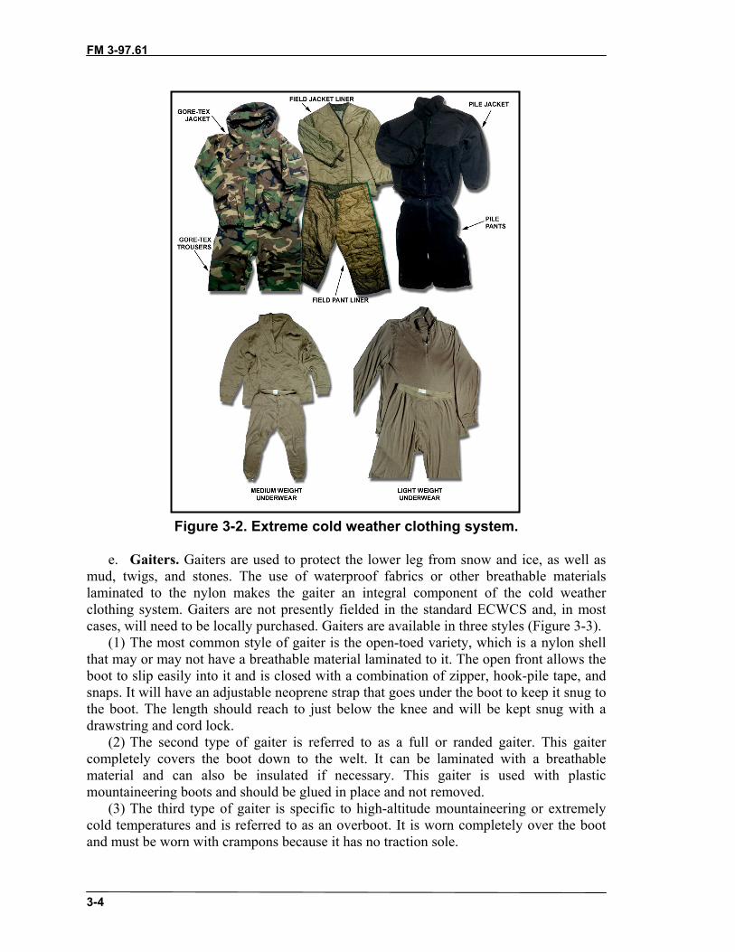
FM 3-97.61
3-4
Figure 3-2. Extreme cold weather clothing system.
e. Gaiters. Gaiters are used to protect the lower leg from snow and ice, as well asmud, twigs, and stones. The use of waterproof fabrics or other breathable materialslaminated to the nylon makes the gaiter an integral component of the cold weatherclothing system. Gaiters are not presently fielded in the standard ECWCS and, in mostcases, will need to be locally purchased. Gaiters are available in three styles (Figure 3-3).
(1) The most common style of gaiter is the open-toed variety, which is a nylon shellthat may or may not have a breathable material laminated to it. The open front allows theboot to slip easily into it and is closed with a combination of zipper, hook-pile tape, andsnaps. It will have an adjustable neoprene strap that goes under the boot to keep it snug tothe boot. The length should reach to just below the knee and will be kept snug with adrawstring and cord lock.
(2) The second type of gaiter is referred to as a full or randed gaiter. This gaitercompletely covers the boot down to the welt. It can be laminated with a breathablematerial and can also be insulated if necessary. This gaiter is used with plasticmountaineering boots and should be glued in place and not removed.
(3) The third type of gaiter is specific to high-altitude mountaineering or extremelycold temperatures and is referred to as an overboot. It is worn completely over the bootand must be worn with crampons because it has no traction sole.

FM 3-97.61
3-5
Figure 3-3. Three types of gaiters.
f. Hand Wear. During operations in mountainous terrain the use of hand wear isextremely important. Even during the best climatic conditions, temperatures in themountains will dip below the freezing point. While mittens are always warmer thangloves, the finger dexterity needed to do most tasks makes gloves the primary coldweather hand wear (Figure 3-4, page 3-6).
(1) The principals that apply to clothing also apply to gloves and mittens. Theyshould provide moisture transfer from the skin to the outer layers―the insulating layermust insulate the hand from the cold and move moisture to the outer layer. The outerlayer must be weather resistant and breathable. Both gloves and mittens should berequired for all soldiers during mountain operations, as well as replacement liners forboth. This will provide enough flexibility to accomplish all tasks and keep the users’hands warm and dry.
(2) Just as the clothing system is worn in layers, gloves and mittens work best usingthe same principle. Retention cords that loop over the wrist work extremely well whenthe wearer needs to remove the outer layer to accomplish a task that requires fine fingerdexterity. Leaving the glove or mitten dangling from the wrist ensures the wearer knowswhere it is at all times.

FM 3-97.61
3-6
Figure 3-4. Hand wear.
g. Headwear. A large majority of heat loss (25 percent) occurs through the head andneck area. The most effective way to counter heat loss is to wear a hat. The best hatavailable to the individual soldier through the military supply system is the black watchcap. Natural fibers, predominately wool, are acceptable but can be bulky and difficult tofit under a helmet. As with clothes and hand wear, man-made fibers are preferred. Forcolder climates a neck gaiter can be added. The neck gaiter is a tube of man-madematerial that fits around the neck and can reach up over the ears and nose (Figure 3-5).For extreme cold, a balaclava can be added. This covers the head, neck, and face leavingonly a slot for the eyes (Figure 3-5). Worn together the combination is warm andprovides for moisture movement, keeping the wearer drier and warmer.
Figure 3-5. Neck gaiter and balaclava.

FM 3-97.61
3-7
h. Helmets. The Kevlar ballistic helmet can be used for most basic mountaineeringtasks. It must be fitted with parachute retention straps and the foam impact pad(Figure 3-6). The level 2 and 3 mountaineer will need a lighter weight helmet for specificclimbing scenerios. Several civilian manufacturers produce an effective helmet.Whichever helmet is selected, it should be designed specifically for mountaineering andadjustable so the user can add a hat under it when needed.
Figure 3-6. Helmets.
i. Eyewear. The military supply system does not currently provide adequateeyewear for mountaineering. Eyewear is divided into two catagories: glacier glasses andgoggles (Figure 3-7). Glacier glasses are sunglasses that cover the entire eye socket.Many operations in the mountains occur above the tree line or on ice and snow surfaceswhere the harmful UV rays of the sun can bombard the eyes from every angle increasingthe likelihood of snowblindness. Goggles for mountain operations should be antifogging.Double or triple lenses work best. UV rays penetrate clouds so the goggles should be UVprotected. Both glacier glasses and goggles are required equipment in the mountains. Thelack of either one can lead to severe eye injury or blindness.
Figure 3-7. Glacier glasses and goggles.

FM 3-97.61
3-8
j. Maintenance of Clothing. Clothing and equipment manufacturers providespecific instructions for proper care. Following these instructions is necessary to ensurethe equipment works as intended.
3-3. CLIMBING SOFTWAREClimbing software refers to rope, cord, webbing, and harnesses. All mountaineeringspecific equipment, to include hardware (see paragraph 3-4), should only be used if it hasthe UIAA certificate of safety. UIAA is the organization that oversees the testing ofmountaineering equipment. It is based in Paris, France, and comprises severalcommissions. The safety commission has established standards for mountaineering andclimbing equipment that have become well recognized throughout the world. Their workcontinues as new equipment develops and is brought into common use. CommunityEurope (CE) recognizes UIAA testing standards and, as the broader-based testing facilityfor the combined European economy, meets or exceeds the UIAA standards for allclimbing and mountaineering equipment produced in Europe. European norm (EN) andCE have been combined to make combined European norm (CEN). While the UnitedStates has no specific standards, American manufacturers have their equipment tested byUIAA to ensure safe operating tolerances.
a. Ropes and Cord. Ropes and cords are the most important pieces ofmountaineering equipment and proper selection deserves careful thought. These items areyour lifeline in the mountains, so selecting the right type and size is of the utmostimportance. All ropes and cord used in mountaineering and climbing today areconstructed with the same basic configuration. The construction technique is referred toas Kernmantle, which is, essentially, a core of nylon fibers protected by a woven sheath,similar to parachute or 550 cord (Figure 3-8).
Figure 3-8. Kernmantle construction.
(1) Ropes come in two types: static and dynamic. This refers to their ability to stretchunder tension. A static rope has very little stretch, perhaps as little as one to two percent,and is best used in rope installations. A dynamic rope is most useful for climbing andgeneral mountaineering. Its ability to stretch up to 1/3 of its overall length makes it theright choice any time the user might take a fall. Dynamic and static ropes come in various

FM 3-97.61
3-9
diameters and lengths. For most military applications, a standard 10.5- or 11-millimeterby 50-meter dynamic rope and 11-millimeter by 45-meter static rope will be sufficient.
(2) When choosing dynamic rope, factors affecting rope selection include intendeduse, impact force, abrasion resistance, and elongation. Regardless of the rope chosen, itshould be UIAA certified.
(3) Cord or small diameter rope is indispensable to the mountaineer. Its many usesmake it a valuable piece of equipment. All cord is static and constructed in the samemanner as larger rope. If used for Prusik knots, the cord’s diameter should be 5 to 7millimeters when used on an 11-mm rope.
b. Webbing and Slings. Loops of tubular webbing or cord, called slings or runners,are the simplest pieces of equipment and some of the most useful. The uses for thesesimple pieces are endless, and they are a critical link between the climber, the rope,carabiners, and anchors. Runners are predominately made from either 9/16-inch or 1-inchtubular webbing and are either tied or sewn by a manufacturer (Figure 3-9). Runners canalso be made from a high-performance fiber known as spectra, which is stronger, moredurable, and less susceptible to ultraviolet deterioration. Runners should be retiredregularly following the same considerations used to retire a rope. For most militaryapplications, a combination of different lengths of runners is adequate.
(1) Tied runners have certain advantages over sewn runners―they are inexpensive tomake, can be untied and threaded around natural anchors, and can be untied and retied toother pieces of webbing to create extra long runners.
(2) Sewn runners have their own advantages―they tend to be stronger, are usuallylighter, and have less bulk than the tied version. They also eliminate a major concern withthe homemade knotted runner―the possibility of the knot untying. Sewn runners come infour standard lengths: 2 inches, 4 inches, 12 inches, and 24 inches. They also come inthree standard widths: 9/16 inch, 11/16 inch, and 1 inch.
Figure 3-9. Tied or sewn runners.

FM 3-97.61
3-10
c. Harnesses. Years ago climbers secured themselves to the rope by wrapping therope around their bodies and tying a bowline-on-a-coil. While this technique is still aviable way of attaching to a rope, the practice is no longer encouraged because of theincreased possibility of injury from a fall. The bowline-on-a-coil is best left for low-angleclimbing or an emergency situation where harness material is unavailable. Climberstoday can select from a wide range of manufactured harnesses. Fitted properly, theharness should ride high on the hips and have snug leg loops to better distribute the forceof a fall to the entire pelvis. This type of harness, referred to as a seat harness, provides acomfortable seat for rappelling (Figure 3-10).
(1) Any harness selected should have one very important feature―a double-passedbuckle. This is a safety standard that requires the waist belt to be passed over and backthrough the main buckle a second time. At least 2 inches of the strap should remain afterdouble-passing the buckle.
(2) Another desirable feature on a harness is adjustable leg loops, which allows asnug fit regardless of the number of layers of clothing worn. Adjustable leg loops allowthe soldier to make a latrine call without removing the harness or untying the rope.
(3) Equipment loops are desirable for carrying pieces of climbing equipment. Forsafety purposes always follow the manufacturer’s directions for tying-in.
(4) A field-expedient version of the seat harness can be constructed by using 22 feetof either 1-inch or 2-inch (preferred) tubular webbing (Figure 3-10). Two double-overhand knots form the leg loops, leaving 4 to 5 feet of webbing coming from one of theleg loops. The leg loops should just fit over the clothing. Wrap the remaining webbingaround the waist ensuring the first wrap is routed through the 6- to 10-inch long strapbetween the double-overhand knots. Finish the waist wrap with a water knot tied astightly as possible. With the remaining webbing, tie a square knot without safeties overthe water knot ensuring a minimum of 4 inches remains from each strand of webbing.
(5) The full body harness incorporates a chest harness with a seat harness (Figure3-10). This type of harness has a higher tie-in point and greatly reduces the chance offlipping backward during a fall. This is the only type of harness that is approved by theUIAA. While these harnesses are safer, they do present several disadvantages―they aremore expensive, are more restrictive, and increase the difficulty of adding or removingclothing. Most mountaineers prefer to incorporate a separate chest harness with their seatharness when warranted.
(6) A separate chest harness can be purchased from a manufacturer, or afield-expedient version can be made from either two runners or a long piece of webbing.Either chest harness is then attached to the seat harness with a carabiner and a length ofwebbing or cord.

FM 3-97.61
3-11
Figure 3-10. Seat harness, field-expedient harness, and full body harness.
3-4. CLIMBING HARDWAREClimbing hardware refers to all the parts and pieces that allow the trained mountainsoldier to accomplish many tasks in the mountains. The importance of this gear to themountaineer is no less than that of the rifle to the infantryman.
a. Carabiners. One of the most versatile pieces of equipment available to themountaineer is the carabiner. This simple piece of gear is the critical connection betweenthe climber, his rope, and the protection attaching him to the mountain. Carabiners mustbe strong enough to hold hard falls, yet light enough for the climber to easily carry aquantity of them. Today’s high tech metal alloys allow carabiners to meet both of theserequirements. Steel is still widely used, but is not preferred for general mountaineering,given other options. Basic carabiner construction affords the user several differentshapes. The oval, the D-shaped, and the pear-shaped carabiner are just some of the typescurrently available. Most models can be made with or without a locking mechanism forthe gate opening (Figure 3-11, page 3-12). If the carabiner does have a lockingmechanism, it is usually referred to as a locking carabiner. When using a carabiner, greatcare should be taken to avoid loading the carabiner on its minor axis and to avoid three-way loading (Figure 3-12, page 3-12).
Note: Great care should be used to ensure all carabiner gates are closed and lockedduring use.

FM 3-97.61
3-12
Figure 3-11. Nonlocking and locking carabiners.
Figure 3-12. Major and minor axes and three-way loading.
(1) The major difference between the oval and the D-shaped carabiner is strength.Because of the design of the D-shaped carabiner, the load is angled onto the spine of the
FM 3-97.61
3-13
carabiner thus keeping it off the gate. The down side is that racking any gear orprotection on the D-shaped carabiner is difficult because the angle of the carabiner forcesall the gear together making it impossible to separate quickly.
(2) The pear-shaped carabiner, specifically the locking version, is excellent forclipping a descender or belay device to the harness. They work well with the munter hitchbelaying knot.
(3) Regardless of the type chosen, all carabiners should be UIAA tested. This testingis extensive and tests the carabiner in three ways―along its major axis, along its minoraxis, and with the gate open.
b. Pitons. A piton is a metal pin that is hammered into a crack in the rock. They aredescribed by their thickness, design, and length (Figure 3-13, page 3-14). Pitons provide asecure anchor for a rope attached by a carabiner. The many different kinds of pitons include:vertical, horizontal, wafer, and angle. They are made of malleable steel, hardened steel, orother alloys. The strength of the piton is determined by its placement rather than its ratedtensile strength. The two most common types of pitons are: blades, which hold whenwedged into tight-fitting cracks, and angles, which hold blade compression when wedgedinto a crack.
(1) Vertical Pitons. On vertical pitons, the blade and eye are aligned. These pitons areused in flush, vertical cracks.
(2) Horizontal Pitons. On horizontal pitons, the eye of the piton is at right angles to theblade. These pitons are used in flush, horizontal cracks and in offset or open-book typevertical or horizontal cracks. They are recommended for use in vertical cracks instead ofvertical pitons because the torque on the eye tends to wedge the piton into place. Thisprovides more holding power than the vertical piton under the same circumstances.
(3) Wafer Pitons. These pitons are used in shallow, flush cracks. They have littleholding power and their weakest points are in the rings provided for the carabiner.
(4) Knife Blade Pitons. These are used in direct-aid climbing. They are small and fitinto thin, shallow cracks. They have a tapered blade that is optimum for both strength andholding power.
(5) Realized Ultimate Reality Pitons. Realized ultimate reality pitons (RURPs) arehatchet-shaped pitons about 1-inch square. They are designed to bite into thin, shallowcracks.
(6) Angle Pitons. These are used in wide cracks that are flush or offset. Maximumstrength is attained only when the legs of the piton are in contact with the opposite sides ofthe crack.
(7) Bong Pitons. These are angle pitons that are more than 3.8 centimeters wide. Bongsare commonly made of steel or aluminum alloy and usually contain holes to reduce weightand accommodate carabiners. They have a high holding power and require less hammeringthan other pitons.
(8) Skyhook (Cliffhangers). These are small hooks that cling to tiny rock protrusions,ledges, or flakes. Skyhooks require constant tension and are used in a downward pulldirection. The curved end will not straighten under body weight. The base is designed toprevent rotation and aid stability.

FM 3-97.61
3-14
Figure 3-13. Various pitons.
c. Piton Hammers. A piton hammer has a flat metal head; a handle made of wood,metal, or fiberglass; and a blunt pick on the opposite side of the hammer (Figure 3-14). Asafety lanyard of nylon cord, webbing, or leather is used to attach it to the climber Thelanyard should be long enough to allow for full range of motion. Most hammers areapproximately 25.5 centimeters long and weigh 12 to 25 ounces. The primary use for apiton hammer is to drive pitons, to be used as anchors, into the rock. The piton hammercan also be used to assist in removing pitons, and in cleaning cracks and rock surfaces toprepare for inserting the piton. The type selected should suit individual preference and theintended use.
Figure 3-14. Piton hammer.

FM 3-97.61
3-15
d. Chocks. “Chocks” is a generic term used to describe the various types of artificialprotection other than bolts or pitons. Chocks are essentially a tapered metal wedgeconstructed in various sizes to fit different sized openings in the rock (Figure 3-15). Thedesign of a chock will determine whether it fits into one of two categories―wedges orcams. A wedge holds by wedging into a constricting crack in the rock. A cam holds byslightly rotating in a crack, creating a camming action that lodges the chock in the crackor pocket. Some chocks are manufactured to perform either in the wedging mode or thecamming mode. One of the chocks that falls into the category of both a wedge and cam isthe hexagonal-shaped or “hex” chock. This type of chock is versatile and comes witheither a cable loop or is tied with cord or webbing. All chocks come in different sizes tofit varying widths of cracks. Most chocks come with a wired loop that is stronger thancord and allows for easier placement. Bigger chocks can be threaded with cord orwebbing if the user ties the chock himself. Care should be taken to place tubing in thechock before threading the cord. The cord used with chocks is designed to be stiffer andstronger than regular cord and is typically made of Kevlar. The advantage of using achock rather than a piton is that a climber can carry many different sizes and use themrepeatedly.
Figure 3-15. Chocks.

FM 3-97.61
3-16
e. Three-Point Camming Device. The three-point camming device’s unique designallows it to be used both as a camming piece and a wedging piece (Figure 3-16). Becauseof this design it is extremely versatile and, when used in the camming mode, will fit awide range of cracks. The three-point camming device comes in several different sizeswith the smaller sizes working in pockets that no other piece of gear would fit in.
Figure 3-16. Three-point camming device.

FM 3-97.61
3-17
f. Spring-Loaded Camming Devices. Spring-loaded camming devices (SLCDs)(Figure 3-17) provide convenient, reliable placement in cracks where standard chocks arenot practical (parallel or flaring cracks or cracks under roofs). SLCDs have three or fourcams rotating around a single or double axis with a rigid or semi-rigid point of attachment.These are placed quickly and easily, saving time and effort. SLCDs are available in manysizes to accommodate different size cracks. Each fits a wide range of crack widths due to therotating cam heads. The shafts may be rigid metal or semi-rigid cable loops. The flexiblecable reduces the risk of stem breakage over an edge in horizontal placements.
Figure 3-17. Spring-loaded camming devices.

FM 3-97.61
3-18
g. Chock Picks. Chock picks are primarily used to extract chocks from rock whenthe they become severely wedged (Figure 3-18). They are also handy to clean crackswith. Made from thin metal, they can be purchased or homemade. When using a chockpick to extract a chock be sure no force is applied directly to the cable juncture. One endof the chock pick should have a hook to use on jammed SLCDs.
Figure18. Chock picks.
h. Bolts. Bolts are screw-like shafts made from metal that are drilled into rock toprovide protection (Figure 3-19). The two types are contraction bolts and expansion bolts.Contraction bolts are squeezed together when driven into a rock. Expansion bolts pressaround a surrounding sleeve to form a snug fit into a rock. Bolts require drilling a holeinto a rock, which is time-consuming, exhausting, and extremely noisy. Once emplaced,bolts are the most secure protection for a multidirectional pull. Bolts should be used onlywhen chocks and pitons cannot be emplaced. A bolt is hammered only when it is the nailor self-driving type.
(1) A hanger (for carabiner attachment) and nut are placed on the bolt. The bolt isthen inserted and driven into the hole. Because of this requirement, a hand drill must becarried in addition to a piton hammer. Hand drills (also called star drills) are available indifferent sizes, brands, and weights. A hand drill should have a lanyard to prevent loss.
(2) Self-driving bolts are quicker and easier to emplace. These require a hammer, boltdriver, and drilling anchor, which is driven into the rock. A bolt and carrier are thensecured to the emplaced drilling anchor. All metal surfaces should be smooth and free ofrust, corrosion, dirt, and moisture. Burrs, chips, and rough spots should be filed smoothand wire-brushed or rubbed clean with steel wool. Items that are cracked or warpedindicate excessive wear and should be discarded.

FM 3-97.61
3-19
Figure 3-19. Bolts and hangers.
i. Belay Devices. Belay devices range from the least equipment intensive (the bodybelay) to high-tech metal alloy pieces of equipment. Regardless of the belay devicechoosen, the basic principal remains the same―friction around or through the belaydevice controls the ropes’ movement. Belay devices are divided into three categories: theslot, the tuber, and the mechanical camming device (Figure 3-20).
(1) The slot is a piece of equipment that attaches to a locking carabiner in the harness;a bight of rope slides through the slot and into the carabiner for the belay. The mostcommon slot type belay device is the Sticht plate.
(2) The tuber is used exactly like the slot but its shape is more like a cone or tube.(3) The mechanical camming device is a manufactured piece of equipment that
attaches to the harness with a locking carabiner. The rope is routed through this device sothat when force is applied the rope is cammed into a highly frictioned position.
Figure 3-20. Slot, tuber, mechanical camming device.

FM 3-97.61
3-20
j. Descenders. One piece of equipment used for generations as a descender is thecarabiner. A figure-eight is another useful piece of equipment and can be used inconjunction with the carabiner for descending (Figure 3-21).
Note: All belay devices can also be used as descending devices.
Figure 3-21. Figure-eights.
k. Ascenders. Ascenders may be used in other applications such as a personal safetyor hauling line cam. All modern ascenders work on the principle of using a cam-likedevice to allow movement in one direction. Ascenders are primarily made of metal alloysand come in a variety of sizes (Figure 3-22). For difficult vertical terrain, two ascenderswork best. For lower angle movement, one ascender is sufficient. Most manufacturersmake ascenders as a right and left-handed pair.
Figure 3-22. Ascenders.
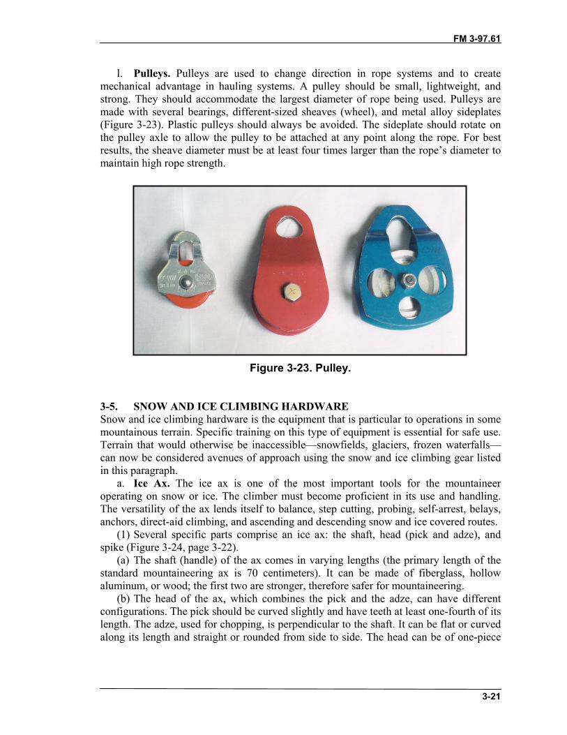
FM 3-97.61
3-21
l. Pulleys. Pulleys are used to change direction in rope systems and to createmechanical advantage in hauling systems. A pulley should be small, lightweight, andstrong. They should accommodate the largest diameter of rope being used. Pulleys aremade with several bearings, different-sized sheaves (wheel), and metal alloy sideplates(Figure 3-23). Plastic pulleys should always be avoided. The sideplate should rotate onthe pulley axle to allow the pulley to be attached at any point along the rope. For bestresults, the sheave diameter must be at least four times larger than the rope’s diameter tomaintain high rope strength.
Figure 3-23. Pulley.
3-5. SNOW AND ICE CLIMBING HARDWARESnow and ice climbing hardware is the equipment that is particular to operations in somemountainous terrain. Specific training on this type of equipment is essential for safe use.Terrain that would otherwise be inaccessible—snowfields, glaciers, frozen waterfalls—can now be considered avenues of approach using the snow and ice climbing gear listedin this paragraph.
a. Ice Ax. The ice ax is one of the most important tools for the mountaineeroperating on snow or ice. The climber must become proficient in its use and handling.The versatility of the ax lends itself to balance, step cutting, probing, self-arrest, belays,anchors, direct-aid climbing, and ascending and descending snow and ice covered routes.
(1) Several specific parts comprise an ice ax: the shaft, head (pick and adze), andspike (Figure 3-24, page 3-22).
(a) The shaft (handle) of the ax comes in varying lengths (the primary length of thestandard mountaineering ax is 70 centimeters). It can be made of fiberglass, hollowaluminum, or wood; the first two are stronger, therefore safer for mountaineering.
(b) The head of the ax, which combines the pick and the adze, can have differentconfigurations. The pick should be curved slightly and have teeth at least one-fourth of itslength. The adze, used for chopping, is perpendicular to the shaft. It can be flat or curvedalong its length and straight or rounded from side to side. The head can be of one-piece

FM 3-97.61
3-22
construction or have replaceable picks and adzes. The head should have a hole directlyabove the shaft to allow for a leash to be attached.
(c) The spike at the bottom of the ax is made of the same material as the head andcomes in a variety of shapes.
(2) As climbing becomes more technical, a shorter ax is much more appropriate, andadding a second tool is a must when the terrain becomes vertical. The shorter ax has allthe attributes of the longer ax, but it is anywhere from 40 to 55 centimeters long and canhave a straight or bent shaft depending on the preference of the user.
b. Ice Hammer. The ice hammer is as short or shorter than the technical ax (Figure3-24). It is used for pounding protection into the ice or pitons into the rock. The onlydifference between the ice ax and the ice hammer is the ice hammer has a hammerheadinstead of an adze. Most of the shorter ice tools have a hole in the shaft to which a leashis secured, which provides a more secure purchase in the ice.
Figure 3-24. Ice ax and ice hammers.
c. Crampons. Crampons are used when the footing becomes treacherous. They havemultiple spikes on the bottom and spikes protruding from the front (Figure 3-25). Twotypes of crampons are available: flexible and rigid. Regardless of the type of cramponchosen, fit is the most important factor associated with crampon wear. The cramponshould fit snugly on the boot with a minimum of 1 inch of front point protruding. Strapsshould fit snugly around the foot and any long, loose ends should be trimmed. Bothflexible and rigid crampons come in pairs, and any tools needed for adjustment will beprovided by the manufacturer.
(1) The hinged or flexible crampon is best used when no technical ice climbing willbe done. It is designed to be used with soft, flexible boots, but can be attached to plastic

FM 3-97.61
3-23
mountaineering boots. The flexible crampon gets its name from the flexible hinge on thecrampon itself. All flexible crampons are adjustable for length while some allow forwidth adjustment. Most flexible crampons will attach to the boot by means of a strapsystem. The flexible crampon can be worn with a variety of boot types.
(2) The rigid crampon, as its name implies, is rigid and does not flex. This type ofcrampon is designed for technical ice climbing, but can be used on less vertical terrain.The rigid crampon can only be worn with plastic mountaineering boots. Rigid cramponswill have a toe and heel bail attachment with a strap that wraps around the ankle.
Figure 3-25. Crampons.
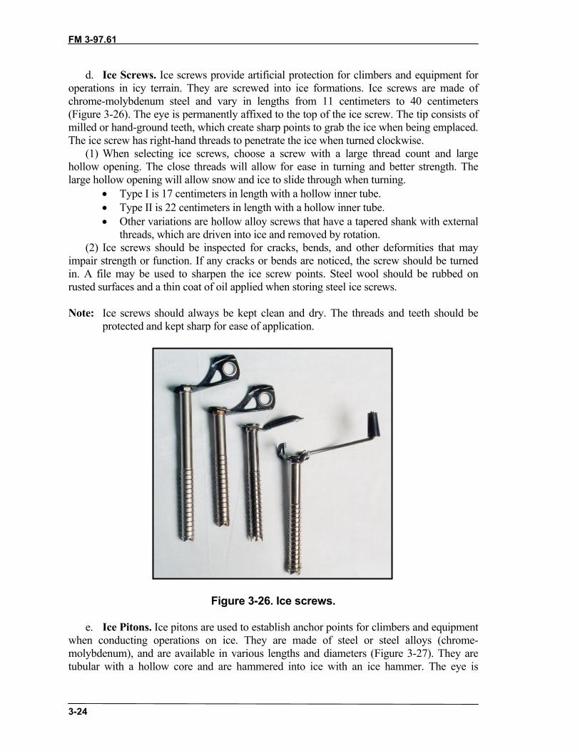
FM 3-97.61
3-24
d. Ice Screws. Ice screws provide artificial protection for climbers and equipment foroperations in icy terrain. They are screwed into ice formations. Ice screws are made ofchrome-molybdenum steel and vary in lengths from 11 centimeters to 40 centimeters(Figure 3-26). The eye is permanently affixed to the top of the ice screw. The tip consists ofmilled or hand-ground teeth, which create sharp points to grab the ice when being emplaced.The ice screw has right-hand threads to penetrate the ice when turned clockwise.
(1) When selecting ice screws, choose a screw with a large thread count and largehollow opening. The close threads will allow for ease in turning and better strength. Thelarge hollow opening will allow snow and ice to slide through when turning.
• Type I is 17 centimeters in length with a hollow inner tube.• Type II is 22 centimeters in length with a hollow inner tube.• Other variations are hollow alloy screws that have a tapered shank with external
threads, which are driven into ice and removed by rotation.(2) Ice screws should be inspected for cracks, bends, and other deformities that may
impair strength or function. If any cracks or bends are noticed, the screw should be turnedin. A file may be used to sharpen the ice screw points. Steel wool should be rubbed onrusted surfaces and a thin coat of oil applied when storing steel ice screws.
Note: Ice screws should always be kept clean and dry. The threads and teeth should beprotected and kept sharp for ease of application.
Figure 3-26. Ice screws.
e. Ice Pitons. Ice pitons are used to establish anchor points for climbers and equipmentwhen conducting operations on ice. They are made of steel or steel alloys (chrome-molybdenum), and are available in various lengths and diameters (Figure 3-27). They aretubular with a hollow core and are hammered into ice with an ice hammer. The eye is

FM 3-97.61
3-25
permanently fixed to the top of the ice piton. The tip may be beveled to help grab the ice tofacilitate insertion. Ice pitons are extremely strong when placed properly in hard ice. Theycan, however, pull out easily on warm days and require a considerable amount of effort toextract in cold temperatures.
Figure 3-27. Ice piton.
f. Wired Snow Anchors. The wired snow anchor (or fluke) provides security forclimbers and equipment in operations involving steep ascents by burying the snow anchorinto deep snow (Figure 3-28, page 3-26). The fluted anchor portion of the snow anchor ismade of aluminum. The wired portion is made of either galvanized steel or stainless steel.Fluke anchors are available in various sizes―their holding ability generally increases withsize. They are available with bent faces, flanged sides, and fixed cables. Common types are:
• Type I is 22 by 14 centimeters. Minimum breaking strength of the swaged wireloop is 600 kilograms.
• Type II is 25 by 20 centimeters. Minimum breaking strength of the swaged wireloop is 1,000 kilograms.
The wired snow anchor should be inspected for cracks, broken wire strands, and slippage ofthe wire through the swage. If any cracks, broken wire strands, or slippage is noticed, thesnow anchor should be turned in.
g. Snow Picket. The snow picket is used in constructing anchors in snow and ice(Figure 3-28, page 3-26). The snow picket is made of a strong aluminum alloy 3 millimetersthick by 4 centimeters wide, and 45 to 90 centimeters long. They can be angled or T–sectionstakes. The picket should be inspected for bends, chips, cracks, mushrooming ends, andother deformities. The ends should be filed smooth. If bent or cracked, the picket should beturned in for replacement.

FM 3-97.61
3-26
Figure 3-28. Snow anchors, flukes, and pickets.
3-6. SUSTAINABILITY EQUIPMENTThis paragraph describes all additional equipment not directly involved with climbing. Thisequipment is used for safety (avalanche equipment, wands), bivouacs, movement, andcarrying gear. While not all of it will need to be carried on all missions, having theequipment available and knowing how to use it correctly will enhance the unit’s capabilityin mountainous terrain.
a. Snow Saw. The snow saw is used to cut into ice and snow. It can be used in stepcutting, in shelter construction, for removing frozen obstacles, and for cutting snow stabilitytest pits. The special tooth design of the snow saw easily cuts into frozen snow and ice. Theblade is a rigid aluminum alloy of high strength about 3 millimeters thick and 38 centimeterslong with a pointed end to facilitate entry on the forward stroke. The handle is eitherwooden or plastic and is riveted to the blade for a length of about 50 centimeters. The bladeshould be inspected for rust, cracks, warping, burrs, and missing or dull teeth. A file canrepair most defects, and steel wool can be rubbed on rusted areas. The handle should beinspected for cracks, bends, and stability. On folding models, the hinge and nuts should besecure. If the saw is beyond repair, it should not be used.
b. Snow Shovel. The snow shovel is used to cut and remove ice and snow. It can beused for avalanche rescue, shelter construction, step cutting, and removing obstacles. Thesnow shovel is made of a special, lightweight aluminum alloy. The handle should betelescopic, folding, or removable to be compact when not in use. The shovel should have aflat or rounded bottom and be of strong construction. The shovel should be inspected forcracks, bends, rust, and burrs. A file and steel wool can remove rust and put an edge on theblade of the shovel. The handle should be inspected for cracks, bends, and stability. If theshovel is beyond repair, it should be turned in.
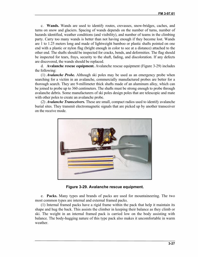
FM 3-97.61
3-27
c. Wands. Wands are used to identify routes, crevasses, snow-bridges, caches, andturns on snow and glaciers. Spacing of wands depends on the number of turns, number ofhazards identified, weather conditions (and visibility), and number of teams in the climbingparty. Carry too many wands is better than not having enough if they become lost. Wandsare 1 to 1.25 meters long and made of lightweight bamboo or plastic shafts pointed on oneend with a plastic or nylon flag (bright enough in color to see at a distance) attached to theother end. The shafts should be inspected for cracks, bends, and deformities. The flag shouldbe inspected for tears, frays, security to the shaft, fading, and discoloration. If any defectsare discovered, the wands should be replaced.
d. Avalanche rescue equipment. Avalanche rescue equipment (Figure 3-29) includesthe following:
(1) Avalanche Probe. Although ski poles may be used as an emergency probe whensearching for a victim in an avalanche, commercially manufactured probes are better for athorough search. They are 9-millimeter thick shafts made of an aluminum alloy, which canbe joined to probe up to 360 centimeters. The shafts must be strong enough to probe throughavalanche debris. Some manufacturers of ski poles design poles that are telescopic and matewith other poles to create an avalanche probe.
(2) Avalanche Transceivers. These are small, compact radios used to identify avalancheburial sites. They transmit electromagnetic signals that are picked up by another transceiveron the receive mode.
Figure 3-29. Avalanche rescue equipment.
e. Packs. Many types and brands of packs are used for mountaineering. The twomost common types are internal and external framed packs.
(1) Internal framed packs have a rigid frame within the pack that help it maintain itsshape and hug the back. This assists the climber in keeping their balance as they climb orski. The weight in an internal framed pack is carried low on the body assisting withbalance. The body-hugging nature of this type pack also makes it uncomfortable in warmweather.

FM 3-97.61
3-28
(2) External framed packs suspend the load away from the back with a ladder-likeframe. The frame helps transfer the weight to the hips and shoulders easier, but can becumbersome when balance is needed for climbing and skiing.
(3) Packs come in many sizes and should be sized appropriately for the individualaccording to manufacturer’s specifications. Packs often come with many unneededfeatures. A good rule of thumb is: The simpler the pack, the better it will be.
f. Stoves. When selecting a stove one must define its purpose―will the stove beused for heating, cooking or both? Stoves or heaters for large elements can be large andcumbersome. Stoves for smaller elements might just be used for cooking and makingwater, and are simple and lightweight. Stoves are a necessity in mountaineering forcooking and making water from snow and ice. When choosing a stove, factors that shouldbe considered are weight, altitude and temperature where it will be used, fuel availability,and its reliability.
(1) There are many choices in stove design and in fuel types. White gas, kerosene,and butane are the common fuels used. All stoves require a means of pressurization toforce the fuel to the burner. Stoves that burn white gas or kerosene have a hand pump togenerate the pressurization and butane stoves have pressurized cartridges. All stoves needto vaporize the liquid fuel before it is burned. This can be accomplished by burning asmall amount of fuel in the burner cup assembly, which will vaporize the fuel in the fuelline.
(2) Stoves should be tested and maintained prior to a mountaineering mission. Theyshould be easy to clean and repair during an operation. The reliability of the stove has ahuge impact on the success of the mission and the morale of personnel.
g. Tents. When selecting a tent, the mission must be defined to determine thenumber of people the tent will accommodate. The climate the tents will be used in is alsoof concern. A tent used for warmer temperatures will greatly differ from tents used in acolder, more harsh environment. Manufacturers of tents offer many designs of differentsizes, weights, and materials.
(1) Mountaineering tents are made out of a breathable or weatherproof material. Asingle-wall tent allows for moisture inside the tent to escape through the tent’s material.A double-wall tent has a second layer of material (referred to as a fly) that covers the tent.The fly protects against rain and snow and the space between the fly and tent helpsmoisture to escape from inside. Before using a new tent, the seams should be treated withseam sealer to prevent moisture from entering through the stitching.
(2) The frame of a tent is usually made of an aluminum or carbon fiber pole. Thepoles are connected with an elastic cord that allows them to extend, connect, and becomelong and rigid. When the tent poles are secured into the tent body, they create the shapeof the tent.
(3) Tents are rated by a “relative strength factor,” the speed of wind a tent canwithstand before the frame deforms. Temperature and expected weather for the missionshould be determined before choosing the tent.
h. Skis. Mountaineering skis are wide and short. They have a binding that pivots atthe toe and allows for the heel to be free for uphill travel or locked for downhill.Synthetic skins with fibers on the bottom can be attached to the bottom of the ski andallow the ski to travel forward and prevent slipping backward. The skins aid in travelinguphill and slow down the rate of descents. Wax can be applied to the ski to aid in ascents

FM 3-97.61
3-29
instead of skins. Skis can decrease the time needed to reach an objective depending onthe ability of the user. Skis can make crossing crevasses easier because of the loaddistribution, and they can become a makeshift stretcher for casualties. Ski techniques canbe complicated and require thorough training for adequate proficiency.
i. Snowshoes. Snowshoes are the traditional aid to snow travel that attach to mostfootwear and have been updated into small, lightweight designs that are more efficientthan older models. Snowshoes offer a large displacement area on top of soft snowpreventing tiresome post-holing. Some snowshoes come equipped with a crampon likebinding that helps in ascending steep snow and ice. Snowshoes are slower than skis, butare better suited for mixed terrain, especially if personnel are not experienced with the artof skiing. When carrying heavy packs, snowshoes can be easier to use than skis.
j. Ski poles. Ski poles were traditionally designed to assist in balance during skiing.They have become an important tool in mountaineering for aid in balance while hiking,snowshoeing, and carrying heavy packs. They can take some of the weight off of thelower body when carrying a heavy pack. Some ski poles are collapsible for ease ofpacking when not needed (Figure 3-30). The basket at the bottom prevents the pole fromplunging deep into the snow and, on some models, can be detached so the pole becomesan avalanche or crevasse probe. Some ski poles come with a self-arrest grip, but shouldnot be the only means of protection on technical terrain.
Figure 3-30. Collapsible ski poles.
k. Sleds. Sleds vary greatly in size, from the squad-size Ahkio, a component of the10-man arctic tent system, to the one-person skow. Regardless of the size, sleds are aninvaluable asset during mountainous operations when snow and ice is the primary surfaceon which to travel. Whichever sled is chosen, it must be attachable to the person orpeople that will be pulling it. Most sleds are constructed using fiberglass bottoms with orwithout exterior runners. Runners will aid the sleds ability to maintain a true track in thesnow. The sled should also come with a cover of some sort―whether nylon or canvas, acover is essential for keeping the components in the sled dry. Great care should be taken
FM 3-97.61
3-30
when packing the sled, especially when hauling fuel. Heavier items should be carriedtowards the rear of the sled and lighter items towards the front.
l. Headlamps. A headlamp is a small item that is not appreciated until it is needed.It is common to need a light source and the use of both hands during limited lightconditions in mountaineering operations. A flashlight can provide light, but can becumbersome when both hands are needed. Most headlamps attach to helmets by means ofelastic bands.
(1) When choosing a headlamp, ensure it is waterproof and the battery apparatus issmall. All components should be reliable in extreme weather conditions. When the lightis being packed, care should be taken that the switch doesn’t accidentally activate and useprecious battery life.
(2) The battery source should compliment the resupply available. Most lights willaccept alkaline, nickel-cadmium, or lithium batteries. Alkaline battery life diminishesquickly in cold temperatures, nickel-cadmium batteries last longer in cold but require arecharging unit, and lithium batteries have twice the voltage so modifications arerequired.
Section II. EQUIPMENT PACKINGEquipment brought on a mission is carried in the pack, worn on the body, or hauled in asled (in winter). Obviously, the rucksack and sled (or Ahkio) can hold much more than aclimber can carry. They would be used for major bivouac gear, food, water, first aid kits,climbing equipment, foul weather shells, stoves, fuel, ropes, and extra ammunition anddemolition materials, if needed.
3-7. CHOICE OF EQUIPMENTMission requirements and unit SOP will influence the choice of gear carried but thefollowing lists provide a sample of what should be considered during mission planning.
a. Personal Gear. Personal gear includes emergency survival kit containingsignaling material, fire starting material, food procurement material, and waterprocurement material. Pocket items should include a knife, whistle, pressure bandage,notebook with pen or pencil, sunglasses, sunblock and lip protection, map, compass andor altimeter.
b. Standard Gear. Standard gear that can be individually worn or carried includescushion sole socks; combat boots or mountain boots, if available; BDU and cap; LCEwith canteens, magazine pouches, and first aid kit; individual weapon; a large rucksackcontaining waterproof coat and trousers, polypropylene top, sweater, or fleece top;helmet; poncho; and sleeping bag.

FM 3-97.61
3-31
CAUTIONCotton clothing, due to its poor insulating andmoisture-wicking characteristics, is virtually useless inmost mountain climates, the exception being hot,desert, or jungle mountain environments. Cottonclothing should be replaced with synthetic fabricclothing.
c. Mountaineering Equipment and Specialized Gear. This gear includes:• Sling rope or climbing harness.• Utility cord(s).• Nonlocking carabiners.• Locking carabiner(s).• Rappelling gloves.• Rappel/belay device.• Ice ax.• Crampons.• Climbing rope, one per climbing team.• Climbing rack, one per climbing team.
d. Day Pack. When the soldier plans to be away from the bivouac site for the day ona patrol or mountaineering mission, he carries a light day pack. This pack should containthe following items:
• Extra insulating layer: polypropylene, pile top, or sweater.• Protective layer: waterproof jacket and pants, rain suit, or poncho.• First aid kit.• Flashlight or headlamp.• Canteen.• Cold weather hat or scarf.• Rations for the time period away from the base camp.• Survival kit.• Sling rope or climbing harness.• Carabiners.• Gloves.• Climbing rope, one per climbing team.• Climbing rack, one per climbing team.
e. Squad or Team Safety Pack. When a squad-sized element leaves the bivouacsite, squad safety gear should be carried in addition to individual day packs. This caneither be loaded into one rucksack or cross-loaded among the squad members. In theevent of an injury, casualty evacuation, or unplanned bivouac, these items may make thedifference between success and failure of the mission.
• Sleeping bag.• Sleeping mat.
FM 3-97.61
3-32
• Squad stove.• Fuel bottle.
f. The Ten Essentials. Regardless of what equipment is carried, the individualmilitary mountaineer should always carry the “ten essentials” when moving through themountains.
(1) Map.(2) Compass, Altimeter, and or GPS.(3) Sunglasses and Sunscreen. (a) In alpine or snow-covered sub-alpine terrain, sunglasses are a vital piece of
equipment for preventing snow blindness. They should filter 95 to 100 percent ofultraviolet light. Side shields, which minimize the light entering from the side, shouldpermit ventilation to help prevent lens fogging. At least one extra pair of sunglassesshould be carried by each independent climbing team.
(b) Sunscreens should have an SPF factor of 15 or higher. For lip protection, a totalUV blocking lip balm that resists sweating, washing, and licking is best. This lipprotection should be carried in the chest pocket or around the neck to allow frequentreapplication.
(4) Extra Food. One day’s worth extra of food should be carried in case of delaycaused by bad weather, injury, or navigational error.
(5) Extra Clothing. The clothing used during the active part of a climb, andconsidered to be the basic climbing outfit, includes socks, boots, underwear, pants,blouse, sweater or fleece jacket, hat, gloves or mittens, and foul weather gear(waterproof, breathable outerwear or waterproof rain suit).
(a) Extra clothing includes additional layers needed to make it through the long,inactive hours of an unplanned bivouac. Keep in mind the season when selectingthis gear.
• Extra underwear to switch out with sweat-soaked underwear.• Extra hats or balaclavas. • Extra pair of heavy socks. • Extra pair of insulated mittens or gloves. • In winter or severe mountain conditions, extra insulation for the upper body
and the legs.(b) To back up foul weather gear, bring a poncho or extra-large plastic trash bag. A
reflective emergency space blanket can be used for hypothermia first aid and emergencyshelter. Insulated foam pads prevent heat loss while sitting or lying on snow. Finally, abivouac sack can help by protecting insulating layers from the weather, cutting the wind,and trapping essential body heat inside the sack.
(6) Headlamp and or Flashlight. Headlamps provide the climber a hands-freecapability, which is important while climbing, working around the camp, and employingweapons systems. Miniature flashlights can be used, but commercially availableheadlamps are best. Red lens covers can be fabricated for tactical conditions. Sparebatteries and spare bulbs should also be carried.
(7) First-aid Kit. Decentralized operations, the mountain environment―steep, slickterrain and loose rock combined with heavy packs, sharp tools, and fatigue―requireseach climber to carry his own first-aid kit. Common mountaineering injuries that can beexpected are punctures and abrasions with severe bleeding, a broken bone, serious sprain,
FM 3-97.61
3-33
and blisters. Therefore, the kit should contain at least enough material to stabilize theseconditions. Pressure dressings, gauze pads, elastic compression wrap, small adhesivebandages, butterfly bandages, moleskin, adhesive tape, scissors, cleanser, latex glovesand splint material (if above tree line) should all be part of the kit.
(8) Fire Starter. Fire starting material is key to igniting wet wood for emergencycampfires. Candles, heat tabs, and canned heat all work. These can also be used for quickwarming of water or soup in a canteen cup. In alpine zones above tree line with noavailable firewood, a stove works as an emergency heat source.
(9) Matches and Lighter. Lighters are handy for starting fires, but they should bebacked up by matches stored in a waterproof container with a strip of sandpaper.
(10) Knife. A multipurpose pocket tool should be secured with cord to the belt,harness, or pack.
g. Other Essential Gear. Other essential gear may be carried depending on missionand environmental considerations.
(1) Water and Water Containers. These include wide-mouth water bottles for watercollection; camel-back type water holders for hands-free hydration; and a small length ofplastic tubing for water procurement at snow-melt seeps and rainwater puddles on barerock.
(2) Ice Ax. The ice ax is essential for travel on snowfields and glaciers as well assnow-covered terrain in spring and early summer. It helps for movement on steep screeand on brush and heather covered slopes, as well as for stream crossings.
(3) Repair Kit. A repair kit should include:• Stove tools and spare parts.• Duct tape.• Patches.• Safety pins.• Heavy-duty thread.• Awl and or needles.• Cord and or wire.• Small pliers (if not carrying a multipurpose tool).• Other repair items as needed.
(4) Insect Repellent.(5) Signaling Devices.(6) Snow Shovel.
3-8. TIPS ON PACKINGWhen loading the internal frame pack the following points should be considered.
a. In most cases, speed and endurance are enhanced if the load is carried more by thehips (using the waist belt) and less by the shoulders and back. This is preferred formovement over trails or less difficult terrain. By packing the lighter, more compressibleitems (sleeping bag, clothing) in the bottom of the rucksack and the heavier gear (stove,food, water, rope, climbing hardware, extra ammunition) on top, nearer the shoulderblades, the load is held high and close to the back, thus placing the most weight onthe hips.

FM 3-97.61
3-34
b. In rougher terrain it pays to modify the pack plan. Heavy articles of gear areplaced lower in the pack and close to the back, placing more weight on the shoulders andback. This lowers the climber’s center of gravity and helps him to better keep his balance.
c. Equipment that may be needed during movement should be arranged for quickaccess using either external pockets or placing immediately underneath the top flap of thepack. As much as possible, this placement should be standardized across the team so thatnecessary items can be quickly reached without unnecessary unpacking of the pack inemergencies.
d. The pack and its contents should be soundly waterproofed. Clothing and sleepingbag are separately sealed and then placed in the larger wet weather bag that lines therucksack. Zip-lock plastic bags can be used for small items, which are then organized intocolor-coded stuffsacks. A few extra-large plastic garbage bags should be carried for avariety of uses―spare waterproofing, emergency bivouac shelter, and waterprocurement, among others.
e. The ice ax, if not carried in hand, should be stowed on the outside of the packwith the spike up and the adze facing forward or to the outside, and be securely fastened.Mountaineering packs have ice ax loops and buckle fastening systems for this. If not, theice ax is placed behind one of the side pockets, as stated above, and then tied in place.
f. Crampons should be secured to the outside rear of the pack with thepoints covered.

FM 3-97.61(TC 90-6-1)
4-1
CHAPTER 4ROPE MANAGEMENT AND KNOTS
The rope is a vital piece of equipment to the mountaineer. Whenclimbing, rappelling, or building various installations, the mountaineermust know how to properly utilize and maintain this piece of equipment. Ifthe rope is not managed or maintained properly, serious injury may occur.This chapter discusses common rope terminology, managementtechniques, care and maintenance procedures, and knots.
SECTION I. PREPARATION, CARE AND MAINTENANCE,INSPECTION, TERMINOLOGY
The service life of a rope depends on the frequency of use, applications (rappelling,climbing, rope installations), speed of descent, surface abrasion, terrain, climate, andquality of maintenance. Any rope may fail under extreme conditions (shock load, sharpedges, misuse).
4-1. PREPARATIONThe mountaineer must select the proper rope for the task to be accomplished according totype, diameter, length, and tensile strength. It is important to prepare all ropes beforedeparting on a mission. Avoid rope preparation in the field.
a. Packaging. New rope comes from the manufacturer in differentconfigurations―boxed on a spool in various lengths, or coiled and bound in somemanner. Precut ropes are usually packaged in a protective cover such as plastic or burlap.Do not remove the protective cover until the rope is ready for use.
b. Securing the Ends of the Rope: If still on a spool, the rope must be cut to thedesired length. All ropes will fray at the ends unless they are bound or seared. Both staticand dynamic rope ends are secured in the same manner. The ends must be heated to themelting point so as to attach the inner core strands to the outer sheath. By fusing the twotogether, the sheath cannot slide backward or forward. Ensure that this is only done to theends of the rope. If the rope is exposed to extreme temperatures, the sheath could beweakened, along with the inner core, reducing overall tensile strength. The ends may alsobe dipped in enamel or lacquer for further protection.
4-2. CARE AND MAINTENANCEThe rope is a climber’s lifeline. It must be cared for and used properly. These generalguidelines should be used when handling ropes.
a. Do not step on or drag ropes on the ground unnecessarily. Small particles of dirtwill be ground between the inner strands and will slowly cut them.
b. While in use, do not allow the rope to come into contact with sharp edges. Nylonrope is easily cut, particularly when under tension. If the rope must be used over a sharpedge, pad the edge for protection.
c. Always keep the rope as dry as possible. Should the rope become wet, hang it inlarge loops off the ground and allow it to dry. Never dry a rope with high heat or in directsunlight.

FM 3-97.61
4-2
d. Never leave a rope knotted or tightly stretched for longer than necessary. Overtime it will reduce the strength and life of the rope.
e. Never allow one rope to continuously rub over or against another. Allowingrope-on-rope contact with nylon rope is extremely dangerous because the heat producedby the friction will cause the nylon to melt.
f. Inspect the rope before each use for frayed or cut spots, mildew or rot, or defectsin construction (new rope).
g. The ends of the rope should be whipped or melted to prevent unraveling.h. Do not splice ropes for use in mountaineering.i. Do not mark ropes with paints or allow them to come in contact with oils or
petroleum products. Some of these will weaken or deteriorate nylon.j. Never use a mountaineering rope for any purpose except mountaineering.k. Each rope should have a corresponding rope log (DA Form 5752-R, Rope History
and Usage), which is also a safety record. It should annotate use, terrain, weather,application, number of falls, dates, and so on, and should be annotated each time the ropeis used (Figure 4-1). DA Form 5752-R is authorized for local reproduction on 8 1/2- by11-inch paper.
Figure 4-1. Example of completed DA Form 5752-R.
l. Never subject the rope to high heat or flame. This will significantly weaken it.m. All ropes should be washed periodically to remove dirt and grit, and rinsed
thoroughly. Commercial rope washers are made from short pieces of modified pipe thatconnect to any faucet. Pinholes within the pipe force water to circulate around and scrubthe rope as you slowly feed it through the washer. Another method is to machine wash,
FM 3-97.61
4-3
on a gentle cycle, in cold water with a nylon safe soap, never bleach or harsh cleansers.Ensure that only front loading washing machine are used to wash ropes.
n. Ultraviolet radiation (sunlight) tends to deteriorate nylon over long periods oftime. This becomes important if rope installations are left in place over a number ofmonths.
o. When not in use, ropes should be loosely coiled and hung on wooden pegs ratherthan nails or other metal objects. Storage areas should be relatively cool with lowhumidity levels to prevent mildew or rotting. Rope may also be loosely stacked andplaced in a rope bag and stored on a shelf. Avoid storage in direct sunlight, as theultraviolet radiation will deteriorate the nylon over long periods
4-3. INSPECTIONRopes should be inspected before and after each use, especially when working aroundloose rock or sharp edges.
a. Although the core of the kernmantle rope cannot be seen, it is possible to damagethe core without damaging the sheath. Check a kernmantle rope by carefully inspectingthe sheath before and after use while the rope is being coiled. When coiling, be aware ofhow the rope feels as it runs through the hands. Immediately note and tie off any lumps ordepressions felt.
b. Damage to the core of a kernmantle rope usually consists of filaments or yarnbreakage that results in a slight retraction. If enough strands rupture, a localized reductionin the diameter of the rope results in a depression that can be felt or even seen.
c. Check any other suspected areas further by putting them under tension (the weightof one person standing on a Prusik tensioning system is about maximum). This procedurewill emphasize the lump or depression by separating the broken strands and enlarging thedip. If a noticeable difference in diameter is obvious, retire the rope immediately.
d. Many dynamic kernmantle ropes are quite soft. They may retain an indentionoccasionally after an impact or under normal use without any trauma to the core. Whendamage is suspected, patiently inspect the sheath for abnormalities. Damage to the sheathdoes not always mean damage to the core. Inspect carefully.
4-4. TERMINOLOGYWhen using ropes, understanding basic terminology is important. The terms explained inthis section are the most commonly used in military mountaineering. (Figure 4-2, page4-4, illustrates some of these terms.)
a. Bight. A bight of rope is a simple bend of rope in which the rope does not crossitself.
b. Loop. A loop is a bend of a rope in which the rope does cross itself.c. Half Hitch. A half hitch is a loop that runs around an object in such a manner as
to lock or secure itself.d. Turn. A turn wraps around an object, providing 360-degree contact.e. Round Turn. A round turn wraps around an object one and one-half times. A
round turn is used to distribute the load over a small diameter anchor (3 inches or less). Itmay also be used around larger diameter anchors to reduce the tension on the knot, orprovide added friction.
f. Running End. A running end is the loose or working end of the rope.

FM 3-97.61
4-4
g. Standing Part. The standing part is the static, stationary, or nonworking end ofthe rope.
h. Lay. The lay is the direction of twist used in construction of the rope.i. Pigtail. The pigtail (tail) is the portion of the running end of the rope between the
safety knot and the end of the rope.j. Dress. Dress is the proper arrangement of all the knot parts, removing
unnecessary kinks, twists, and slack so that all rope parts of the knot make contact.
Figure 4-2. Examples of roping terminology.
Section II. COILING, CARRYING, THROWINGThe ease and speed of rope deployment and recovery greatly depends upon techniqueand practice.
4-5. COILING AND CARRYING THE ROPEUse the butterfly or mountain coil to coil and carry the rope. Each is easy to accomplishand results in a minimum amount of kinks, twists, and knots later during deployment.
a. Mountain Coil. To start a mountain coil, grasp the rope approximately 1 meterfrom the end with one hand. Run the other hand along the rope until both arms areoutstretched. Grasping the rope firmly, bring the hands together forming a loop, which islaid in the hand closest to the end of the rope. This is repeated, forming uniform loopsthat run in a clockwise direction, until the rope is completely coiled. The rope may begiven a 1/4 twist as each loop is formed to overcome any tendency for the rope to twist orform figure-eights.
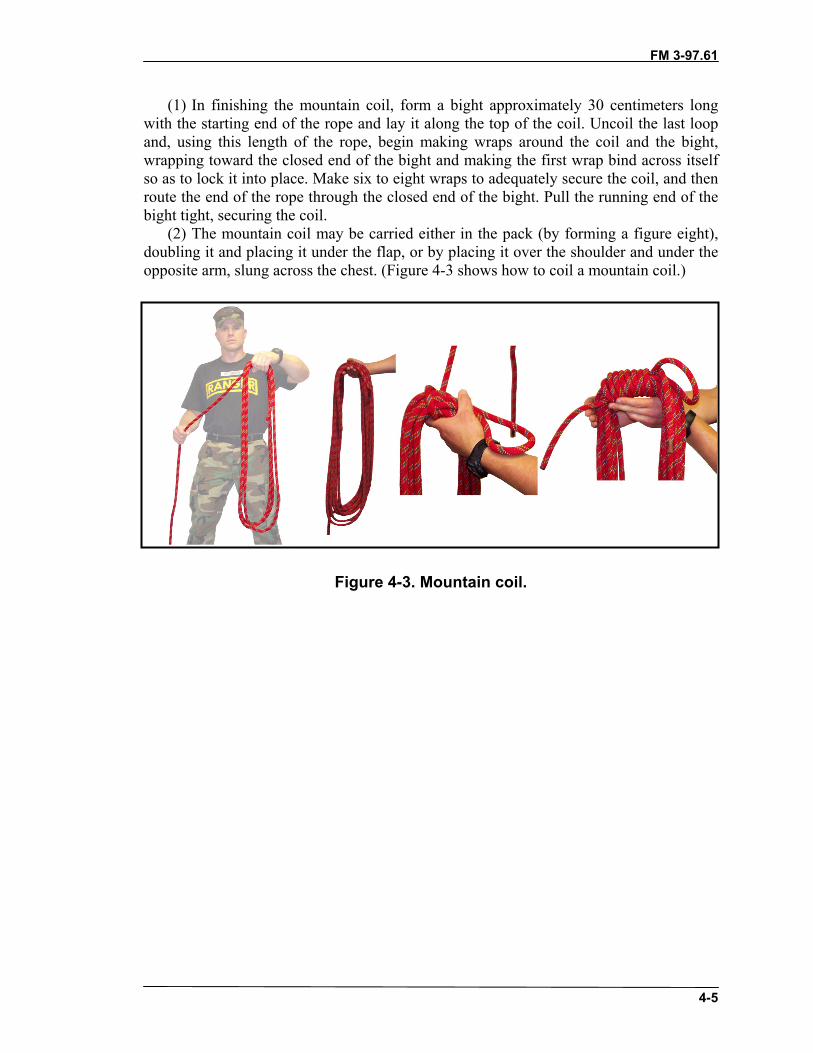
FM 3-97.61
4-5
(1) In finishing the mountain coil, form a bight approximately 30 centimeters longwith the starting end of the rope and lay it along the top of the coil. Uncoil the last loopand, using this length of the rope, begin making wraps around the coil and the bight,wrapping toward the closed end of the bight and making the first wrap bind across itselfso as to lock it into place. Make six to eight wraps to adequately secure the coil, and thenroute the end of the rope through the closed end of the bight. Pull the running end of thebight tight, securing the coil.
(2) The mountain coil may be carried either in the pack (by forming a figure eight),doubling it and placing it under the flap, or by placing it over the shoulder and under theopposite arm, slung across the chest. (Figure 4-3 shows how to coil a mountain coil.)
Figure 4-3. Mountain coil.
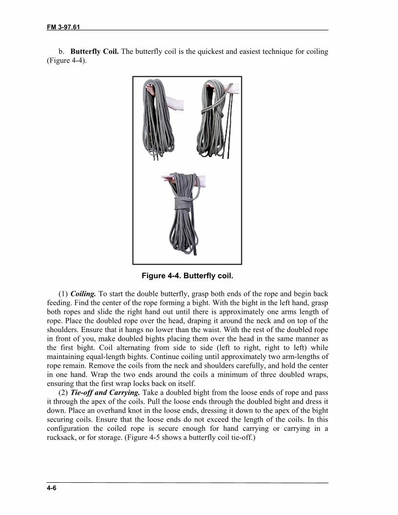
FM 3-97.61
4-6
b. Butterfly Coil. The butterfly coil is the quickest and easiest technique for coiling(Figure 4-4).
Figure 4-4. Butterfly coil.
(1) Coiling. To start the double butterfly, grasp both ends of the rope and begin backfeeding. Find the center of the rope forming a bight. With the bight in the left hand, graspboth ropes and slide the right hand out until there is approximately one arms length ofrope. Place the doubled rope over the head, draping it around the neck and on top of theshoulders. Ensure that it hangs no lower than the waist. With the rest of the doubled ropein front of you, make doubled bights placing them over the head in the same manner asthe first bight. Coil alternating from side to side (left to right, right to left) whilemaintaining equal-length bights. Continue coiling until approximately two arm-lengths ofrope remain. Remove the coils from the neck and shoulders carefully, and hold the centerin one hand. Wrap the two ends around the coils a minimum of three doubled wraps,ensuring that the first wrap locks back on itself.
(2) Tie-off and Carrying. Take a doubled bight from the loose ends of rope and passit through the apex of the coils. Pull the loose ends through the doubled bight and dress itdown. Place an overhand knot in the loose ends, dressing it down to the apex of the bightsecuring coils. Ensure that the loose ends do not exceed the length of the coils. In thisconfiguration the coiled rope is secure enough for hand carrying or carrying in arucksack, or for storage. (Figure 4-5 shows a butterfly coil tie-off.)

FM 3-97.61
4-7
Figure 4-5. Butterfly coil tie-off.
c. Coiling Smaller Diameter Rope. Ropes of smaller diameters may be coiledusing the butterfly or mountain coil depending on the length of the rope. Pieces 25 feetand shorter (also known as cordage, sling rope, utility cord) may be coiled so that theycan be hung from the harness. Bring the two ends of the rope together, ensuring no kinksare in the rope. Place the ends of the rope in the left hand with the two ends facing thebody. Coil the doubled rope in a clockwise direction forming 6- to 8-inch coils (coils maybe larger depending on the length of rope) until an approximate 12-inch bight is left.Wrap that bight around the coil, ensuring that the first wrap locks on itself. Make three ormore wraps. Feed the bight up through the bights formed at the top of the coil. Dress itdown tightly. Now the piece of rope may be hung from a carabiner on the harness.
e. Uncoiling, Back-feeding, and Stacking. When the rope is needed for use, it mustbe uncoiled and stacked on the ground properly to avoid kinks and snarls.
(1) Untie the tie-off and lay the coil on the ground. Back-feed the rope to minimizekinks and snarls. (This is also useful when the rope is to be moved a short distance and
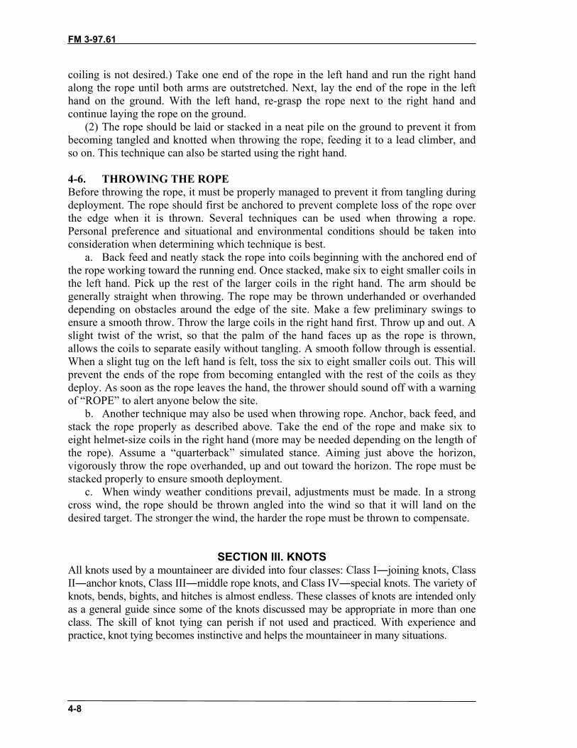
FM 3-97.61
4-8
coiling is not desired.) Take one end of the rope in the left hand and run the right handalong the rope until both arms are outstretched. Next, lay the end of the rope in the lefthand on the ground. With the left hand, re-grasp the rope next to the right hand andcontinue laying the rope on the ground.
(2) The rope should be laid or stacked in a neat pile on the ground to prevent it frombecoming tangled and knotted when throwing the rope, feeding it to a lead climber, andso on. This technique can also be started using the right hand.
4-6. THROWING THE ROPEBefore throwing the rope, it must be properly managed to prevent it from tangling duringdeployment. The rope should first be anchored to prevent complete loss of the rope overthe edge when it is thrown. Several techniques can be used when throwing a rope.Personal preference and situational and environmental conditions should be taken intoconsideration when determining which technique is best.
a. Back feed and neatly stack the rope into coils beginning with the anchored end ofthe rope working toward the running end. Once stacked, make six to eight smaller coils inthe left hand. Pick up the rest of the larger coils in the right hand. The arm should begenerally straight when throwing. The rope may be thrown underhanded or overhandeddepending on obstacles around the edge of the site. Make a few preliminary swings toensure a smooth throw. Throw the large coils in the right hand first. Throw up and out. Aslight twist of the wrist, so that the palm of the hand faces up as the rope is thrown,allows the coils to separate easily without tangling. A smooth follow through is essential.When a slight tug on the left hand is felt, toss the six to eight smaller coils out. This willprevent the ends of the rope from becoming entangled with the rest of the coils as theydeploy. As soon as the rope leaves the hand, the thrower should sound off with a warningof “ROPE” to alert anyone below the site.
b. Another technique may also be used when throwing rope. Anchor, back feed, andstack the rope properly as described above. Take the end of the rope and make six toeight helmet-size coils in the right hand (more may be needed depending on the length ofthe rope). Assume a “quarterback” simulated stance. Aiming just above the horizon,vigorously throw the rope overhanded, up and out toward the horizon. The rope must bestacked properly to ensure smooth deployment.
c. When windy weather conditions prevail, adjustments must be made. In a strongcross wind, the rope should be thrown angled into the wind so that it will land on thedesired target. The stronger the wind, the harder the rope must be thrown to compensate.
SECTION III. KNOTSAll knots used by a mountaineer are divided into four classes: Class I―joining knots, ClassII―anchor knots, Class III―middle rope knots, and Class IV―special knots. The variety ofknots, bends, bights, and hitches is almost endless. These classes of knots are intended onlyas a general guide since some of the knots discussed may be appropriate in more than oneclass. The skill of knot tying can perish if not used and practiced. With experience andpractice, knot tying becomes instinctive and helps the mountaineer in many situations.

FM 3-97.61
4-9
4-7. SQUARE KNOTThe square knot is used to tie the ends of two ropes of equal diameter (Figure 4-6). It is ajoining knot.
a. Tying the Knot.STEP 1. Holding one working end in each hand, place the working end in the
right hand over the one in the left hand.STEP 2. Pull it under and back over the top of the rope in the left hand.STEP 3. Place the working end in the left hand over the one in the right hand and
repeat STEP 2.STEP 4. Dress the knot down and secure it with an overhand knot on each side of
the square knot.
Figure 4-6. Square knot.
b. Checkpoints.(1) There are two interlocking bights.(2) The running end and standing part are on the same side of the bight formed by the
other rope. (3) The running ends are parallel to and on the same side of the standing ends with
4-inch minimum pig tails after the overhand safeties are tied.
4-8. FISHERMAN’S KNOTThe fisherman’s knot is used to tie two ropes of the same or approximately the samediameter (Figure 4-7, page 4-10). It is a joining knot.
a. Tying the Knot.STEP 1. Tie an overhand knot in one end of the rope.

FM 3-97.61
4-10
STEP 2. Pass the working end of the other rope through the first overhand knot.Tie an overhand knot around the standing part of the first rope with theworking end of the second rope.
STEP 3. Tightly dress down each overhand knot and tightly draw the knotstogether.
Figure 4-7. Fisherman’s knot.
b. Checkpoints.(1) The two separate overhand knots are tied tightly around the long, standing part of the
opposing rope.(2) The two overhand knots are drawn snug.(3) Ends of rope exit knot opposite each other with 4-inch pigtails.
4-9. DOUBLE FISHERMAN’S KNOTThe double fisherman’s knot (also called double English or grapevine) is used to tie tworopes of the same or approximately the same diameter (Figure 4-8). It is a joining knot.
a. Tying the Knot.STEP 1. With the working end of one rope, tie two wraps around the standing part
of another rope.STEP 2. Insert the working end (STEP 1) back through the two wraps and draw it
tight.STEP 3. With the working end of the other rope, which contains the standing part
(STEPS 1 and 2), tie two wraps around the standing part of the other
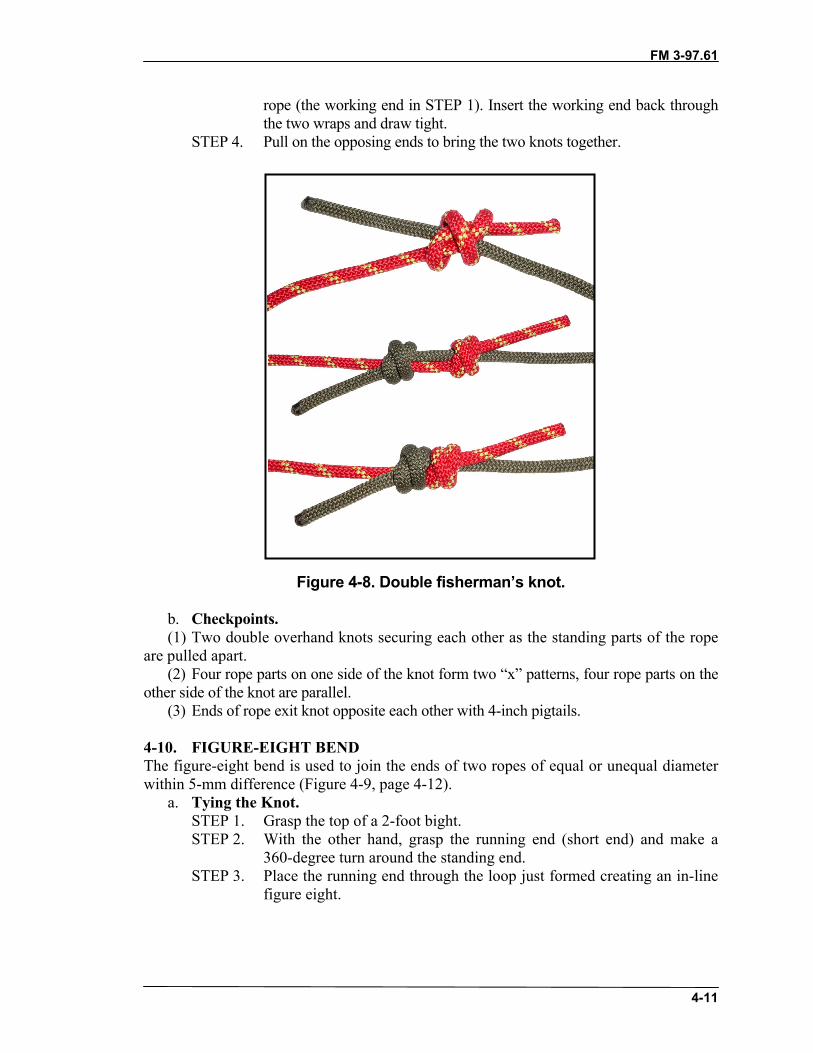
FM 3-97.61
4-11
rope (the working end in STEP 1). Insert the working end back throughthe two wraps and draw tight.
STEP 4. Pull on the opposing ends to bring the two knots together.
Figure 4-8. Double fisherman’s knot.
b. Checkpoints.(1) Two double overhand knots securing each other as the standing parts of the rope
are pulled apart.(2) Four rope parts on one side of the knot form two “x” patterns, four rope parts on the
other side of the knot are parallel.(3) Ends of rope exit knot opposite each other with 4-inch pigtails.
4-10. FIGURE-EIGHT BENDThe figure-eight bend is used to join the ends of two ropes of equal or unequal diameterwithin 5-mm difference (Figure 4-9, page 4-12).
a. Tying the Knot.STEP 1. Grasp the top of a 2-foot bight.STEP 2. With the other hand, grasp the running end (short end) and make a
360-degree turn around the standing end.STEP 3. Place the running end through the loop just formed creating an in-line
figure eight.
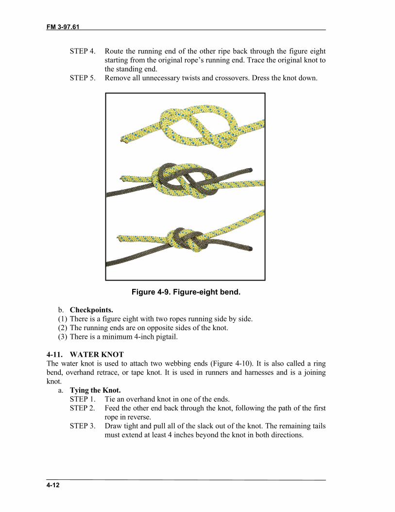
FM 3-97.61
4-12
STEP 4. Route the running end of the other ripe back through the figure eightstarting from the original rope’s running end. Trace the original knot tothe standing end.
STEP 5. Remove all unnecessary twists and crossovers. Dress the knot down.
Figure 4-9. Figure-eight bend.
b. Checkpoints.(1) There is a figure eight with two ropes running side by side.(2) The running ends are on opposite sides of the knot.(3) There is a minimum 4-inch pigtail.
4-11. WATER KNOTThe water knot is used to attach two webbing ends (Figure 4-10). It is also called a ringbend, overhand retrace, or tape knot. It is used in runners and harnesses and is a joiningknot.
a. Tying the Knot.STEP 1. Tie an overhand knot in one of the ends.STEP 2. Feed the other end back through the knot, following the path of the first
rope in reverse.STEP 3. Draw tight and pull all of the slack out of the knot. The remaining tails
must extend at least 4 inches beyond the knot in both directions.
FM 3-97.61
4-13
Figure 4-10. Water knot.
b. Checkpoints.(1) There are two overhand knots, one retracing the other.(2) There is no slack in the knot, and the working ends come out of the knot in
opposite directions.(3) There is a minimum 4-inch pigtail.
4-12. BOWLINEThe bowline is used to tie the end of a rope around an anchor. It may also be used to tie asingle fixed loop in the end of a rope (Figure 4-11, page 4-14). It is an anchor knot.
a. Tying the Knot.STEP 1. Bring the working end of the rope around the anchor, from right to left
(as the climber faces the anchor).STEP 2. Form an overhand loop in the standing part of the rope (on the
climber’s right) toward the anchor.STEP 3. Reach through the loop and pull up a bight.STEP 4. Place the working end of the rope (on the climber’s left) through the
bight, and bring it back onto itself. Now dress the knot down.STEP 5. Form an overhand knot with the tail from the bight.
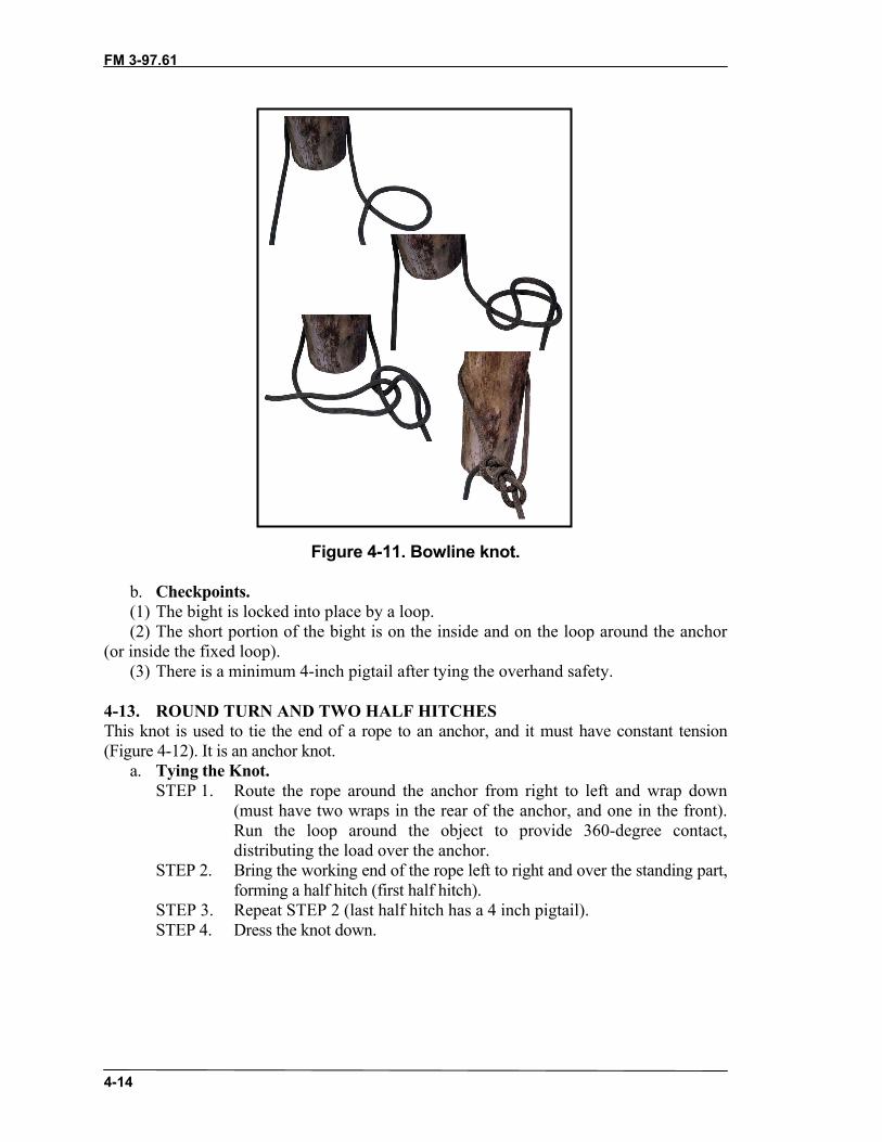
FM 3-97.61
4-14
Figure 4-11. Bowline knot.
b. Checkpoints.(1) The bight is locked into place by a loop. (2) The short portion of the bight is on the inside and on the loop around the anchor
(or inside the fixed loop).(3) There is a minimum 4-inch pigtail after tying the overhand safety.
4-13. ROUND TURN AND TWO HALF HITCHESThis knot is used to tie the end of a rope to an anchor, and it must have constant tension(Figure 4-12). It is an anchor knot.
a. Tying the Knot.STEP 1. Route the rope around the anchor from right to left and wrap down
(must have two wraps in the rear of the anchor, and one in the front).Run the loop around the object to provide 360-degree contact,distributing the load over the anchor.
STEP 2. Bring the working end of the rope left to right and over the standing part,forming a half hitch (first half hitch).
STEP 3. Repeat STEP 2 (last half hitch has a 4 inch pigtail).STEP 4. Dress the knot down.

FM 3-97.61
4-15
Figure 4-12. Round turn and two half hitches.
b. Checkpoints.(1) A complete round turn should exist around the anchor with no crosses.(2) Two half hitches should be held in place by a diagonal locking bar with no less
than a 4-inch pigtail remaining.
4-14. FIGURE-EIGHT RETRACE (REROUTED FIGURE-EIGHT)The figure-eight retrace knot produces the same result as a figure-eight loop. However, bytying the knot in a retrace, it can be used to fasten the rope to trees or to places where theloop cannot be used (Figure 4-13, page 4-16). It is also called a rerouted figure-eight and isan anchor knot.
a. Tying the Knot.STEP 1. Use a length of rope long enough to go around the anchor, leaving
enough rope to work with.STEP 2. Tie a figure-eight knot in the standing part of the rope, leaving enough
rope to go around the anchor. To tie a figure-eight knot form a loop inthe rope, wrap the working end around the standing part, and route theworking end through the loop. The finished knot is dressed loosely.
STEP 3. Take the working end around the anchor point.STEP 4. With the working end, insert the rope back through the loop of the knot
in reverse.STEP 5. Keep the original figure eight as the outside rope and retrace the knot
around the wrap and back to the long-standing part.STEP 6. Remove all unnecessary twists and crossovers; dress the knot down.
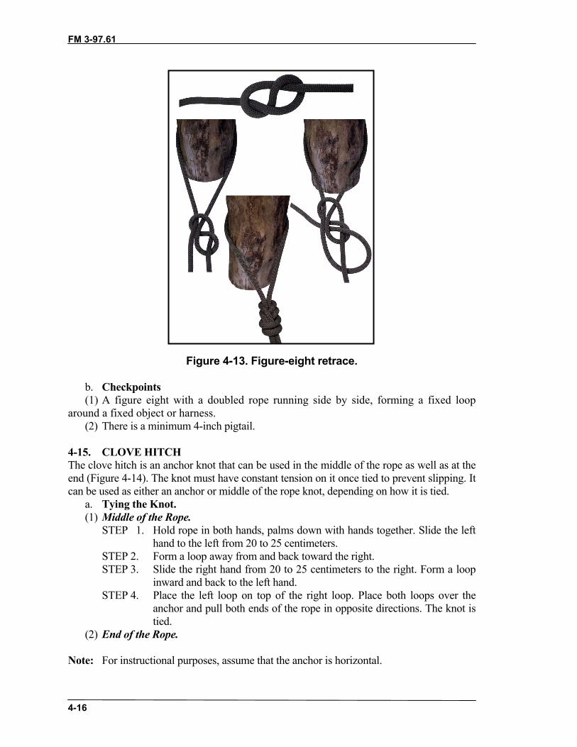
FM 3-97.61
4-16
Figure 4-13. Figure-eight retrace.
b. Checkpoints(1) A figure eight with a doubled rope running side by side, forming a fixed loop
around a fixed object or harness.(2) There is a minimum 4-inch pigtail.
4-15. CLOVE HITCHThe clove hitch is an anchor knot that can be used in the middle of the rope as well as at theend (Figure 4-14). The knot must have constant tension on it once tied to prevent slipping. Itcan be used as either an anchor or middle of the rope knot, depending on how it is tied.
a. Tying the Knot.(1) Middle of the Rope.
STEP 1. Hold rope in both hands, palms down with hands together. Slide the lefthand to the left from 20 to 25 centimeters.
STEP 2. Form a loop away from and back toward the right.STEP 3. Slide the right hand from 20 to 25 centimeters to the right. Form a loop
inward and back to the left hand.STEP 4. Place the left loop on top of the right loop. Place both loops over the
anchor and pull both ends of the rope in opposite directions. The knot istied.
(2) End of the Rope.
Note: For instructional purposes, assume that the anchor is horizontal.

FM 3-97.61
4-17
STEP 1. Place 76 centimeters of rope over the top of the anchor. Hold thestanding end in the left hand. With the right hand, reach under thehorizontal anchor, grasp the working end, and bring it inward.
STEP 2. Place the working end of the rope over the standing end (to form a loop).Hold the loop in the left hand. Place the working end over the anchorfrom 20 to 25 centimeters to the left of the loop.
STEP 3. With the right hand, reach down to the left hand side of the loop underthe anchor. Grasp the working end of the rope. Bring the working end upand outward.
STEP 4. Dress down the knot.
Figure 4-14. Clove hitch.
b. Checkpoints.(1) The knot has two round turns around the anchor with a diagonal locking bar.(2) The locking bar is facing 90 degrees from the direction of pull.(3) The ends exit l80 degrees from each other.(4) The knot has more than a 4-inch pigtail remaining.
4-16. WIREMAN’S KNOTThe wireman’s knot forms a single, fixed loop in the middle of the rope (Figure 4-15, page4-18). It is a middle rope knot.
a. Tying the Knot.STEP 1. When tying this knot, face the anchor that the tie-off system will be tied
to. Take up the slack from the anchor, and wrap two turns around the lefthand (palm up) from left to right.
STEP 2. A loop of 30 centimeters is taken up in the second round turn to createthe fixed loop of the knot.
STEP 3. Name the wraps from the palm to the fingertips: heel, palm, andfingertip.
STEP 4. Secure the palm wrap with the right thumb and forefinger, and place itover the heel wrap.
STEP 5. Secure the heel wrap and place it over the fingertip wrap.STEP 6. Secure the fingertip wrap and place it over the palm wrap.STEP 7. Secure the palm wrap and pull up to form a fixed loop.

FM 3-97.61
4-18
STEP 8. Dress the knot down by pulling on the fixed loop and the two workingends.
STEP 9. Pull the working ends apart to finish the knot.
Figure 4-15. Wireman’s knot.
b. Checkpoints.(1) The completed knot should have four separate bights locking down on themselves
with the fixed loop exiting from the top of the knot and laying toward the near side anchorpoint.
(2) Both ends should exit opposite each other without any bends.
4-17. DIRECTIONAL FIGURE-EIGHTThe directional figure-eight knot forms a single, fixed loop in the middle of the rope thatlays back along the standing part of the rope (Figure 4-16). It is a middle rope knot.
a. Tying the Knot.STEP 1. Face the far side anchor so that when the knot is tied, it lays inward.STEP 2. Lay the rope from the far side anchor over the left palm. Make one wrap
around the palm.STEP 3. With the wrap thus formed, tie a figure-eight knot around the standing
part that leads to the far side anchor.STEP 4. When dressing the knot down, the tail and the bight must be together.
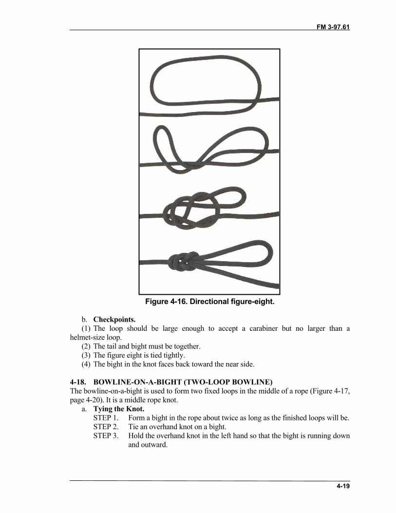
FM 3-97.61
4-19
Figure 4-16. Directional figure-eight.
b. Checkpoints.(1) The loop should be large enough to accept a carabiner but no larger than a
helmet-size loop. (2) The tail and bight must be together.(3) The figure eight is tied tightly. (4) The bight in the knot faces back toward the near side.
4-18. BOWLINE-ON-A-BIGHT (TWO-LOOP BOWLINE)The bowline-on-a-bight is used to form two fixed loops in the middle of a rope (Figure 4-17,page 4-20). It is a middle rope knot.
a. Tying the Knot.STEP 1. Form a bight in the rope about twice as long as the finished loops will be.STEP 2. Tie an overhand knot on a bight.STEP 3. Hold the overhand knot in the left hand so that the bight is running down
and outward.

FM 3-97.61
4-20
STEP 4. Grasp the bight with the right hand; fold it back over the overhand knotso that the overhand knot goes through the bight.
STEP 5. From the end (apex) of the bight, follow the bight back to where it formsthe cross in the overhand knot. Grasp the two ropes that run down andoutward and pull up, forming two loops.
STEP 6. Pull the two ropes out of the overhand knot and dress the knot down.STEP 7. A final dress is required: grasp the ends of the two fixed loops and pull,
spreading them apart to ensure the loops do not slip.
Figure 4-17. Bowline-on-a-bight.
b. Checkpoints.(1) There are two fixed loops that will not slip. (2) There are no twists in the knot.(3) A double loop is held in place by a bight.
4-19. TWO-LOOP FIGURE-EIGHTThe two-loop figure-eight is used to form two fixed loops in the middle of a rope (Figure4-18.) It is a middle rope knot.
a. Tying the Knot.STEP 1. Using a doubled rope, form an 18-inch bight in the left hand with the
running end facing to the left.STEP 2. Grasp the bight with the right hand and make a 360-degree turn around
the standing end in a counterclockwise direction.

FM 3-97.61
4-21
STEP 3. With the working end, form another bight and place that bight throughthe loop just formed in the left hand.
STEP 4. Hold the bight with the left hand, and place the original bight (movingtoward the left hand) over the knot.
STEP 5. Dress the knot down.
Figure 4-18. Two-loop figure-eight.
b. Checkpoints.(1) There is a double figure-eight knot with two loops that share a common locking bar. (2) The two loops must be adjustable by means of a common locking bar.(3) The common locking bar is on the bottom of the double figure-eight knot.
4-20. FIGURE-EIGHT LOOP (FIGURE-EIGHT-ON-A-BIGHT)The figure-eight loop, also called the figure-eight-on-a-bight, is used to form a fixed loop ina rope (Figure 4-19). It is a middle of the rope knot.
a. Tying the Knot.STEP 1. Form a bight in the rope about as large as the diameter of the desired
loop.STEP 2. With the bight as the working end, form a loop in rope (standing part).STEP 3. Wrap the working end around the standing part 360 degrees and feed the
working end through the loop. Dress the knot tightly.
Figure 4-19. Figure-eight loop.
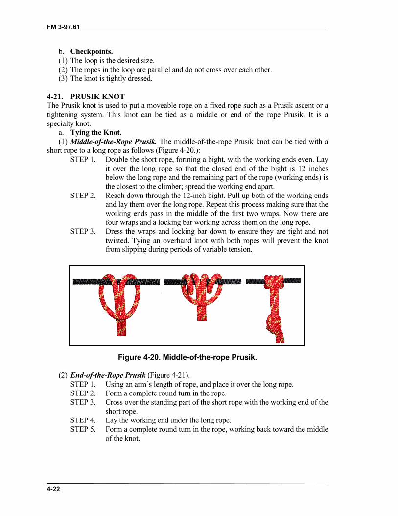
FM 3-97.61
4-22
b. Checkpoints.(1) The loop is the desired size.(2) The ropes in the loop are parallel and do not cross over each other.(3) The knot is tightly dressed.
4-21. PRUSIK KNOTThe Prusik knot is used to put a moveable rope on a fixed rope such as a Prusik ascent or atightening system. This knot can be tied as a middle or end of the rope Prusik. It is aspecialty knot.
a. Tying the Knot.(1) Middle-of-the-Rope Prusik. The middle-of-the-rope Prusik knot can be tied with a
short rope to a long rope as follows (Figure 4-20.):STEP 1. Double the short rope, forming a bight, with the working ends even. Lay
it over the long rope so that the closed end of the bight is 12 inchesbelow the long rope and the remaining part of the rope (working ends) isthe closest to the climber; spread the working end apart.
STEP 2. Reach down through the 12-inch bight. Pull up both of the working endsand lay them over the long rope. Repeat this process making sure that theworking ends pass in the middle of the first two wraps. Now there arefour wraps and a locking bar working across them on the long rope.
STEP 3. Dress the wraps and locking bar down to ensure they are tight and nottwisted. Tying an overhand knot with both ropes will prevent the knotfrom slipping during periods of variable tension.
Figure 4-20. Middle-of-the-rope Prusik.
(2) End-of-the-Rope Prusik (Figure 4-21).STEP 1. Using an arm’s length of rope, and place it over the long rope.STEP 2. Form a complete round turn in the rope.STEP 3. Cross over the standing part of the short rope with the working end of the
short rope.STEP 4. Lay the working end under the long rope.STEP 5. Form a complete round turn in the rope, working back toward the middle
of the knot.

FM 3-97.61
4-23
STEP 6. There are four wraps and a locking bar running across them on the longrope. Dress the wraps and locking bar down. Ensure they are tight,parallel, and not twisted.
STEP 7. Finish the knot with a bowline to ensure that the Prusik knot will not slipout during periods of varying tension.
Figure 4-21. End-of-the-rope Prusik knot.
b. Checkpoints.(1) Four wraps with a locking bar.(2) The locking bar faces the climber.(3) The knot is tight and dressed down with no ropes twisted or crossed.(4) Other than a finger Prusik, the knot should contain an overhand or bowline to
prevent slipping.
4-22. BACHMAN KNOTThe Bachman knot provides a means of using a makeshift mechanized ascender (Figure4-22, page 4-24). It is a specialty knot.
a. Tying the Knot.STEP 1. Find the middle of a utility rope and insert it into a carabiner.STEP 2. Place the carabiner and utility rope next to a long climbing rope.STEP 3. With the two ropes parallel from the carabiner, make two or more wraps
around the climbing rope and through the inside portion of the carabiner.
Note: The rope can be tied into an etrier (stirrup) and used as a Prusik-friction principleascender.
b. Checkpoints.(1) The bight of the climbing rope is at the top of the carabiner.(2) The two ropes run parallel without twisting or crossing.(3) Two or more wraps are made around the long climbing rope and through the inside
portion of the carabiner.

FM 3-97.61
4-24
Figure 4-22. Bachman knot.
4-23. BOWLINE-ON-A-COILThe bowline-on-a-coil is an expedient tie-in used by climbers when a climbing harness isnot available (Figure 4-23). It is a specialty knot.
a. Tying the Knot.STEP 1. With the running end, place 3 feet of rope over your right shoulder. The
running end is to the back of the body.STEP 2. Starting at the bottom of your rib cage, wrap the standing part of the
rope around your body and down in a clockwise direction four to eighttimes.
STEP 3. With the standing portion of the rope in your left hand, make a clockwiseloop toward the body. The standing portion is on the bottom.
STEP 4. Ensuring the loop does not come uncrossed, bring it up and under thecoils between the rope and your body.
STEP 5. Using the standing part, bring a bight up through the loop. Grasp therunning end of the rope with the right hand. Pass it through the bightfrom right to left and back on itself.
STEP 6. Holding the bight loosely, dress the knot down by pulling on thestanding end.
STEP 7. Safety the bowline with an overhand around the top, single coil. Then, tiean overhand around all coils, leaving a minimum 4-inch pigtail.
b. Checkpoints.(1) A minimum of four wraps, not crossed, with a bight held in place by a loop. (2) The loop must be underneath all wraps.(3) A minimum 4-inch pigtail after the second overhand safety is tied.(4) Must be centered on the mid-line of the body.

FM 3-97.61
4-25
Figure 4-23. Bowline-on-a-coil.
4-24. THREE-LOOP BOWLINEThe three-loop bowline is used to form three fixed loops in the middle of a rope (Figure4-24, page 4-26). It is used in a self-equalizing anchor system. It is a specialty knot.
a. Tying the Knot.STEP 1. Form an approximate 24-inch bight.STEP 2. With the right thumb facing toward the body, form a doubled loop in the
standing part by turning the wrist clockwise. Lay the loops to the right.STEP 3. With the right hand, reach down through the loops and pull up a doubled
bight from the standing part of the rope.STEP 4. Place the running end (bight) of the rope (on the left) through the
doubled bight from left to right and bring it back on itself. Hold therunning end loosely and dress the knot down by pulling on the standingparts.
STEP 5. Safety it off with a doubled overhand knot.

FM 3-97.61
4-26
Figure 4-24. Three-loop bowline.
b. Checkpoints.(1) There are two bights held in place by two loops. (2) The bights form locking bars around the standing parts.(3) The running end (bight) must be on the inside of the fixed loops.(4) There is a minimum 4-inch pigtail after the double overhand safety knot is tied.
4-25. FIGURE-EIGHT SLIP KNOTThe figure eight slip knot forms an adjustable bight in a rope (Figure 4-25). It is aspecialty knot.
a. Tying the Knot.STEP 1. Form a 12-inch bight in the end of the rope.STEP 2. Hold the center of the bight in the right hand. Hold the two parallel ropes
from the bight in the left hand about 12 inches up the rope.STEP 3. With the center of the bight in the right hand, twist two complete turns
clockwise.STEP 4. Reach through the bight and grasp the long, standing end of the rope.
Pull another bight (from the long standing end) back through the original bight.STEP 5. Pull down on the short working end of the rope and dress the knot down.STEP 6. If the knot is to be used in a transport tightening system, take the
working end of the rope and form a half hitch around the loop of the figure eight knot.
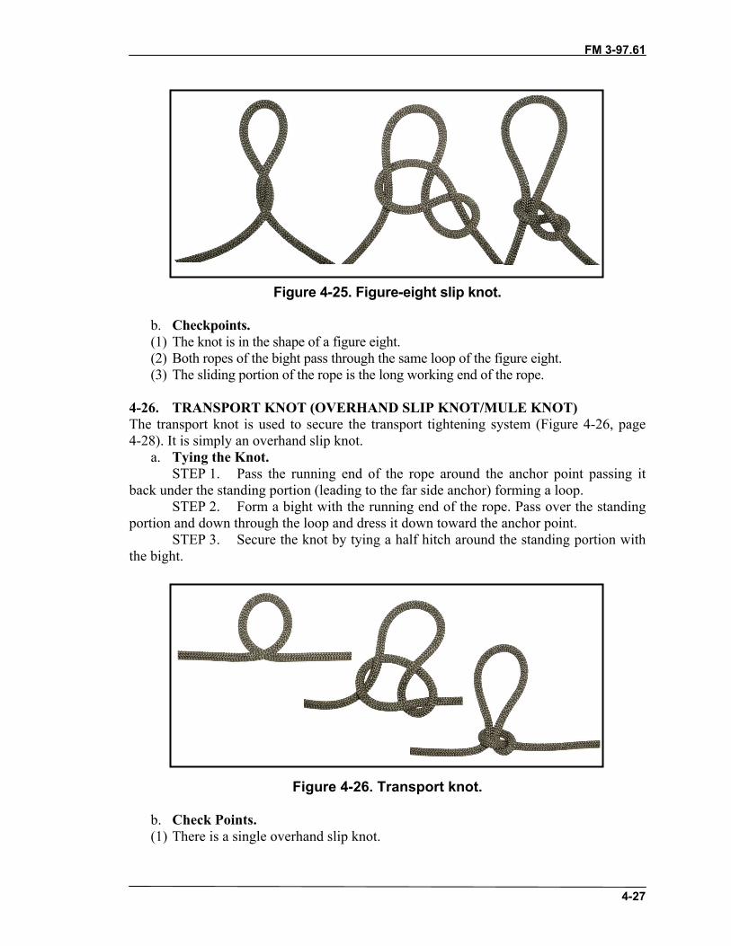
FM 3-97.61
4-27
Figure 4-25. Figure-eight slip knot.
b. Checkpoints.(1) The knot is in the shape of a figure eight.(2) Both ropes of the bight pass through the same loop of the figure eight.(3) The sliding portion of the rope is the long working end of the rope.
4-26. TRANSPORT KNOT (OVERHAND SLIP KNOT/MULE KNOT)The transport knot is used to secure the transport tightening system (Figure 4-26, page4-28). It is simply an overhand slip knot.
a. Tying the Knot.STEP 1. Pass the running end of the rope around the anchor point passing it
back under the standing portion (leading to the far side anchor) forming a loop.STEP 2. Form a bight with the running end of the rope. Pass over the standing
portion and down through the loop and dress it down toward the anchor point.STEP 3. Secure the knot by tying a half hitch around the standing portion with
the bight.
Figure 4-26. Transport knot.
b. Check Points.(1) There is a single overhand slip knot.
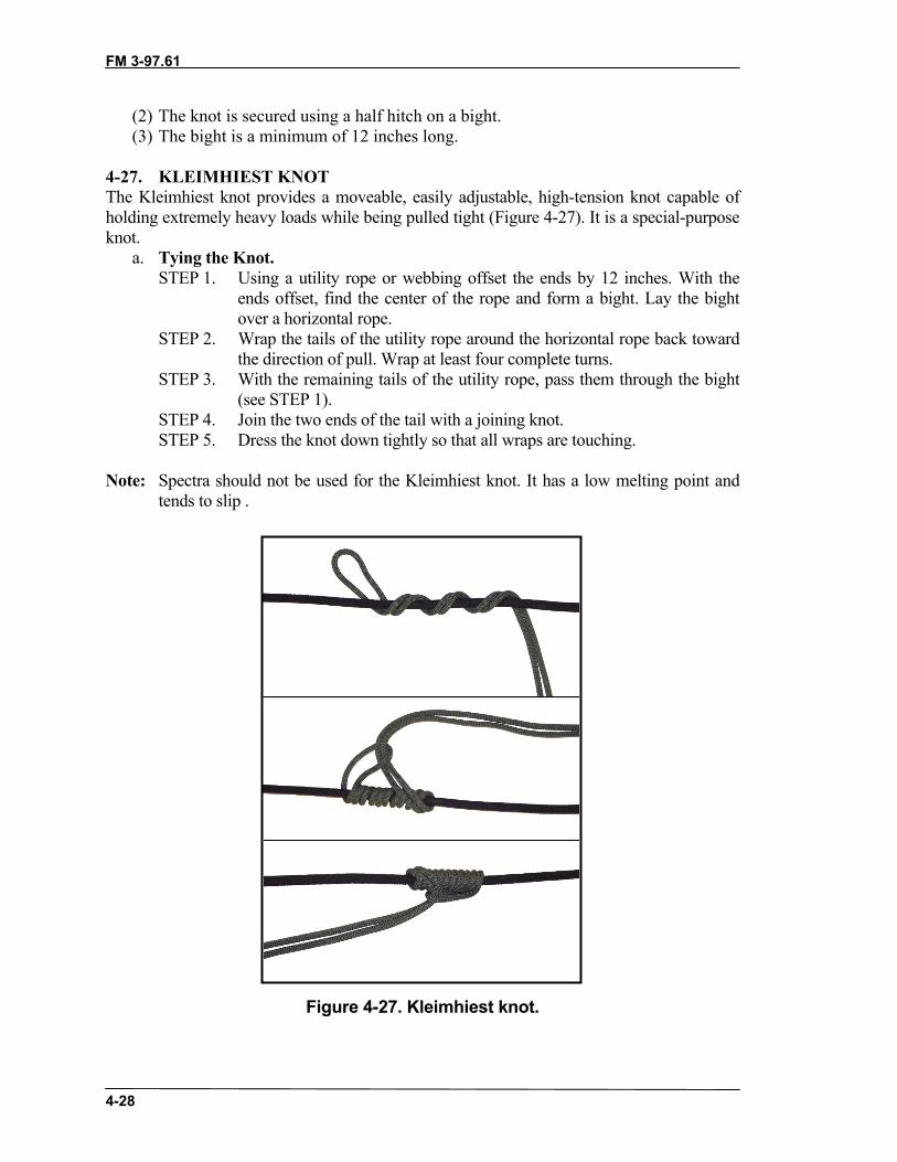
FM 3-97.61
4-28
(2) The knot is secured using a half hitch on a bight.(3) The bight is a minimum of 12 inches long.
4-27. KLEIMHIEST KNOT The Kleimhiest knot provides a moveable, easily adjustable, high-tension knot capable ofholding extremely heavy loads while being pulled tight (Figure 4-27). It is a special-purposeknot.
a. Tying the Knot.STEP 1. Using a utility rope or webbing offset the ends by 12 inches. With the
ends offset, find the center of the rope and form a bight. Lay the bightover a horizontal rope.
STEP 2. Wrap the tails of the utility rope around the horizontal rope back towardthe direction of pull. Wrap at least four complete turns.
STEP 3. With the remaining tails of the utility rope, pass them through the bight(see STEP 1).
STEP 4. Join the two ends of the tail with a joining knot.STEP 5. Dress the knot down tightly so that all wraps are touching.
Note: Spectra should not be used for the Kleimhiest knot. It has a low melting point andtends to slip .
Figure 4-27. Kleimhiest knot.

FM 3-97.61
4-29
b. Checkpoints.(1) The bight is opposite the direction of pull. (2) All wraps are tight and touching. (3) The ends of the utility rope are properly secured with a joining knot.
4-28. FROST KNOTThe frost knot is used when working with webbing (Figure 4-28, page 4-30). It is used tocreate the top loop of an etrier. It is a special-purpose knot.
a. Tying the Knot.STEP 1. Lap one end (a bight) of webbing over the other about 10 to 12 inches.STEP 2. Tie an overhand knot with the newly formed triple-strand webbing; dress
tightly.
Figure 4-28. Frost knot.
b. Checkpoints.(1) The tails of the webbing run in opposite directions.(2) Three strands of webbing are formed into a tight overhand knot.(3) There is a bight and tail exiting the top of the overhand knot.

FM 3-97.61
4-30
4-29. GIRTH HITCHThe girth hitch is used to attach a runner to an anchor or piece of equipment (Figure 4-29). Itis a special-purpose knot.
a. Tying the Knot.STEP 1: Form a bight.STEP 2: Bring the runner back through the bight.STEP 3: Cinch the knot tightly.
Figure 4-29. Girth hitch.
b. Checkpoint.(1) Two wraps exist with a locking bar running across the wraps.(2) The knot is dressed tightly.
4-30. MUNTER HITCHThe munter hitch, when used in conjunction with a pear-shaped locking carabiner, is usedto form a mechanical belay (Figure 4-30).
a. Tying the Knot.STEP 1. Hold the rope in both hands, palms down about 12 inches apart.STEP 2. With the right hand, form a loop away from the body toward the left
hand. Hold the loop with the left hand.STEP 3. With the right hand, place the rope that comes from the bottom of the
loop over the top of the loop.STEP 4. Place the bight that has just been formed around the rope into the pear
shaped carabiner. Lock the locking mechanism.b. Check Points.(1) A bight passes through the carabiner, with the closed end around the standing or
running part of the rope.(2) The carabiner is locked.
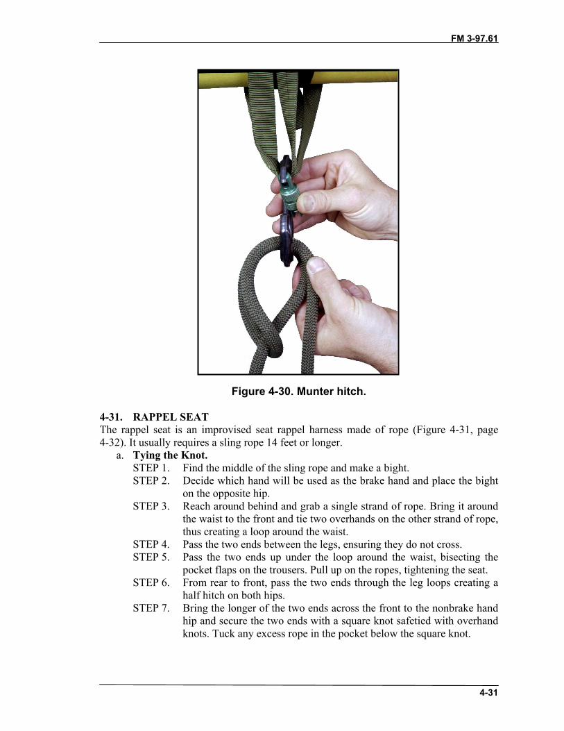
FM 3-97.61
4-31
Figure 4-30. Munter hitch.
4-31. RAPPEL SEATThe rappel seat is an improvised seat rappel harness made of rope (Figure 4-31, page4-32). It usually requires a sling rope 14 feet or longer.
a. Tying the Knot.STEP 1. Find the middle of the sling rope and make a bight.STEP 2. Decide which hand will be used as the brake hand and place the bight
on the opposite hip.STEP 3. Reach around behind and grab a single strand of rope. Bring it around
the waist to the front and tie two overhands on the other strand of rope,thus creating a loop around the waist.
STEP 4. Pass the two ends between the legs, ensuring they do not cross.STEP 5. Pass the two ends up under the loop around the waist, bisecting the
pocket flaps on the trousers. Pull up on the ropes, tightening the seat.STEP 6. From rear to front, pass the two ends through the leg loops creating a
half hitch on both hips.STEP 7. Bring the longer of the two ends across the front to the nonbrake hand
hip and secure the two ends with a square knot safetied with overhandknots. Tuck any excess rope in the pocket below the square knot.

FM 3-97.61
4-32
Figure 4-31. Rappel seat.
b. Check Points.(1) There are two overhand knots in the front.(2) The ropes are not crossed between the legs.(3) A half hitch is formed on each hip.(4) Seat is secured with a square knot with overhand safeties on the non-brake hand
side.(5) There is a minimum 4-inch pigtail after the overhand safeties are tied.
4-32. GUARDE KNOTThe guarde knot (ratchet knot, alpine clutch) is a special purpose knot primarily used forhauling systems or rescue (Figure 4-32). The knot works in only one direction and cannotbe reversed while under load.
a. Tying the Knot.STEP 1. Place a bight of rope into the two anchored carabiners (works best with
two like carabiners, preferably ovals).
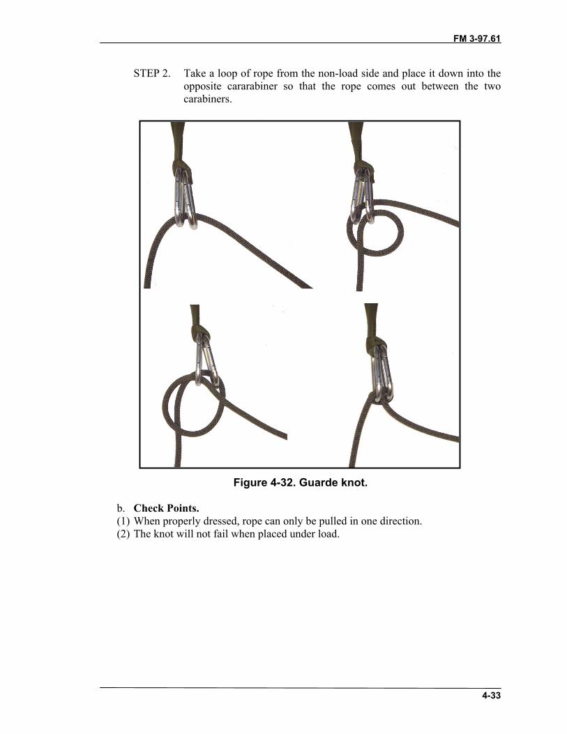
FM 3-97.61
4-33
STEP 2. Take a loop of rope from the non-load side and place it down into theopposite cararabiner so that the rope comes out between the twocarabiners.
Figure 4-32. Guarde knot.
b. Check Points.(1) When properly dressed, rope can only be pulled in one direction.(2) The knot will not fail when placed under load.
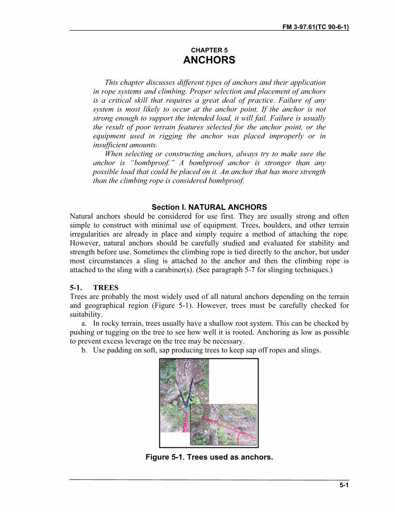
FM 3-97.61(TC 90-6-1)
5-1
CHAPTER 5ANCHORS
This chapter discusses different types of anchors and their applicationin rope systems and climbing. Proper selection and placement of anchorsis a critical skill that requires a great deal of practice. Failure of anysystem is most likely to occur at the anchor point. If the anchor is notstrong enough to support the intended load, it will fail. Failure is usuallythe result of poor terrain features selected for the anchor point, or theequipment used in rigging the anchor was placed improperly or ininsufficient amounts.
When selecting or constructing anchors, always try to make sure theanchor is “bombproof.” A bombproof anchor is stronger than anypossible load that could be placed on it. An anchor that has more strengththan the climbing rope is considered bombproof.
Section I. NATURAL ANCHORSNatural anchors should be considered for use first. They are usually strong and oftensimple to construct with minimal use of equipment. Trees, boulders, and other terrainirregularities are already in place and simply require a method of attaching the rope.However, natural anchors should be carefully studied and evaluated for stability andstrength before use. Sometimes the climbing rope is tied directly to the anchor, but undermost circumstances a sling is attached to the anchor and then the climbing rope isattached to the sling with a carabiner(s). (See paragraph 5-7 for slinging techniques.)
5-1. TREESTrees are probably the most widely used of all natural anchors depending on the terrainand geographical region (Figure 5-1). However, trees must be carefully checked forsuitability.
a. In rocky terrain, trees usually have a shallow root system. This can be checked bypushing or tugging on the tree to see how well it is rooted. Anchoring as low as possibleto prevent excess leverage on the tree may be necessary.
b. Use padding on soft, sap producing trees to keep sap off ropes and slings.
Figure 5-1. Trees used as anchors.

FM 3-97.61
5-2
5-2. BOULDERSBoulders and rock nubbins make ideal anchors (Figure 5-2). The rock can be firmlytapped with a piton hammer to ensure it is solid. Sedimentary and other loose rockformations are not stable. Talus and scree fields are an indicator that the rock in the areais not solid. All areas around the rock formation that could cut the rope or sling should bepadded.
Figure 5-2. Boulders used as anchors.
5-3. CHOCKSTONESA chockstone is a rock that is wedged in a crack because the crack narrows downward(Figure 5-3). Chockstones should be checked for strength, security, and crumbling andshould always be tested before use. All chockstones must be solid and strong enough tosupport the load. They must have maximum surface contact and be well tapered with thesurrounding rock to remain in position.
a. Chockstones are often directional―they are secure when pulled in one directionbut may pop out if pulled in another direction.
b. A creative climber can often make his own chockstone by wedging a rock intoposition, tying a rope to it, and clipping on a carabiner.
c. Slings should not be wedged between the chockstone and the rock wall since afall could cut the webbing runner.

FM 3-97.61
5-3
Figure 5-3. Chockstones.
5-4. ROCK PROJECTIONSRock projections (sometimes called nubbins) often provide suitable protection (Figure 5-4).These include blocks, flakes, horns, and spikes. If rock projections are used, their firmness isimportant. They should be checked for cracks or weathering that may impair their firmness.If any of these signs exist, the projection should be avoided.
Figure 5-4. Rock projections.

FM 3-97.61
5-4
5-5. TUNNELS AND ARCHESTunnels and arches are holes formed in solid rock and provide one of the more secureanchor points because they can be pulled in any direction. A sling is threaded through theopening hole and secured with a joining knot or girth hitch. The load-bearing hole must bestrong and free of sharp edges (pad if necessary).
5-6. BUSHES AND SHRUBSIf no other suitable anchor is available, the roots of bushes can be used by routing a ropearound the bases of several bushes (Figure 5-5). As with trees, the anchoring rope is placedas low as possible to reduce leverage on the anchor. All vegetation should be healthy andwell rooted to the ground.
Figure 5-5. Bushes and shrubs.
5-7. SLINGING TECHNIQUESThree methods are used to attach a sling to a natural anchor―drape, wrap, and girth.Whichever method is used, the knot is set off to the side where it will not interfere withnormal carabiner movement. The carabiner gate should face away from the ground andopen away from the anchor for easy insertion of the rope. When a locking carabinercannot be used, two carabiners are used with gates opposed. Correctly opposed gatesshould open on opposite sides and form an “X” when opened (Figure 5-6).

FM 3-97.61
5-5
Figure 5-6. Correctly opposed carabiners.
a. Drape. Drape the sling over the anchor (Figure 5-7). Untying the sling androuting it around the anchor and then retying is still considered a drape.
Figure 5-7. Drape.

FM 3-97.61
5-6
b. Wrap. Wrap the sling around the anchor and connect the two ends together with acarabiner(s) or knot (Figure 5-8).
Figure 5-8. Wrap.
c. Girth. Tie the sling around the anchor with a girth hitch (Figure 5-9). Although agirth hitch reduces the strength of the sling, it allows the sling to remain in position andnot slide on the anchor.
Figure 5-9. Girth.
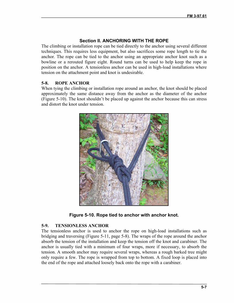
FM 3-97.61
5-7
Section II. ANCHORING WITH THE ROPEThe climbing or installation rope can be tied directly to the anchor using several differenttechniques. This requires less equipment, but also sacrifices some rope length to tie theanchor. The rope can be tied to the anchor using an appropriate anchor knot such as abowline or a rerouted figure eight. Round turns can be used to help keep the rope inposition on the anchor. A tensionless anchor can be used in high-load installations wheretension on the attachment point and knot is undesirable.
5-8. ROPE ANCHORWhen tying the climbing or installation rope around an anchor, the knot should be placedapproximately the same distance away from the anchor as the diameter of the anchor(Figure 5-10). The knot shouldn’t be placed up against the anchor because this can stressand distort the knot under tension.
Figure 5-10. Rope tied to anchor with anchor knot.
5-9. TENSIONLESS ANCHORThe tensionless anchor is used to anchor the rope on high-load installations such asbridging and traversing (Figure 5-11, page 5-8). The wraps of the rope around the anchorabsorb the tension of the installation and keep the tension off the knot and carabiner. Theanchor is usually tied with a minimum of four wraps, more if necessary, to absorb thetension. A smooth anchor may require several wraps, whereas a rough barked tree mightonly require a few. The rope is wrapped from top to bottom. A fixed loop is placed intothe end of the rope and attached loosely back onto the rope with a carabiner.

FM 3-97.61
5-8
Figure 5-11. Tensionless anchor.
Section III. ARTIFICIAL ANCHORSUsing artificial anchors becomes necessary when natural anchors are unavailable. The artof choosing and placing good anchors requires a great deal of practice and experience.Artificial anchors are available in many different types such as pitons, chocks,hexcentrics, and SLCDs. Anchor strength varies greatly; the type used depends on theterrain, equipment, and the load to be placed on it.
5-10. DEADMANA “deadman” anchor is any solid object buried in the ground and used as an anchor.
a. An object that has a large surface area and some length to it works best. (A heftytimber, such as a railroad tie, would be ideal.) Large boulders can be used, as well as abundle of smaller tree limbs or poles. As with natural anchors, ensure timbers and treelimbs are not dead or rotting and that boulders are solid. Equipment, such as skis, iceaxes, snowshoes, and ruck sacks, can also be used if necessary.
b. In extremely hard, rocky terrain (where digging a trench would be impractical, ifnot impossible) a variation of the deadman anchor can be constructed by building abovethe ground. The sling is attached to the anchor, which is set into the ground as deeply aspossible. Boulders are then stacked on top of it until the anchor is strong enough for theload. Though normally not as strong as when buried, this method can work well for light-load installations as in anchoring a hand line for a stream crossing.
Note: Artificial anchors, such as pitons and bolts, are not widely accepted for use in allareas because of the scars they leave on the rock and the environment. Often theyare left in place and become unnatural, unsightly fixtures in the naturalenvironment. For training planning, local laws and courtesies should be taken intoconsideration for each area of operation.
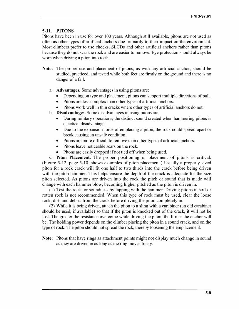
FM 3-97.61
5-9
5-11. PITONSPitons have been in use for over 100 years. Although still available, pitons are not used asoften as other types of artificial anchors due primarily to their impact on the environment.Most climbers prefer to use chocks, SLCDs and other artificial anchors rather than pitonsbecause they do not scar the rock and are easier to remove. Eye protection should always beworn when driving a piton into rock.
Note: The proper use and placement of pitons, as with any artificial anchor, should bestudied, practiced, and tested while both feet are firmly on the ground and there is nodanger of a fall.
a. Advantages. Some advantages in using pitons are:• Depending on type and placement, pitons can support multiple directions of pull.• Pitons are less complex than other types of artificial anchors.• Pitons work well in thin cracks where other types of artificial anchors do not.
b. Disadvantages. Some disadvantages in using pitons are:• During military operations, the distinct sound created when hammering pitons is
a tactical disadvantage.• Due to the expansion force of emplacing a piton, the rock could spread apart or
break causing an unsafe condition. • Pitons are more difficult to remove than other types of artificial anchors.• Pitons leave noticeable scars on the rock.• Pitons are easily dropped if not tied off when being used.
c. Piton Placement. The proper positioning or placement of pitons is critical.(Figure 5-12, page 5-10, shows examples of piton placement.) Usually a properly sizedpiton for a rock crack will fit one half to two thirds into the crack before being drivenwith the piton hammer. This helps ensure the depth of the crack is adequate for the sizepiton selected. As pitons are driven into the rock the pitch or sound that is made willchange with each hammer blow, becoming higher pitched as the piton is driven in.
(1) Test the rock for soundness by tapping with the hammer. Driving pitons in soft orrotten rock is not recommended. When this type of rock must be used, clear the looserock, dirt, and debris from the crack before driving the piton completely in.
(2) While it is being driven, attach the piton to a sling with a carabiner (an old carabinershould be used, if available) so that if the piton is knocked out of the crack, it will not belost. The greater the resistance overcome while driving the piton, the firmer the anchor willbe. The holding power depends on the climber placing the piton in a sound crack, and on thetype of rock. The piton should not spread the rock, thereby loosening the emplacement.
Note: Pitons that have rings as attachment points might not display much change in soundas they are driven in as long as the ring moves freely.

FM 3-97.61
5-10
Figure 5-12. Examples of piton placements.
(3) Military mountaineers should practice emplacing pitons using either hand.Sometimes a piton cannot be driven completely into a crack, because the piton is toolong. Therefore, it should be tied off using a hero-loop (an endless piece of webbing)(Figure 5-13). Attach this loop to the piton using a girth hitch at the point where the pitonenters the rock so that the girth hitch is snug against the rock. Clip a carabiner into theloop.
Figure 5-13. Hero-loop.
d. Testing. To test pitons pull up about 1 meter of slack in the climbing rope or use asling. Insert this rope into a carabiner attached to the piton, then grasp the rope at least 1/2

FM 3-97.61
5-11
meter from the carabiner. Jerk vigorously upward, downward, to each side, and thenoutward while observing the piton for movement. Repeat these actions as many times asnecessary. Tap the piton to determine if the pitch has changed. If the pitch has changedgreatly, drive the piton in as far as possible. If the sound regains its original pitch, theemplacement is probably safe. If the piton shows any sign of moving or if, upon driving it,there is any question of its soundness, drive it into another place. Try to be in a secureposition before testing. This procedure is intended for use in testing an omni-directionalanchor (one that withstands a pull in any direction). When a directional anchor (pull in onedirection) is used, as in most free and direct-aid climbing situations, and when using chocks,concentrate the test in the direction that force will be applied to the anchor.
e. Removing Pitons. Attach a carabiner and sling to the piton before removal toeliminate the chance of dropping and losing it. Tap the piton firmly along the axis of thecrack in which it is located. Alternate tapping from both sides while applying steadypressure. Pulling out on the attached carabiner eventually removes the piton (Figure 5-14).
Figure 5-14. Piton removal.
f. Reusing Pitons. Soft iron pitons that have been used, removed, and straightenedmay be reused, but they must be checked for strength. In training areas, pitons already inplace should not be trusted since weather loosens them in time. Also, they may have beendriven poorly the first time. Before use, test them as described above and drive them againuntil certain of their soundness.
5-12. CHOCKSChock craft has been in use for many decades. A natural chockstone, having fallen andwedged in a crack, provides an excellent anchor point. Sometimes these chockstones are inunstable positions, but can be made into excellent anchors with little adjustment. Chockcraft is an art that requires time and technique to master―simple in theory, but complex inpractice. Imagination and resourcefulness are key principles to chock craft. The skilledclimber must understand the application of mechanical advantage, vectors, and other forcesthat affect the belay chain in a fall.

FM 3-97.61
5-12
a. Advantages. The advantages of using chocks are:• Tactically quiet installation and recovery.• Usually easy to retrieve and, unless severely damaged, are reusable.• Light to carry.• Easy to insert and remove.• Minimal rock scarring as opposed to pitons.• Sometimes can be placed where pitons cannot (expanding rock flakes where
pitons would further weaken the rock).b. Disadvantages. The disadvantages of using chocks are:
• May not fit in thin cracks, which may accept pitons.• Often provide only one direction of pull.• Practice and experience necessary to become proficient in proper placement.
c. Placement. The principles of placing chocks are to find a crack with a constrictionat some point, place a chock of appropriate size above and behind the constriction, and setthe chock by jerking down on the chock loop (Figure 5-15). Maximum surface contact witha tight fit is critical. Chocks are usually good for a single direction of pull.
(1) Avoid cracks that have crumbly (soft) or deteriorating rock, if possible. Some cracksmay have loose rock, grass, and dirt, which should be removed before placing the chock.Look for a constriction point in the crack, then select a chock to fit it.
(2) When selecting a chock, choose one that has as much surface area as possible incontact with the rock. A chock resting on one small crystal or point of rock is likely to beunsafe. A chock that sticks partly out of the crack is avoided. Avoid poor protection. Ensurethat the chock has a wire or runner long enough; extra ropes, cord, or webbing may beneeded to extend the length of the runner.
(3) End weighting of the placement helps to keep the protection in position. A carabineroften provides enough weight
(4) Parallel-sided cracks without constrictions are a problem. Chocks designed to beused in this situation rely on camming principles to remain emplaced. Weighting theemplacement with extra hardware is often necessary to keep the chocks from dropping out.
(a) Emplace the wedge-shaped chock above and behind the constriction; seat it with asharp downward tug.
(b) Place a camming chock with its narrow side into the crack, then rotate it to theattitude it will assume under load; seat it with a sharp downward tug.
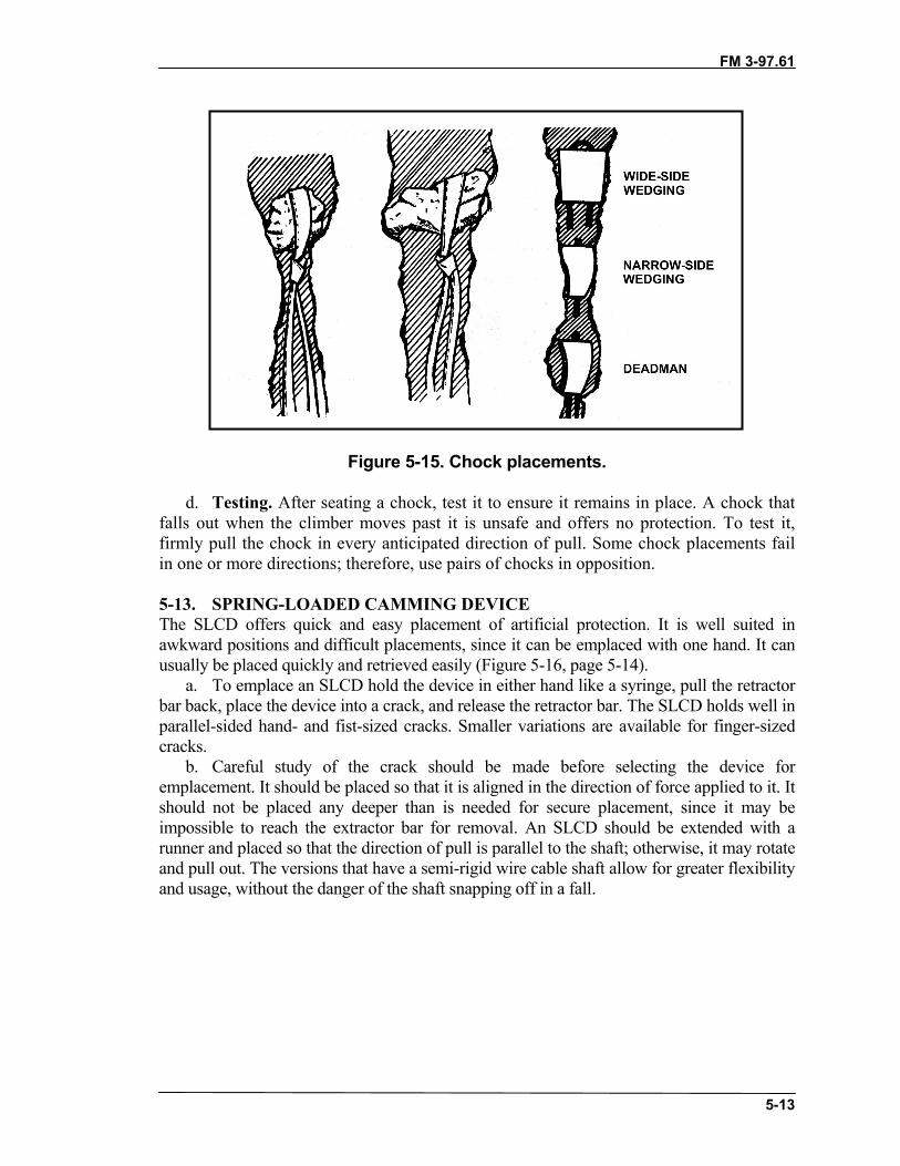
FM 3-97.61
5-13
Figure 5-15. Chock placements.
d. Testing. After seating a chock, test it to ensure it remains in place. A chock thatfalls out when the climber moves past it is unsafe and offers no protection. To test it,firmly pull the chock in every anticipated direction of pull. Some chock placements failin one or more directions; therefore, use pairs of chocks in opposition.
5-13. SPRING-LOADED CAMMING DEVICEThe SLCD offers quick and easy placement of artificial protection. It is well suited inawkward positions and difficult placements, since it can be emplaced with one hand. It canusually be placed quickly and retrieved easily (Figure 5-16, page 5-14).
a. To emplace an SLCD hold the device in either hand like a syringe, pull the retractorbar back, place the device into a crack, and release the retractor bar. The SLCD holds well inparallel-sided hand- and fist-sized cracks. Smaller variations are available for finger-sizedcracks.
b. Careful study of the crack should be made before selecting the device foremplacement. It should be placed so that it is aligned in the direction of force applied to it. Itshould not be placed any deeper than is needed for secure placement, since it may beimpossible to reach the extractor bar for removal. An SLCD should be extended with arunner and placed so that the direction of pull is parallel to the shaft; otherwise, it may rotateand pull out. The versions that have a semi-rigid wire cable shaft allow for greater flexibilityand usage, without the danger of the shaft snapping off in a fall.

FM 3-97.61
5-14
Figure 5-16. SLCD placements.
5-14. BOLTSBolts are often used in fixed-rope installations and in aid climbing where cracks are notavailable.
a. Bolts provide one of the most secure means of establishing protection. The rockshould be inspected for evidence of crumbling, flaking, or cracking, and should be testedwith a hammer. Emplacing a bolt with a hammer and a hand drill is a time-consuming anddifficult process that requires drilling a hole in the rock deeper than the length of the bolt.This normally takes more than 20 minutes for one hole. Electric or even gas-powered drillscan be used to greatly shorten drilling time. However, their size and weight can make themdifficult to carry on the climbing route.
b. A hanger (carrier) and nut are placed on the bolt, and the bolt is inserted and thendriven into the hole. A climber should never hammer on a bolt to test or “improve” it, sincethis permanently weakens it. Bolts should be used with carriers, carabiners, and runners.
c. When using bolts, the climber uses a piton hammer and hand drill with a masonrybit for drilling holes. Some versions are available in which the sleeve is hammered andturned into the rock (self-drilling), which bores the hole. Split bolts and expanding sleevesare common bolts used to secure hangers and carriers (Figure 5-17). Surgical tubing isuseful in blowing dust out of the holes. Nail type bolts are emplaced by driving the nail witha hammer to expand the sleeve against the wall of the drilled hole. Safety glasses shouldalways be worn when emplacing bolts.

FM 3-97.61
5-15
Figure 5-17. Bolt with expanding sleeve.
5-15. EQUALIZING ANCHORSEqualizing anchors are made up of more than one anchor point joined together so that theintended load is shared equally. This not only provides greater anchor strength, but alsoadds redundancy or backup because of the multiple points.
a. Self-equalizing Anchor. A self-equalizing anchor will maintain an equal load oneach individual point as the direction of pull changes (Figure 5-18). This is sometimesused in rappelling when the route must change left or right in the middle of the rappel. Aself-equalizing anchor should only be used when necessary because if any one of theindividual points fail, the anchor will extend and shock-load the remaining points or evencause complete anchor failure.
Figure 5-18. Self-equalizing anchors.
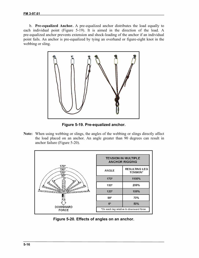
FM 3-97.61
5-16
b. Pre-equalized Anchor. A pre-equalized anchor distributes the load equally toeach individual point (Figure 5-19). It is aimed in the direction of the load. Apre-equalized anchor prevents extension and shock-loading of the anchor if an individualpoint fails. An anchor is pre-equalized by tying an overhand or figure-eight knot in thewebbing or sling.
Figure 5-19. Pre-equalized anchor.
Note: When using webbing or slings, the angles of the webbing or slings directly affectthe load placed on an anchor. An angle greater than 90 degrees can result inanchor failure (Figure 5-20).
Figure 5-20. Effects of angles on an anchor.

FM 3-97.61(TC 90-6-1)
6-1
CHAPTER 6CLIMBING
A steep rock face is a terrain feature that can be avoided most of thetime through prior planning and good route selection. Rock climbing canbe time consuming, especially for a larger unit with a heavy combat load.It can leave the climbing party totally exposed to weather, terrain hazards,and the enemy for the length of the climb.
Sometimes steep rock cannot be avoided. Climbing relatively shortsections of steep rock (one or two pitches) may prove quicker and saferthan using alternate routes. A steep rock route would normally beconsidered an unlikely avenue of approach and, therefore, might beweakly defended or not defended at all.
All personnel in a unit preparing for deployment to mountainousterrain should be trained in the basics of climbing. Forward observers,reconnaissance personnel, and security teams are a few examples of smallunits who may require rock climbing skills to gain their vantage points inmountainous terrain. Select personnel demonstrating the highest degree ofskill and experience should be trained in roped climbing techniques. Thesepersonnel will have the job of picking and “fixing” the route for the rest ofthe unit.
Rock climbing has evolved into a specialized “sport” with a widerange of varying techniques and styles. This chapter focuses on the basicsmost applicable to military operations.
Section I. CLIMBING FUNDAMENTALSA variety of refined techniques are used to climb different types of rock formations. Thefoundation for all of these styles is the art of climbing. Climbing technique stressesclimbing with the weight centered over the feet, using the hands primarily for balance. Itcan be thought of as a combination of the balanced movement required to walk atightrope and the technique used to ascend a ladder. No mountaineering equipment isrequired; however, the climbing technique is also used in roped climbing.
6-1. ROUTE SELECTIONThe experienced climber has learned to climb with the “eyes.” Even before getting on therock, the climber studies all possible routes, or “lines,” to the top looking for cracks,ledges, nubbins, and other irregularities in the rock that will be used for footholds andhandholds, taking note of any larger ledges or benches for resting places. When pickingthe line, he mentally climbs the route, rehearsing the step-by-step sequence of movementsthat will be required to do the climb, ensuring himself that the route has an adequatenumber of holds and the difficulty of the climb will be well within the limit of his ability.
6-2. TERRAIN SELECTION FOR TRAININGRoute selection for military climbing involves picking the easiest and quickest possibleline for all personnel to follow. However, climbing skill and experience can only be
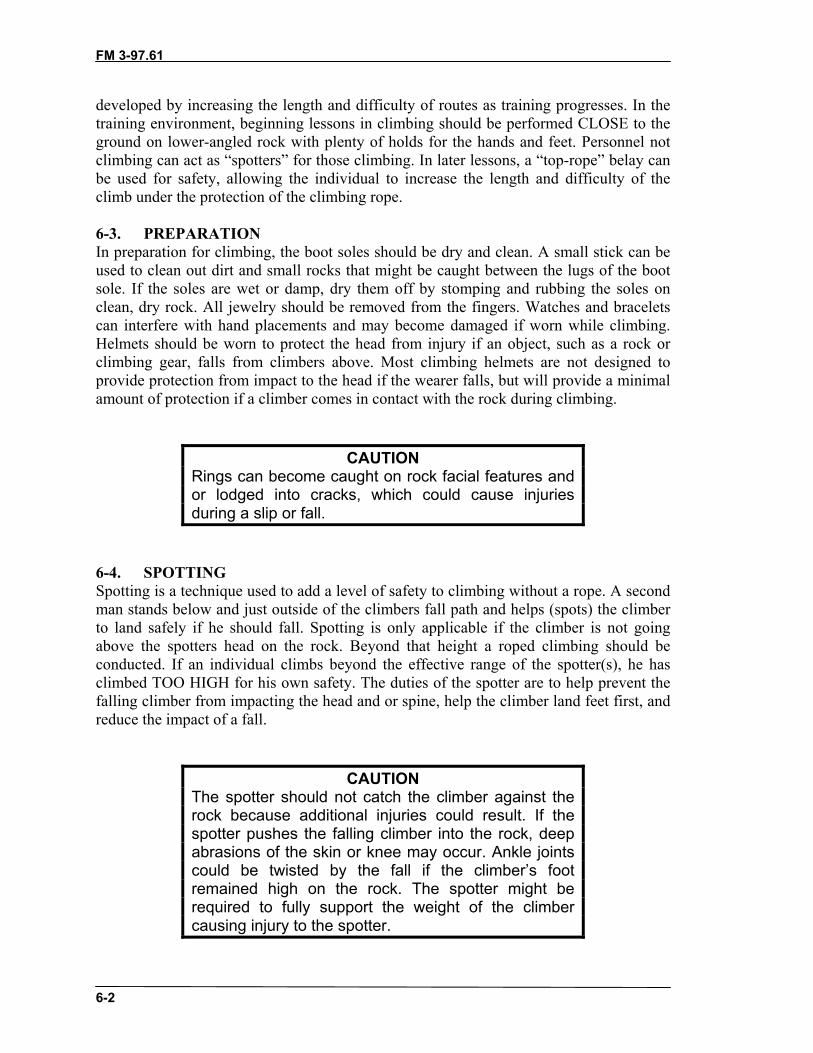
FM 3-97.61
6-2
developed by increasing the length and difficulty of routes as training progresses. In thetraining environment, beginning lessons in climbing should be performed CLOSE to theground on lower-angled rock with plenty of holds for the hands and feet. Personnel notclimbing can act as “spotters” for those climbing. In later lessons, a “top-rope” belay canbe used for safety, allowing the individual to increase the length and difficulty of theclimb under the protection of the climbing rope.
6-3. PREPARATIONIn preparation for climbing, the boot soles should be dry and clean. A small stick can beused to clean out dirt and small rocks that might be caught between the lugs of the bootsole. If the soles are wet or damp, dry them off by stomping and rubbing the soles onclean, dry rock. All jewelry should be removed from the fingers. Watches and braceletscan interfere with hand placements and may become damaged if worn while climbing.Helmets should be worn to protect the head from injury if an object, such as a rock orclimbing gear, falls from climbers above. Most climbing helmets are not designed toprovide protection from impact to the head if the wearer falls, but will provide a minimalamount of protection if a climber comes in contact with the rock during climbing.
CAUTIONRings can become caught on rock facial features andor lodged into cracks, which could cause injuriesduring a slip or fall.
6-4. SPOTTINGSpotting is a technique used to add a level of safety to climbing without a rope. A secondman stands below and just outside of the climbers fall path and helps (spots) the climberto land safely if he should fall. Spotting is only applicable if the climber is not goingabove the spotters head on the rock. Beyond that height a roped climbing should beconducted. If an individual climbs beyond the effective range of the spotter(s), he hasclimbed TOO HIGH for his own safety. The duties of the spotter are to help prevent thefalling climber from impacting the head and or spine, help the climber land feet first, andreduce the impact of a fall.
CAUTIONThe spotter should not catch the climber against therock because additional injuries could result. If thespotter pushes the falling climber into the rock, deepabrasions of the skin or knee may occur. Ankle jointscould be twisted by the fall if the climber’s footremained high on the rock. The spotter might berequired to fully support the weight of the climbercausing injury to the spotter.
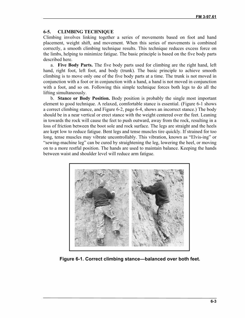
FM 3-97.61
6-3
6-5. CLIMBING TECHNIQUEClimbing involves linking together a series of movements based on foot and handplacement, weight shift, and movement. When this series of movements is combinedcorrectly, a smooth climbing technique results. This technique reduces excess force onthe limbs, helping to minimize fatigue. The basic principle is based on the five body partsdescribed here.
a. Five Body Parts. The five body parts used for climbing are the right hand, lefthand, right foot, left foot, and body (trunk). The basic principle to achieve smoothclimbing is to move only one of the five body parts at a time. The trunk is not moved inconjunction with a foot or in conjunction with a hand, a hand is not moved in conjunctionwith a foot, and so on. Following this simple technique forces both legs to do all thelifting simultaneously.
b. Stance or Body Position. Body position is probably the single most importantelement to good technique. A relaxed, comfortable stance is essential. (Figure 6-1 showsa correct climbing stance, and Figure 6-2, page 6-4, shows an incorrect stance.) The bodyshould be in a near vertical or erect stance with the weight centered over the feet. Leaningin towards the rock will cause the feet to push outward, away from the rock, resulting in aloss of friction between the boot sole and rock surface. The legs are straight and the heelsare kept low to reduce fatigue. Bent legs and tense muscles tire quickly. If strained for toolong, tense muscles may vibrate uncontrollably. This vibration, known as “Elvis-ing” or“sewing-machine leg” can be cured by straightening the leg, lowering the heel, or movingon to a more restful position. The hands are used to maintain balance. Keeping the handsbetween waist and shoulder level will reduce arm fatigue.
Figure 6-1. Correct climbing stance—balanced over both feet.
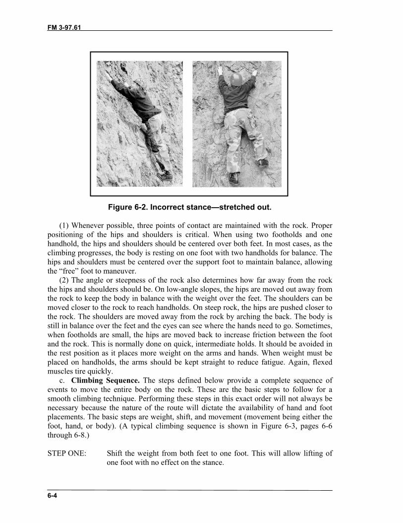
FM 3-97.61
6-4
Figure 6-2. Incorrect stance—stretched out.
(1) Whenever possible, three points of contact are maintained with the rock. Properpositioning of the hips and shoulders is critical. When using two footholds and onehandhold, the hips and shoulders should be centered over both feet. In most cases, as theclimbing progresses, the body is resting on one foot with two handholds for balance. Thehips and shoulders must be centered over the support foot to maintain balance, allowingthe “free” foot to maneuver.
(2) The angle or steepness of the rock also determines how far away from the rockthe hips and shoulders should be. On low-angle slopes, the hips are moved out away fromthe rock to keep the body in balance with the weight over the feet. The shoulders can bemoved closer to the rock to reach handholds. On steep rock, the hips are pushed closer tothe rock. The shoulders are moved away from the rock by arching the back. The body isstill in balance over the feet and the eyes can see where the hands need to go. Sometimes,when footholds are small, the hips are moved back to increase friction between the footand the rock. This is normally done on quick, intermediate holds. It should be avoided inthe rest position as it places more weight on the arms and hands. When weight must beplaced on handholds, the arms should be kept straight to reduce fatigue. Again, flexedmuscles tire quickly.
c. Climbing Sequence. The steps defined below provide a complete sequence ofevents to move the entire body on the rock. These are the basic steps to follow for asmooth climbing technique. Performing these steps in this exact order will not always benecessary because the nature of the route will dictate the availability of hand and footplacements. The basic steps are weight, shift, and movement (movement being either thefoot, hand, or body). (A typical climbing sequence is shown in Figure 6-3, pages 6-6through 6-8.)
STEP ONE: Shift the weight from both feet to one foot. This will allow lifting ofone foot with no effect on the stance.

FM 3-97.61
6-5
STEP TWO: Lift the unweighted foot and place it in a new location, within one totwo feet of the starting position, with no effect on body position orbalance (higher placement will result in a potentially higher lift for thelegs to make, creating more stress, and is called a high step) The trunkdoes not move during foot movement.
STEP THREE: Shift the weight onto both feet. (Repeat steps 1 through 3 forremaining foot.)
STEP FOUR: Lift the body into a new stance with both legs.STEP FIVE: Move one hand to a new position between waist and head height.
During this movement, the trunk should be completely balanced inposition and the removed hand should have no effect on stability.
STEP SIX: Move the remaining hand as in Step 5.
Now the entire body is in a new position and ready to start the process again. Followingthese steps will prevent lifting with the hands and arms, which are used to maintainstance and balance. If both legs are bent, leg extension can be performed as soon as onefoot has been moved. Hand movements can be delayed until numerous foot movementshave been made, which not only creates shorter lifts with the legs, but may allow a betterchoice for the next hand movements because the reach will have increased.

FM 3-97.61
6-6
Figure 6-3. Typical climbing sequence.

FM 3-97.61
6-7
Figure 6-3. Typical climbing sequence (continued).
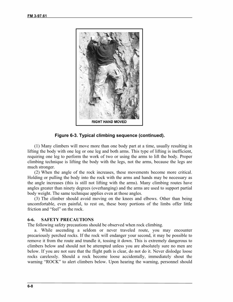
FM 3-97.61
6-8
Figure 6-3. Typical climbing sequence (continued).
(1) Many climbers will move more than one body part at a time, usually resulting inlifting the body with one leg or one leg and both arms. This type of lifting is inefficient,requiring one leg to perform the work of two or using the arms to lift the body. Properclimbing technique is lifting the body with the legs, not the arms, because the legs aremuch stronger.
(2) When the angle of the rock increases, these movements become more critical.Holding or pulling the body into the rock with the arms and hands may be necessary asthe angle increases (this is still not lifting with the arms). Many climbing routes haveangles greater than ninety degrees (overhanging) and the arms are used to support partialbody weight. The same technique applies even at those angles.
(3) The climber should avoid moving on the knees and elbows. Other than beinguncomfortable, even painful, to rest on, these bony portions of the limbs offer littlefriction and “feel” on the rock.
6-6. SAFETY PRECAUTIONSThe following safety precautions should be observed when rock climbing.
a. While ascending a seldom or never traveled route, you may encounterprecariously perched rocks. If the rock will endanger your second, it may be possible toremove it from the route and trundle it, tossing it down. This is extremely dangerous toclimbers below and should not be attempted unless you are absolutely sure no men arebelow. If you are not sure that the flight path is clear, do not do it. Never dislodge looserocks carelessly. Should a rock become loose accidentally, immediately shout thewarning “ROCK” to alert climbers below. Upon hearing the warning, personnel should

FM 3-97.61
6-9
seek immediate cover behind any rock bulges or overhangs available, or flattenthemselves against the rock to minimize exposure.
b. Should a climber fall, he should do his utmost to maintain control and not panic.If on a low-angle climb, he may be able to arrest his own fall by staying in contact withthe rock, grasping for any possible hold available. He should shout the warning“FALLING” to alert personnel below.
CAUTIONGrasping at the rock in a fall can result in seriousinjuries to the upper body. If conducting a ropedclimb, let the rope provide protection.
c. When climbing close to the ground and without a rope, a spotter can be used forsafety. The duties of the spotter are to ensure the falling climber does not impact the heador spine, and to reduce the impact of a fall.
d. Avoid climbing directly above or below other climbers (with the exception ofspotters). When personnel must climb at the same time, following the same line, a fixedrope should be installed.
e. Avoid climbing with gloves on because of the decreased “feel” for the rock. Theuse of gloves in the training environment is especially discouraged, while their use in themountains is often mandatory when it is cold. A thin polypropylene or wool glove is bestfor rock climbing, although heavier cotton or leather work gloves are often used forbelaying.
f. Be extremely careful when climbing on wet or moss-covered rock; friction onholds is greatly reduced.
g. Avoid grasping small vegetation for handholds; the root systems can be shallowand will usually not support much weight.
6-7. MARGIN OF SAFETYBesides observing the standard safety precautions, the climber can avoid catastrophe byclimbing with a wide margin of safety. The margin of safety is a protective buffer theclimber places between himself and potential climbing hazards. Both subjective(personnel-related) and objective (environmental) hazards must be considered whenapplying the margin of safety. The leader must apply the margin of safety taking intoaccount the strengths and weaknesses of the entire team or unit.
a. When climbing, the climber increases his margin of safety by selecting routes thatare well within the limit of his ability. When leading a group of climbers, he selects aroute well within the ability of the weakest member.
b. When the rock is wet, or when climbing in other adverse weather conditions, theclimber’s ability is reduced and routes are selected accordingly. When the climbingbecomes difficult or exposed, the climber knows to use the protection of the climbingrope and belays. A lead climber increases his margin of safety by placing protectionalong the route to limit the length of a potential fall.

FM 3-97.61
6-10
Section II. USE OF HOLDSThe climber should check each hold before use. This may simply be a quick, visualinspection if he knows the rock to be solid. When in doubt, he should grab and tug on thehold to test it for soundness BEFORE depending on it. Sometimes, a hold that appearsweak can actually be solid as long as minimal force is applied to it, or the force is appliedin a direction that strengthens it. A loose nubbin might not be strong enough to supportthe climber’s weight, but it may serve as an adequate handhold. Be especially carefulwhen climbing on weathered, sedimentary-type rock.
6-8. CLIMBING WITH THE FEET“Climb with the feet and use the hands for balance” is extremely important to remember.In the early learning stages of climbing, most individuals will rely heavily on the arms,forgetting to use the feet properly. It is true that solid handholds and a firm grip areneeded in some combination techniques; however, even the most strenuous techniquesrequire good footwork and a quick return to a balanced position over one or both feet.Failure to climb any route, easy or difficult, is usually the result of poor footwork.
a. The beginning climber will have a natural tendency to look up for handholds. Tryto keep the hands low and train your eyes to look down for footholds. Even the smallestirregularity in the rock can support the climber once the foot is positioned properly andweight is committed to it.
b. The foot remains on the rock as a result of friction. Maximum friction is obtainedfrom a correct stance over a properly positioned foot. The following describes a few waysthe foot can be positioned on the rock to maximize friction.
(1) Maximum Sole Contact. The principle of using full sole contact, as in mountainwalking, also applies in climbing. Maximum friction is obtained by placing as much ofthe boot sole on the rock as possible. Also, the leg muscles can relax the most when theentire foot is placed on the rock. (Figure 6-4 shows examples of maximum and minimumsole contact.)
(a) Smooth, low-angled rock (slab) and rock containing large “bucket” holds andledges are typical formations where the entire boot sole should be used.
(b) On some large holds, like bucket holds that extend deep into the rock, the entirefoot cannot be used. The climber may not be able to achieve a balanced position if thefoot is stuck too far underneath a bulge in the rock. In this case, placing only part of thefoot on the hold may allow the climber to achieve a balanced stance. The key is to use asmuch of the boot sole as possible. Remember to keep the heels low to reduce strain on thelower leg muscles.
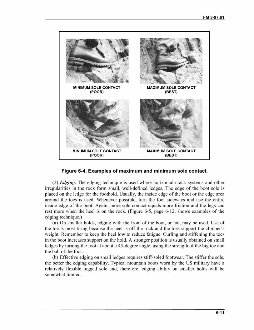
FM 3-97.61
6-11
Figure 6-4. Examples of maximum and minimum sole contact.
(2) Edging. The edging technique is used where horizontal crack systems and otherirregularities in the rock form small, well-defined ledges. The edge of the boot sole isplaced on the ledge for the foothold. Usually, the inside edge of the boot or the edge areaaround the toes is used. Whenever possible, turn the foot sideways and use the entireinside edge of the boot. Again, more sole contact equals more friction and the legs canrest more when the heel is on the rock. (Figure 6-5, page 6-12, shows examples of theedging technique.)
(a) On smaller holds, edging with the front of the boot, or toe, may be used. Use ofthe toe is most tiring because the heel is off the rock and the toes support the climber’sweight. Remember to keep the heel low to reduce fatigue. Curling and stiffening the toesin the boot increases support on the hold. A stronger position is usually obtained on smallledges by turning the foot at about a 45-degree angle, using the strength of the big toe andthe ball of the foot.
(b) Effective edging on small ledges requires stiff-soled footwear. The stiffer the sole,the better the edging capability. Typical mountain boots worn by the US military have arelatively flexible lugged sole and, therefore, edging ability on smaller holds will besomewhat limited.

FM 3-97.61
6-12
Figure 6-5. Examples of edging technique.
(3) Smearing. When footholds are too small to use a good edging technique, the ballof the foot can be “smeared” over the hold. The smearing technique requires the boot toadhere to the rock by deformation of the sole and by friction. Rock climbing shoes arespecifically designed to maximize friction for smearing; some athletic shoes also workwell. The Army mountain boot, with its softer sole, usually works better for smearingthan for edging. Rounded, down-sloping ledges and low-angled slab rock often requiregood smearing technique. (Figure 6-6 shows examples of the smearing technique.)
(a) Effective smearing requires maximum friction between the foot and the rock.Cover as much of the hold as possible with the ball of the foot. Keeping the heel low willnot only reduce muscle strain, but will increase the amount of surface contact betweenthe foot and the rock.
(b) Sometimes flexing the ankles and knees slightly will place the climber’s weightmore directly over the ball of the foot and increase friction; however, this is more tiringand should only be used for quick, intermediate holds. The leg should be kept straightwhenever possible.
Figure 6-6. Examples of the smearing technique.
(4) Jamming. The jamming technique works on the same principal as chockplacement. The foot is set into a crack in such a way that it “jams” into place, resisting adownward pull. The jamming technique is a specialized skill used to climb vertical or
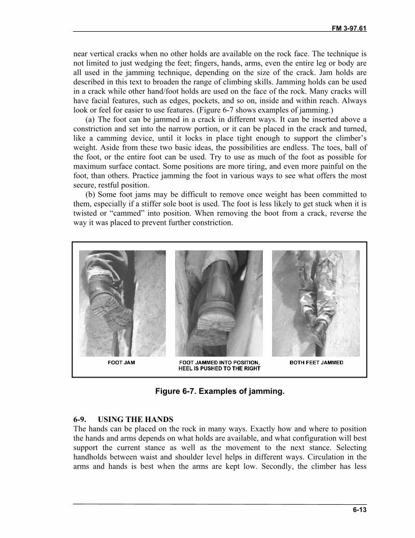
FM 3-97.61
6-13
near vertical cracks when no other holds are available on the rock face. The technique isnot limited to just wedging the feet; fingers, hands, arms, even the entire leg or body areall used in the jamming technique, depending on the size of the crack. Jam holds aredescribed in this text to broaden the range of climbing skills. Jamming holds can be usedin a crack while other hand/foot holds are used on the face of the rock. Many cracks willhave facial features, such as edges, pockets, and so on, inside and within reach. Alwayslook or feel for easier to use features. (Figure 6-7 shows examples of jamming.)
(a) The foot can be jammed in a crack in different ways. It can be inserted above aconstriction and set into the narrow portion, or it can be placed in the crack and turned,like a camming device, until it locks in place tight enough to support the climber’sweight. Aside from these two basic ideas, the possibilities are endless. The toes, ball ofthe foot, or the entire foot can be used. Try to use as much of the foot as possible formaximum surface contact. Some positions are more tiring, and even more painful on thefoot, than others. Practice jamming the foot in various ways to see what offers the mostsecure, restful position.
(b) Some foot jams may be difficult to remove once weight has been committed tothem, especially if a stiffer sole boot is used. The foot is less likely to get stuck when it istwisted or “cammed” into position. When removing the boot from a crack, reverse theway it was placed to prevent further constriction.
Figure 6-7. Examples of jamming.
6-9. USING THE HANDSThe hands can be placed on the rock in many ways. Exactly how and where to positionthe hands and arms depends on what holds are available, and what configuration will bestsupport the current stance as well as the movement to the next stance. Selectinghandholds between waist and shoulder level helps in different ways. Circulation in thearms and hands is best when the arms are kept low. Secondly, the climber has less

FM 3-97.61
6-14
tendency to “hang” on his arms when the handholds are at shoulder level and below. Bothof these contribute to a relaxed stance and reduce fatigue in the hands and arms.
a. As the individual climbs, he continually repositions his hands and arms to keepthe body in balance, with the weight centered over the feet. On lower-angled rock, hemay simply need to place the hands up against the rock and extend the arm to maintainbalance; just like using an ice ax as a third point of contact in mountain walking.Sometimes, he will be able to push directly down on a large hold with the palm of thehand. More often though, he will need to “grip” the rock in some fashion and then pushor pull against the hold to maintain balance.
b. As stated earlier, the beginner will undoubtedly place too much weight on thehands and arms. If we think of ourselves climbing a ladder, our body weight is on ourlegs. Our hands grip, and our arms pull on each rung only enough to maintain our balanceand footing on the ladder. Ideally, this is the amount of grip and pull that should be usedin climbing. Of course, as the size and availability of holds decreases, and the steepnessof the rock approaches the vertical, the grip must be stronger and more weight might beplaced on the arms and handholds for brief moments. The key is to move quickly fromthe smaller, intermediate holds to the larger holds where the weight can be placed backon the feet allowing the hands and arms to relax. The following describes some of thebasic handholds and how the hand can be positioned to maximize grip on smaller holds.
(1) Push Holds. Push holds rely on the friction created when the hand is pushedagainst the rock. Most often a climber will use a push hold by applying “downwardpressure” on a ledge or nubbin. This is fine, and works well; however, the climber shouldnot limit his use of push holds to the application of down pressure. Pushing sideways, andon occasion, even upward on less obvious holds can prove quite secure. Push holds oftenwork best when used in combination with other holds. Pushing in opposite directions and“push-pull” combinations are excellent techniques. (Figure 6-8 shows examples of pushholds.)
(a) An effective push hold does not necessarily require the use of the entire hand. Onsmaller holds, the side of the palm, the fingers, or the thumb may be all that is needed tosupport the stance. Some holds may not feel secure when the hand is initially placed onthem. The hold may improve or weaken during the movement. The key is to try andselect a hold that will improve as the climber moves past it.
(b) Most push holds do not require much grip; however, friction might be increasedby taking advantage of any rough surfaces or irregularities in the rock. Sometimes thestrength of the hold can be increased by squeezing, or “pinching,” the rock between thethumb and fingers (see paragraph on pinch holds).

FM 3-97.61
6-15
Figure 6-8. Examples of push holds.
(2) Pull Holds. Pull holds, also called “cling holds,” which are grasped and pulledupon, are probably the most widely used holds in climbing. Grip plays more of a role in apull hold, and, therefore, it normally feels more secure to the climber than a push hold.Because of this increased feeling of security, pull holds are often overworked. These arethe holds the climber has a tendency to hang from. Most pull holds do not require greatstrength, just good technique. Avoid the “death grip” syndrome by climbing with the feet.(Figure 6-9, page 6-16, shows examples of pull holds.)
(a) Like push holds, pressure on a pull hold can be applied straight down, sideways,or upward. Again, these are the holds the climber tends to stretch and reach for, creatingan unbalanced stance. Remember to try and keep the hands between waist and shoulderlevel, making use of intermediate holds instead of reaching for those above the head.
(b) Pulling sideways on vertical cracks can be very secure. There is less tendency tohang from “side-clings” and the hands naturally remain lower. The thumb can often pushagainst one side of the crack, in opposition to the pull by the fingers, creating a strongerhold. Both hands can also be placed in the same crack, with the hands pulling in oppositedirections. The number of possible combinations is limited only by the imagination andexperience of the climber.
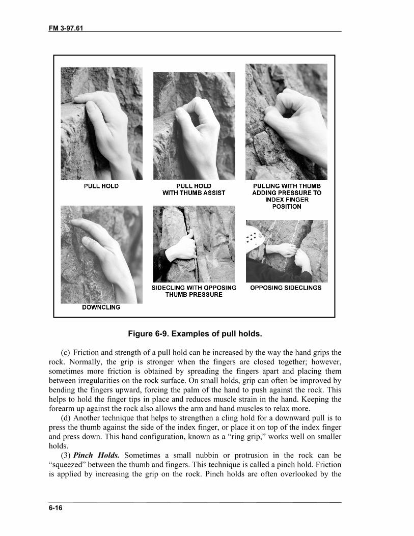
FM 3-97.61
6-16
Figure 6-9. Examples of pull holds.
(c) Friction and strength of a pull hold can be increased by the way the hand grips therock. Normally, the grip is stronger when the fingers are closed together; however,sometimes more friction is obtained by spreading the fingers apart and placing thembetween irregularities on the rock surface. On small holds, grip can often be improved bybending the fingers upward, forcing the palm of the hand to push against the rock. Thishelps to hold the finger tips in place and reduces muscle strain in the hand. Keeping theforearm up against the rock also allows the arm and hand muscles to relax more.
(d) Another technique that helps to strengthen a cling hold for a downward pull is topress the thumb against the side of the index finger, or place it on top of the index fingerand press down. This hand configuration, known as a “ring grip,” works well on smallerholds.
(3) Pinch Holds. Sometimes a small nubbin or protrusion in the rock can be“squeezed” between the thumb and fingers. This technique is called a pinch hold. Frictionis applied by increasing the grip on the rock. Pinch holds are often overlooked by the

FM 3-97.61
6-17
novice climber because they feel insecure at first and cannot be relied upon to supportmuch body weight. If the climber has his weight over his feet properly, the pinch holdwill work well in providing balance. The pinch hold can also be used as a grippingtechnique for push holds and pull holds. (Figure 6-10 shows examples of pinch holds.)
Figure 6-10. Examples of pinch holds.
(4) Jam Holds. Like foot jams, the fingers and hands can be wedged or cammed intoa crack so they resist a downward or outward pull. Jamming with the fingers and handscan be painful and may cause minor cuts and abrasions to tender skin. Cotton tape can beused to protect the fingertips, knuckles, and the back of the hand; however, prolongedjamming technique requiring hand taping should be avoided. Tape also adds friction tothe hand in jammed position. (Figure 6-11, page 6-18, shows examples of jam holds.)
(a) The hand can be placed in a crack a number of ways. Sometimes an open handcan be inserted and wedged into a narrower portion of the crack. Other times a clenchedfist will provide the necessary grip. Friction can be created by applying cross pressurebetween the fingers and the back of the hand. Another technique for vertical cracks is toplace the hand in the crack with the thumb pointed either up or down. The hand is thenclenched as much as possible. When the arm is straightened, it will twist the hand andtend to cam it into place. This combination of clenching and camming usually producesthe most friction, and the most secure hand jam in vertical cracks.
(b) In smaller cracks, only the fingers will fit. Use as many fingers as the crack willallow. The fingers can sometimes be stacked in some configuration to increase friction.The thumb is usually kept outside the crack in finger jams and pressed against the rock toincrease friction or create cross pressure. In vertical cracks it is best to insert the fingerswith the thumb pointing down to make use of the natural camming action of the fingersthat occurs when the arm is twisted towards a normal position.
(c) Jamming technique for large cracks, or “off widths,” requiring the use of arm, leg,and body jams, is another technique. To jam or cam an arm, leg, or body into an offwidth, the principle is the same as for fingers, hands, or feet—you are making thejammed appendage “fatter” by folding or twisting it inside the crack. For off widths, youmay place your entire arm inside the crack with the arm folded and the palm pointingoutward. The leg can be used, from the calf to the thigh, and flexed to fit the crack.Routes requiring this type of climbing should be avoided as the equipment normally used
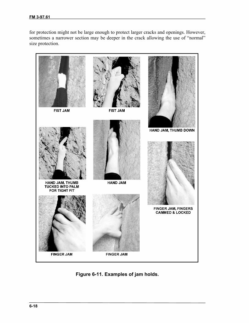
FM 3-97.61
6-18
for protection might not be large enough to protect larger cracks and openings. However,sometimes a narrower section may be deeper in the crack allowing the use of “normal”size protection.
Figure 6-11. Examples of jam holds.

FM 3-97.61
6-19
6-10. COMBINATION TECHNIQUESThe positions and holds previously discussed are the basics and the ones most common toclimbing. From these fundamentals, numerous combination techniques are possible. Asthe climber gains experience, he will learn more ways to position the hands, feet, andbody in relation to the holds available; however, he should always strive to climb with hisweight on his feet from a balanced stance.
a. Sometimes, even on an easy route, the climber may come upon a section of therock that defies the basic principles of climbing. Short of turning back, the onlyalternative is to figure out some combination technique that will work. Many of thesetype problems require the hands and feet to work in opposition to one another. Most willplace more weight on the hands and arms than is desirable, and some will put the climberin an “out of balance” position. To make the move, the climber may have to “break therules” momentarily. This is not a problem and is done quite frequently by experiencedclimbers. The key to using these type of combination techniques is to plan and executethem deliberately, without lunging or groping for holds, yet quickly, before the hands,arms, or other body parts tire. Still, most of these maneuvers require good technique morethan great strength, though a certain degree of hand and arm strength certainly helps.
b. Combination possibilities are endless. The following is a brief description of someof the more common techniques.
(1) Change Step. The change step, or hop step, can be used when the climber needsto change position of the feet. It is commonly used when traversing to avoid crossing thefeet, which might put the climber in an awkward position. To prevent an off balancesituation, two solid handholds should be used. The climber simply places his weight onhis handholds while he repositions the feet. He often does this with a quick “hop,”replacing the lead foot with the trail foot on the same hold. Keeping the forearms againstthe rock during the maneuver takes some of the strain off the hands, while at the sametime strengthening the grip on the holds.
(2) Mantling. Mantling is a technique that can be used when the distance between theholds increases and there are no immediate places to move the hands or feet. It doesrequire a ledge (mantle) or projection in the rock that the climber can press straight downupon. (Figure 6-12, page 6-20, shows the mantling sequence.)
(a) When the ledge is above head height, mantling begins with pull holds, usually“hooking” both hands over the ledge. The climber pulls himself up until his head is abovethe hands, where the pull holds become push holds. He elevates himself until the arms arestraight and he can lock the elbows to relax the muscles. Rotating the hands inwardduring the transition to push holds helps to place the palms more securely on the ledge.Once the arms are locked, a foot can be raised and placed on the ledge. The climber mayhave to remove one hand to make room for the foot. Mantling can be fairly strenuous;however, most individuals should be able to support their weight, momentarily, on onearm if they keep it straight and locked. With the foot on the ledge, weight can be takenoff the arms and the climber can grasp the holds that were previously out of reach. Oncebalanced over the foot, he can stand up on the ledge and plan his next move.
(b) Pure mantling uses arm strength to raise the body; however, the climber can oftensmear the balls of the feet against the rock and “walk” the feet up during the maneuver totake some of the weight off the arms. Sometimes edges will be available for short steps inthe process.

FM 3-97.61
6-20
Figure 6-12. Mantling sequence.
(3) Undercling. An “undercling” is a classic example of handholds and footholdsworking in opposition (Figure 6-13). It is commonly used in places where the rock

FM 3-97.61
6-21
projects outward, forming a bulge or small overhang. Underclings can be used in the topsof buckets, also. The hands are placed “palms-up” underneath the bulge, applying anupward pull. Increasing this upward pull creates a counterforce, or body tension, whichapplies more weight and friction to the footholds. The arms and legs should be kept asstraight as possible to reduce fatigue. The climber can often lean back slightly in theundercling position, enabling him to see above the overhang better and search for thenext hold.
Figure 6-13. Undercling.
(4) Lieback. The “lieback” is another good example of the hands working inopposition to the feet. The technique is often used in a vertical or diagonal crackseparating two rock faces that come together at, more or less, a right angle (commonlyreferred to as a dihedral). The crack edge closest to the body is used for handholds whilethe feet are pressed against the other edge. The climber bends at the waist, putting thebody into an L-shaped position. Leaning away from the crack on two pull holds, bodytension creates friction between the feet and the hands. The feet must be kept relativelyhigh to maintain weight, creating maximum friction between the sole and the rocksurface. Either full sole contact or the smearing technique can be used, whichever seemsto produce the most friction.
(a) The climber ascends a dihedral by alternately shuffling the hands and feetupward. The lieback technique can be extremely tiring, especially when the dihedral isnear vertical. If the hands and arms tire out before completing the sequence, the climberwill likely fall. The arms should be kept straight throughout the entire maneuver so theclimber’s weight is pulling against bones and ligaments, rather than muscle. The legsshould be straightened whenever possible.
(b) Placing protection in a lieback is especially tiring. Look for edges or pockets forthe feet in the crack or on the face for a better position to place protection from, or for arest position. Often, a lieback can be avoided with closer examination of the available

FM 3-97.61
6-22
face features. The lieback can be used alternately with the jamming technique, or viceversa, for variation or to get past a section of a crack with difficult or nonexistent jampossibilities. The lieback can sometimes be used as a face maneuver (Figure 6-14).
Figure 6-14. Lieback on a face.
(5) Stemming. When the feet work in opposition from a relatively wide stance, themaneuver is known as stemming. The stemming technique can sometimes be used onfaces, as well as in a dihedral in the absence of solid handholds for the lieback(Figure 6-15).
Figure 6-15. Stemming on a face.

FM 3-97.61
6-23
(a) The classic example of stemming is when used in combination with two opposingpush holds in wide, parallel cracks, known as chimneys. Chimneys are cracks in whichthe walls are at least 1 foot apart and just big enough to squeeze the body into. Friction iscreated by pushing outward with the hands and feet on each side of the crack. Theclimber ascends the chimney by alternately moving the hands and feet up the crack(Figure 6-16). Applying pressure with the back and bottom is usually necessary in widerchimneys. Usually, full sole contact of the shoes will provide the most friction, althoughsmearing may work best in some instances. Chimneys that do not allow a full stemmingposition can be negotiated using the arms, legs, or body as an integral contact point. Thistechnique will often feel more secure since there is more body to rock contact.
Figure 6-16. Chimney sequence.

FM 3-97.61
6-24
Figure 6-16. Chimney sequence (continued).
(b) The climber can sometimes rest by placing both feet on the same side of thecrack, forcing the body against the opposing wall. The feet must be kept relatively highup under the body so the force is directed sideways against the walls of the crack. Thearms should be straightened with the elbows locked whenever possible to reduce musclestrain. The climber must ensure that the crack does not widen beyond the climbable widthbefore committing to the maneuver. Remember to look for face features inside chimneysfor more security in the climb.
(c) Routes requiring this type of climbing should be avoided as the equipmentnormally used for protection might not be large enough to protect chimneys. However,face features, or a much narrower crack in one or both corners, may sometimes be founddeeper in the chimney allowing the use of normal size protection.
(6) Slab Technique. A slab is a relatively smooth, low-angled rock formation thatrequires a slightly modified climbing technique (Figure 6-17). Since slab rock normallycontains few, if any holds, the technique requires maximum friction and perfect balanceover the feet.
(a) On lower-angled slab, the climber can often stand erect and climb using full solecontact and other mountain walking techniques. On steeper slab, the climber will need toapply good smearing technique. Often, maximum friction cannot be attained on steeperslab from an erect stance. The climber will have to flex the ankles and knees so hisweight is placed more directly over the balls of the feet. He may then have to bend at thewaist to place the hands on the rock, while keeping the hips over his feet.
(b) The climber must pay attention to any changes in slope angle and adjust his bodyaccordingly. Even the slightest change in the position of the hips over the feet can mean

FM 3-97.61
6-25
the difference between a good grip or a quick slip. The climber should also takeadvantage of any rough surfaces, or other irregularities in the rock he can place his handsor feet on, to increase friction.
Figure 6-17. Slab technique.
(7) Down Climbing. Descending steep rock is normally performed using a ropedmethod; however, the climber may at some point be required to down climb a route. Evenif climbing ropes and related equipment are on hand, down climbing easier terrain isoften quicker than taking the time to rig a rappel point. Also, a climber might find himselfconfronted with difficulties part way up a route that exceed his climbing ability, or theabilities of others to follow. Whatever the case may be, down climbing is a skill wellworth practicing.
CAUTIONS1. Down climbing can inadvertently lead into an
unforeseen dangerous position on a descent.When in doubt, use a roped descent.
2. Down climbing is accomplished at a difficulty levelwell below the ability of the climber. When indoubt, use a roped descent.
(a) On easier terrain, the climber can face outward, away from the rock, enabling himto see the route better and descend quickly. As the steepness and difficulty increase, hecan often turn sideways, still having a good view of the descent route, but being betterable to use the hands and feet on the holds available. On the steepest terrain, the climberwill have to face the rock and down climb using good climbing techniques.
(b) Down climbing is usually more difficult than ascending a given route. Some holdswill be less visible when down climbing, and slips are more likely to occur. The climbermust often lean well away from the rock to look for holds and plan his movements. More

FM 3-97.61
6-26
weight is placed on the arms and handholds at times to accomplish this, as well as to helplower the climber to the next foothold. Hands should be moved to holds as low as waistlevel to give the climber more range of movement with each step. If the handholds aretoo high, he may have trouble reaching the next foothold. The climber must be carefulnot to overextend himself, forcing a release of his handholds before reaching the nextfoothold.
CAUTIONDo not drop from good handholds to a standingposition. A bad landing could lead to injured ankles ora fall beyond the planned landing area.
(c) Descending slab formations can be especially tricky. The generally lower angle ofslab rock may give the climber a false sense of security, and a tendency to move tooquickly. Down climbing must be slow and deliberate, as in ascending, to maintain perfectbalance and weight distribution over the feet. On lower-angle slab the climber may beable to stand more or less erect, facing outward or sideways, and descend using good flatfoot technique. The climber should avoid the tendency to move faster, which can lead touncontrollable speed.
(d) On steeper slab, the climber will normally face the rock and down climb, usingthe same smearing technique as for ascending. An alternate method for descending slab isto face away from the rock in a “crab” position (Figure 6-18). Weight is still concentratedover the feet, but may be shifted partly onto the hands to increase overall friction. Theclimber is able to maintain full sole contact with the rock and see the entire descent route.Allowing the buttocks to “drag behind” on the rock will decrease the actual weight on thefootholds, reducing friction, and leading to the likelihood of a slip. Facing the rock, anddown-climbing with good smearing technique, is usually best on steeper slab.
Figure 6-18. Descending slab in the crab position.
FM 3-97.61
6-27
Section III. ROPED CLIMBINGWhen the angle, length, and difficulty of the proposed climbing route surpasses theability of the climbers’ safety margin (possibly on class 4 and usually on class 5 terrain),ropes must be used to proceed. Roped climbing is only safe if accomplished correctly.Reading this manual does not constitute skill with ropes—much training and practice isnecessary. Many aspects of roped climbing take time to understand and learn. Ropes arenormally not used in training until the basic principles of climbing are covered.
Note: A rope is completely useless for climbing unless the climber knows how to use itsafely.
6-11. TYING-IN TO THE CLIMBING ROPEOver the years, climbers have developed many different knots and procedures fortying-in to the climbing rope. Some of the older methods of tying directly into the roperequire minimal equipment and are relatively easy to inspect; however, they offer littlesupport to the climber, may induce further injuries, and may even lead to strangulation ina severe fall. A severe fall, where the climber might fall 20 feet or more and be leftdangling on the end of the rope, is highly unlikely in most instances, especially for mostpersonnel involved in military climbing. Tying directly into the rope is perfectly safe formany roped party climbs used in training on lower-angled rock. All climbers shouldknow how to properly tie the rope around the waist in case a climbing harness isunavailable.
6-12. PRESEWN HARNESSESAlthough improvised harnesses are made from readily available materials and take littlespace in the pack or pocket, presewn harnesses provide other aspects that should beconsidered. No assembly is required, which reduces preparation time for ropedmovement. All presewn harnesses provide a range of adjustability. These harnesses havea fixed buckle that, when used correctly, will not fail before the nylon materialsconnected to it. However, specialized equipment, such as a presewn harness, reduce theflexibility of gear. Presewn harness are bulky, also.
a. Seat Harness. Many presewn seat harnesses are available with many differentqualities separating them, including cost.
(1) The most notable difference will be the amount and placement of padding. Themore padding the higher the price and the more comfort. Gear loops sewn into the waistbelt on the sides and in the back are a common feature and are usually strong enough tohold quite a few carabiners and or protection. The gear loops will vary in number fromone model/manufacturer to another.
(2) Although most presewn seat harnesses have a permanently attached belay loopconnecting the waist belt and the leg loops, the climbing rope should be run around thewaist belt and leg loop connector. The presewn belay loop adds another link to the chainof possible failure points and only gives one point of security whereas running the ropethrough the waist belt and leg loop connector provides two points of contact.
(3) If more than two men will be on the rope, connect the middle position(s) to therope with a carabiner routed the same as stated in the previous paragraph.
FM 3-97.61
6-28
(4) Many manufactured seat harnesses will have a presewn loop of webbing on therear. Although this loop is much stronger than the gear loops, it is not for a belay anchor.It is a quick attachment point to haul an additional rope.
b. Chest Harness. The chest harness will provide an additional connecting point forthe rope, usually in the form of a carabiner loop to attach a carabiner and rope to. Thistype of additional connection will provide a comfortable hanging position on the rope,but otherwise provides no additional protection from injury during a fall (if the seatharness is fitted correctly).
(1) A chest harness will help the climber remain upright on the rope during rappellingor ascending a fixed rope, especially while wearing a heavy pack. (If rappelling orascending long or multiple pitches, let the pack hang on a drop cord below the feet andattached to the harness tie-in point.)
(2) The presewn chest harnesses available commercially will invariably offer morecomfort or performance features, such as padding, gear loops, or ease of adjustment, thanan improvised chest harness.
c. Full-Body Harness. Full-body harnesses incorporate a chest and seat harness intoone assembly. This is the safest harness to use as it relocates the tie-in point higher, at thechest, reducing the chance of an inverted position when hanging on the rope. This isespecially helpful when moving on ropes with heavy packs. A full-body harness onlyaffects the body position when hanging on the rope and will not prevent head injury in afall.
CAUTIONThis type of harness does not prevent the climberfrom falling head first. Body position during a fall isaffected only by the forces that generated the fall, andthis type of harness promotes an upright position onlywhen hanging on the rope from the attachment point.
6-13. IMPROVISED HARNESSESWithout the use of a manufactured harness, many methods are still available for attachingoneself to a rope. Harnesses can be improvised using rope or webbing and knots.
a. Swami Belt. The swami belt is a simple, belt-only harness created by wrappingrope or webbing around the waistline and securing the ends. One-inch webbing willprovide more comfort. Although an effective swami belt can be assembled with aminimum of one wrap, at least two wraps are recommended for comfort, usually withapproximately ten feet of material. The ends are secured with an appropriate knot.
b. Bowline-on-a-Coil. Traditionally, the standard method for attaching oneself tothe climbing rope was with a bowline-on-a-coil around the waist. The extra wrapsdistribute the force of a fall over a larger area of the torso than a single bowline would,and help prevent the rope from riding up over the rib cage and under the armpits. Theknot must be tied snugly around the narrow part of the waist, just above the bony portionsof the hips (pelvis). Avoid crossing the wraps by keeping them spread over the waistarea. “Sucking in the gut” a bit when making the wraps will ensure a snug fit.

FM 3-97.61
6-29
(1) The bowline-on-a-coil can be used to tie-in to the end of the rope (Figure 6-19).The end man should have a minimum of four wraps around the waist before completingthe knot.
Figure 6-19. Tying-in with a bowline-on-a-coil.
(2) The bowline-on-a-coil is a safe and effective method for attaching to the ropewhen the terrain is low-angled, WITHOUT THE POSSIBILITY OF A SEVERE FALL.When the terrain becomes steeper, a fall will generate more force on the climber and thiswill be felt through the coils of this type of attachment. A hard fall will cause the coils toride up against the ribs. In a severe fall, any tie-in around the waist only could place a“shock load” on the climber’s lower back. Even in a relatively short fall, if the climberends up suspended in mid-air and unable to regain footing on the rock, the rope aroundthe waist can easily cut off circulation and breathing in a relatively short time.
(3) The climbing harness distributes the force of a fall over the entire pelvic region,like a parachute harness. Every climber should know how to tie some sort of improvisedclimbing harness from sling material. A safe, and comfortable, seat/chest combinationharness can be tied from one-inch tubular nylon.
c. Improvised Seat Harness. A seat harness can be tied from a length of webbingapproximately 25 feet long (Figure 6-20, page 6-30).
(1) Locate the center of the rope. Off to one side, tie two fixed loops approximately 6inches apart (overhand loops). Adjust the size of the loops so they fit snugly around thethigh. The loops are tied into the sling “off center” so the remaining ends are differentlengths. The short end should be approximately 4 feet long (4 to 5 feet for largerindividuals).
(2) Slip the leg loops over the feet and up to the crotch, with the knots to the front.Make one complete wrap around the waist with the short end, wrapping to the outside,and hold it in place on the hip. Keep the webbing flat and free of twists when wrapping.
(3) Make two to three wraps around the waist with the long end in the oppositedirection (wrapping to the outside), binding down on the short end to hold it in place.Grasping both ends, adjust the waist wraps to a snug fit. Connect the ends with the
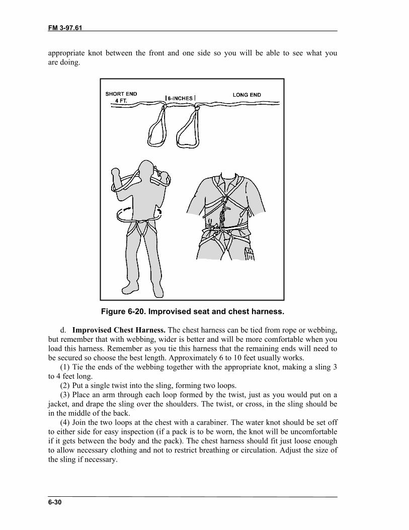
FM 3-97.61
6-30
appropriate knot between the front and one side so you will be able to see what youare doing.
Figure 6-20. Improvised seat and chest harness.
d. Improvised Chest Harness. The chest harness can be tied from rope or webbing,but remember that with webbing, wider is better and will be more comfortable when youload this harness. Remember as you tie this harness that the remaining ends will need tobe secured so choose the best length. Approximately 6 to 10 feet usually works.
(1) Tie the ends of the webbing together with the appropriate knot, making a sling 3to 4 feet long.
(2) Put a single twist into the sling, forming two loops.(3) Place an arm through each loop formed by the twist, just as you would put on a
jacket, and drape the sling over the shoulders. The twist, or cross, in the sling should bein the middle of the back.
(4) Join the two loops at the chest with a carabiner. The water knot should be set offto either side for easy inspection (if a pack is to be worn, the knot will be uncomfortableif it gets between the body and the pack). The chest harness should fit just loose enoughto allow necessary clothing and not to restrict breathing or circulation. Adjust the size ofthe sling if necessary.

FM 3-97.61
6-31
e. Improvised Full-Body Harness. Full-body harnesses incorporate a chest and seatharness into one assembly.
(1) The full-body harness is the safest harness because it relocates the tie-in pointhigher, at the chest, reducing the chance of an inverted hanging position on the rope. Thisis especially helpful when moving on ropes with heavy packs. A full-body harness affectsthe body position only when hanging on the rope.
CAUTIONA full-body harness does not prevent falling head first;body position in a fall is caused by the forces thatcaused the fall.
(2) Although running the rope through the carabiner of the chest harness does, ineffect, create a type of full-body harness, it is not a true full-body harness until the chestharness and the seat harness are connected as one piece. A true full-body harness can beimprovised by connecting the chest harness to the seat harness, but not by just tying therope into both―the two harnesses must be “fixed” as one harness. Fix them together witha short loop of webbing or rope so that the climbing rope can be connected directly to thechest harness and your weight is supported by the seat harness through the connectingmaterial.
f. Attaching the Rope to the Improvised Harness. The attachment of the climbingrope to the harness is a CRITICAL LINK. The strength of the rope means nothing if it isattached poorly, or incorrectly, and comes off the harness in a fall. The climber ties theend of the climbing rope to the seat harness with an appropriate knot. If using a chestharness, the standing part of the rope is then clipped into the chest harness carabiner. Theseat harness absorbs the main force of the fall, and the chest harness helps keep the bodyupright.
CAUTIONThe knot must be tied around all the waist wraps andthe 6-inch length of webbing between the leg loops.
(1) A middleman must create a fixed loop to tie in to. A rethreaded figure-eight looptied on a doubled rope or the three loop bowline can be used. If using the three loopbowline, ensure the end, or third loop formed in the knot, is secured around the tie-inloops with an overhand knot. The standing part of the rope going to the lead climber isclipped into the chest harness carabiner.
Note: The climbing rope is not clipped into the chest harness when belaying.
(2) The choice of whether to tie-in with a bowline-on-a-coil or into a climbingharness depends entirely on the climber’s judgment, and possibly the equipment

FM 3-97.61
6-32
available. A good rule of thumb is: “Wear a climbing harness when the potential forsevere falls exists and for all travel over snow-covered glaciers because of the crevassefall hazard.”
(3) Under certain conditions many climbers prefer to attach the rope to the seatharness with a locking carabiner, rather than tying the rope to it. This is a commonpractice for moderate snow and ice climbing, and especially for glacier travel where wetand frozen knots become difficult to untie.
CAUTIONBecause the carabiner gate may be broken or openedby protruding rocks during a fall, tie the rope directlyto the harness for maximum safety.
Section IV. BELAY TECHNIQUESTying-in to the climbing rope and moving as a member of a rope team increases theclimber’s margin of safety on difficult, exposed terrain. In some instances, such as whentraveling over snow-covered glaciers, rope team members can often move at the sametime, relying on the security of a tight rope and “team arrest” techniques to halt a fall byany one member. On steep terrain, however, simultaneous movement only helps toensure that if one climber falls, he will jerk the other rope team members off the slope.For the climbing rope to be of any value on steep rock climbs, the rope team mustincorporate “belays” into the movement.
Belaying is a method of managing the rope in such a way that, if one person falls, thefall can be halted or “arrested” by another rope team member (belayer). One personclimbs at a time, while being belayed from above or below by another. The belayermanipulates the rope so that friction, or a “brake,” can be applied to halt a fall. Belaytechniques are also used to control the descent of personnel and equipment on fixed ropeinstallations, and for additional safety on rappels and stream crossings.
Belaying is a skill that requires practice to develop proficiency. Setting up a belaymay at first appear confusing to the beginner, but with practice, the procedure shouldbecome “second nature.” If confronted with a peculiar problem during the setup of abelay, try to use common sense and apply the basic principles stressed throughout thistext. Remember the following key points:
• Select the best possible terrain features for the position and use terrain to youradvantage.
• Use a well braced, sitting position whenever possible.• Aim and anchor the belay for all possible load directions.• Follow the “minimum” rule for belay anchors—2 for a downward pull, 1 for
an upward pull.• Ensure anchor attachments are aligned, independent, and snug.• Stack the rope properly.• Choose a belay technique appropriate for the climbing.

FM 3-97.61
6-33
• Use a guide carabiner for rope control in all body belays.• Ensure anchor attachments, guide carabiner (if applicable), and rope running
to the climber are all on the guidehand side.• The brake hand remains on the rope when belaying.
CAUTIONNever remove the brake hand from the rope whilebelaying. If the brake hand is removed, there is nobelay.
• Ensure you are satisfied with your position before giving the command“BELAY ON.”
• The belay remains in place until the climber gives the command “OFFBELAY.”
CAUTIONThe belay remains in place the from the time thebelayer commands “BELAY ON” until the climbercommands “OFF BELAY.”
6-14. PROCEDURE FOR MANAGING THE ROPEA number of different belay techniques are used in modern climbing, ranging from thebasic “body belays” to the various “mechanical belays,” which incorporate some type offriction device.
a. Whether the rope is wrapped around the body, or run through a friction device,the rope management procedure is basically the same. The belayer must be able toperform three basic functions: manipulate the rope to give the climber slack duringmovement, take up rope to remove excess slack, and apply the brake to halt a fall.
b. The belayer must be able to perform all three functions while maintaining “totalcontrol” of the rope at all times. Total control means the brake hand is NEVER removedfrom the rope. When giving slack, the rope simply slides through the grasp of the brakehand, at times being fed to the climber with the other “feeling” or guide hand. Taking uprope, however, requires a certain technique to ensure the brake hand remains on the ropeat all times. The following procedure describes how to take up excess rope and apply thebrake in a basic body belay.
(1) Grasping the rope with both hands, place it behind the back and around the hips.The hand on the section of rope between the belayer and the climber would be the guidehand. The other hand is the brake hand.
(2) Take in rope with the brake hand until the arm is fully extended. The guide handcan also help to pull in the rope (Figure 6-21, step 1, page 6-34).

FM 3-97.61
6-34
(3) Holding the rope in the brake hand, slide the guide hand out, extending the arm sothe guide hand is father away from the body than the brake hand (Figure 6-21, step 2).
(4) Grasp both parts of the rope, to the front of the brake hand, with the guide hand(Figure 6-21, step 3).
(5) Slide the brake hand back towards the body (Figure 6-21, step 4).(6) Repeat step 5 of Figure 6-21. The brake can be applied at any moment during the
procedure. It is applied by wrapping the rope around the front of the hips while increasinggrip with the brake hand (Figure 6-21, step 6).
Figure 6-21. Managing the rope.
6-15. CHOOSING A BELAY TECHNIQUEThe climber may choose from a variety of belay techniques. A method that works well inone situation may not be the best choice in another. The choice between body belays andmechanical belays depends largely on equipment available, what the climber feels mostcomfortable with, and the amount of load, or fall force, the belay may have to absorb.The following describes a few of the more widely used techniques, and the ones mostapplicable to military mountaineering.
a. Body Belay. The basic body belay is the most widely used technique on moderateterrain. It uses friction between the rope and the clothed body as the rope is pressuredacross the clothing. It is the simplest belay, requiring no special equipment, and should bethe first technique learned by all climbers. A body belay gives the belayer the greatest“feel” for the climber, letting him know when to give slack or take up rope. Ropemanagement in a body belay is quick and easy, especially for beginners, and is effectivein snow and ice climbing when ropes often become wet, stiff, and frozen. The body

FM 3-97.61
6-35
belay, in its various forms, will hold low to moderate impact falls well. It has been knownto arrest some severe falls, although probably not without inflicting great pain on thebelayer.
CAUTIONThe belayer must ensure he is wearing adequateclothing to protect his body from rope burns whenusing a body belay. Heavy duty cotton or leather workgloves can also be worn to protect the hands.
(1) Sitting Body Belay. The sitting body belay is the preferred position and is usuallythe most secure (Figure 6-22). The belayer sits facing the direction where the force of afall will likely come from, using terrain to his advantage, and attempts to brace both feetagainst the rock to support his position. It is best to sit in a slight depression, placing thebuttocks lower than the feet, and straightening the legs for maximum support. Whenperfectly aligned, the rope running to the climber will pass between the belayer’s feet,and both legs will equally absorb the force of a fall. Sometimes, the belayer may not beable to sit facing the direction he would like, or both feet cannot be braced well. The legon the “guide hand” side should then point towards the load, bracing the foot on the rockwhen possible. The belayer can also “straddle” a large tree or rock nubbin for support, aslong as the object is solid enough to sustain the possible load.
Figure 6-22. Sitting body belay.

FM 3-97.61
6-36
(2) Standing Body Belay. The standing body belay is used on smaller ledges wherethere is no room for the belayer to sit (Figure 6-23). What appears at first to be a fairlyunstable position can actually be quite secure when belay anchors are placed at or aboveshoulder height to support the stance when the force will be downward.
Figure 6-23. Standing body belay.
(a) For a body belay to work effectively, the belayer must ensure that the rope runsaround the hips properly, and remains there under load when applying the brake. Therope should run around the narrow portion of the pelvic girdle, just below the bony highpoints of the hips. If the rope runs too high, the force of a fall could injure the belayer’smidsection and lower rib cage. If the rope runs too low, the load may pull the rope belowthe buttocks, dumping the belayer out of position. It is also possible for a strong upwardor downward pull to strip the rope away from the belayer, rendering the belay useless.
(b) To prevent any of these possibilities from happening, the belay rope is clippedinto a carabiner attached to the guide hand side of the seat harness (or bowline-on-a-coil).This “guide carabiner” helps keep the rope in place around the hips and prevents loss ofcontrol in upward or downward loads (Figure 6-24).
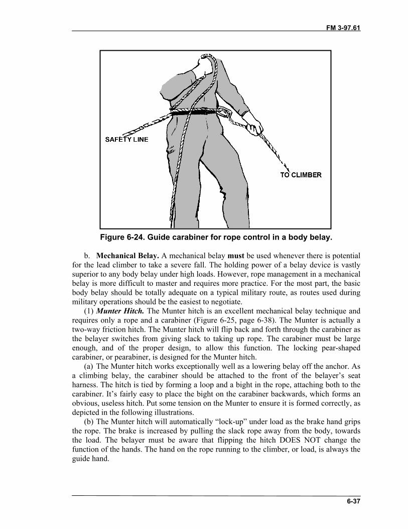
FM 3-97.61
6-37
Figure 6-24. Guide carabiner for rope control in a body belay.
b. Mechanical Belay. A mechanical belay must be used whenever there is potentialfor the lead climber to take a severe fall. The holding power of a belay device is vastlysuperior to any body belay under high loads. However, rope management in a mechanicalbelay is more difficult to master and requires more practice. For the most part, the basicbody belay should be totally adequate on a typical military route, as routes used duringmilitary operations should be the easiest to negotiate.
(1) Munter Hitch. The Munter hitch is an excellent mechanical belay technique andrequires only a rope and a carabiner (Figure 6-25, page 6-38). The Munter is actually atwo-way friction hitch. The Munter hitch will flip back and forth through the carabiner asthe belayer switches from giving slack to taking up rope. The carabiner must be largeenough, and of the proper design, to allow this function. The locking pear-shapedcarabiner, or pearabiner, is designed for the Munter hitch.
(a) The Munter hitch works exceptionally well as a lowering belay off the anchor. Asa climbing belay, the carabiner should be attached to the front of the belayer’s seatharness. The hitch is tied by forming a loop and a bight in the rope, attaching both to thecarabiner. It’s fairly easy to place the bight on the carabiner backwards, which forms anobvious, useless hitch. Put some tension on the Munter to ensure it is formed correctly, asdepicted in the following illustrations.
(b) The Munter hitch will automatically “lock-up” under load as the brake hand gripsthe rope. The brake is increased by pulling the slack rope away from the body, towardsthe load. The belayer must be aware that flipping the hitch DOES NOT change thefunction of the hands. The hand on the rope running to the climber, or load, is always theguide hand.

FM 3-97.61
6-38
Figure 6-25. Munter hitch.
(2) Figure-Eight Device. The figure-eight device is a versatile piece of equipmentand, though developed as a rappel device, has become widely accepted as an effectivemechanical belay device (Figure 6-26). The advantage of any mechanical belay is frictionrequired to halt a fall is applied on the rope through the device, rather than around thebelayer’s body. The device itself provides rope control for upward and downward pullsand excellent friction for halting severe falls. The main principle behind the figure-eightdevice in belay mode is the friction developing on the rope as it reaches and exceeds the90-degree angle between the rope entering the device and leaving the device. As a belaydevice, the figure-eight works well for both belayed climbing and for lowering personneland equipment on fixed-rope installations.
(a) As a climbing belay, a bight placed into the climbing rope is run through the“small eye” of the device and attached to a locking carabiner at the front of the belayer’sseat harness. A short, small diameter safety rope is used to connect the “large eye” of thefigure eight to the locking carabiner for control of the device. The guide hand is placedon the rope running to the climber. Rope management is performed as in a body belay.The brake is applied by pulling the slack rope in the brake hand towards the body,locking the rope between the device and the carabiner.
(b) As a lowering belay, the device is normally attached directly to the anchor withthe rope routed as in rappelling.

FM 3-97.61
6-39
Figure 6-26. Figure-eight device.
Note: Some figure-eight descenders should not be used as belay devices due to theirconstruction and design. Always refer to manufacturer’s specifications anddirections before use.
(3) Mechanical Camming Device. The mechanical camming device has an internalcamming action that begins locking the rope in place as friction is increased. Unlike theother devices, the mechanical camming device can stop a falling climber without anyinput from the belayer. A few other devices perform similarly to this, but have no movingparts. Some limitations to these type devices are minimum and maximum rope diameters.
(4) Other Mechanical Belay Devices. There are many other commercially availablemechanical belay devices. Most of these work with the same rope movement directionand the same braking principle. The air traffic controller (ATC), slotted plate, and othertube devices are made in many different shapes. These all work on the same principle asthe figure-eight device―friction increases on the rope as it reaches and exceeds the90-degree angle between the rope entering the device and leaving the device.
6-16. ESTABLISHING A BELAYA belay can be established using either a direct or indirect connection. Each type hasadvantages and disadvantages. The choice will depend on the intended use of the belay.
a. Direct Belay. The direct belay removes any possible forces from the belayer andplaces this force completely on the anchor. Used often for rescue installations or to bringa second climber up to a new belay position in conjunction with the Munter hitch, thebelay can be placed above the belayer’s stance, creating a comfortable position and easeof applying the brake. Also, if the second falls or weights the rope, the belayer is notlocked into a position. Direct belays provide no shock-absorbing properties from thebelayer’s attachment to the system as does the indirect belay; therefore, the belayer is aptto pay closer attention to the belaying process.
FM 3-97.61
6-40
b. Indirect Belay. An indirect belay, the most commonly used, uses a belay deviceattached to the belayer’s harness. This type of belay provides dynamic shock or weightabsorption by the belayer if the climber falls or weights the rope, which reduces the directforce on the anchor and prevents a severe shock load to the anchor.
6-17. SETTING UP A BELAYIn rock climbing, climbers must sometimes make do with marginal protection placementsalong a route, but belay positions must be made as “bombproof” as possible.Additionally, the belayer must set up the belay in relation to where the fall force willcome from and pay strict attention to proper rope management for the belay to beeffective. All belay positions are established with the anchor connection to the front ofthe harness. If the belay is correctly established, the belayer will feel little or no force ifthe climber falls or has to rest on the rope. Regardless of the actual belay technique used,five basic steps are required to set up a sound belay.
a. Select Position and Stance. Once the climbing line is picked, the belayer selectshis position. It’s best if the position is off to the side of the actual line, putting the belayerout of the direct path of a potential fall or any rocks kicked loose by the climber. Theposition should allow the belayer to maintain a comfortable, relaxed stance, as he couldbe in the position for a fairly long time. Large ledges that allow a well braced, sittingstance are preferred. Look for belay positions close to bombproof natural anchors. Theposition must at least allow for solid artificial placements.
b. Aim the Belay. With the belay position selected, the belay must now be “aimed.”The belayer determines where the rope leading to the climber will run and the directionthe force of a fall will likely come from. When a lead climber begins placing protection,the fall force on the belayer will be in some upward direction, and in line with the firstprotection placement. If this placement fails under load, the force on the belay could bestraight down again. The belayer must aim his belay for all possible load directions,adjusting his position or stance when necessary. The belay can be aimed through ananchor placement to immediately establish an upward pull; however, the belayer mustalways be prepared for the more severe downward fall force in the event intermediateprotection placements fail.
c. Anchor the Belay. For a climbing belay to be considered bombproof, the belayermust be attached to a solid anchor capable of withstanding the highest possible fall force.A solid natural anchor would be ideal, but more often the belayer will have to placepitons or chocks. A single artificial placement should never be considered adequate foranchoring a belay (except at ground level). Multiple anchor points capable of supportingboth upward and downward pulls should be placed. The rule of thumb is to place twoanchors for a downward pull and one anchor for an upward pull as a MINIMUM. Thefollowing key points also apply to anchoring belays.
(1) Each anchor must be placed in line with the direction of pull it is intended tosupport.
(2) Each anchor attachment must be rigged “independently” so a failure of one willnot shock load remaining placements or cause the belayer to be pulled out of position.
(3) The attachment between the anchor and the belayer must be snug to support thestance. Both belayer’s stance and belay anchors should absorb the force of a fall.

FM 3-97.61
6-41
(4) It is best for the anchors to be placed relatively close to the belayer with shortattachments. If the climber has to be tied-off in an emergency, say after a severe fall, thebelayer can attach a Prusik sling to the climbing rope, reach back, and connect the slingto one of the anchors. The load can be placed on the Prusik and the belayer can come outof the system to render help.
(5) The belayer can use either a portion of the climbing rope or slings of theappropriate length to connect himself to the anchors. It’s best to use the climbing ropewhenever possible, saving the slings for the climb. The rope is attached using eitherfigure eight loops or clove hitches. Clove hitches have the advantage of being easilyadjusted. If the belayer has to change his stance at some point, he can reach back with theguide hand and adjust the length of the attachment through the clove hitch as needed.
(6) The anchor attachments should also help prevent the force of a fall from“rotating” the belayer out of position. To accomplish this, the climbing rope must passaround the “guide-hand side” of the body to the anchors. Sling attachments are connectedto the belayer’s seat harness (or bowline-on-a-coil) on the guide-hand side.
(7) Arrangement of rope and sling attachments may vary according to the number andlocation of placements. Follow the guidelines set forth and remember the key points forbelay anchors; “in line”, “independent”, and “snug”. Figure 6-27 shows an example of acommon arrangement, attaching the rope to the two “downward” anchors and a sling tothe “upward” anchor. Note how the rope is connected from one of the anchors back to thebelayer. This is not mandatory, but often helps “line-up” the second attachment.
Figure 6-27. Anchoring a belay.
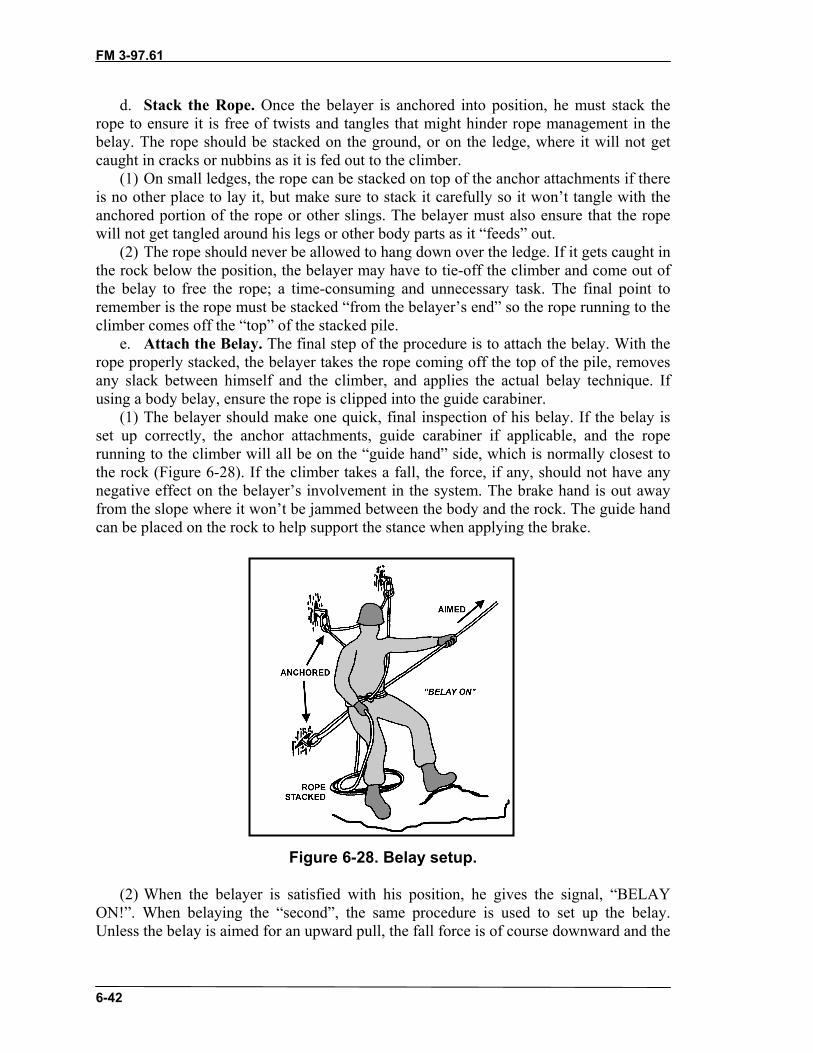
FM 3-97.61
6-42
d. Stack the Rope. Once the belayer is anchored into position, he must stack therope to ensure it is free of twists and tangles that might hinder rope management in thebelay. The rope should be stacked on the ground, or on the ledge, where it will not getcaught in cracks or nubbins as it is fed out to the climber.
(1) On small ledges, the rope can be stacked on top of the anchor attachments if thereis no other place to lay it, but make sure to stack it carefully so it won’t tangle with theanchored portion of the rope or other slings. The belayer must also ensure that the ropewill not get tangled around his legs or other body parts as it “feeds” out.
(2) The rope should never be allowed to hang down over the ledge. If it gets caught inthe rock below the position, the belayer may have to tie-off the climber and come out ofthe belay to free the rope; a time-consuming and unnecessary task. The final point toremember is the rope must be stacked “from the belayer’s end” so the rope running to theclimber comes off the “top” of the stacked pile.
e. Attach the Belay. The final step of the procedure is to attach the belay. With therope properly stacked, the belayer takes the rope coming off the top of the pile, removesany slack between himself and the climber, and applies the actual belay technique. Ifusing a body belay, ensure the rope is clipped into the guide carabiner.
(1) The belayer should make one quick, final inspection of his belay. If the belay isset up correctly, the anchor attachments, guide carabiner if applicable, and the roperunning to the climber will all be on the “guide hand” side, which is normally closest tothe rock (Figure 6-28). If the climber takes a fall, the force, if any, should not have anynegative effect on the belayer’s involvement in the system. The brake hand is out awayfrom the slope where it won’t be jammed between the body and the rock. The guide handcan be placed on the rock to help support the stance when applying the brake.
Figure 6-28. Belay setup.
(2) When the belayer is satisfied with his position, he gives the signal, “BELAYON!”. When belaying the “second”, the same procedure is used to set up the belay.Unless the belay is aimed for an upward pull, the fall force is of course downward and the
FM 3-97.61
6-43
belayer is usually facing away from the rock, the exception being a hanging belay on avertical face. If the rope runs straight down to the climber and the anchors are directlybehind the position, the belayer may choose to brake with the hand he feels mostcomfortable with. Anchor attachments, guide carabiner, and rope running to the climberthrough the guide hand must still be aligned on the same side to prevent the belayer frombeing rotated out of position, unless the belayer is using an improvised harness and theanchor attachment is at the rear.
6-18. TOP-ROPE BELAYA “top-rope” is a belay setup used in training to protect a climber while climbing onlonger, exposed routes. A solid, bombproof anchor is required at the top of the pitch. Thebelayer is positioned either on the ground with the rope running through the top anchorand back to the climber, or at the top at the anchor. The belayer takes in rope as theclimber proceeds up the rock. If this is accomplished with the belayer at the bottom, theinstructor can watch the belayer while he coaches the climber through the movements.
CAUTIONDo not use a body belay for top-rope climbing. Therope will burn the belayer if the climber has to belowered.
Section V. CLIMBING COMMANDSCommunication is often difficult during a climb. As the distance between climber andbelayer increases, it becomes harder to distinguish one word from another and theshortest sentence may be heard as nothing more than jumbled syllables. A series ofstandard voice commands were developed over the years to signal the essential ropemanagement functions in a belayed climb. Each command is concise and sounds a bitdifferent from another to reduce the risk of a misunderstanding between climber andbelayer. They must be pronounced clearly and loudly so they can be heard andunderstood in the worst conditions.
6-19. VERBAL COMMANDSTable 6-1, page 6-44, lists standard rope commands and their meanings in sequence asthey would normally be used on a typical climb. (Note how the critical “BELAY”commands are reversed so they sound different and will not be confused.)

FM 3-97.61
6-44
BELAYER CLIMBER MEANING/ACTION TAKEN“BELAY ON” The belay is on; you may climb when ready; the rope will
be managed as needed.“CLIMBING”(as a courtesy)
I am ready to climb.
“CLIMB”(as a courtesy)
Proceed, and again, the rope will be managed asnecessary.
“ROCK” “ROCK” PROTECT YOURSELF FROM FALLING OBJECTS.Signal will be echoed by all climbers in the area. Ifmultipitch climbing, ensure climbers below hear.
“TAKE ROPE” Take in excess rope between us without pulling me offthe route.
Belayer takes in rope.“SLACK” Release all braking/tension on the rope so I can have
slack without pulling the rope.
Belayer removes brake/tension.“TENSION” Take all the slack, apply brake, and hold me. My weight
will be on the rope.
Belayer removes slack and applies brake.“FALLING” I am falling.
Belayer applies brake to arrest the fall.“TWEN-TY-FIVE” You have approximately 25 feet of rope left. Start
looking for the next belay position.
Climber selects a belay position.“FIF-TEEN” You have approximately 15 feet of rope left. Start
looking for the next belay position.
Climber selects a belay position within the next few feet.“FIVE” Set up the belay. You have 5 feet of rope left. Set up the belay position.
You have no more rope.
Climber sets up the belay.Removes the belay,remains anchored.Prepares to climb.
“OFF BELAY” I have finished climbing and I am anchored. You mayremove the belay.
Belayer removes the belay and, remaining anchored,prepares to climb.
Table 6-1. Rope commands.
6-20. ROPE TUG COMMANDSSometimes the loudest scream cannot be heard when the climber and belayer are farapart. This is especially true in windy conditions, or when the climber is around a corner,above an overhang, or at the back of a ledge. It may be necessary to use a series of “tugs”on the rope in place of the standard voice commands. To avoid any possible confusionwith interpretation of multiple rope tug commands, use only one.
a. While a lead climb is in progress, the most important command is “BELAY ON.”This command is given only by the climber when the climber is anchored and is preparedfor the second to begin climbing. With the issue of this command, the second knows theclimber is anchored and the second prepares to climb.
b. For a rope tug command, the leader issues three distinct tugs on the rope AFTERanchoring and putting the second on belay. This is the signal for “BELAY ON” andsignals the second to climb when ready. The new belayer keeps slack out of the rope.

FM 3-97.61
6-45
Section VI. ROPED CLIMBING METHODSIn military mountaineering, the primary mission of a roped climbing team is to “fix” aroute with some type of rope installation to assist movement of less trained personnel inthe unit. This duty falls upon the most experienced climbers in the unit, usually workingin two- or three-man groups or teams called assault climbing teams. Even if the climbingis for another purpose, roped climbing should be performed whenever the terrainbecomes difficult and exposed.
6-21. TOP-ROPED CLIMBINGTop-roped climbing is used for training purposes only. This method of climbing is notused for movement due to the necessity of pre-placing anchors at the top of a climb. Ifyou can easily access the top of a climb, you can easily avoid the climb itself.
a. For training, top-roped climbing is valuable because it allows climbers to attemptclimbs above their skill level and or to hone present skills without the risk of a fall. Top-roped climbing may be used to increase the stamina of a climber training to climb longerroutes as well as for a climber practicing protection placements.
b. The belayer is positioned either at the base of a climb with the rope runningthrough the top anchor and back to the climber or at the top at the anchor. The belayertakes in rope as the climber moves up the rock, giving the climber the same protection asa belay from above. If this is accomplished with the belayer at the bottom, the instructoris able to keep an eye on the belayer while he coaches the climber through themovements.
6-22. LEAD CLIMBINGA lead climb consists of a belayer, a leader or climber, rope(s), and webbing or hardwareused to establish anchors or protect the climb. As he climbs the route, the leader emplaces“intermediate” anchors, and the climbing rope is connected to these anchors with acarabiner. These “intermediate” anchors protect the climber against a fall-thus the term“protecting the climb.”
Note: Intermediate anchors are commonly referred to as “protection,” “pro,” “pieces,”“pieces of pro,” “pro placements,” and so on. For standardization within thispublication, these specific anchors will be referred to as “protection;” anchorsestablished for other purposes, such as rappel points, belays, or other ropeinstallations, will be referred to as “anchors.”
CAUTIONDuring all lead climbing, each climber in the team iseither anchored or being belayed.
a. Lead climbing with two climbers is the preferred combination for movement ontechnically difficult terrain. Two climbers are at least twice as fast as three climbers, andare efficient for installing a “fixed rope,” probably the most widely used rope installation

FM 3-97.61
6-46
in the mountains. A group of three climbers are typically used on moderate snow, ice, andsnow-covered glaciers where the rope team can often move at the same time, stoppingoccasionally to set up belays on particularly difficult sections. A group or team of threeclimbers is sometimes used in rock climbing because of an odd number of personnel, ashortage of ropes (such as six climbers and only two ropes), or to protect and assist anindividual who has little or no experience in climbing and belaying. Whichever techniqueis chosen, a standard roped climbing procedure is used for maximum speed and safety.
b. When the difficulty of the climbing is within the “leading ability” of bothclimbers, valuable time can be saved by “swinging leads.” This is normally the mostefficient method for climbing multipitch routes. The second finishes cleaning the firstpitch and continues climbing, taking on the role of lead climber. Unless he requiresequipment from the other rack or desires a break, he can climb past the belay andimmediately begin leading. The belayer simply adjusts his position, re-aiming the belayonce the new leader begins placing protection. Swinging leads, or “leap frogging,” shouldbe planned before starting the climb so the leader knows to anchor the upper belay forboth upward and downward pulls during the setup.
c. The procedures for conducting a lead climb with a group of two are relativelysimple. The most experienced individual is the “lead” climber or leader, and isresponsible for selecting the route. The leader must ensure the route is well within hisability and the ability of the second. The lead climber carries most of the climbingequipment in order to place protection along the route and set up the next belay. Theleader must also ensure that the second has the necessary equipment, such as a pitonhammer, nut tool, etc., to remove any protection that the leader may place.
(1) The leader is responsible for emplacing protection frequently enough and in sucha manner that, in the event that either the leader or the second should fall, the fall will beneither long enough nor hard enough to result in injury. The leader must also ensure thatthe rope is routed in a way that will allow it to run freely through the protectionplacements, thus minimizing friction, or “rope drag”.
(2) The other member of the climbing team, the belayer (sometimes referred to as the“second”), is responsible for belaying the leader, removing the belay anchor, andretrieving the protection placed by the leader between belay positions (also called“cleaning the pitch”).
(3) Before the climb starts, the second will normally set up the first belay while theleader is arranging his rack. When the belay is ready, the belayer signals, “BELAY ON”,affirming that the belay is “on” and the rope will be managed as necessary. When theleader is ready, he double checks the belay. The leader can then signal, “CLIMBING”,only as a courtesy, to let the belayer know he is ready to move. The belayer can replywith “CLIMB”, again, only as a courtesy, reaffirming that the belay is “on” and the ropewill be managed as necessary. The leader then begins climbing.
(4) While belaying, the second must pay close attention to the climber’s every move,ensuring that the rope runs free and does not inhibit the climber’s movements. If hecannot see the climber, he must “feel” the climber through the rope. Unless toldotherwise by the climber, the belayer can slowly give slack on the rope as the climberproceeds on the route. The belayer should keep just enough slack in the rope so theclimber does not have to pull it through the belay. If the climber wants a tighter rope, itcan be called for. If the belayer notices too much slack developing in the rope, the excess

FM 3-97.61
6-47
rope should be taken in quickly. It is the belayer’s responsibility to manage the rope,whether by sight or feel, until the climber tells him otherwise.
(5) As the leader protects the climb, slack will sometimes be needed to place the ropethrough the carabiner (clipping), in a piece of protection above the tie-in point on theleaders harness. In this situation, the leader gives the command “SLACK” and thebelayer gives slack, (if more slack is needed the command will be repeated). The leader isable to pull a bight of rope above the tie-in point and clip it into the carabiner in theprotection above. When the leader has completed the connection, or the clip, thecommand “TAKE ROPE” is given by the leader and the belayer takes in the remainingslack.
(6) The leader continues on the route until either a designated belay location isreached or he is at the end of or near the end of the rope. At this position, the leader setsan anchor, connects to the anchor and signals “OFF BELAY”. The belayer prepares toclimb by removing all but at least one of his anchors and secures the remainingequipment. The belayer remains attached to at least one anchor until the command“BELAY ON” is given.
d. When the leader selects a particular route, he must also determine how much, andwhat types, of equipment might be required to safely negotiate the route. The selectedequipment must be carried by the leader. The leader must carry enough equipment tosafely protect the route, additional anchors for the next belay, and any other items to becarried individually such as rucksacks or individual weapons.
(1) The leader will assemble, or “rack,” the necessary equipment onto his harness oronto slings around the head and shoulder. A typical leader “rack” consists of:
• Six to eight small wired stoppers on a carabiner.• Four to six medium to large wired stoppers on a carabiner.• Assorted hexentrics, each on a separate carabiner.• SLCDs of required size, each on a separate carabiner.• Five to ten standard length runners, with two carabiners on each.• Two to three double length runners, with two carabiners on each.• Extra carabiners.• Nut tool.
Note: The route chosen will dictate, to some degree, the necessary equipment. Membersof a climbing team may need to consolidate gear to climb a particular route.
(2) The belayer and the leader both should carry many duplicate items whileclimbing.
• Short Prusik sling.• Long Prusik sling.• Cordellette.• 10 feet of 1-inch webbing.• 20 feet of 1-inch webbing.• Belay device (a combination belay/rappel device is multifunctional).• Rappel device (a combination belay/rappel device is multifunctional).• Large locking carabiner (pear shape carabiners are multifunctional).
FM 3-97.61
6-48
• Extra carabiners.• Nut tool (if stoppers are carried).
Note: If using an over the shoulder gear sling, place the items in order from smallest tothe front and largest to the rear.
e. Leading a difficult pitch is the most hazardous task in roped climbing. The leadclimber may be exposed to potentially long, hard falls and must exercise keen judgmentin route selection, placement of protection, and routing of the climbing rope through theprotection. The leader should try to keep the climbing line as direct as possible to the nextbelay to allow the rope to run smoothly through the protection with minimal friction.Protection should be placed whenever the leader feels he needs it, and BEFORE movingpast a difficult section.
CAUTIONThe climber must remember he will fall twice thedistance from his last piece of protection before therope can even begin to stop him.
(1) Placing Protection. Generally, protection is placed from one stable position to thenext. The anchor should be placed as high as possible to reduce the potential fall distancebetween placements. If the climbing is difficult, protection should be placed morefrequently. If the climbing becomes easier, protection can be placed farther apart, savinghardware for difficult sections. On some routes an extended diagonal or horizontalmovement, known as a traverse, is required. As the leader begins this type of move, hemust consider the second’s safety as well as his own. The potential fall of the second willresult in a pendulum swing if protection is not adequate to prevent this. The dangercomes from any objects in the swinging path of the second.
CAUTIONLeader should place protection prior to, during, andupon completion of any traverse. This will minimizethe potential swing, or pendulum, for both the leaderand second if either should fall.
(2) Correct Clipping Technique. Once an anchor is placed, the climber “clips” therope into the carabiner (Figure 6-29, page 6-50). As a carabiner hangs from theprotection, the rope can be routed through the carabiner in two possible ways. One waywill allow the rope to run smoothly as the climber moves past the placement; the otherway will often create a dangerous situation in which the rope could become “unclipped”from the carabiner if the leader were to fall on this piece of protection. In addition, a

FM 3-97.61
6-49
series of incorrectly clipped carabiners may contribute to rope drag. When placingprotection, the leader must ensure the carabiner on the protection does not hang with thecarabiner gate facing the rock; when placing protection in a crack ensure the carabinergate is not facing into the crack.
• Grasp the rope with either hand with the thumb pointing down the ropetowards the belayer
• Pull enough rope to reach the carabiner with a bight• Note the direction the carabiner is hanging from the protection• Place the bight into the carabiner so that, when released, the rope does not
cause the carabiner to twist.(a) If the route changes direction, clipping the carabiner will require a little more
thought. Once leaving that piece of protection, the rope may force the carabiner to twist ifnot correctly clipped. If the clip is made correctly, a rotation of the clipped carabiner toensure that the gate is not resting against the rock may be all that is necessary.
CAUTIONEnsure the carabiner gate is not resting against aprotrusion or crack edge in the rock surface; the rockmay cause the gate to open.
(b) Once the rope is clipped into the carabiner, the climber should check to see that itis routed correctly by pulling on the rope in the direction it will travel when the climbermoves past that position.
(c) Another potential hazard peculiar to leading should be eliminated before theclimber continues. The carabiner is attached to the anchor or runner with the gate facingaway from the rock and opening down for easy insertion of the rope. However, in aleader fall, it is possible for the rope to run back over the carabiner as the climber fallsbelow the placement. If the carabiner is left with the gate facing the direction of the routethere is a chance that the rope will open the gate and unclip itself entirely from theplacement. To prevent this possibility, the climber should ensure that after the clip hasbeen made, the gate is facing away from the direction of the route. There are two ways toaccomplish this: determine which direction the gate will face before the protection orrunner is placed or once clipped, rotate the carabiner upwards 180 degrees. This problemis more apt to occur if bent gate carabiners are used. Straight gate ovals or “Ds” are lesslikely to have this problem and are stronger and are highly recommended. Bent gatecarabiners are easier to clip the rope into and are used mostly on routes with boltspreplaced for protection. Bent gate carabiners are not recommended for many climbingsituations.

FM 3-97.61
6-50
Figure 6-29. Clipping on to protection.
(3) Reducing Rope Drag; Using Runners. No matter how direct the route, theclimber will often encounter problems with “rope drag” through the protection positions.The friction created by rope drag will increase to some degree every time the rope passesthrough a carabiner, or anchor. It will increase dramatically if the rope begins to “zigzag”as it travels through the carabiners. To prevent this, the placements should be positionedso the rope creates a smooth, almost straight line as it passes through the carabiners(Figure 6-30). Minimal rope drag is an inconvenience; severe rope drag may actually pullthe climber off balance, inducing a fall.
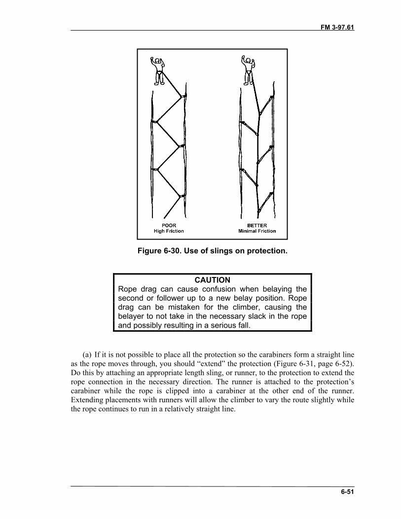
FM 3-97.61
6-51
Figure 6-30. Use of slings on protection.
CAUTIONRope drag can cause confusion when belaying thesecond or follower up to a new belay position. Ropedrag can be mistaken for the climber, causing thebelayer to not take in the necessary slack in the ropeand possibly resulting in a serious fall.
(a) If it is not possible to place all the protection so the carabiners form a straight lineas the rope moves through, you should “extend” the protection (Figure 6-31, page 6-52).Do this by attaching an appropriate length sling, or runner, to the protection to extend therope connection in the necessary direction. The runner is attached to the protection’scarabiner while the rope is clipped into a carabiner at the other end of the runner.Extending placements with runners will allow the climber to vary the route slightly whilethe rope continues to run in a relatively straight line.

FM 3-97.61
6-52
Figure 6-31. Use of slings to extend placement positions.
(b) Not only is rope drag a hindrance, it can cause undue movement of protection asthe rope tightens between any “out of line” placements. Rope drag through chockplacements can be dangerous. As the climber moves above the placements, an outward orupward pull from rope drag may cause correctly set chocks to pop out, even when used“actively”. Most all chocks placed for leader protection should be extended with a runner,even if the line is direct to eliminate the possibility of movement.
(c) Wired chocks are especially prone to wiggling loose as the rope pulls on the stiffcable attachment. All wired chocks used for leader protection should be extended toreduce the chance of the rope pulling them out (Figure 6-32). Some of the larger chocks,such as roped Hexentrics and Tri-Cams, have longer slings pre-attached that willnormally serve as an adequate runner for the placement. Chocks with smaller slingattachments must often be extended with a runner. Many of today’s chocks aremanufactured with pre-sewn webbing installed instead of cable.
Figure 6-32. Use of sling on a wired stopper.

FM 3-97.61
6-53
(d) When a correctly placed piton is used for protection, it will normally not beaffected by rope drag. A correctly placed piton is generally a multi-directional anchor,therefore, rope drag through pitons will usually only affect the leader’s movements butwill continue to protect as expected.
(e) Rope drag will quite often move SLCDs out of position, or “walk” them deeperinto the crack than initially placed, resulting in difficult removal or inability to removethem at all. Furthermore, most cases of SLCD movement result in the SLCD moving to aposition that does not provide protection in the correct direction or no protection at alldue to the lobes being at different angles from those at the original position.
Note: Any placement extended with a runner will increase the distance of a potential fallby the actual length of the sling. Try to use the shortest runners possible, ensuringthey are long enough to function properly.
f. Belaying the follower is similar to belaying a top-roped climb in that the followeris not able to fall any farther than rope stretch will allow. This does not imply there is nodanger in following. Sharp rocks, rock fall, and inadequately protected traverses canresult in damage to equipment or injury to the second.
g. Following, or seconding, a leader has a variety of responsibilities. The second hasto issue commands to the leader, as well as follow the leader’s commands. Once the leadclimber reaches a good belay position, he immediately establishes an anchor andconnects to it. When this is completed he can signal “OFF BELAY” to the belayer. Thesecond can now remove the leader’s belay and prepare to climb. The second must remainattached to at least one of the original anchors while the leader is preparing the next belayposition. The removed materials and hardware can be organized and secured on thesecond’s rack in preparation to climb.
(1) When the leader has established the new belay position and is ready to belay thefollower, the “new” belayer signals “BELAY ON.” The second, now the climber,removes any remaining anchor hardware/materials and completes any final preparations.The belayer maintains tension on the rope, unless otherwise directed, while the finalpreparations are taking place, since removal of these remaining anchors can introduceslack into the rope. When the second is ready, he can, as a courtesy, signal“CLIMBING,” and the leader can, again as a courtesy, reply with “CLIMB.”
(2) Upon signaling “BELAY ON,” the belayer must remove and keep all slack fromthe rope. (This is especially important as in many situations the belayer cannot see thefollower. A long pitch induces weight and sometimes “drag” on the rope and the belayerabove will have difficulty distinguishing these from a rope with no slack.)
h. When removing protection, the man cleaning the pitch should rack it properly tofacilitate the exchange and or arrangement of equipment at the end of the pitch. Whenremoving the protection, or “cleaning the pitch”, SLCDs or chocks may be left attachedto the rope to prevent loss if they are accidentally dropped during removal. If necessary,the hardware can remain on the rope until the second reaches a more secure stance. Ifremoving a piton, the rope should be unclipped from the piton to avoid the possibility ofdamaging the rope with a hammer strike.
(1) The second may need to place full body weight on the rope to facilitate use ofboth hands for protection removal by giving the command “TENSION.” The second

FM 3-97.61
6-54
must also ensure that he does not climb faster than the rope is being taken in by thebelayer. If too much slack develops, he should signal “TAKE ROPE” and wait until theexcess is removed before continuing the climb. Once the second completes the pitch, heshould immediately connect to the anchor. Once secured, he can signal “OFF BELAY.”The leader removes the belay, while remaining attached to an anchor. The equipment isexchanged or organized in preparation for the next pitch or climb.
(2) When the difficulty of the climbing is within the “leading ability” of bothclimbers, valuable time can be saved by “swinging leads.” This is normally the mostefficient method for climbing multi-pitch routes. The second finishes cleaning the firstpitch and continues climbing, taking on the role of lead climber. Unless he requiresequipment from the belayer or desires a break, he can climb past the belay andimmediately begin leading. The belayer simply adjusts his position, re-aiming the belayonce the new leader begins placing protection. Swinging leads, or “leap frogging,” shouldbe planned before starting the climb so the leader knows to anchor the upper belay forboth upward and downward pulls during the setup.
6-23. AID CLIMBINGWhen a route is too difficult to free climb and is unavoidable, if the correct equipment isavailable you might aid climb the route. Aid climbing consists of placing protection andputting full body weight on the piece. This allows you to hang solely on the protectionyou place, giving you the ability to ascend more difficult routes than you can free climb.Clean aid consists of using SLCDs and chocks, and is the simplest form of aid climbing.
a. Equipment. Aid climbing can be accomplished with various types of protection.Regardless of the type of protection used, the method of aid climbing is the same. Inaddition to the equipment for free climbing, other specialized equipment will be needed.
(1) Pitons. Pitons are used the same as for free climbing. Most piton placements willrequire the use of both hands. Piton usage will usually leave a scar in the rock just byvirtue of the hardness of the piton and the force required to set it with a hammer.Swinging a hammer to place pitons will lead to climber fatigue sooner than clean aid.Since pitons are multidirectional, the strength of a well-placed piton is more secure thanmost clean aid protection. Consider other forms of protection when noise could behazardous to tactics.
(2) Bolts. Bolts are used when no other protection will work. They are a morepermanent form of protection and more time is needed to place them. Placing boltscreates more noise whether drilled by hand or by motorized drill. Bolts used in climbingare a multi-part expanding system pounded into predrilled holes and then tightened to thedesired torque with a wrench or other tool. Bolts are used in many ways in climbingtoday. The most common use is with a hanger attached and placed for anchors in faceclimbing. However, bolts can be used for aid climbing, with or without the hanger.
(a) Placing bolts for aid climbing takes much more time than using pitons or cleanaid. Bolting for aid climbing consists of consecutive bolts about 2 feet apart. Drilling adeep enough hole takes approximately thirty minutes with a hand drill and up to twominutes with a powered hammer drill. A lot of time and work is expended in a shortdistance no matter how the hole is drilled. (The weight of a powered hammer drillbecomes an issue in itself.) Noise will also be a factor in both applications. A constantpounding with a hammer on the hand drill or the motorized pounding of the powered drill

FM 3-97.61
6-55
may alert the enemy to the position. The typical climbing bolt/hanger combinationnormally is left in the hole where it was placed.
(b) Other items that can be used instead of the bolt/hanger combination are theremovable and reusable “spring-loaded removable bolts” such as rivets (hex headthreaded bolts sized to fit tightly into the hole and pounded in with a hammer), split-shaftrivets, and some piton sizes that can be pounded into the holes. When using rivets or boltswithout a hanger, place a loop of cable over the head and onto the shaft of the rivet orbolt and attach a carabiner to the other end of the loop (a stopper with the chock slid backwill suffice). Rivet hangers are available that slide onto the rivet or bolt after it is placedand are easily removed for reuse. Easy removal means a slight loss of security while inuse.
(3) SLCDs. SLCDs are used the same as for free climbing, although in aid climbing,full body weight is applied to the SLCD as soon as it is placed.
(4) Chocks. Chocks are used the same as for free climbing, although in aid climbing,weight is applied to the chock as soon as it is placed.
(5) Daisy Chains. Daisy chains are tied or presewn loops of webbing with small tiedor presewn loops approximately every two inches. The small loops are just large enoughfor two or three carabiners. Two daisy chains should be girth-hitched to the tie-in point inthe harness.
(6) Etriers (or Aiders). Etriers (aiders) are tied or presewn webbing loops with four tosix tied or presewn internal loops, or steps, approximately every 12 inches. The internalloops are large enough to easily place one booted foot into. At least two etriers (aiders)should be connected by carabiner to the free ends of the daisy chains.
(7) Fifi Hook. A fifi hook is a small, smooth-surfaced hook strong enough for bodyweight. The fifi hook should be girth-hitched to the tie-in point in the harness and is usedin the small loops of the daisy chain. A carabiner can be used in place of the fifi hook,although the fifi hook is simpler and adequate.
(8) Ascenders. Ascenders are mechanical devices that will move easily in onedirection on the rope, but will lock in place if pushed or pulled the other direction.(Prusiks can be used but are more difficult than ascenders.)
b. Technique. The belay will be the same as in normal lead climbing and the ropewill be routed through the protection the same way also. The big difference is themovement up the rock. With the daisy chains, aiders, and fifi hook attached to the ropetie-in point of the harness as stated above, and secured temporarily to a gear loop or gearsling, the climb continues as follows:
(1) The leader places the first piece of protection as high as can safely be reached andattaches the appropriate sling/carabiner
(2) Attach one daisy chain/aider group to the newly placed protection(3) Clip the rope into the protection, (the same as for normal lead climbing) (4) Insure the protection is sound by weighting it gradually; place both feet, one at a
time, into the steps in the aider, secure your balance by grasping the top of the aider withyour hands.
(5) When both feet are in the aider, move up the steps until your waist is no higherthan the top of the aider.
(6) Place the fifi hook (or substituted carabiner) into the loop of the daisy chainclosest to the daisy chain/aider carabiner, this effectively shortens the daisy chain;
FM 3-97.61
6-56
maintain tension on the daisy chain as the hook can fall out of the daisy chain loop if it isunweighted.
Note: Moving the waist higher than the top of the aider is possible, but this creates apotential for a fall to occur even though you are on the aider and “hooked” closeto the protection with the daisy chain. As the daisy chain tie-in point on theharness moves above the top of the aider, you are no longer supported from aboveby the daisy chain, you are now standing above your support. From this height,the fifi hook can easily fall out of the daisy chain loop if it is unweighted. If thishappens, you could fall the full length of the daisy chain resulting in a static fallon the last piece of protection placed.
(7) Release one hand from the aider and place the next piece of protection, again, ashigh as you can comfortably reach; if using pitons or bolts you may need both hands free-“lean” backwards slowly, and rest your upper body on the daisy chain that you have“shortened” with the fifi hook
(8) Clip the rope into the protection (9) Attach the other daisy chain/aider group to the next piece of protection(10) Repeat entire process until climb is finishedc. Seconding. When the pitch is completed, the belayer will need to ascend the
route. To ascend the route, use ascenders instead of Prusiks, ascenders are much fasterand safer than Prusiks. Attach each ascender to a daisy chain/aider group with carabiners.To adjust the maximum reach/height of the ascenders on the rope, adjust the effectivelength of the daisy chains with a carabiner the same as with the fifi hook; the typicalheight will be enough to hold the attached ascender in the hand at nose level. Whenadjusted to the correct height, the arms need not support much body weight. If theascender is too high, you will have difficulty reaching and maintaining a grip on thehandle.
(1) Unlike lead climbing, there will be a continuous load on the rope during thecleaning of the route, this would normally increase the difficulty of removing protection.To make this easier, as you approach the protection on the ascenders, move theascenders, one at a time, above the piece. When your weight is on the rope above thepiece, you can easily unclip and remove the protection.
CAUTIONIf both ascenders should fail while ascending thepitch, a serious fall could result. To prevent thispossibility, tie-in short on the rope every 10-20 feet bytying a figure eight loop and clipping it into theharness with a separate locking carabiner as soon asthe ascent is started. After ascending another 20 feet,repeat this procedure. Do not unclip the previousfigure eight until the new knot is attached to anotherlocking carabiner. Clear each knot as you unclip it.

FM 3-97.61
6-57
Notes: 1. Ensure the loops formed by the short tie-ins do not catch on anything below asyou ascend.
2. If the nature of the rock will cause the “hanging loop” of rope, formed bytying in at the end of the rope, to get caught as you move upward, do not tieinto the end of the rope.
(2) Seconding an aid pitch can be done in a similar fashion as seconding free-climbedpitches. The second can be belayed from above as the second “climbs” the protection.However, the rope is unclipped from the protection before the aider/daisy chain isattached.
d. Seconding Through a Traverse. While leading an aid traverse, the climber ishanging on the protection placed in front of the current position. If the second were toclean the section by hanging on the rope while cleaning, the protection will be pulled inmore than one direction, possibly resulting in the protection failing. To make this saferand easier, the second should hang on the protection just as the leader did. As the secondmoves to the beginning of the traverse, one ascender/daisy chain/aider group is removedfrom the rope and clipped to the protection with a carabiner, (keep the ascenders attachedto the daisy chain/aider group for convenience when the traverse ends). The second willnegotiate the traverse by leapfrogging the daisy chain/aider groups on the next protectionjust as the leader did. Cleaning is accomplished by removing the protection as it is passedwhen all weight is removed from it. This is in effect a self-belay. The second maintains ashorter safety tie-in on the rope than for vertical movement to reduce the possibility of alengthy pendulum if the protection should pull before intended.
e. Clean Aid Climbing. Clean aid climbing consists of using protection placedwithout a hammer or drill involvement: chocks, SLCDs, hooks, and other protectionplaced easily by hand. This type of aid climbing will normally leave no trace of the climbwhen completed. When climbing the aiders on clean aid protection, ensure the protectiondoes not “move” from it’s original position.
(1) Hooks are any device that rests on the rock surface without a camming orgripping action. Hooks are just what the name implies, a curved piece of hard steel with ahole in one end for webbing attachment. The hook blade shape will vary from one modelto another, some have curved or notched “blades” to better fit a certain crystal shape on aface placement. These types of devices due to their passive application, are only securewhile weighted by the climber.
(2) Some featureless sections of rock can be negotiated with hook use, although boltscan be used. Hook usage is faster and quieter but the margin of safety is not there unlesshooks are alternated with more active forms of protection. If the last twenty foot sectionof a route is negotiated with hooks, a forty foot fall could result.
6-24. THREE-MAN CLIMBING TEAMOften times a movement on steep terrain will require a team of more than two climbers,which involves more difficulties. A four-man team (or more) more than doubles thedifficulty found in three men climbing together. A four-man team should be broken downinto two groups of two unless prevented by a severe lack of gear.

FM 3-97.61
6-58
a. Given one rope, a three-man team is at a disadvantage on a steep, belayed climb.It takes at least twice as long to climb an average length pitch because of the thirdclimber and the extra belaying required. The distance between belay positions will behalved if only one rope is used because one climber must tie in at the middle of the rope.Two ropes are recommended for a team of three climbers.
Note: Time and complications will increase when a three-man team uses only one rope.For example: a 100-foot climb with a 150-foot rope would normally require twobelays for two climbers; a 100-foot climb with a 150-foot rope would require sixbelays for three climbers.
b. At times a three-man climb may be unavoidable and personnel should be familiarwith the procedure. Although a team of three may choose from many different methods,only two are described below. If the climb is only one pitch, the methods will vary.
CAUTIONWhen climbing with a team of three, protectedtraverses will require additional time. The equipmentused to protect the traverse must be left in place toprotect both the second and third climbers.
(1) The first method can be used when the belay positions are not large enough forthree men. If using one rope, two climbers tie in at each end and the other at the midpoint. When using two ropes, the second will tie in at one end of both ropes, and the othertwo climbers will each tie in to the other ends. The most experienced individual is theleader, or number 1 climber. The second, or number 2 climber, is the stronger of theremaining two and will be the belayer for both number 1 and number 3. Number 3 will bethe last to climb. Although the number 3 climber does no belaying in this method, eachclimber should be skilled in the belay techniques required. The sequence for this method(in one pitch increments) is as follows (repeated until the climb is complete):
(a) Number 1 ascends belayed by number 2. Number 2 belays the leader up the firstpitch while number 3 is simply anchored to the rock for security (unless starting off atground level) and manages the rope between himself and number 2. When the leadercompletes the pitch, he sets up the next belay and belays number 2 up.
(b) Number 2 ascends belayed by number 1, and cleans the route (except fortraverses). Number 2 returns the hardware to the leader and belays him up the next pitch.When the leader completes this pitch, he again sets up a new belay. When number 2receives “OFF BELAY” from the leader, he changes ropes and puts number 3 on belay.He should not have to change anchor attachments because the position was already aimedfor a downward as well as an upward pull when he belayed the leader.
(c) Number 3 ascends belayed by number 2. When number 3 receives “BELAY ON,”he removes his anchor and climbs to number 2’s position. When the pitch is completed hesecures himself to one of number 2’s belay anchors. When number 1’s belay is ready, he

FM 3-97.61
6-59
brings up number 2 while number 3 remains anchored for security. Number 2 againcleans the pitch and the procedure is continued until the climb is completed.
(d) In this method, number 3 performs no belay function. He climbs when told to doso by number 2. When number 3 is not climbing, he remains anchored to the rock forsecurity. The standard rope commands are used; however, the number 2 climber mayinclude the trailing climber’s name or number in the commands to avoid confusion as towho should be climbing.
(d) Normally, only one climber would be climbing at a time; however, the number 3climber could ascend a fixed rope to number 2’s belay position using proper ascendingtechnique, with no effect on the other two members of the team. This would save time fora team of three, since number 2 would not have to belay number 3 and could be eitherbelaying number 1 to the next belay or climbing to number 1. If number 3 is to ascend afixed rope to the next belay position, the rope will be loaded with number 3’s weight, andpositioned directly off the anchors established for the belay. The rope should be locatedso it does not contact any sharp edges. The rope to the ascending number 3 could besecured to a separate anchor, but this would require additional time and gear.
(2) The second method uses either two ropes or a doubled rope, and number 2 andnumber 3 climb simultaneously. This requires either a special belay device that acceptstwo ropes, such as the tuber type, or with two Munter hitches. The ropes must travelthrough the belay device(s) without affecting each other.
(a) As the leader climbs the pitch, he will trail a second rope or will be tied in with afigure eight in the middle of a doubled rope. The leader reaches the next belay positionand establishes the anchor and then places both remaining climbers on belay. Oneremaining climber will start the ascent toward the leader and the other will start when agap of at least 10 feet is created between the two climbers. The belayer will have toremain alert for differences in rope movement and the climbers will have to climb at thesame speed. One of the “second” climbers also cleans the pitch.
(b) Having at least two experienced climbers in this team will also save time. Thebelayer will have additional requirements to meet as opposed to having just one second.The possible force on the anchor will be twice that of one second. The second that is notcleaning the pitch can climb off route, but staying on route will usually prevent a possibleswing if stance is not maintained.

FM 3-97.61(TC 90-6-1)
7-1
CHAPTER 7ROPE INSTALLATIONS
Obstacles on the battlefield today are inevitable. They can limit thebattlefield and, even worse, prevent a unit from accomplishing its mission.However, with highly skilled personnel trained on rope installations, leaderscan be assured that even a unit with limited mountain skills and experiencewill be able to successfully move and operate in terrain that would otherwisehave been impassable.
Section I. FIXED ROPEA fixed rope is a rope anchored in place to assist soldiers in movement over difficultterrain. Its simplest form is a rope tied off on the top of steep terrain. As terrain becomessteeper or more difficult, fixed rope systems may require intermediate anchors along theroute. Moving on a fixed rope requires minimal equipment. The use of harnesses,ascenders, and other technical gear makes fixed rope movement easier, faster, and safer,but adds to total mission weight.
7-1. INSTALLATIONTo install a fixed rope, two experienced climbers rope up for a roped climb. The leadermust have the necessary equipment to rig the anchor at the top of the pitch. Althoughleader protection is usually not needed on a typical slope, additional hardware can bebrought along and placed at the leader’s discretion. The second will establish a belay ifprotection is being placed. Otherwise, he will stack and manage the rope. He ensures therope runs smoothly up the slope and does not get tangled as the climber ascends. Uponreaching the end of the pitch, the leader will establish the top anchor. Once the anchor isrigged, the leader will take up any remaining slack between himself and the second. Hewill anchor the installation rope and remain tied into the rope. The second unties from hisend of the rope and begins to climb. If the leader placed protection, the second will cleanthe pitch on his way up.
7-2. UTILIZATIONAll personnel using the fixed rope grasp the rope with the palm downward and use it forassistance as they ascend the slope (Figure 7-1, page 7-2). An individual can easilyprevent a long fall by attaching himself to the rope with a sling using a friction knot (forexample, Prusik, autoblock). The knot is slid along the rope as the individual ascends. Ifthe climber slips and loses control of the rope, the friction knot will grab the rope andarrest the fall. The friction knot used in this manner is referred to as a self-belay (Figure7-2, page 7-2).

FM 3-97.61
7-2
Figure 7-1. Using a fixed rope.
Figure 7-2. Using a self-belay.
7-3. RETRIEVALIf the fixed rope is to be used on the descent, it can be left in place and recovered after thelast rappel. If not, the last climber will tie into the rope and be belayed from above. Theclimber now can easily free the rope if it gets caught on anything as it is taken up fromthe belayer.

FM 3-97.61
7-3
7-4. FIXED ROPE WITH INTERMEDIATE ANCHORSWhenever the route varies from the fall line of the slope, the fixed rope must be anchoredat intermediate anchor points (Figure 7-3). Intermediate anchor points should also beused on any long routes that exceed the length of a single rope. The use of intermediateanchor points creates independent sections and allows for changes in direction from onesection to the next. The independent sections allow for more personnel to move on thefixed rope. This type of fixed rope is commonly used along exposed ridges and narrowmountain passes.
Figure 7-3. Fixed rope with intermediate anchors.
FM 3-97.61
7-4
a. Installation. Two experienced climbers prepare for a roped climb. The leader willcarry a typical rack with enough hardware to place an adequate number of intermediateanchor points. The second sets up a standard belay. The route they select must have thefollowing characteristics:
• Most suitable location, ease of negotiation, avoids obstacles.• Availability of anchors (natural and artificial).• Area is safe from falling rock or ice.• Tactical considerations are met.• A rope routed between knee and chest height (waist high preferred).• Rope crossovers should be avoided.
As the leader climbs the route, he will place the anchors and route the climbing rope as ina typical roped climb. The leader makes use of any available natural anchors.
Note: Sling attachments should be kept as short and snug as possible to ensure that aload on the fixed rope below the anchor is placed only on that anchor. This willprevent one section from affecting another section.
(1) The leader places an anchor at all points where a change of direction occurs. Healso makes every attempt to route the rope so personnel will not have to cross back andforth over the rope between sections.
(2) When the leader reaches the end of the pitch, he temporarily anchors the rope. Heshould use a sling to anchor himself if there is any chance of slipping and falling. He thentakes up any excess slack, and attaches the rope to the anchor.
Note: Enough slack must be left in the rope so the second can tie the knots necessary tofix the rope.
(3) The second unties from the rope and anchors it at the bottom. He attaches himselfto the rope with a sling using a friction knot to create a self-belay. The self-belay willprotect the second as he climbs and fixes the rope to the intermediate anchor points.When he reaches an anchor point, he unclips the climbing rope so he can advance theself-belay beyond the anchor point. He then takes the slack out of the section below theanchor point. He ensures that the fixed rope will be approximately knee to chest level asclimbers negotiate the installation. He then attaches the rope using an anchor knot (forexample, middle-of-the-rope clove hitch, double figure-eight). The second then moves tonext anchor point and repeats the process.
(4) If a long runner is to be used at any anchor point, the second should adjust thesection below it so the runner is oriented in the direction where the load or pull on theanchor will come from. This will help isolate the section.
(5) The sections are normally adjusted fairly snug between anchor points. A slacksection may be necessary to move around obstacles in the route or large bulges in theterrain. If clove hitches are used, adjusting the clove hitches at each end of the section canleave any amount of slack.
(6) A middle-of-the-rope Prusik safetied with a figure eight may be used when utilityropes are available. These are used to adjust the rope height (either higher or lower).
FM 3-97.61
7-5
(7) In addition to the fixed rope, the second could anchor etriers to be used asfootholds.
(8) When the second reaches the end of the pitch, the rope is removed from the topanchor and the remaining slack is removed from the last section. The rope is reattached tothe anchor. If additional fixed rope is required the procedure is repeated using anotherrope. The second will tie the ropes together before anchoring the next section, creatingone continuous fixed rope.
b. Utilization. Personnel should be attached to the fixed rope during movement forsafety reasons.
(1) If a self-belay is desired, a harness should be worn. A friction knot will be tied tothe installation rope using a short sling. The sling will then be attached to the harness.Another short sling will be used as a safety line. One end of the sling will be attached tothe harness and the other will have a carabiner inserted. This safety line is also attachedto the fixed rope during movement. Once the climber reaches an anchor point, heremoves his safety line and attaches it to the anchor or attaches it to the next section ofrope. He will then untie the friction knot and tie another friction knot beyond the anchorpoint. The use of a mechanical ascender in the place of the friction knot could greatlyspeed up movement.
(2) There will be many situations where a self-belay may not be required. In thesesituations an individual may attach himself to the fixed rope using only a safety line. Theindividual will tie into the middle of a sling rope approximately 12 feet long. Fixed loopsare tied into the running ends and a carabiner is attached into each of the fixed loops. Theindividual now has two points of attachments to the fixed rope. Upon reaching an anchorpoint, one safety line is removed and advanced beyond the anchor point onto the nextsection. Then the next safety is removed and placed on the next section. This way theindividual is always secured to the fixed rope at all times.
(3) Personnel will move one at a time per section during the entire movement. Oncean individual changes over to the next section he signals the next man to climb. Whendescending on the fixed rope, personnel can down climb using the installation forassistance. Another option would be to descend using a hasty rappel.
c. Retrieval. When the installation is retrieved, the next to last man on the systemwill untie the knots at the intermediate anchor points and reclips the rope as he ascends.He will be attached to rope using a self-belay. Once he reaches the top of the pitch, therope should be running the same as when the leader initially placed it. The last man willuntie the rope from the bottom anchor and tie into the rope. He will the clean the pitch ashe climbs while being belayed from above.
Section II. RAPPELLINGWhen an individual or group must descend a vertical surface quickly, a rappel may beperformed. Rappelling is a quick method of descent but it is extremely dangerous. Thesedangers include anchor failure, equipment failure, and individual error. Anchors in amountainous environment should be selected carefully. Great care must be taken to loadthe anchor slowly and to ensure that no excessive stress is placed on the anchor. Toensure this, bounding rappels should be prohibited, and only walk down rappels used.Constant vigilance to every detail will guarantee a safe descent every time.

FM 3-97.61
7-6
7-5. SELECTION OF A RAPPEL POINTThe selection of the rappel point depends on factors such as mission, cover, route, anchorpoints, and edge composition (loose or jagged rocks). There must be good anchors (primaryand secondary). The anchor point should be above the rappeller’s departure point. Suitableloading and off-loading platforms should be available.
7-6. INSTALLATION OF THE RAPPEL POINTA rappel lane should have equal tension between all anchor points by establishing primaryand secondary anchor points. The rappel rope should not extend if one anchor point fails.The following methods of establishing an anchor can be performed with a single or doublerope. A double rope application should be used when possible for safety purposes.
a. If a rappel lane is less than half the rope length, the climber may apply one of thefollowing techniques:
(1) Double the rope and tie a three-loop bowline around the primary anchor to includethe primary anchor inside two loops and enough rope in the third loop to run to thesecondary anchor (another three-loop bowline secured with an overhand knot).
(2) Bowline secured with an overhand knot (or any appropriate anchor knot).(3) Double the rope and establish a self-equalizing anchor system with a three-loop
bowline or any other appropriate anchor knotb. If a rappel lane is greater than half the rope length, the climber may apply one of
the following techniques: (1) Use two ropes. With both ropes, tie a round turn anchor bowline around a primary
anchor point. Take the remaining rope (the tail from the primary anchor bowline) and tieanother round turn anchor bowline to a secondary anchor point. The secondary anchor pointshould be in a direct line behind the primary anchor point. The anchor can be either naturalor artificial.
(2) Use two ropes. Establish a multi-point anchor system using a bowline on a bight orany other appropriate anchor knot.
c. Situations may arise where, due to the length of the rappel, the rappel rope cannotbe tied to the anchor (if the rope is used to tie the knots, it will be too short to accomplishthe rappel). The following techniques can be used:
(1) When using a natural anchor, tie a sling rope, piece of webbing, or another ropearound the anchor using proper techniques for slinging natural anchors. The rappel rope willhave a fixed loop tied in one end, which is attached to the anchor created.
(2) When using an artificial anchor, tie off a sling rope, piece of webbing, runner, oranother rope to form a loop. Use this loop to create an equalizing or pre-equalized anchor, towhich the rappel rope will be attached.
7-7. OPERATION OF THE RAPPEL POINTDue to the inherent dangers of rappelling, special care must be taken to ensure a safe andsuccessful descent.
a. Communication. Climbers at the top of a rappel point must be able to communicatewith those at the bottom. During a tactical rappel, radios, hand signals, and rope signals areconsidered. For training situations use the commands shown in Table 7-1.
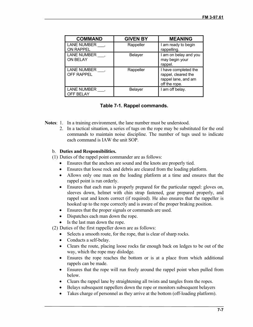
FM 3-97.61
7-7
COMMAND GIVEN BY MEANINGLANE NUMBER ___,ON RAPPEL
Rappeller I am ready to beginrappelling.
LANE NUMBER ___,ON BELAY
Belayer I am on belay and youmay begin yourrappel.
LANE NUMBER ___,OFF RAPPEL
Rappeller I have completed therappel, cleared therappel lane, and amoff the rope.
LANE NUMBER ___,OFF BELAY
Belayer I am off belay.
Table 7-1. Rappel commands.
Notes: 1. In a training environment, the lane number must be understood.2. In a tactical situation, a series of tugs on the rope may be substituted for the oral
commands to maintain noise discipline. The number of tugs used to indicateeach command is IAW the unit SOP.
b. Duties and Responsibilities. (1) Duties of the rappel point commander are as follows:
• Ensures that the anchors are sound and the knots are properly tied.• Ensures that loose rock and debris are cleared from the loading platform.• Allows only one man on the loading platform at a time and ensures that the
rappel point is run orderly.• Ensures that each man is properly prepared for the particular rappel: gloves on,
sleeves down, helmet with chin strap fastened, gear prepared properly, andrappel seat and knots correct (if required). He also ensures that the rappeller ishooked up to the rope correctly and is aware of the proper braking position.
• Ensures that the proper signals or commands are used.• Dispatches each man down the rope.• Is the last man down the rope.
(2) Duties of the first rappeller down are as follows:• Selects a smooth route, for the rope, that is clear of sharp rocks.• Conducts a self-belay.• Clears the route, placing loose rocks far enough back on ledges to be out of the
way, which the rope may dislodge. • Ensures the rope reaches the bottom or is at a place from which additional
rappels can be made.• Ensures that the rope will run freely around the rappel point when pulled from
below.• Clears the rappel lane by straightening all twists and tangles from the ropes.• Belays subsequent rappellers down the rope or monitors subsequent belayers• Takes charge of personnel as they arrive at the bottom (off-loading platform).

FM 3-97.61
7-8
Note: A rappeller is always belayed from the bottom, except for the first man down. Thefirst man belays himself down the rope using a self-belay attached to his rappel seat,which is hooked to the rappel rope with a friction knot. As the first man rappelsdown the rope, he “walks” the friction knot down with him.
(3) Each rappeller down clears the ropes, and shouts, “Off rappel,” (if the tacticalsituation permits). After the rope is cleared and the rappeller is off rappel, he acts as thebelayer for next rappeller.
(4) Soldiers wear gloves for all types of rappels to protect their hands from ropeburns.
(5) Rappellers descend in a smooth, controlled manner.(6) The body forms an L-shape with the feet shoulder-width apart, legs straight, and
buttocks parallel to the ground. When carrying equipment or additional weight, amodified L-shape is used with the legs slightly lower than the buttocks to compensate forthe additional weight. The rappeller’s back is straight. He looks over the brake shoulder.The guide hand is extended on the rope with the elbow extended and locked. The ropeslides freely through the guide hand. The guide hand is used to adjust equipment andassist balance during descent. The rappeller grasps the rope firmly with the brake handand places it in the brake position. Releasing tension on the rope and moving the brakehand regulates the rate of descent. The rappeller never lets go of the ropes with his brakehand until the rappel is complete.
c. Tying Off During the Rappel. It may be necessary to stop during descent. This canbe accomplished by passing the rope around the body and placing three or more wrapsaround the guide-hand-side leg, or by tying off using the appropriate knot for therappel device.
7-8. RECOVERY OF THE RAPPEL POINTAfter almost all personnel have descended, only two personnel will remain at the top ofthe rappel point. They will be responsible for establishing a retrievable rappel.
a. Establishing the Retrievable Rappel. To set up a retrievable rappel point, aclimber must apply one of the following methods:
(1) Double the rope when the rappel is less than half the total length of the rope. Placethe rope, with the bight formed by the midpoint, around the primary anchor. Join the tails ofthe rappel rope and throw the rope over the cliff. Tie a clove hitch around a carabiner, justbelow the anchor point, with the locking bar outside the carabiner away from the gateopening end and facing uphill. Snap the opposite standing portion into the carabiner. Whenthe rappeller reaches the bottom, he pulls on that portion of the rope to which the carabineris secured to allow the rope to slide around the anchor point.
(2) When the length of the rappel is greater than half the length of the rope used, jointwo ropes around the anchor point with an appropriate joining knot (except the squareknot). Adjust the joining knot so that it is away from the anchor. Tie a clove hitch arounda carabiner just below the anchor point with the locking bar outside the carabiner awayfrom the gate opening end and facing uphill. Snap the opposite standing portion into thecarabiner. Upon completion of the rappel, pull the rope to which the carabiner is securedto allow the rope to slide around the anchor point.

FM 3-97.61
7-9
Notes: 1. When setting up a retrievable rappel, use only a primary point; care is taken inselecting the point.
2. Ensure the soldiers have a safety line when approaching the rappel point, withonly the rappeller going near the edge.
b. Retrieving the Rappel Rope. The next to last rappeller will descend the lane,removing any twists, and routes the rope for easiest retrieval. Once he reaches the end of therappel, he tests the rope for retrieval. If the rappel is retrievable, the last man will rappeldown. Once he is off rappel, he pulls the lane down.
7-9. TYPES OF RAPPELSDuring military mountaineering operations, many types of rappels may be used. Thefollowing paragraphs describe some these rappels.
a. Hasty Rappel (Figure 7-4). The hasty rappel is used only on moderate pitches. Itsmain advantage is that it is easier and faster than other methods. Gloves are worn toprevent rope burns.
(1) Facing slightly sideways to the anchor, the rappeller places the ropes horizontallyacross his back. The hand nearest to the anchor is his guide hand, and the other is thebrake hand.
(2) To stop, the rappeller brings his brake hand across in front of his body locking therope. At the same time, he turns to face up toward the anchor point.
Figure 7-4. Hasty rappel.
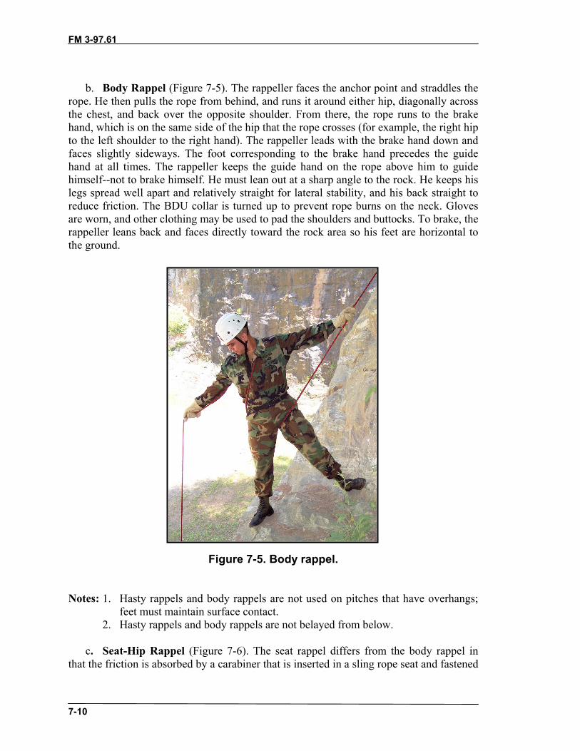
FM 3-97.61
7-10
b. Body Rappel (Figure 7-5). The rappeller faces the anchor point and straddles therope. He then pulls the rope from behind, and runs it around either hip, diagonally acrossthe chest, and back over the opposite shoulder. From there, the rope runs to the brakehand, which is on the same side of the hip that the rope crosses (for example, the right hipto the left shoulder to the right hand). The rappeller leads with the brake hand down andfaces slightly sideways. The foot corresponding to the brake hand precedes the guidehand at all times. The rappeller keeps the guide hand on the rope above him to guidehimself--not to brake himself. He must lean out at a sharp angle to the rock. He keeps hislegs spread well apart and relatively straight for lateral stability, and his back straight toreduce friction. The BDU collar is turned up to prevent rope burns on the neck. Glovesare worn, and other clothing may be used to pad the shoulders and buttocks. To brake, therappeller leans back and faces directly toward the rock area so his feet are horizontal tothe ground.
Figure 7-5. Body rappel.
Notes: 1. Hasty rappels and body rappels are not used on pitches that have overhangs;feet must maintain surface contact.
2. Hasty rappels and body rappels are not belayed from below.
c. Seat-Hip Rappel (Figure 7-6). The seat rappel differs from the body rappel inthat the friction is absorbed by a carabiner that is inserted in a sling rope seat and fastened

FM 3-97.61
7-11
to the rappeller. This method provides a faster and more frictional descent than othermethods. Gloves can be worn to prevent rope burns.
Figure 7-6. Seat-hip rappel.
(1) An alternate technique is to insert two carabiners opposite and opposed. Theninsert a locking carabiner into the two carabiners with opening gate on brake hand side.Then run the rope through the single carabiner. This helps to keep the rappel rope awayfrom the harness.
(2) To hook up for the seat-hip method, stand to one side of the rope. If using a right-hand brake, stand to the left of the rappel rope facing the anchor; if using a left-handbrake, stand to the right of the rappel rope. Place the rappel rope(s) into the lockingcarabiner; slack is taken between the locking carabiner and anchor point and wrappedaround the shaft of the locking carabiner and placed into the gate so that a round turn ismade around the shaft of the locking carabiner (Figure 7-7, page 7-12). Any remainingslack is pulled toward the uphill anchor point. If a single rope is used, repeat this processto place two round turns around the shaft of the locking carabiner. Face the anchor pointand descend using the upper hand as the guide and the lower hand as the brake. Thismethod has minimal friction, and is fast and safe. However, care is taken that the rope ishooked correctly into the carabiner to avoid the gate being opened by the rope. Looseclothing or equipment around the waist may be accidentally pulled into the lockingcarabiner and lock (stop) the rappel. For this reason, the rappeller must tuck in his shirtand keep his equipment out of the way during his descent.

FM 3-97.61
7-12
Figure 7-7. Proper hookup using carabiner wrap.
d. Figure-Eight Descender. The figure-eight descender puts less kinks in the rope,and it can be used with one or two ropes (Figure 7-8).
(1) To use the figure-eight descender, pass a bight through the large eye and thenover the small eye onto the neck. Place the small eye into a locking carabiner. To reducethe amount of friction on the figure-eight, place the original bight into the carabiner andnot around the neck of the descender. (Less friction requires more braking force from therappeller.)
(2) The guide hand goes on the rope that is running from the anchor. The brake handgoes on the slack rope. The brake is applied by moving the brake hand to the rear ordownward.

FM 3-97.61
7-13
Figure 7-8. Figure-eight descender.
d. Other Devices. Many different types of devices are similar in design andoperation to the basic plate. These include slots or plates and tubers. Most of thesedevices can accommodate two ropes not greater than 7/16 of an inch in size. Followmanufacturer’s directions for using these devices for rappelling.
e. Extending the Rappel Device. The rappel device can be extended using either apiece of webbing or cordage to move the device away from the body and the harness,preventing accidental damage (Figure 7-9, page 7-14). It also allows for easier self-belay.
f. Self-Belay Techniques. A friction knot can be used as a belay for a rappeller(Figure 7-9, page 7-14). The knot acts as the brake hand when the rappeller must work ornegotiate an obstacle requiring the use of both hands. The knot acts as a belay if therappeller loses control of the rope.

FM 3-97.61
7-14
Figure 7-9. Extended hookup with self-belay.
Section III. ONE-ROPE BRIDGEThe one-rope bridge is constructed using a static rope. The rope is anchored with ananchor knot on the far side of the obstacle and is tied off at the near end with a tighteningsystem. A one-rope bridge may be built many ways, depending upon the tactical situationand area to be crossed (crossing a gorge above the tree line may require constructingartificial anchors). However, they all share common elements to safely construct and usethe bridge: two suitable anchors; good loading and unloading platforms; a rope about1-meter (waist) high for loading and unloading; a tightening system; and a rope tightenough for ease of crossing. Which side the tightening system is utilized, or whether ananchor knot or retrievable bowline is used, depends on the technique.

FM 3-97.61
7-15
7-10. SITE SELECTIONA suitable crossing site must have “bombproof” anchors on both the near side and far side.These anchors must be extremely strong due to the amount of tension that will be placedupon them. Natural anchors, such as large trees and solid rock formations, are alwayspreferred. The site must also have suitable loading and off-loading platforms to facilitatesafe personnel movement.
7-11. INSTALLATION USING TRANSPORT TIGHTENING SYSTEMThe transport tightening system provides a mechanical advantage without requiringadditional equipment.
a. The rope must first be anchored on the far side of the obstacle. If crossing astream, the swimmer must be belayed across. If crossing a ravine or gorge, crossing mayinvolve rappelling and a roped climb. Once across, the swimmer/climber will temporarilyanchor the installation rope.
b. One man on the near side ties a fixed-loop knot (for example, wireman’s,figure-eight slip knot) approximately 3 feet from the near side anchor and places thecarabiner into the loop of the knot. The opening gate must be up and away from the loop.If two carabiners are used, the gates will be opposing. At that time, soldiers route theremainder of the rope around the near side anchor point and hook the rope into thecarabiner. This system is known as a transport-tightening system (Figure 7-10). The manon the far side pulls the knot out four to six feet from the near anchor.
c. Once the knot has been pulled out, the far side man anchors the rope using atensionless anchor. The anchor should be waist high.
Figure 7-10. Transport tightening system.

FM 3-97.61
7-16
d. A three-man pull team on the near side pulls the slack out of the installation rope.The knot should be close enough to the near side anchor to allow personnel to easily loadthe installation.
Note: No more than three personnel should be used to tighten the rope. Using morepersonnel can over-tighten the rope and bring the rope critically close to failure.
e. The rope the can be secured using one of three methods: transport knot (Figure7-11), round turn around anchor and two half hitches on a bight (Figure 7-12), or atensionless anchor knot (Figure 7-13).
Figure 7-11. Transport knot.

FM 3-97.61
7-17
Figure 7-12. Round turn around anchor and two half hitches on a bight.
Figure 7-13. Tensionless anchor knot.
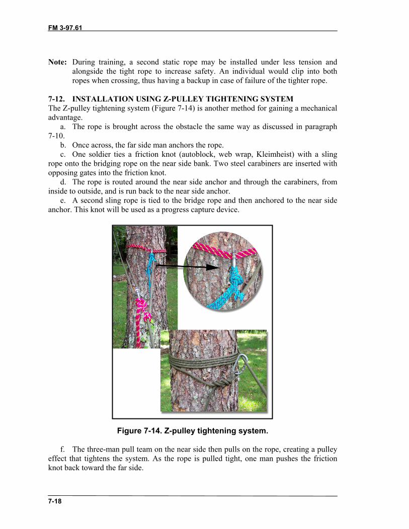
FM 3-97.61
7-18
Note: During training, a second static rope may be installed under less tension andalongside the tight rope to increase safety. An individual would clip into bothropes when crossing, thus having a backup in case of failure of the tighter rope.
7-12. INSTALLATION USING Z-PULLEY TIGHTENING SYSTEMThe Z-pulley tightening system (Figure 7-14) is another method for gaining a mechanicaladvantage.
a. The rope is brought across the obstacle the same way as discussed in paragraph7-10.
b. Once across, the far side man anchors the rope.c. One soldier ties a friction knot (autoblock, web wrap, Kleimheist) with a sling
rope onto the bridging rope on the near side bank. Two steel carabiners are inserted withopposing gates into the friction knot.
d. The rope is routed around the near side anchor and through the carabiners, frominside to outside, and is run back to the near side anchor.
e. A second sling rope is tied to the bridge rope and then anchored to the near sideanchor. This knot will be used as a progress capture device.
Figure 7-14. Z-pulley tightening system.
f. The three-man pull team on the near side then pulls on the rope, creating a pulleyeffect that tightens the system. As the rope is pulled tight, one man pushes the frictionknot back toward the far side.

FM 3-97.61
7-19
g. When the rope is tight, it is tied off with a tensionless anchor knot, transport knot,or round turn around anchor and two half hitches on a bight.
7-13. UTILIZATIONThe rope bridge can be used to move personnel and equipment over obstacles. There areseveral methods of accomplishing this.
a. Method of Crossing. If dry crossing is impossible, soldiers will use the ropebridge as a hand line. Preferably, all soldiers will tie a safety line and attach it to the ropeinstallation as they cross. If the soldier must cross with his rucksack, he may wear it overboth shoulders, although the preferred method is to place another carabiner into the top ofthe rucksack frame, attach it to the bridge, and pull the rucksack across. Soldiers willalways cross on the downstream side of the installation. If a dry crossing is possiblesoldiers will use one of three methods: commando crawl, monkey crawl, and Tyroleantraverse.
(1) Commando Crawl (Figure 7-15). The soldier lies on top of the rope with theupstream foot hooked on the rope and the knee bent close to the buttocks; thedownstream leg hangs straight to maintain balance. He progresses by pulling with hishands and arms. To recover if he falls over, the soldier hooks one leg and the oppositearm over the rope, and then pushes down with the other hand to regain position.
Figure 7-15. Commando crawl.
Note: Only one man at a time is allowed on the bridge while conducting a commandocrawl.
(2) Monkey Crawl (Figure 7-16, page 7-20). The soldier hangs below the ropesuspended by his hands with both heels crossed over the rope. He pulls with his handsand arms, and pushes with his feet to make progress.

FM 3-97.61
7-20
Figure 7-16. Monkey crawl.
(3) Rappel Seat Method (Figure 7-17). The soldier ties a rappel seat (or dons a seatharness) with the carabiner facing up and away from his body. He then faces the rope andclips into the rope bridge. He rotates under the rope and pulls with his hands and arms tomake progress. The rappel seat method is the preferred method. If crossing withrucksacks, a carabiner is inserted into the frame and attached to the rope bridge. Thesoldier the places one or both legs through the shoulder carrying straps and pulls therucksack across.
Figure 7-17. Rappel seat method.

FM 3-97.61
7-21
b. Rigging Special Equipment. Any special equipment, such as crew-servedweapons, ammunition, or supplies, must be rigged for movement across the rope bridge.A unit SOP may dictate the rigging of these items, but many expedient methods exist.The rigging should use various items that would be readily available to a deployed unit.Some of these items include tubular nylon webbing, cordage (various sizes), andcarabiners.
(1) Machine Guns. To rig machine guns, use a sling rope and tie a rerouted figure-eight around the spine of the front sight post. Then tie two evenly spaced fixed loops.Finally, anchor the sling rope to the buttstock of the machine gun. Additional tie downsmay be necessary to prevent accidental disassembly of the weapon.
(2) ALICE Packs. ALICE packs can be joined together with a sling to facilitatemoving more than one rucksack at one time.
7-14. HAULING LINEA hauling line may be used to move rucksacks or casualties across the rope bridge(Figure 7-18).
a. Construction. An additional rope is brought across the rope bridge and anchoredto the far side. The other end is anchored on the near side. All the slack is pulled to thenear side, and a figure-eight slip knot is tied at the loading platform. A carabiner isinserted into the loop and clipped onto the rope bridge.
Figure 7-18. Hauling line.
b. Moving Rucksacks. Use carabiners to attach the rucksack frames to the ropebridge. Then clip the carabiner of the hauling line into the carabiner of the rucksackclosest to the far side. Personnel on the far side pull the rucksacks across using thehauling line while personnel on the near side manages the slack at all times.
c. Moving Litters. The carabiner of the hauling line will remain on the rope bridge.On each side of this carabiner, using the hauling line tie a middle-of-the-rope clove hitcharound both of the horizontal lift straps of the litter. Remove the slack between thecarabiners. Then place the carabiners in each of the lift straps onto the rope bridge. Thesame technique used for the rucksacks is used to pull the litter across.
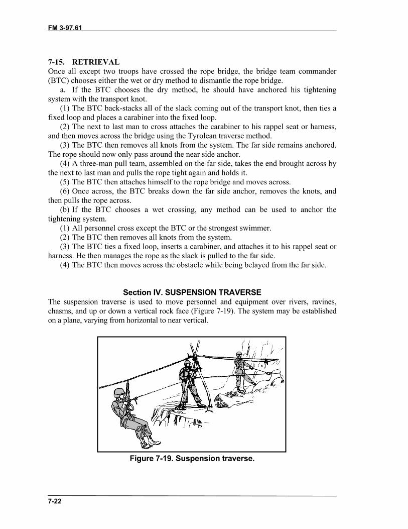
FM 3-97.61
7-22
7-15. RETRIEVALOnce all except two troops have crossed the rope bridge, the bridge team commander(BTC) chooses either the wet or dry method to dismantle the rope bridge.
a. If the BTC chooses the dry method, he should have anchored his tighteningsystem with the transport knot.
(1) The BTC back-stacks all of the slack coming out of the transport knot, then ties afixed loop and places a carabiner into the fixed loop.
(2) The next to last man to cross attaches the carabiner to his rappel seat or harness,and then moves across the bridge using the Tyrolean traverse method.
(3) The BTC then removes all knots from the system. The far side remains anchored.The rope should now only pass around the near side anchor.
(4) A three-man pull team, assembled on the far side, takes the end brought across bythe next to last man and pulls the rope tight again and holds it.
(5) The BTC then attaches himself to the rope bridge and moves across.(6) Once across, the BTC breaks down the far side anchor, removes the knots, and
then pulls the rope across.(b) If the BTC chooses a wet crossing, any method can be used to anchor the
tightening system.(1) All personnel cross except the BTC or the strongest swimmer.(2) The BTC then removes all knots from the system.(3) The BTC ties a fixed loop, inserts a carabiner, and attaches it to his rappel seat or
harness. He then manages the rope as the slack is pulled to the far side.(4) The BTC then moves across the obstacle while being belayed from the far side.
Section IV. SUSPENSION TRAVERSEThe suspension traverse is used to move personnel and equipment over rivers, ravines,chasms, and up or down a vertical rock face (Figure 7-19). The system may be establishedon a plane, varying from horizontal to near vertical.
Figure 7-19. Suspension traverse.
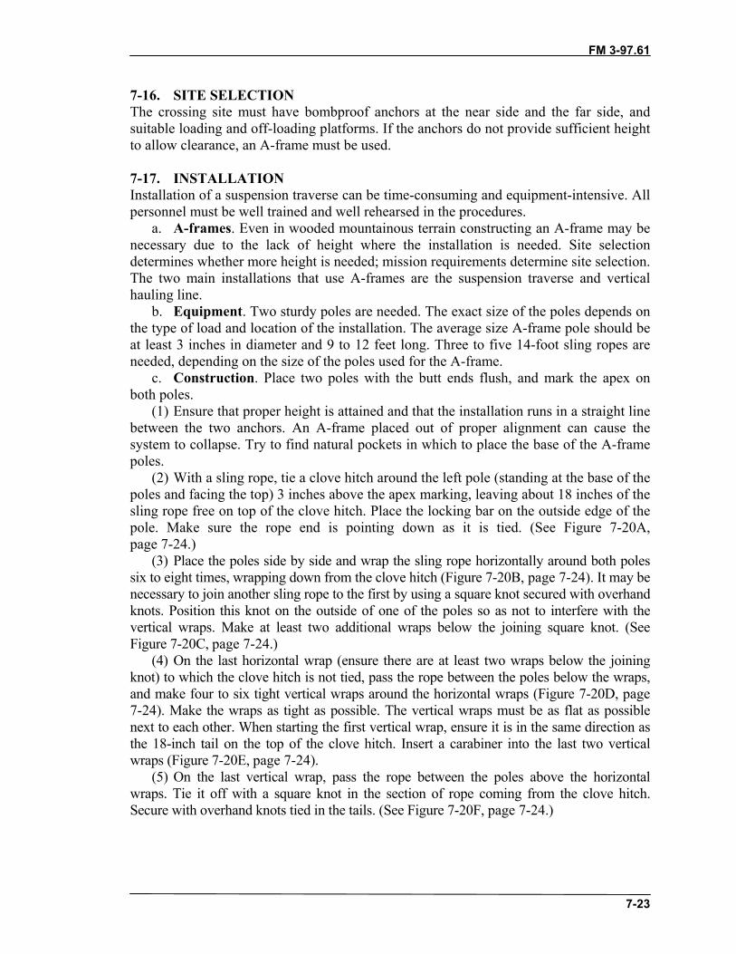
FM 3-97.61
7-23
7-16. SITE SELECTIONThe crossing site must have bombproof anchors at the near side and the far side, andsuitable loading and off-loading platforms. If the anchors do not provide sufficient heightto allow clearance, an A-frame must be used.
7-17. INSTALLATIONInstallation of a suspension traverse can be time-consuming and equipment-intensive. Allpersonnel must be well trained and well rehearsed in the procedures.
a. A-frames. Even in wooded mountainous terrain constructing an A-frame may benecessary due to the lack of height where the installation is needed. Site selectiondetermines whether more height is needed; mission requirements determine site selection.The two main installations that use A-frames are the suspension traverse and verticalhauling line.
b. Equipment. Two sturdy poles are needed. The exact size of the poles depends onthe type of load and location of the installation. The average size A-frame pole should beat least 3 inches in diameter and 9 to 12 feet long. Three to five 14-foot sling ropes areneeded, depending on the size of the poles used for the A-frame.
c. Construction. Place two poles with the butt ends flush, and mark the apex onboth poles.
(1) Ensure that proper height is attained and that the installation runs in a straight linebetween the two anchors. An A-frame placed out of proper alignment can cause thesystem to collapse. Try to find natural pockets in which to place the base of the A-framepoles.
(2) With a sling rope, tie a clove hitch around the left pole (standing at the base of thepoles and facing the top) 3 inches above the apex marking, leaving about 18 inches of thesling rope free on top of the clove hitch. Place the locking bar on the outside edge of thepole. Make sure the rope end is pointing down as it is tied. (See Figure 7-20A,page 7-24.)
(3) Place the poles side by side and wrap the sling rope horizontally around both polessix to eight times, wrapping down from the clove hitch (Figure 7-20B, page 7-24). It may benecessary to join another sling rope to the first by using a square knot secured with overhandknots. Position this knot on the outside of one of the poles so as not to interfere with thevertical wraps. Make at least two additional wraps below the joining square knot. (SeeFigure 7-20C, page 7-24.)
(4) On the last horizontal wrap (ensure there are at least two wraps below the joiningknot) to which the clove hitch is not tied, pass the rope between the poles below the wraps,and make four to six tight vertical wraps around the horizontal wraps (Figure 7-20D, page7-24). Make the wraps as tight as possible. The vertical wraps must be as flat as possiblenext to each other. When starting the first vertical wrap, ensure it is in the same direction asthe 18-inch tail on the top of the clove hitch. Insert a carabiner into the last two verticalwraps (Figure 7-20E, page 7-24).
(5) On the last vertical wrap, pass the rope between the poles above the horizontalwraps. Tie it off with a square knot in the section of rope coming from the clove hitch.Secure with overhand knots tied in the tails. (See Figure 7-20F, page 7-24.)

FM 3-97.61
7-24
Figure 7-20. A-frame horizontal and vertical wraps.
(6) Use a spreader rope to prevent the A-frame from collapsing from pressure applied atthe apex (Figure 7-21). If the ground is soft, dig the legs in about 6 inches. Tie a sling ropebetween the legs with a round turn with two half hitches around each leg. Remove all slackin the rope between the legs.
(7) If the ground is a hard surface, tie end-of-the-rope clove hitches with the lockingportions facing to the rear, the direction of kick. Tie the tails off at a 45-degree angle witha round turn and two half hitches to a secondary anchor point. The spreader rope shouldbe no more than 6 inches above ground level. The use of clove hitches and half hitchespermits easy adjustment of the spreader rope. If more than one sling rope is needed, tiethe two ropes together with a square knot and secure with half hitches or overhand knots.
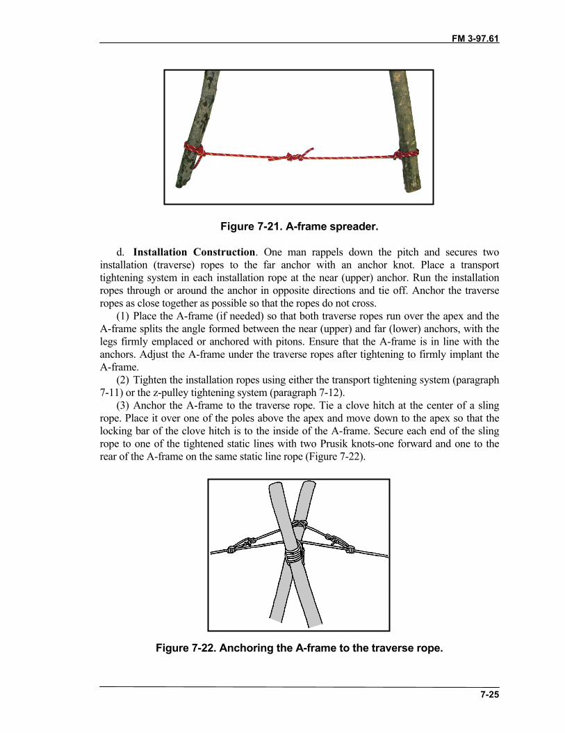
FM 3-97.61
7-25
Figure 7-21. A-frame spreader.
d. Installation Construction. One man rappels down the pitch and secures twoinstallation (traverse) ropes to the far anchor with an anchor knot. Place a transporttightening system in each installation rope at the near (upper) anchor. Run the installationropes through or around the anchor in opposite directions and tie off. Anchor the traverseropes as close together as possible so that the ropes do not cross.
(1) Place the A-frame (if needed) so that both traverse ropes run over the apex and theA-frame splits the angle formed between the near (upper) and far (lower) anchors, with thelegs firmly emplaced or anchored with pitons. Ensure that the A-frame is in line with theanchors. Adjust the A-frame under the traverse ropes after tightening to firmly implant theA-frame.
(2) Tighten the installation ropes using either the transport tightening system (paragraph7-11) or the z-pulley tightening system (paragraph 7-12).
(3) Anchor the A-frame to the traverse rope. Tie a clove hitch at the center of a slingrope. Place it over one of the poles above the apex and move down to the apex so that thelocking bar of the clove hitch is to the inside of the A-frame. Secure each end of the slingrope to one of the tightened static lines with two Prusik knots-one forward and one to therear of the A-frame on the same static line rope (Figure 7-22).
Figure 7-22. Anchoring the A-frame to the traverse rope.
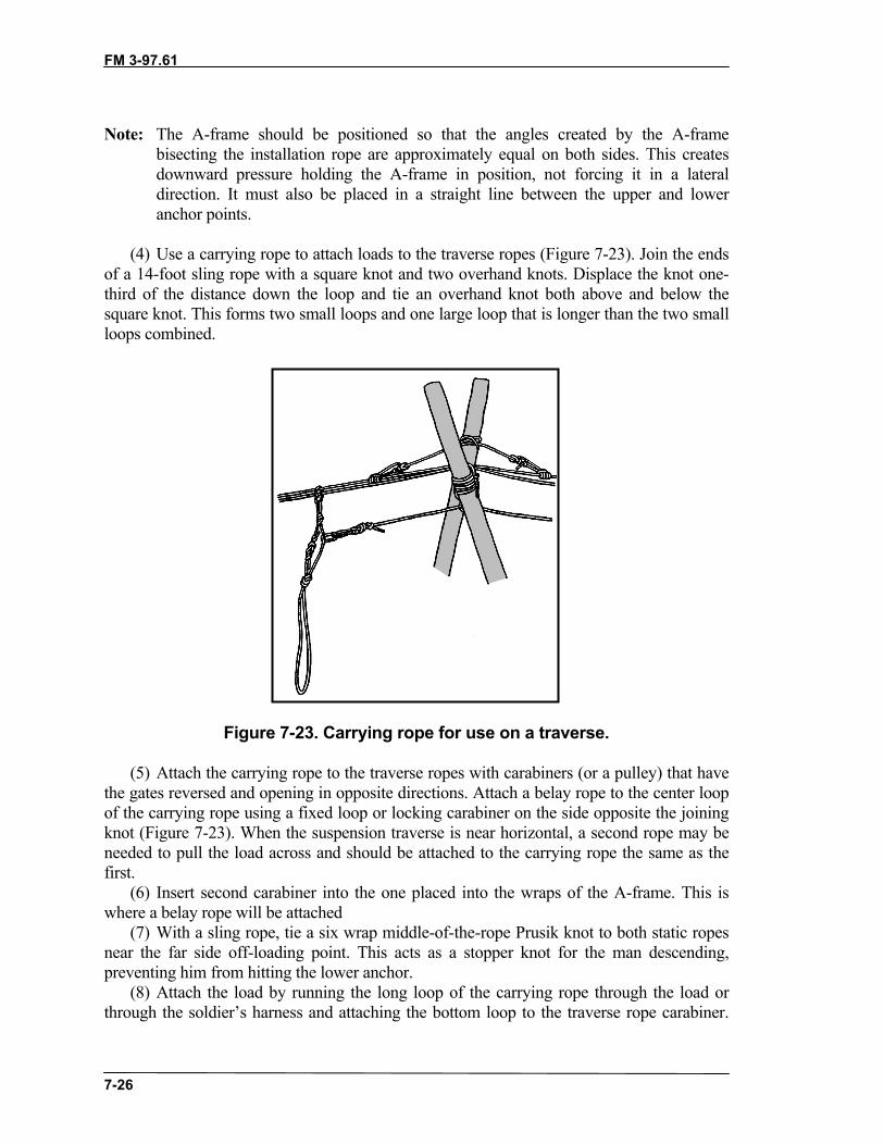
FM 3-97.61
7-26
Note: The A-frame should be positioned so that the angles created by the A-framebisecting the installation rope are approximately equal on both sides. This createsdownward pressure holding the A-frame in position, not forcing it in a lateraldirection. It must also be placed in a straight line between the upper and loweranchor points.
(4) Use a carrying rope to attach loads to the traverse ropes (Figure 7-23). Join the endsof a 14-foot sling rope with a square knot and two overhand knots. Displace the knot one-third of the distance down the loop and tie an overhand knot both above and below thesquare knot. This forms two small loops and one large loop that is longer than the two smallloops combined.
Figure 7-23. Carrying rope for use on a traverse.
(5) Attach the carrying rope to the traverse ropes with carabiners (or a pulley) that havethe gates reversed and opening in opposite directions. Attach a belay rope to the center loopof the carrying rope using a fixed loop or locking carabiner on the side opposite the joiningknot (Figure 7-23). When the suspension traverse is near horizontal, a second rope may beneeded to pull the load across and should be attached to the carrying rope the same as thefirst.
(6) Insert second carabiner into the one placed into the wraps of the A-frame. This iswhere a belay rope will be attached
(7) With a sling rope, tie a six wrap middle-of-the-rope Prusik knot to both static ropesnear the far side off-loading point. This acts as a stopper knot for the man descending,preventing him from hitting the lower anchor.
(8) Attach the load by running the long loop of the carrying rope through the load orthrough the soldier’s harness and attaching the bottom loop to the traverse rope carabiner.

FM 3-97.61
7-27
Descent must be belayed slowly and be controlled. Soldiers descending should hold onto thecarrying rope and keep their feet high to avoid contact with the ground. Due to the constanttension maintained on the belayer, use a mechanical belay. If the belayer cannot view theentire descent route, use a relay man.
7-18. RETRIEVALThe suspension traverse is not as readily retrievable as the one-rope bridge. Therefore, theinstalling unit should dismantle it after it is no longer needed.
Section V. VERTICAL HAULING LINEThe vertical hauling line is an installation used to move men and equipment up vertical ornear-vertical slopes (Figure 7-24). It is often used with a fixed rope for personnel movement.The hauling line is used to move equipment, such as mortars or other crew-served weapons,rucksacks, or supplies
Figure 7-24. Vertical hauling line.
7-19. SITE SELECTIONThe first and most important task is to determine where to construct the vertical hauling line.The site must have an appropriate top anchor that is secure enough to hold the system andload. Loading and unloading platforms should be easily accessible natural platforms thatprovide a safe working area. The ideal platform at the top allows construction of the verticalhauling line without the use of an A-frame. The site should also have sufficient clearance toallow for space between the slope and pulley rope for easy hauling of troops or equipment.

FM 3-97.61
7-28
7-20. INSTALLATIONConstruct an A-frame, if necessary, and anchor it. Double one installation rope, find themiddle, and lay the middle of the installation rope over the apex of the A-frame; a30-centimeter (12-inch) bight should hang below the apex.
a. To maintain the 12-inch bight, tie clove hitches above the A-frame lashing oneach side of the apex with the installation rope, ensuring that the locking bars of the clovehitches are on the inside. Ensure that the portion of the rope that forms the bight comesout of the bottom of the clove hitch. (See Figure 7-25.)
Figure 7-25. Attaching the anchor rope to the A-frame.
b. To anchor the A-frame, use a transport tightening system with the doubled rope,which is tied to the A-frame. Tie this off at an anchor point to the rear of the A-frameinstallation and adjust the angle of the A-frame so it leans out over the cliff edge. Theangle should be 15 to 25 degrees unloaded. The A-frame should not lean outward morethan 45 degrees once loaded since the legs can lose their position.
c. Tie the ends of another installation rope together with a joining knot to form thehauling line. Attach the rope to the system by two carabiners with gates up and opposedor one mountain rescue pulley with a locking steel carabiner in the 12-inch bight hangingfrom the apex of the A-frame. Tie fixed loops (wireman’s, directional figure-eight, orsingle butterfly) on opposite sides of the endless rope at the loading and unloadingplatforms.
d. Attach equipment to the hauling line 12 inches above the joining knot by acarabiner in the fixed loop.
FM 3-97.61
7-29
e. Additional fixed loops may be tied in the hauling line for more control over theobject when moving large loads. Attach personnel to the hauling line by use of a rappelseat or seat harness.
Note: Mortar tubes and similar objects are attached to the line by two knots so that the tubestays parallel and as close to the hauling line as possible.
f. When personnel are moved using a vertical hauling line, make a knotted hand line;anchor it in line with, or to, the primary anchor (round turn with a bowline); and place itover the spreader on the legs of the A-frame. Space the overhand knots in the knotted handline 12 inches apart, with about 20 feet of rope without knots at one end for the anchor.Throw the knotted hand line over the A-frame spreader rope and down the side of the cliff.Personnel ascending the vertical hauling line use this as a simple fixed rope.
g. Use as many men as needed to pull the load to the top by pulling on the ropeopposite the load. If equipment and personnel are only being lowered, belay from the topusing the hauling line. Station two climbers at the unloading platform to retrieve loads.
h. If only equipment is being hauled up, it is not necessary to use the knotted hand linerope, but it may be necessary to use a belay rope. To move materials or troops up on oneside of the hauling line, pull the other side from below.
Note: Personnel using the hauling line for movement must apply all related principles ofclimbing. Always station two operators at the top of the vertical hauling line to aidmen or to retrieve loads when they reach the top. They will always be safetied whileworking near the edge. When in use, the A-frame should lean slightly over the edgeof the cliff to prevent excessive wear on the ropes that pass over sharp rocks. Reduceexcessive friction on the system. Remove all obstacles and any loose objects thatcould be dislodged by personnel and equipment.
7-21. RETRIEVALThe vertical hauling line is used along a main supply route. When it is no longer needed, theinstalling unit will return and dismantle the system.
Section VI. SIMPLE RAISING SYSTEMSMoving heavy objects with limited manpower may be necessary in mountainous terrain. Toreduce fatigue of those personnel moving the load, simple rigging techniques can be used toincrease the mechanical advantage of the hauling system.
7-22. Z-PULLEY SYSTEMThe Z-pulley system is a simple, easily constructed hauling system (Figure 7-26, page 7-30).
a. Considerations. Anchors must be sturdy and able to support the weight of the load.Site selection is governed by different factors: tactical situation, weather, terrain, equipment,load weight, and availability of anchors.
b. Theory. Use carabiners as a substitute if pulleys are not available. The mechanicaladvantage obtained in theory is 3:1. The less friction involved the greater the mechanical
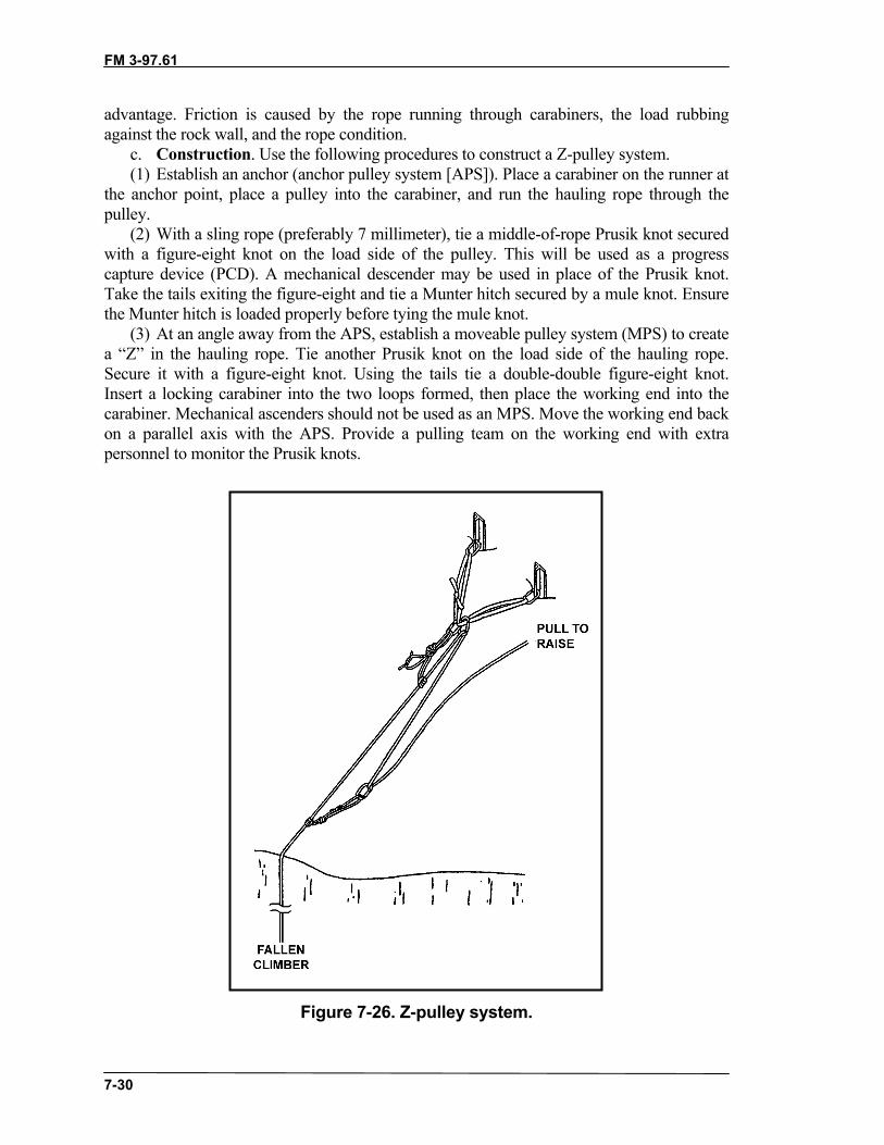
FM 3-97.61
7-30
advantage. Friction is caused by the rope running through carabiners, the load rubbingagainst the rock wall, and the rope condition.
c. Construction. Use the following procedures to construct a Z-pulley system.(1) Establish an anchor (anchor pulley system [APS]). Place a carabiner on the runner at
the anchor point, place a pulley into the carabiner, and run the hauling rope through thepulley.
(2) With a sling rope (preferably 7 millimeter), tie a middle-of-rope Prusik knot securedwith a figure-eight knot on the load side of the pulley. This will be used as a progresscapture device (PCD). A mechanical descender may be used in place of the Prusik knot.Take the tails exiting the figure-eight and tie a Munter hitch secured by a mule knot. Ensurethe Munter hitch is loaded properly before tying the mule knot.
(3) At an angle away from the APS, establish a moveable pulley system (MPS) to createa “Z” in the hauling rope. Tie another Prusik knot on the load side of the hauling rope.Secure it with a figure-eight knot. Using the tails tie a double-double figure-eight knot.Insert a locking carabiner into the two loops formed, then place the working end into thecarabiner. Mechanical ascenders should not be used as an MPS. Move the working end backon a parallel axis with the APS. Provide a pulling team on the working end with extrapersonnel to monitor the Prusik knots.
Figure 7-26. Z-pulley system.

FM 3-97.61
7-31
d. Other Factors. If the two pulleys touch, the “Z” is lost along with the mechanicaladvantage. For greater efficiency, the main anchor should be well back from the edge and allropes should pull parallel to the load.
Note: Avoid the possibility of overstressing the anchors. Be aware of reduced sensitivity tothe load due to the mechanical advantage. Use belays and backup safeties. Protectthe rope from edges and other abrasive parts of the rock.
7-23. U-PULLEY SYSTEMThe U-pulley system is another simple, easily-constructed hauling system (Figure 7-27,page 7-32).
a. Considerations. Anchors must be sturdy and able to support the weight of the load.Site selection is governed by different factors: tactical situation, weather, terrain, equipment,load weight, and availability of anchors.
b. Theory. Use carabiners as a substitute if pulleys are not available. The mechanicaladvantage obtained in theory is 2:1. The less friction involved the greater the mechanicaladvantage. Friction is caused by the rope running through carabiners, the load rubbingagainst the rock wall, and the rope condition.
c. Construction. Use the following procedures construct a U-pulley system.(1) Anchor the hauling rope.(2) Prepare the load or casualty for hauling. Place a locking carabiner the on to the
harness or the rigged load. (3) Lower a bight to the casualty or the load.(4) Place the bight into the carabiner; or place the bight on to a pulley and then place
pulley into the carabiner.(5) Construct a second anchor. Attach a locking carabiner to the anchor.(6) Tie a middle of the rope Prusik onto the haul rope exiting the pulley. Secure the
Prusik with a double-double figure eight. This is the PCD. Place the fixed loops intothe locking carabiner of the second anchor.

FM 3-97.61
7-32
Figure 7-27. U-pulley system.
FM 3-97.61(TC 90-6-1)
8-1
CHAPTER 8MOUNTAIN WALKING TECHNIQUES
Mountain travel encompasses the full spectrum of techniques used tonegotiate steep, rugged terrain. Mountain walking on rock and snow,technical rock and ice climbing, skiing or snow shoeing, rappelling, andstream crossing are the key travel skills a military mountaineer mustpossess.
8-1. BASIC PRINCIPLESUp scree or talus, through boulder fields or steep wooded mountainsides, over snow orgrass-covered slopes, the basic principles of mountain walking remain the same.
a. The soldier’s weight is centered directly over the feet at all times. He places hisfoot flat on the ground to obtain as much (boot) sole-ground contact as possible. Then, heplaces his foot on the uphill side of grass tussocks, small talus and other level spots toavoid twisting the ankle and straining the Achilles tendon. He straightens the knee aftereach step to allow for rest between steps, and takes moderate steps at a steady pace. Anangle of ascent or descent that is too steep is avoided, and any indentations in the slopeare used to advantage.
b. In addition to proper technique, pace is adapted to conditions. The mountaineersets a tempo, or number of steps per minute, according to the pace of the unit in which heis moving. (Physical differences mean that the tempos of two people moving at the samespeed will not always be the same.) The soldier maintains tempo and compensates forchanges of slope or terrain by adjusting the length of his stride. Tempo, pace, and rhythmare enhanced when an interval of three to five paces is kept between individuals. Thisinterval helps lessen the “accordion” effect of people at the end of the file who mustconstantly stop and start.
c. The terrain, weather, and light conditions affect the rate of climb. The moreadverse the conditions, the slower the pace. Moving too fast, even under ideal conditions,produces early fatigue, requires more rest halts, and results in loss of climbing time. Asoldier can only move as fast as his lungs and legs will allow. The trained, conditionedand acclimatized soldier has greater endurance and moves more efficiently. Rest, goodnutrition and hydration, conditioning, acclimatization, proper training, and the will toclimb are key to successful mountain operations.
d. Breaks are kept to a minimum. When a moderate pace is set, the need for resthalts decreases, the chance of personnel overheating is lessened, and a unit can cover agiven distance in a minimal time. If possible, rests should be taken on level groundavoiding steeper inclines.
(1) During the first half-hour of movement an adjustment halt should be taken.Soldiers will loosen or tighten bootlaces as needed, adjust packs and add or removeappropriate layers of clothing.
(2) Following the first halt, a well-conditioned party may take a short rest every 1 to1.5 hours. If possible, soldiers lean against a tree, rock, or hillside to relieve the shouldersof pack weight, breathe deeply, hydrate, and snack on trail food. These halts are keptshort enough to avoid muscles stiffening (one to two minutes).

FM 3-97.61
8-2
(3) Later in the march longer halts may be necessary due to fatigue or missionrequirements. At these halts soldiers should immediately put on additional clothing toavoid chilling—it is much easier to keep a warm body warm than to warm up a cold one.
(4) After a climb, a good rest is needed to revive tired muscles.e. The rest step is used for steep slopes, snowfields, and higher elevations. It
controls pace and limits fatigue by giving the lungs and legs a moment to recuperatebetween steps. Pace is kept slow and rhythmic.
(1) After each step forward, the soldier pauses briefly, relaxing the muscles of theforward leg while resting his entire bodyweight on the rear leg. The rear leg is keptstraight with the knee locked so that bone, not muscle, supports the weight.
(2) Breathing is synchronized with the rest step. The number of breaths per step willchange depending on the difficulty of the climb. Steeper slopes or higher elevations mayrequire several breaths per step. When the air thins at altitude it is especially important tobreathe deeply, using the “pressure breathing” technique. The soldier exhales strongly,enabling an easier, deeper inhale.
(3) This slow, steady, halting rest step is more efficient than spurts of speed, whichare rapidly exhausting and require longer recovery.
f. Downhill walking uses less energy than uphill but is much harder on the body.Stepping down can hammer the full bodyweight onto the feet and legs. Blisters andblackened toenails, knee damage, and back pain may follow. To avoid these problems thesoldier should start by tightening bootlaces to ensure a snug fit (also keep toenailstrimmed). A ski pole, ice ax, or walking stick will help take some of the load and giveadditional stability. (Refer to Chapter 11 for techniques and use of the ice ax.) Keep amoderate pace and walk with knees flexed to absorb shock.
g. Side hill travel on any surface should be avoided whenever possible. Weighteddown with a rucksack, the soldier is vulnerable to twisted ankles, back injury, and loss ofbalance. If side hill travel is necessary, try to switchback periodically, and use any lowerangle flat areas such as rocks, animal trails, and the ground above grass or brush clumpsto level off the route.
8-2. TECHNIQUESMountain walking techniques can be divided according to the general formation, surface,and ground cover such as walking on hard ground, on snow slopes and grassy slopes,through thick brush, and on scree and talus slopes.
a. Hard Ground. Hard ground is firmly compacted, rocky soil that does not giveway under the weight of a soldier’s step. It is most commonly found under mature forestcanopy, in low brush or heather, and areas where animals have beaten out multiple trails.
(1) When ascending, employ the rest step to rest the leg muscles. Steep slopes can betraversed rather than climbed straight up. To turn at the end of each traverse, the soldiershould step off in the new direction with the uphill foot. This prevents crossing the feetand possible loss of balance. While traversing, the full sole-to-ground principle isaccomplished by rolling the ankle downhill on each step. For small stretches theherringbone step may be used—ascending straight up a slope with toes pointed out. Anormal progression, as the slope steepens, would be from walking straight up, to aherringbone step, and then to a traverse on the steeper areas.

FM 3-97.61
8-3
(2) Descending is best done by walking straight down the slope without traversing.The soldier keeps his back straight and bends at the knees to absorb the shock of eachstep. Body weight is kept directly over the feet and the full boot sole is placed on theground with each step. Walking with a slight forward lean and with the feet in a normalposition make the descent easier.
b. Snow Slopes. Snow-covered terrain can be encountered throughout the yearabove 1,500 meters in many mountainous areas. Talus and brush may be covered byhardened snowfields, streams made crossable with snowbridges. The techniques forascending and descending moderate snow slopes are similar to walking on hard groundwith some exceptions.
(1) Diagonal Traverse Technique. The diagonal traverse is the most efficient meansto ascend snow. In conjunction with the ice ax it provides balance and safety for thesoldier. This technique is a two-step sequence. The soldier performs a basic rest step,placing the leading (uphill) foot above and in front of the trailing (downhill) foot, andweighting the trail leg. This is the in-balance position. The ice ax, held in the uphill hand,is placed in the snow above and to the front. The soldier shifts his weight to the leading(uphill) leg and brings the unweighted trail (downhill) foot ahead of the uphill foot. Heshifts weight to the forward (downhill) leg and then moves the uphill foot up and places itout ahead of the trail foot, returning to the in-balance position. At this point the ax ismoved forward in preparation for the next step.
(2) Step Kicking. Step kicking is a basic technique used when crampons are notworn. It is best used on moderate slopes when the snow is soft enough to leave clearfootprints. On softer snow the soldier swings his foot into the snow, allowing the leg’sweight and momentum to carve the step. Fully laden soldiers will need to kick steps,which take half of the boot. The steps should be angled slightly into the slope for addedsecurity. Succeeding climbers will follow directly in the steps of the trailbreaker, eachone improving the step as he ascends. Harder snow requires more effort to kick steps, andthey will not be as secure. The soldier may need to slice the step with the side of his bootand use the diagonal technique to ascend.
(3) Descending Snow. If the snow is soft and the slope gentle, simply walk straightdown. Harder snow or steeper slopes call for the plunge step, which must be done in apositive, aggressive manner. The soldier faces out, steps off, and plants his foot solidly,driving the heel into the snow while keeping his leg straight. He shifts his weight to thenew foot plant and continues down with the other foot. On steeper terrain it may benecessary to squat on the weighted leg when setting the plunge step. The upper bodyshould be kept erect or canted slightly forward.
(4) Tips on Snow Travel. The following are tips for travelling on snow.(a) Often the best descent is on a different route than the ascent. When looking for a
firmer travel surface, watch for dirty snow—this absorbs more heat and thus hardensfaster than clean snow.
(b) In the Northern Hemisphere, slopes with southern and western exposures set upearlier in the season and quicker after storms, but are more prone to avalanches in thespring. These slopes generally provide firm surfaces while northern and easternexposures remain unconsolidated.
(c) Travel late at night or early in the morning is best if daytime temperatures areabove freezing and the sun heats the slopes. The night’s cold hardens the snow surface.

FM 3-97.61
8-4
(d) Avoid walking on snow next to logs, trees, and rocks as the subsurface snow hasmelted away creating hidden traps.
c. Grassy Slopes. Grassy slopes are usually composed of small tussocks of growthrather than one continuous field.
(1) When ascending, step on the upper side of each hummock or tussock, where theground is more level.
(2) When descending a grassy slope, the traverse technique should be used because ofthe uneven nature of the ground. A climber can easily build up too much speed and fall ifa direct descent is tried. The hop-skip step can be useful on this type of slope. In thistechnique, the lower leg takes all of the weight, and the upper leg is used only forbalance. When traversing, the climber’s uphill foot points in the direction of travel. Thedownhill foot points about 45 degrees off the direction of travel (downhill). Thismaintains maximum sole contact and prevents possible downhill ankle roll-out.
Note: Wet grass can be extremely slippery; the soldier must be aware of ground coverconditions.
d. Thick Brush. For the military mountaineer, brush is both a help and a hindrance.Brush-filled gullies can provide routes and rally points concealed from observation; onthe other hand steep brushy terrain is hazardous to negotiate. Cliffs and steep ravines arehidden traps, and blow downs and thickets can obstruct travel as much as manmadeobstacles. When brush must be negotiated take the most direct route across the obstacle;look for downed timber to use as raised paths through the obstacle; or create a tunnelthrough the obstacle by prying the brush apart, standing on lower branches and usingupper limbs for support.
e. Scree Slopes. Slopes composed of the smallest rocks are called scree slopes.Scree varies in size from the smallest gravel to about the size of a man’s fist.
(1) Ascending scree slopes is difficult and tiring and should be avoided, if possible.All principles of ascending hard ground and snow apply, but each step is carefully chosenso that the foot does not slide down when weighted. This is done by kicking in with thetoe of the upper foot (similar to step-kicking in snow) so that a step is formed in the loosescree. After determining that the step is stable, weight is transferred to the upper leg, thesoldier then steps up and repeats the process with the lower foot.
(2) The best method for descending scree slopes is to come straight down the slopeusing a short shuffling step with the knees bent, back straight, feet pointed downhill, andheels dug in. When several climbers descend a scree slope together, they should be asclose together as possible (one behind the other at single arm interval) to prevent injuryfrom dislodged rocks. Avoid running down scree as this can cause a loss of control.When the bottom of the slope (or run out zone) cannot be seen, use caution because drop-offs may be encountered.
(3) Scree slopes can be traversed using the ice ax as a third point of contact. Alwayskeep the ax on the uphill side. When the herringbone or diagonal method is used toascend scree, the ax can be used placing both hands on the top and driving the spike intothe scree slope above the climber. The climber uses the ax for balance as he moves up toit, and then repeats the process.

FM 3-97.61
8-5
f. Talus Slopes. Talus slopes are composed of rocks larger than a man’s fist. Whenwalking in talus, ascending or descending, climbers should always step on the uphill sideof rocks and stay alert for movement underfoot. Disturbing unstable talus can causerockslides. Climbers must stay in close columns while walking through talus so thatdislodged rocks do not reach dangerous speeds before reaching lower soldiers. Toprevent rock fall injuries, avoid traversing below other climbers. All other basics ofmountain walking apply.
8-3. SAFETY CONSIDERATIONSThe mountain walking techniques presented here are designed to reduce the hazards ofrock fall and loss of control leading to a fall. Carelessness can cause the failure of thebest-planned missions.
a. Whenever a rock is kicked loose, the warning, “Rock!” is shouted immediately.Personnel near the bottom of the cliff immediately lean into the cliff to reduce theirexposure, and do not look up. Personnel more than 3 meters away from the bottom of thecliff may look up to determine where the rock is heading and seek cover behind anobstacle. Lacking cover, personnel should anticipate which way the rock is falling andmove out of its path to the left or right.
b. If a soldier slips or stumbles on sloping terrain (hard ground, grass, snow, orscree) he must immediately self-arrest, digging into the slope with hands, elbows, kneesand toes. If he falls backwards and rolls over he must immediately try to turn over ontohis stomach with his legs downhill and self-arrest with hands and toes.
c. When traveling through steep terrain, soldiers should be trained in the use of theice ax for self-arrest. The ax can be used to arrest a fall on solid ground, grass and screeas well as snow. It may also be used as a third point of contact on difficult terrain. If notin use the ice ax is carried in or on the rucksack with its head down and secured.
8-4. NAVIGATIONNavigation is the process of determining one’s present position, the location of a targetobjective, and selecting and following a route between these two points. Navigationconsists of three distinct stages: orientation, navigation, and route finding.
• Orientation is simply figuring out exactly where one is. The use of the map,compass and identifiable terrain features, assisted by an altimeter and GPS, isthe foundation of good navigation.
• Navigation includes the determination of the objective’s location and thedirection from the soldier’s starting point to the objective. The same skills andequipment used in orientation are essential for good navigation.
• Route finding is picking the best line of travel that matches the equipment andcapabilities of the team. Good route finding incorporates a comprehensiveawareness of terrain, a solid base of mountaineering experience, goodjudgement and sound tactical instincts.
a. Compasses. The magnetic compass is the simplest and most widely usedinstrument for measuring directions and angles in the mountains. The lensatic compass ismost commonly used in the military and can be employed in a variety of ways for eitherday or night navigation.

FM 3-97.61
8-6
b. Altimeters. The altimeter is a vital piece of navigational equipment that can savevaluable time in determining position through elevation.
(1) The standard altimeter is a modified barometer. A barometer is an instrument thatmeasures the weight of a column of air above itself and displays the result on a scalemarked in units of pressure, usually inches of mercury, millimeters of mercury, ormillibars. Since air pressure drops uniformly as elevation is gained, it can be used to readaltitude by means of the altimeter’s scale, marked in feet or meters of elevation above sealevel. By measuring air pressure, the altimeter/barometer gives the navigator newtechniques for position finding, route planning, checking progress and terrainidentification. It also gives the navigator valuable weather information specific to hisimmediate location.
(2) Changes in the weather are usually accompanied by air pressure changes, whichare reflected in the altimeter. As the air pressure drops due to the approach of inclementweather for instance, the displayed elevation will rise by a corresponding amount. Thismeans that a barometric pressure change of one inch of mercury equals roughly 1,000feet of elevation. If the altimeter displays an elevation gain of 300 feet, a loss ofbarometric pressure of .3 inches has occurred, and bad weather should be expected.
(3) Altimeters come in two types: wrist-mounted digital altimeters and analogaltimeters, usually attached to a cord.
(4) Because the altimeter is sensitive to changes in air pressure it must be recalibratedwhenever a point of known elevation (summits, saddles, stream-trail intersections, surveymonuments, and so forth) is reached. This is especially important when weather frontsare moving rapidly through the area.
(5) The altimeter may expand or contract because of changes in temperature. This canresult in faulty elevation readings. Although some altimeters are temperature-compensated, rapid ascents or descents sometime overcome the adjustment, causing themto give poor readings.
(6) Keep the altimeter at a constant temperature. This is best accomplished by storingthe altimeter (analog) in a pocket or on a cord around the neck, or on the wrist under theparka and hand gear (digital).
(7) Even though altimeters can be precise they are affected by both pressure andtemperature changes and should be monitored carefully. The soldier should becomefamiliar with the specific altimeter he employs and understand its capabilities andlimitations.
c. Global Positioning System. The GPS is a space-based, global, all-weather,continuously available radio positioning navigation system. It is highly accurate indetermining position location derived from a satellite constellation system. It candetermine the latitude, longitude and elevation of the individual user. Locationinformation is also displayed in military grid coordinates.
(1) The GPS provides precise steering information as well as position locations. Thereceiver can accept many checkpoints entered in any coordinate system by the user andconvert them to the desired coordinate system. The user then calls up the desiredcheckpoint and the receiver will display direction and distance to the checkpoint. It canalso compute travel time to the next checkpoint.

FM 3-97.61
8-7
(2) Because the GPS does not need visible landmarks to operate, it can provideposition (accurate up to 16 meters) in whiteouts or on featureless terrain. It also does notcompound navigational errors as compass use can.
(3) During route planning, after choosing critical checkpoints, start point andobjective, enter their coordinates as way points. The best use of the GPS is to verify theseas they are reached, as a backup to terrain association and compass navigation.
(4) Since the 21-satellite constellation is not yet complete, coverage may be limited tospecific hours of the day in certain areas of the world. The GPS navigational signals aresimilar to light rays, so anything that blocks light will reduce or block the effectiveness ofthe signals. The more unobstructed the view of the sky, the better the system performs.Although the GPS can be used in any terrain, it is performs best in more open areas suchas the desert.
(5) Because the GPS requires horizon to horizon views for good satellite reception itsuse can be limited in the mountains. Canyons, deep valleys, saddles, and steepmountainsides are all problematic spots to use for shots. Ridgelines, spurs, summits, openvalleys, or plateaus are better.
(6) When using GPS in regions with questionable surveying and mapping products,operational datum of the local maps must be reconciled with the datum used innavigational and targeting systems. Identify the spheroid and datum information on thepertinent map sheets and then check that the GPS receiver has the compatible datumloaded. If not then you must contact the S2 for updated datum or maps. Otherwise, theGPS will show different locations than those on the map.
(7) Extremely cold temperatures (-4 degrees F and below) and high elevations willadversely affect the operation of the GPS, due to the freezing of the batteries and theLCD screen. Battery life and overall performance can be improved by placing the GPSinside the parka or coat.
d. Navigation Techniques. The choice of movement technique often determines theroute and navigational technique. For navigation, three techniques can be used: deadreckoning, terrain association, or altimeter navigation. The three are not mutuallyexclusive and are normally used together, with one chosen as the primary technique. TheGPS can be used to supplement these techniques, but due to the problems associated withthe restricted line of sight in the mountains, it should not be used as the main technique.
(1) Dead Reckoning. Because of the complex nature of mountainous terrain, deadreckoning is usually of limited value on most movements. The compass is generallyemployed more to support terrain association and to orient the map, than as a primarynavigational aid. The main exception is during periods of limited visibility on featurelessterrain. Heavy fog, snowy or whiteout conditions on a snowfield, glacier, large plateau orvalley floor all would call for dead reckoning as a primary navigational technique.
(2) Terrain Association. The standard terrain association techniques all apply.Handrails, checkpoints, catching features, navigational corridors, boxing-in areas, andattack points are all used. When a small objective lies near or on an easily identifiablefeature, that feature becomes an expanded objective. This simplifies the navigationalproblem by giving a large feature to navigate to first. The altimeter may finalize thesearch for the objective by identification through elevation. Rough compass headings areused to establish a general direction to the next checkpoint; used when the checkpointheaded toward is a linear feature, and not a precise point. The shape, orientation, size,
FM 3-97.61
8-8
elevation, slope (SOSES) strategy is especially valuable in mountain terrain associationand should be practiced extensively (FM 3-25.26).
(a) After extensive study of the map and all available sources of information it helpsto create a mental image of the route. This will enable the navigator to make the terrainwork in his favor. Avoid brush for speed and ease of movement; the military crest ofspurs and ridgelines generally provides the best route while providing terrain maskingeffects. When clear cut, burned-over, or large avalanche slide areas are encountered, itmay be necessary to box or contour around them as they may be full of slash or brushysecond-growth small trees. Old-growth forest provides the easiest travel.
(b) The following situations will result in objects appearing closer than theyactually are:
• When most of the object is visible and offers a clear outline.• When you are looking across a partially cleared depression.• When looking down a straight, open road or track.• When looking over a smooth, uniform surface, such as snow, water, or desert.• When the light is bright and the sun is shining from behind the observer.• When the object is in sharp contrast to the background.• When seen in the clear air of high altitude.• When looking down from high ground to low ground.
(c) The following situations will result in objects appearing farther away than theyactually are:
• When only part of the object is seen or it is small in relation to itssurroundings.
• When you are looking across an exposed depression.• When looking up from low ground to high ground.• When your vision is narrowly confined.• When the light is poor, such as dawn, dusk, or low visibility weather; or when
the sun is in your eyes, but not behind the object being viewed.• When the object blends into the background.
(2) Altimeter Navigation. Altimeters provide assistance to the navigator in severalways. They aid in orientation, in computing rates of ascent or descent, in resection, and inweather prediction.
(a) When moving along any linear feature such as a ridge, watercourse, or trail whichis shown on the map, check the altimeter. The point where the indicated elevation contourcrosses that feature is your location.
(b) The navigator frequently finds it necessary to determine his position through theuse of resection. A modified resection can be performed by shooting an azimuth to aknown, clearly visible summit or similar feature and then plotting the back azimuth onthe map. By determining your present elevation and finding where that particular contourcrosses the back azimuth you should locate your position. This can be difficult when inlow ground, as mountain summits can rarely be clearly seen from valley floors. Inaddition, most mountaintops are so large that there is usually no specific point to shoot at.In this case, the soldier should take multiple azimuths to known features. If he is locatedon a good linear feature he will have a decent idea of where he is. The altimeter can beused to verify elevation and establish a notional linear feature—a contour line. The pointwhere the resecting back azimuths cross the contour line is the navigator’s location.
FM 3-97.61
8-9
(c) Using the altimeter to calculate rates of ascent can help in sound decision-making.Rates of travel, along with weather conditions, light conditions (time of day), and thephysical condition of the team, are all key variables that can influence the success orfailure of the mission.
(d) Altimeters can be used as barometers to assist in weather prediction.e. Approach Observations. Watch the mountain during the approach march,
studying it for climbing routes. Distant views can reveal large-scale patterns of ridges,cliffs, snowfields and glaciers. General angles of the large rock masses can be seen fromafar.
(1) Closer viewing displays these patterns and angles on a smaller scale. Fault lines,gross bedding planes of rock, cliff bands, and crevasse zones become visible. Snowy orvegetated ledge systems appear. Weaknesses in the mountain walls, such as couloirs orgullies, may present themselves.
(2) Most of these features repeat themselves at increasingly finer levels, as they aregenerally derived from the overall structure of the particular mountain group. A basicknowledge of mountain geology, combined with the specific geological background ofthe operational area, pays off in more efficient travel.
f. Natural Indicators of Direction in the Northern Hemisphere. Southern slopesare sunnier and drier than northern slopes, with sparser or different types of vegetation.Northern slopes can be snowier and, because of more intense glaciation in past ages, areoften steeper.
Note: Opposite rules apply in the Southern Hemisphere.
g. Winter Route Selection. The following must be considered when selecting aroute in the winter.
(1) Conduct a thorough map reconnaissance considering the weather, individual skiabilities, avalanche danger, vegetation, water features, terrain relief, and the size of theunit.
(2) Weather conditions will affect the chosen route. During calm weather, your rateof movement will be significantly faster than during periods of inclement weather.
(3) Individual ski abilities will affect your rate of movement, constrain your choice ofterrain, and impact on your route choices.
(4) Avalanche danger zones must be identified by map review and data gatheredduring route planning. During movement, snow pits, shovel tests, and ski shear tests mustbe conducted prior to crossing an avalanche danger zone. Bottom line: avoid avalanchedanger areas. If you must cross one, cross above the starting zone or below therun-out zone.
(5) Vegetation can work for you or against you. Thickly forested areas usually have adeep snow pack. For weaker skiers, forested areas are full of potentially dangerousobstacles. On slopes with an angle of 30 to 45 degrees that are sparsely vegetated anavalanche danger is still present. If the weather turns bad, forested areas provide welcomerelief from wind and blowing snow.
(6) Water features provide valuable navigation aids. Under deep snow pack smallcreeks and ponds may be hard to locate. Large frozen lakes and rivers can provideexcellent means of increasing your rate of march.

FM 3-97.61
8-10
(7) During ski movements, efficient use of terrain will greatly improve morale andreduce fatigue. While traveling in mountainous terrain, do not needlessly give upelevation gained. Maintain a steady climb rate and avoid over exertion. Avoid north, east,and south facing slopes when the avalanche danger is high. Avoid cornices and be awareof their probable and improbable fracture lines. Weather and tactical situation permitting,travel on the windward side of ridgelines. If weak skiers are in the group, stay away fromrestrictive terrain with sheer drop-offs. When touring use climbing skins to maintaincontrol and lessen lost time per hour due to individuals falling.
(8) The following are additional hints for navigation in snowy conditions:• Keep the compass warm.• If no terrain features exist for steering marks, use your back azimuth and
tracks to maintain course. • Limit steering marks to shorter distances since visibility can change quickly.• Never take azimuths near metallic objects. Hold the compass far enough from
your weapon, ice ax, and so on to get accurate readings.• Make frequent compass checks.• Preset azimuths on your compass. • Use a steady, unshifting wind to aid you in maintaining course.
h. Problems. The following conditions and characteristics of cold weather andmountainous regions make accurate navigation difficult.
(1) In winter, short hours of daylight, fog, snowfall, blizzards, whiteouts, and driftingsnow, especially above tree line, drastically limit visibility. At times, an overcast sky andsnow-covered terrain create a phenomenon called flat light, which makes recognition ofirregularities in the terrain extremely difficult.
(2) Heavy snow may completely cover existing tracks, trails, outlines of small lakesand similar landmarks. Because the appearance of the terrain is quite different in winterfrom that in summer, particular attention must be paid to identifying landmarks, both onthe ground and from aerial photographs.
(3) Magnetic disturbances, caused by large ore deposits, are frequently encounteredand make magnetic compass readings difficult and sometimes unreliable.
(4) Handling maps, compasses, and other navigation instruments in low temperatureswith bare hands is difficult. Removing hand wear may only be possible for short periods.
(5) Keeping count of pace is extremely difficult in winter and mountainenvironments. Thick vegetation and rough, steep slopes hamper attempts at accurate pacecounts. The most reliable method is the use of a 50-meter long piece of field wire or rope.
8-5. ROUTE PLANNINGProper route planning can make the difference between success and failure on longmountain movements. Careful map reconnaissance, knowledge of the enemy situation,terrain analysis of the operational area, and an accurate assessment of the unit’scapabilities are all key parts of the planning process.
a. Map Reconnaissance. Topographic maps provide the primary source ofinformation concerning the area of operations. A 1:25,000 map depicts greater detail thana 1:50,000 map and should be used whenever possible. Because examination of themicro-terrain is so important for mountain operations, even larger scale maps are
FM 3-97.61
8-11
desirable. Civilian 1:12,000 maps can be used if available. Aerial, oblique angle,photographs give details not always shown on maps (crags and overhangs). Sketch mapssupplement other sources of information but should not be relied on for accuracy sincethey are seldom drawn to scale. Along with sketch maps, verbal descriptions,documented information gathered from units previously in the area, or published sourcessuch as alpine journals or climbing guides may help. Forest service and logging andmining company maps provide additional information, often showing the most recentchanges to logging trails and mining access roads. Standard military topographic mapsare generally accurate graphic depictions of the operational area.
(1) When conducting a map reconnaissance, pay close attention to the marginalinformation. Mountain-specific terrain features may be directly addressed in the legend.In addition, such facilities as ski lifts, cable and tramways are often found. Check thedatum descriptor (for foreign maps) to ensure compatibility with entered datum in GPSunits. Along with the standard topographic map color scheme, there are some commonlyseen applications for mountainous terrain. White with blue contours indicates glaciers orpermanent snowfields. The outline of the snow or ice is shown by dashed blue lines whiletheir contour lines are solid blue. High ice cliffs which are equal to or exceed the contourinterval will be shown. Low ice cliffs and ice caves may be indicated if they provide locallandmarks. Brown contour lines on white mean dry areas without significant forest cover.Areas above tree line, clear cuts, rock or avalanche slide paths and meadows are allpossible. Study the surrounding terrain and the legend for other clues. An important pointto remember is that thick brush in small gullies and streambeds may not be depicted bygreen, but should still be expected.
(2) Obstacles, such as rivers and gorges, will require technical equipment to cross ifbridges are not present. Fords and river crossing sites should be identified. Due to thepotential for hazardous weather conditions, potential bivouac sites are noted on the map.Ruins, barns, sheds and terrain-protected hollows are all possible bivouac sites. Dangerareas in the mountains; isolated farms and hamlets, bridges, roads, trails, and large openareas above tree line, are factored in, and plans made to avoid them. Use of terrain-masking becomes essential because of the extended visibility offered by enemyobservation points on the dominant high ground.
(3) Helicopter support, weather permitting, requires identification of tentative landingzones for insertions, extractions, resupply and medevac. The confined nature of mountaintravel means that crucial passes become significant chokepoints and planners shoulddesignate overwatches/surveillance positions beforehand. Alternate routes should bechosen with weather imposed obstacles in mind: spring flood or afternoon snowmeltturns small streams into turbulent, impassable torrents. Avalanche danger prohibits travelon certain slopes or valley floors.
b. Enemy Situation. Route selection should only be done after reviewing allavailable information about the friendly and enemy situation.—Is the enemy force on hisown ground? Are they accustomed to the terrain and the weather? Are they trainedmountain troops with specialized equipment?—Only after answering these and otherquestions can an effective route plan be completed. If the enemy force is better preparedto maneuver in the mountains, they have a marked advantage, and route selection must bescrutinized.

FM 3-97.61
8-12
c. Analysis of the Operational Area. Not all mountainous terrain is created equaland not all movement plans have the same expectation of success. Planners mustundertake a thorough analysis of the general terrain to be crossed, including the geology,mountain structure and forms, and ground cover.
(1) Heavily glaciated granite mountains pose different problems than doesriver-carved terrain. The U-shaped valley bulldozed out by a glacier forces maneuverelements down to the valley floor or up to the ridge tops, while the water-cut V-shape ofriver valleys allows movement throughout the compartment.
(2) Routes through granite rock (long cracks, good friction; use of pitons, chocks andcamming units) will call for different equipment and technique than that used for steeplimestone (pockets, smooth rock; bolts, camming units).
(3) Operations above tree line in temperate climates or in the brushy zone of aridmountains means that material for suspension traverse A-frames must be packed. Thethick brush and krummholtz mats of subalpine zones and temperate forested mountainscan create obstacles that must be bypassed.
(4) Heavy spruce/fir tangles slow progress to a crawl, therefore planners shouldensure routes do not blindly traverse these zones.
d. Unit Assessment. When assessing unit movement capabilities the key indices aretraining and conditioning levels. Soldiers who have received basic military mountaineertraining, who know how to move through rough terrain, and who have been hardenedwith training hikes through the mountains, will perform better than troops without thisbackground.
e. Time-Distance Formulas. Computing march rates in the mountains is extremelydifficult, especially when there is snow cover. The following rates are listed as a guide(Table 8-1). Rates are given for movement over flat or gently rolling terrain forindividuals carrying a rifle and loaded rucksack.
UNBROKEN TRAIL BROKEN TRAILOn foot (no snow cover) 2 to 3 kph (cross-country) 3 to 4 kph (trail walking)On foot (less than 1 foot ofsnow)
1.6 to 3.2 kph 2 to 3.2 kph
On foot (more than 1 foot ofsnow)
.4 to 1.2 kph 2 to 3.2 kph
Snowshoeing 1.6 to 3.2 kph 3.2 to 4 kphSkiing 1. to 5.6 kph 4.8 to 5.6 kphSkijoring N/A 3 to 24 kph
Table 8-1. Time-distance formulas.
(1) March distances in mountainous terrain are often measured in time rather thandistance units. In order to do this, first measure the map distance. This distance plus 1/3 isa good estimate of actual ground distance. Add one hour for each 1,000 feet of ascent or2,000 feet of descent to the time required for marching a map distance.
(2) As Table 8-1 indicates, snow cover will significantly affect rates of march. Sincesnow can be expected in the mountains most months of the year, units should have someexperience at basic snow travel.
FM 3-97.61
8-13
(3) Individual loads also affect march rates. Combined soldier loads that exceed 50pounds per man can be expected to slow movement significantly in mountainous terrain.Given the increased weight of extra ammunition for crew-served weapons, basicmountaineering gear, and clothing for mountain travel, it becomes obvious that soldierswill be carrying weights well in excess of that 50-pound limit. Units should conductcross-country movements in the mountains with the expected rucksack and LCE weightsin order to obtain accurate, realistic rates of march.
(4) In the harsh environment of the mountains, helicopter support cannot be relied on.The process of transporting extra equipment and sustainment supplies will result in vastlyincreased movement times. The heavier loads will exhaust soldiers mentally andphysically. Tactical movements, such as patrolling or deliberate assaults, should take thisinto account.
8-6. ROUTE SELECTIONMany variables affect the selection of the proper route. The following guidelines apply toall situations.
a. Select a Current Map. Check the date of the map for an indication of thereliability of the map in depicting vegetation, clearings, roads, and trails accurately. Theleader should use all the latest topographic data he can find.
b. Gather Intelligence Information. The most important consideration in everyleader’s mind when plotting a movement is “where is the enemy?” The latest intelligencereports are essential. Additionally, weather reports, snow condition reports, avalancheprobability, aerial photos, and any past or recent history of operations in the area may beof help.
c. Select a Route. Identify the starting point and determine the movement objective.Plot start and end points. Carefully scrutinize the area in between and begin to select theroute. Consider the following:
(1) Trafficability. This includes degree of slopes, vegetation, width of trails, snowdepth, avalanche probability, and the likelihood of crevasses.
(2) Time-Distance Formula. Time allotted and distance to be covered must beconsidered.
(3) Required Equipment. Carry enough equipment to move along the route and tosurvive if an extended stay becomes necessary. Do not plan a route beyond the means ofyour equipment.
(4) Location of Enemy. Plan a route that allows maximum use of the masking effectof the terrain. Avoid danger areas or areas of recent enemy activity unless required by themission. Use vegetation to mask your movement if possible (especially coniferousforests). Avoid silhouetting on ridgelines.
(5) Communications. Communications will be severely limited in the mountains.Dead spaces or communications holes are common. Use all available information andplan accordingly.
(6) Conditions/Capabilities of Unit. The unit must be able to negotiate the routechosen. Take into consideration their present health, as well as their training level whenselecting your intended route.
(7) Checkpoints/Control Points. When plotting a route on the map, utilize prominentterrain features on either side of the route as checkpoints. Ensure that when you select

FM 3-97.61
8-14
your checkpoints they are visually significant (elevation) and that they are easilyidentifiable. Avoid the use of manmade features as checkpoints due to their unreliabilityand lack of permanence. Select features that are unique to the area.
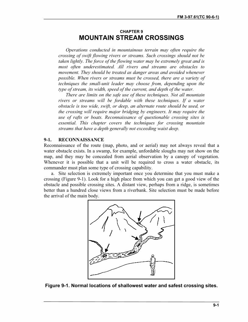
FM 3-97.61(TC 90-6-1)
9-1
CHAPTER 9MOUNTAIN STREAM CROSSINGS
Operations conducted in mountainous terrain may often require thecrossing of swift flowing rivers or streams. Such crossings should not betaken lightly. The force of the flowing water may be extremely great and ismost often underestimated. All rivers and streams are obstacles tomovement. They should be treated as danger areas and avoided wheneverpossible. When rivers or streams must be crossed, there are a variety oftechniques the small-unit leader may choose from, depending upon thetype of stream, its width, speed of the current, and depth of the water.
There are limits on the safe use of these techniques. Not all mountainrivers or streams will be fordable with these techniques. If a waterobstacle is too wide, swift, or deep, an alternate route should be used, orthe crossing will require major bridging by engineers. It may require theuse of rafts or boats. Reconnaissance of questionable crossing sites isessential. This chapter covers the techniques for crossing mountainstreams that have a depth generally not exceeding waist deep.
9-1. RECONNAISSANCEReconnaissance of the route (map, photo, and or aerial) may not always reveal that awater obstacle exists. In a swamp, for example, unfordable sloughs may not show on themap, and they may be concealed from aerial observation by a canopy of vegetation.Whenever it is possible that a unit will be required to cross a water obstacle, itscommander must plan some type of crossing capability.
a. Site selection is extremely important once you determine that you must make acrossing (Figure 9-1). Look for a high place from which you can get a good view of theobstacle and possible crossing sites. A distant view, perhaps from a ridge, is sometimesbetter than a hundred close views from a riverbank. Site selection must be made beforethe arrival of the main body.
Figure 9-1. Normal locations of shallowest water and safest crossing sites.

FM 3-97.61
9-2
b. A dry crossing on fallen timber or log jams is preferable to attempting a wetcrossing. Depending upon the time of year, the closer you are to the source, orheadwaters, the better your chances are of finding a natural snow or ice bridge forcrossing. If a dry crossing is unavailable, the following considerations should be made:
(1) The time of day the crossing can be an important factor. Although early morningis generally best because the water level is normally lower during this period, recentweather is a big factor; there may have been heavy rain in the last eight hours. Asglaciers, snow, or ice melt during the day, the rivers rise, reaching their maximum heightbetween mid afternoon and late evening, depending on the distance from the source.Crossings, if made during the early morning, will also allow clothing to dry more quicklyduring the heat of the day.
(2) A crossing point should normally be chosen at the widest, and thus shallowest,point of the river or stream. Sharp bends in the river should be avoided since the water islikely to be deep and have a strong current on the outside of the bend. Crossings will beeasiest on a smooth, firm bottom. Large rocks and boulders provide poor footing andcause a great deal of turbulence in the water.
(3) Many mountain streams, especially those which are fed by glacier run-off, containsections with numerous channels. It is often easier to select a route through these braidedsections rather than trying to cross one main channel. A drawback to crossing thesebraided channels, however, is the greater distance to the far bank may increase exposuretime and often the sand and gravel bars between the channels will offer little cover orconcealment, if any.
(4) The crossing site should have low enough banks on the near and far side to allowa man carrying equipment to enter and exit the stream with relative ease. If a handline orrope bridge is to be constructed, the crossing site should have suitable anchors on the nearand far bank, along with safe loading and unloading areas. Natural anchors are not anecessity, however the time required to find a site with solid natural anchors willprobably be less than the time required to construct artificial anchors. In some areas,above the tree line for example, artificial anchors may have to be constructed. Deadmananchors buried in the ground, or under a large pile of boulders work well.
(5) Log jams and other large obstructions present their own hazards. Logs floatingdownstream will generally get hung up in shallower sections creating the jam. Once a logjam is formed, however, the water forced to flow around it will erode the stream bottom.Eventually deep drop-offs or holes may develop, especially around the sides and off thedownstream end of the log jam. A log jam that totally bridges a section of the stream maybe the best way to cross. A wet crossing in the vicinity of a log jam should be performeda good distance below or above it. Some things to consider when crossing near logjams are:
• Cross well to the downstream side when possible.• Keep a sharp lookout for floating timber that could knock you off your feet.• If you must cross on the upstream side, stay well upstream from the log jam.
If a person is swept off his feet and caught in the debris of the jam, he couldeasily drown. A handline will greatly increase safety here.
(6) When possible, select a crossing site that has enough natural protection on thenear and far banks so that security teams may be placed out and enough cover andconcealment is available for the size of the element making the crossing. When cover and
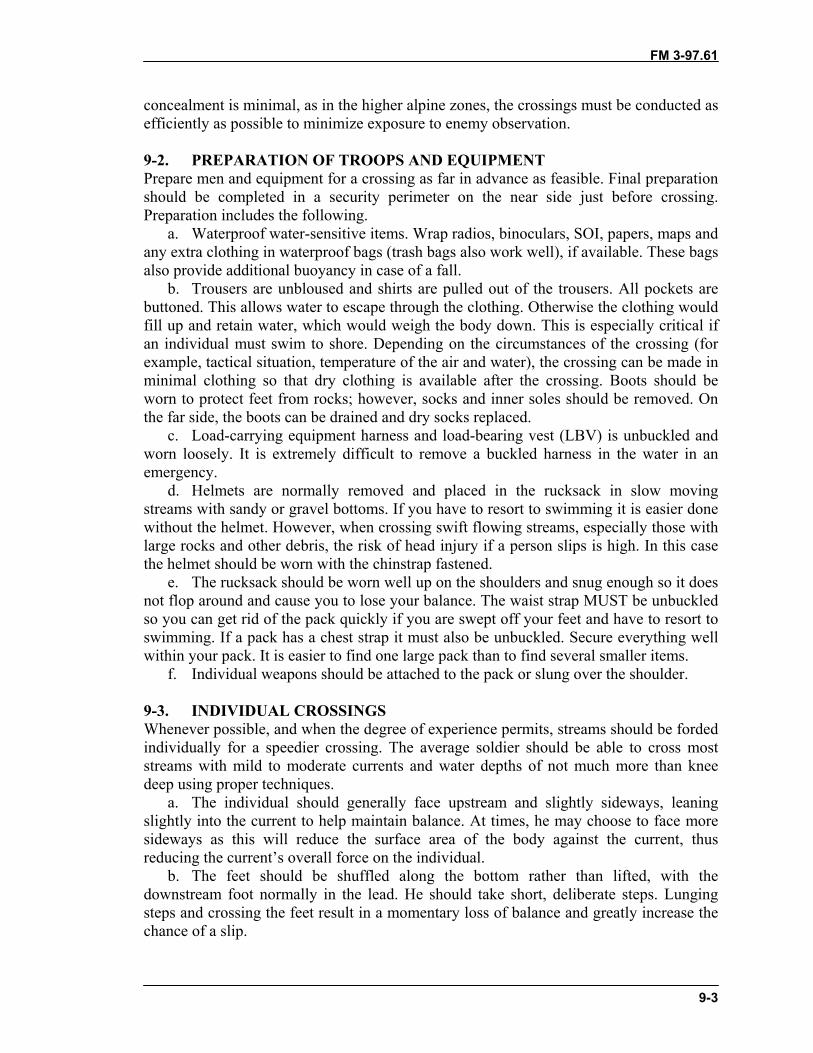
FM 3-97.61
9-3
concealment is minimal, as in the higher alpine zones, the crossings must be conducted asefficiently as possible to minimize exposure to enemy observation.
9-2. PREPARATION OF TROOPS AND EQUIPMENTPrepare men and equipment for a crossing as far in advance as feasible. Final preparationshould be completed in a security perimeter on the near side just before crossing.Preparation includes the following.
a. Waterproof water-sensitive items. Wrap radios, binoculars, SOI, papers, maps andany extra clothing in waterproof bags (trash bags also work well), if available. These bagsalso provide additional buoyancy in case of a fall.
b. Trousers are unbloused and shirts are pulled out of the trousers. All pockets arebuttoned. This allows water to escape through the clothing. Otherwise the clothing wouldfill up and retain water, which would weigh the body down. This is especially critical ifan individual must swim to shore. Depending on the circumstances of the crossing (forexample, tactical situation, temperature of the air and water), the crossing can be made inminimal clothing so that dry clothing is available after the crossing. Boots should beworn to protect feet from rocks; however, socks and inner soles should be removed. Onthe far side, the boots can be drained and dry socks replaced.
c. Load-carrying equipment harness and load-bearing vest (LBV) is unbuckled andworn loosely. It is extremely difficult to remove a buckled harness in the water in anemergency.
d. Helmets are normally removed and placed in the rucksack in slow movingstreams with sandy or gravel bottoms. If you have to resort to swimming it is easier donewithout the helmet. However, when crossing swift flowing streams, especially those withlarge rocks and other debris, the risk of head injury if a person slips is high. In this casethe helmet should be worn with the chinstrap fastened.
e. The rucksack should be worn well up on the shoulders and snug enough so it doesnot flop around and cause you to lose your balance. The waist strap MUST be unbuckledso you can get rid of the pack quickly if you are swept off your feet and have to resort toswimming. If a pack has a chest strap it must also be unbuckled. Secure everything wellwithin your pack. It is easier to find one large pack than to find several smaller items.
f. Individual weapons should be attached to the pack or slung over the shoulder.
9-3. INDIVIDUAL CROSSINGSWhenever possible, and when the degree of experience permits, streams should be fordedindividually for a speedier crossing. The average soldier should be able to cross moststreams with mild to moderate currents and water depths of not much more than kneedeep using proper techniques.
a. The individual should generally face upstream and slightly sideways, leaningslightly into the current to help maintain balance. At times, he may choose to face moresideways as this will reduce the surface area of the body against the current, thusreducing the current’s overall force on the individual.
b. The feet should be shuffled along the bottom rather than lifted, with thedownstream foot normally in the lead. He should take short, deliberate steps. Lungingsteps and crossing the feet result in a momentary loss of balance and greatly increase thechance of a slip.

FM 3-97.61
9-4
c. The individual should normally cross at a slight downstream angle so as not tofight the current. There is normally less chance of a slip when stepping off with thecurrent as opposed to stepping off against the current.
d. The individual must constantly feel for obstacles, holes and drop-offs with thelead foot and adjust his route accordingly. If an obstacle is encountered, the feet shouldbe placed on the upstream side of it where the turbulence is less severe and the waternormally shallower.
e. To increase balance, and if available, a long ice ax, sturdy tree limb, or other staffcan be used to give the individual a third point of contact (Figure 9-2). The staff shouldbe used on the upstream side of the individual and slightly leaned upon for support. Thestaff should be moved first, then the feet shuffled forward to it. This allows two points ofcontact to be maintained with the streambed at all times. The individual still moves at adownstream angle with the downstream foot in the lead.
Figure 9-2. Individual crossing with staff.
9-4. TEAM CROSSINGWhen the water level begins to reach thigh deep, or anytime the current is too swift forpersonnel to safely perform an individual crossing, a team crossing may be used. Forchain crossing, two or more individuals cross arms with each other and lock their handsin front of themselves (Figure 9-3). The line formed faces the far bank. The largestindividual should be on the upstream end of the line to break the current for the group.The line formed will then move across the stream using the same principles as forindividual crossings, but with the added support of each other. The line should crossparallel to the direction of the current. The team still moves at a slight downstream angle,stepping off with the downstream foot in the lead.
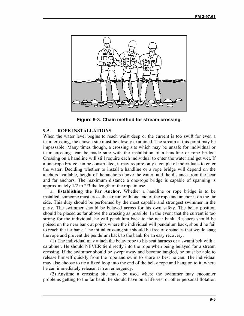
FM 3-97.61
9-5
Figure 9-3. Chain method for stream crossing.
9-5. ROPE INSTALLATIONSWhen the water level begins to reach waist deep or the current is too swift for even ateam crossing, the chosen site must be closely examined. The stream at this point may beimpassable. Many times though, a crossing site which may be unsafe for individual orteam crossings can be made safe with the installation of a handline or rope bridge.Crossing on a handline will still require each individual to enter the water and get wet. Ifa one-rope bridge can be constructed, it may require only a couple of individuals to enterthe water. Deciding whether to install a handline or a rope bridge will depend on theanchors available, height of the anchors above the water, and the distance from the nearand far anchors. The maximum distance a one-rope bridge is capable of spanning isapproximately 1/2 to 2/3 the length of the rope in use.
a. Establishing the Far Anchor. Whether a handline or rope bridge is to beinstalled, someone must cross the stream with one end of the rope and anchor it on the farside. This duty should be performed by the most capable and strongest swimmer in theparty. The swimmer should be belayed across for his own safety. The belay positionshould be placed as far above the crossing as possible. In the event that the current is toostrong for the individual, he will pendulum back to the near bank. Rescuers should bepoised on the near bank at points where the individual will pendulum back, should he failto reach the far bank. The initial crossing site should be free of obstacles that would snagthe rope and prevent the pendulum back to the bank for an easy recovery.
(1) The individual may attach the belay rope to his seat harness or a swami belt with acarabiner. He should NEVER tie directly into the rope when being belayed for a streamcrossing. If the swimmer should be swept away and become tangled, he must be able torelease himself quickly from the rope and swim to shore as best he can. The individualmay also choose to tie a fixed loop into the end of the belay rope and hang on to it, wherehe can immediately release it in an emergency.
(2) Anytime a crossing site must be used where the swimmer may encounterproblems getting to the far bank, he should have on a life vest or other personal flotation

FM 3-97.61
9-6
device (PFD). If the swimmer must release the rope at any time, he will have to rely onhis own water survival skills and swimming ability to get to shore. A PFD will greatlyincrease his own personal safety. A PFD may also be used by the last man across, as hewill release the rope from the anchor and be belayed across as the first man
b. Installation of a Handline. If it is possible to use a rope high enough above thewater to enable soldiers to perform a dry crossing, then a rope bridge should be installedas such. If this is impossible, and the rope must be installed to assist in a wet crossing,then it should be installed as a handline (Figure 9-4).
(1) The far anchor should be downstream from the near anchor so that the rope willrun at an angle downstream from the near anchor, approximately thirty to forty-fivedegrees, rather than straight across the stream. Here again, it is easier to move with thecurrent as opposed to directly across or against it.
(2) The rope may be anchored immediately on the far bank, pulled tight, andanchored on the near bank, or it may be installed with a transport tightening system if atighter rope is required.
(3) Crossing will always be performed on the downstream side of the handline,shuffling the feet with the downstream foot in the lead.
(4) A second climbing rope is used as a belay (Figure 9-5). One end of the belay ropewill be on the near bank and the other end on the far bank. It should be sent across withthe strong-swimmer. An appropriate knot is tied into the middle of the belay rope to formtwo fixed loops with each loop being approximately 6 inches long. One loop is connectedto the handline with carabiner(s) and the individual crossing connects one loop tohimself. The loops are short enough so the individual is always within arms reach of thehandline should he slip and let go. The individuals are belayed from both the near and farbanks. If a mishap should occur the individual can be retrieved from either shore,whichever appears easiest. The belay on the opposite shore can be released allowing theindividual to pendulum to the bank. It is important that the belay rope NOT be anchoredor tied to the belayer so that it may be quickly released if necessary.
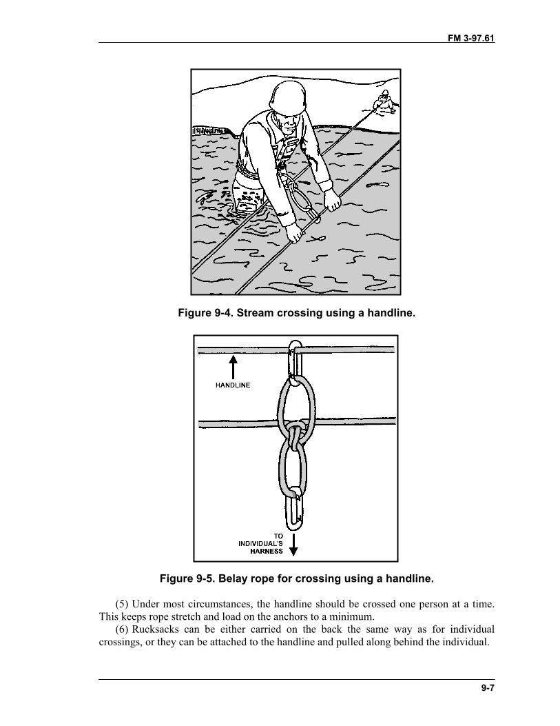
FM 3-97.61
9-7
Figure 9-4. Stream crossing using a handline.
Figure 9-5. Belay rope for crossing using a handline.
(5) Under most circumstances, the handline should be crossed one person at a time.This keeps rope stretch and load on the anchors to a minimum.
(6) Rucksacks can be either carried on the back the same way as for individualcrossings, or they can be attached to the handline and pulled along behind the individual.

FM 3-97.61
9-8
(7) If a large amount of equipment must be moved across the stream, especiallyheavier weapons, such as mortars, recoilless rifles, and so on, then a site should beselected to install a rope bridge.
9-6. SAFETYRiver and stream crossings present one of the most hazardous situations faced by themilitary mountaineer. The following safety procedures are minimum guidelines thatshould be followed when conducting a river or stream crossing.
a. All weak and nonswimmers should be identified before a crossing so that strongerswimmers may give assistance in crossing.
b. Not every river or stream can be crossed safely. It is always possible to cross at adifferent time or place, use a different technique, or choose another route.
c. The technique used is directly dependent upon water depth, speed of the current,stream bottom configuration, width of the stream, and individual experience.
d. The safest methods of crossing are always with the use of a handline or one-ropebridge.
e. If the installation of a handline or rope bridge becomes too difficult at a givencrossing site, then that site should be considered too hazardous and another site selected.
f. A lookout should be posted 50 to 100 meters upstream to watch for any obstaclesthat may be carried downstream and interfere with the crossing.
g. When conducting individual crossings (those without a handline or rope bridge),lifeguards should be posted downstream with poles or ropes prepared to throw, forassistance or rescue.
h. When the unit knows a rope installation will be required for crossing, at least twolife vests or other PFDs should be on hand to provide additional safety for the strongswimmer who must establish the far anchor, and the last man across who retrieves thesystem.
9-7. SWIMMINGThere are times when you might be alone and have no choice but to swim across, or theremay be a time that you find yourself suddenly plunged into a swift river or rapids. Ineither case, the following techniques could save your life.
a. Immediately jettison any equipment or clothing that restricts movement.b. Do not try to fight the current. Maneuver towards shore in a position with the feet
downstream, facing downstream, and fanning the hands alongside the body to addbuoyancy and to fend off submerged rocks. Use the feet to protect the rest of the bodyand to fend off submerged rocks.
c. Keep the head above water to observe for obstacles and attempt to maneuveraway from them.
d. Try to avoid backwater eddies and converging currents as they often containdangerous swirls. Avoid bubbly water under falls as it has little buoyancy. Breathbetween the wave troughs.
e. If the shore is too difficult to reach, seek out the closest and safest spot, such as asandbar, to get yourself out of the water as quickly as possible. Hypothermia will set inquickly in colder waters.

FM 3-97.61(TC 90-6-1)
10-1
CHAPTER 10MOVEMENT OVER SNOW AND ICE
Movement over snow- and ice-covered slopes presents its own uniqueproblems. Movement on steeper slopes requires an ice ax, crampons, andthe necessary training for this equipment. Personnel will also have tolearn how to place solid anchors in snow and ice to protect themselvesduring these movements if roped. Snow-covered glaciers present crevassefall hazards even when the slope is relatively flat, requiring personnel tolearn unique glacier travel and crevasse rescue techniques.
All the principles of rock climbing, anchor placement, belays, andrope usage discussed throughout the previous chapters apply to snow andice climbing as well. This chapter will focus on the additional skills andtechniques required to move safely through snow-covered mountains andover glaciated terrain.
10-1. MOVEMENT OVER SNOWThe military mountaineer must be equally adept on both snow and ice due to routenecessity and rapidly changing conditions. On steep slopes in deep snow, the climbermay climb straight up facing the slope. The ice ax shaft, driven directly into the snow,provides a quick and effective self-belay in case of a slip—the deeper the shaft penetratesthe snow, the better the anchor (Figure 10-1). It is usually best, however, to climb snow-covered slopes in a traversing fashion in order to conserve energy, unless there issignificant avalanche danger.
Figure 10-1. Self-belay on snow.

FM 3-97.61
10-2
a. The progression from walking on flat terrain to moving on steep terrain is thesame as for moving over snow-free terrain. If the snow is packed the sole of the boot willgenerally hold by kicking steps, even on steep slopes. Where it is difficult to make aneffective step with the boot, a cut made with the adze of the ice ax creates an effectivestep. In these situations crampons should be used for faster and easier movement.
b. When descending on snow, one can usually come straight downhill, even on steepterrain. Movement downhill should be slow and deliberate with the climber using an evenpace. The heels should be kicked vigorously into the snow. The body may be kept erectwith the aid of an ice ax, which may be jammed into the snow at each step for additionalsafety. Here again, crampons or step cutting may be necessary. A technique known asglissading may also be used as an easy method of descent and is covered in detail later inthis chapter.
10-2. MOVEMENT OVER ICEIce is found in many areas of mountains when snow is present, and during the summermonths also where perennial snowpack exists. Many times an ice area will be downslopeof a snowfield and sometimes the ice pack itself will be lightly covered with snow. Evenif using an ice ax and or crampons, movement will still be difficult without propertraining.
10-3. USE OF ICE AX AND CRAMPONSMovement over snow and ice is almost impossible without an ice ax and or crampons.
a. Ice Ax. When walking on snow or ice, the ice ax can be used as a third point ofcontact. When the terrain steepens, there are a number of ways to use the ice ax for snowor ice climbing. Some positions are more effective than others, depending on the intendedresult. You may find other ways to hold and use the ax, as long the security remains ineffect.
(1) Cane Position. The ice ax can be used on gentle slopes as a walking stick or cane(Figure 10-2). The ax is held by the head with the spike down and the pick facing to therear in preparation for self-arrest. When moving up or down gentle slopes the ice ax isplaced in front as the third point of contact, and the climber moves toward it. Whentraversing, the ax is held on the uphill side, in preparation for a self-arrest.

FM 3-97.61
10-3
Figure 10-2. Using the ice ax in the cane position.
(2) Cross Body Position or Port Arms Position. On steeper slopes the ax can be usedin the port arms position, or cross body position (Figure 10-3). It is carried across thechest, upslope hand on the shaft, spike towards the slope. The head of the ax is held awayfrom the slope with the pick to the rear in preparation for self-arrest. Ensure the leash isconnected to the upslope hand, which allows the ax to be used in the hammer position onthe upslope side of the climber. The spike, in this case, is used as an aid for maintainingbalance.
Figure 10-3. Ice ax in the cross body or port arms position.

FM 3-97.61
10-4
(3) Anchor Position. As the slope continues to steepen, the ax may be used in theanchor position (Figure 10-4). The head is held in the upslope hand and the pick is driveninto the slope. The spike is held in the downhill hand and pulled slightly away from theslope to increase the “bite” of the pick into the ice. If the climber is wearing a harness, thepick can be deeply inserted in the ice or hard snow and the ax leash could be connected tothe tie-in point on the harness for an anchor (ensure the ax is placed for the intendeddirection of pull).
Figure 10-4. Ice ax in the anchor position.
(4) Push-Hold Position. Another variation on steep slopes is the push-hold position(Figure 10-5). The hand is placed on the shaft of the ax just below the head with the pickforward. The pick is driven into the slope at shoulder height. The hand is then placed onthe top of the ax head for use as a handhold.

FM 3-97.61
10-5
Figure 10-5. Ice ax in the push-hold position.
(5) Dagger Position. The dagger position is used on steep slopes to place a handholdabove shoulder height (Figure 10-6). The hand grasps the head of the ax with the pickforward and the shaft hanging down. The ax is driven into the surface in a stabbingaction. The hand is then placed on the ax head for use as a handhold.
Figure 10-6. Ice ax in the dagger position.
(6) Hammer Position. The hammer position will set the pick deepest in any snow orice condition (Figure 10-7, page 10-6). The ax is used like a hammer with the pick beingdriven into the slope. On vertical or near-vertical sections, two axes used in the hammerposition will often be required.
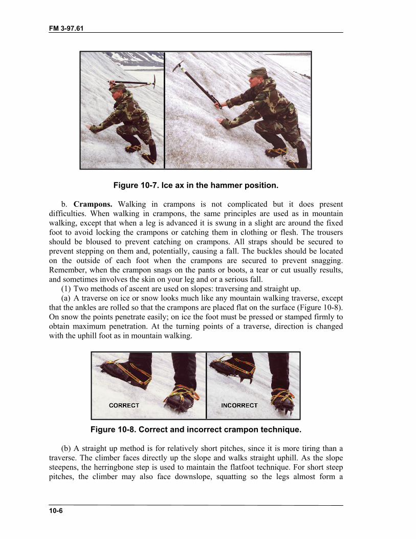
FM 3-97.61
10-6
Figure 10-7. Ice ax in the hammer position.
b. Crampons. Walking in crampons is not complicated but it does presentdifficulties. When walking in crampons, the same principles are used as in mountainwalking, except that when a leg is advanced it is swung in a slight arc around the fixedfoot to avoid locking the crampons or catching them in clothing or flesh. The trousersshould be bloused to prevent catching on crampons. All straps should be secured toprevent stepping on them and, potentially, causing a fall. The buckles should be locatedon the outside of each foot when the crampons are secured to prevent snagging.Remember, when the crampon snags on the pants or boots, a tear or cut usually results,and sometimes involves the skin on your leg and or a serious fall.
(1) Two methods of ascent are used on slopes: traversing and straight up.(a) A traverse on ice or snow looks much like any mountain walking traverse, except
that the ankles are rolled so that the crampons are placed flat on the surface (Figure 10-8).On snow the points penetrate easily; on ice the foot must be pressed or stamped firmly toobtain maximum penetration. At the turning points of a traverse, direction is changedwith the uphill foot as in mountain walking.
Figure 10-8. Correct and incorrect crampon technique.
(b) A straight up method is for relatively short pitches, since it is more tiring than atraverse. The climber faces directly up the slope and walks straight uphill. As the slopesteepens, the herringbone step is used to maintain the flatfoot technique. For short steeppitches, the climber may also face downslope, squatting so the legs almost form a

FM 3-97.61
10-7
90-degree angle at the knees, driving the spike of the ice ax into the slope at hip level,and then moving the feet up to the ax. By repeating these steps, the ax and cramponcombination can be used to climb short, steep pitches without resorting to step cutting.This method can be tiring. The technique is similar to the crab position used for climbingon slab rock and can also be used for short descents.
(2) A technique known as “front-pointing” may be used for moving straight uphill(Figure 10-9). It is especially useful on steep terrain, in combination with the ice ax in thepush-hold, dagger, or hammer position. Front-pointing is easiest with the use of morerigid mountain boots and rigid crampons. The technique is similar to doing calf raises onthe tips of the toes and is much more tiring than flat-footing.
(a) The technique starts with the feet approximately shoulder width apart. When astep is taken the climber places the front points of the crampons into the ice with the toeof the boot pointing straight into the slope.
(b) When the front points have bitten into the ice the heel of the boot is loweredslightly so that the first set of vertical points can also bite. The body is kept erect, with theweight centered over the feet as in climbing on rock.
Figure 10-9. Front-pointing with crampons.
c. Vertical Ice. When a climb on ice reaches the 60- to 70-degree angle, two iceaxes may be helpful, and will become necessary as the angle approaches 90 degrees. Thesame basic climbing techniques described in Chapter 6 should be applied. If leashes ofthe correct length and fit are attached to both axes, it may be possible to hang completelyfrom the axes while moving the feet.
d. Descending with Crampons and Ice Ax. Whenever possible, descend straightdown the fall line. As the slope steepens, gradually turn sideways; on steeper slopes, bendat the waist and knees as if sitting, keeping the feet flat to engage all vertical cramponpoints and keep the weight over the feet as in descending rock slab (Figures 10-10 and10-11, page 10-8). On steep terrain, assume a cross body or port arms position with theax, and traverse. The crab position or front-pointing may also be used for descending.Regardless of the technique used, always ensure the points of the crampons are inserted
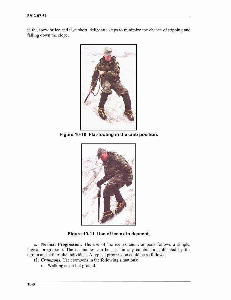
FM 3-97.61
10-8
in the snow or ice and take short, deliberate steps to minimize the chance of tripping andfalling down the slope.
Figure 10-10. Flat-footing in the crab position.
Figure 10-11. Use of ice ax in descent.
e. Normal Progression. The use of the ice ax and crampons follows a simple,logical progression. The techniques can be used in any combination, dictated by theterrain and skill of the individual. A typical progression could be as follows:
(1) Crampons. Use crampons in the following situations:• Walking as on flat ground.

FM 3-97.61
10-9
• Herringbone step straight up the slope.• Traverse with feet flat.• Backing up the slope (crab position).• Front-pointing.
(2) Ice Ax. Use the ice ax in these situations:• Cane position on flat ground.• Cane position on uphill side as slope steepens.• Port arms position with spike on uphill side.• Anchor position with pick on uphill side.• Push-hold position using front-pointing technique.• Dagger position using front-pointing technique.• Hammer position using front-pointing technique.
e. Climbing Sequence. Using most of these positions, a single ax can be “climbed”in steps to move upslope on low-angle to near vertical terrain (Figure 10-12). Begin bypositioning the feet in a secure stance and placing the ax in the hammer position as highas possible. Slowly and carefully move the feet to higher positions alternately, and movethe hand up the ax shaft. Repeat this until the hand is on top of the head of the ax.Remove the ax and place it at a higher position and begin again.
Figure 10-12. Climbing sequence.

FM 3-97.61
10-10
f. Step Cutting. Step cutting is an extremely valuable technique that is a requiredskill for any military mountaineer (Figure 10-13). Using cut steps can save valuable timethat would be spent in donning crampons for short stretches of ice and can, in some cases,save the weight of the crampons altogether. Steps may also have to be cut by the leadteam to enable a unit without proper equipment to negotiate snow- or ice-covered terrain.As units continue to move up areas where steps have been cut they should continue toimprove each step. In ascending, steps may be cut straight up the slope, although atraverse will normally be adopted. In descending, a traverse is also the preferred method.When changing direction, a step large enough for both feet and crampons must be made.Once the step is formed, the adze is best used to further shape and clean the step.
(1) Snow. On slopes of firm snow and soft ice, steps may be cut by swinging the axin a near-vertical plane, using the inside corner of the adze for cutting. The step should befashioned so that it slopes slightly inward and is big enough to admit the entire foot.Steps used for resting or for turning must be larger.
(2) Ice. Hard ice requires that the pick of the ax be used. Begin by directing a line ofblows at right angles to the slope to make a fracture line along the base of the intendedstep. This technique will reduce the chance of an unwanted fracture in the ice breakingout the entire step. Next, chop above the fracture line to fashion the step. When using thepick it should be given an outward jerk as it is placed to prevent it from sticking in theice.
(3) Step Cutting in a Traverse. When cutting steps in a traverse, the preferred cuttingsequence is to cut one step at an arm’s length from the highest step already cut, then cutone between those two. Cutting ahead one step then cutting an intermediate step keeps allof the steps relatively close to one another and maintains a suitable interval that allpersonnel can use.
(4) Handholds. If handholds are cut, they should be smaller than footholds, andangled more.
Figure 10-13. Step cutting and handhold cutting.

FM 3-97.61
10-11
g. Self-Arrest. The large number of climbers injured or killed while climbing onsnow and ice can be attributed to two major failings on the part of the climber: climbingunroped, and a lack of knowledge and experience in the techniques necessary to stop, orarrest, a fall (Figure 10-14). A climber should always carry an ice ax when climbing onsteep snow or ice; if a fall occurs, he must retain possession and control of his ice ax if heis to successfully arrest the fall. During movement on steep ice, the ax pick will be in theice solidly before the body is moved, which should prevent a fall of any significance (thisis a self belay not a self-arrest).
CAUTIONSelf-arrest requires the ax pick to gradually dig in toslow the descent. Self-arrest is difficult on steep icebecause the ice ax pick instantly “bites” into the ice,possibly resulting in either arm or shoulder injury, orthe ax is deflected immediately upon contact.
Figure 10-14. Self-arrest technique.

FM 3-97.61
10-12
Figure 10-14. Self-arrest technique (continued).
(1) A climber who has fallen may roll or spin; if this happens, the climber must firstgain control of his body, whether it is with his ice ax or simply by brute force. Once theroll or spin has been controlled, the climber will find himself in one of four positions.
• Head upslope, stomach on the slope, and feet pointed downslope.• Head upslope, back to the slope, and feet pointed downslope.• Head downslope, stomach on the slope, and feet pointed upslope.• Head downslope, back to the slope, and feet pointed upslope.
(2) To place the body in position to arrest from the four basic fall positions thefollowing must be accomplished.
(a) In the first position, the body is in proper relation to the slope for an arrest.(b) In the second position, the body must first be rotated from face up to face down
on the slope. This is accomplished by rolling the body toward the head of the ax.(c) In the third position, the pick of the ice ax is placed upslope and used as a pivot to
bring the body into proper position.(d) In the fourth position, the head of the ax must be driven into the snow to the
climber’s side. This will cause the body to rotate into a head up, stomach down position.(3) The final position when the arrest of the fall is completed should be with the head
upslope, stomach on the slope, with the feet pointed downslope. If crampons are not
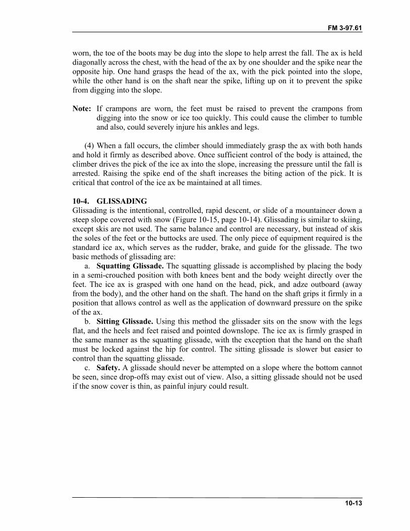
FM 3-97.61
10-13
worn, the toe of the boots may be dug into the slope to help arrest the fall. The ax is helddiagonally across the chest, with the head of the ax by one shoulder and the spike near theopposite hip. One hand grasps the head of the ax, with the pick pointed into the slope,while the other hand is on the shaft near the spike, lifting up on it to prevent the spikefrom digging into the slope.
Note: If crampons are worn, the feet must be raised to prevent the crampons fromdigging into the snow or ice too quickly. This could cause the climber to tumbleand also, could severely injure his ankles and legs.
(4) When a fall occurs, the climber should immediately grasp the ax with both handsand hold it firmly as described above. Once sufficient control of the body is attained, theclimber drives the pick of the ice ax into the slope, increasing the pressure until the fall isarrested. Raising the spike end of the shaft increases the biting action of the pick. It iscritical that control of the ice ax be maintained at all times.
10-4. GLISSADINGGlissading is the intentional, controlled, rapid descent, or slide of a mountaineer down asteep slope covered with snow (Figure 10-15, page 10-14). Glissading is similar to skiing,except skis are not used. The same balance and control are necessary, but instead of skisthe soles of the feet or the buttocks are used. The only piece of equipment required is thestandard ice ax, which serves as the rudder, brake, and guide for the glissade. The twobasic methods of glissading are:
a. Squatting Glissade. The squatting glissade is accomplished by placing the bodyin a semi-crouched position with both knees bent and the body weight directly over thefeet. The ice ax is grasped with one hand on the head, pick, and adze outboard (awayfrom the body), and the other hand on the shaft. The hand on the shaft grips it firmly in aposition that allows control as well as the application of downward pressure on the spikeof the ax.
b. Sitting Glissade. Using this method the glissader sits on the snow with the legsflat, and the heels and feet raised and pointed downslope. The ice ax is firmly grasped inthe same manner as the squatting glissade, with the exception that the hand on the shaftmust be locked against the hip for control. The sitting glissade is slower but easier tocontrol than the squatting glissade.
c. Safety. A glissade should never be attempted on a slope where the bottom cannotbe seen, since drop-offs may exist out of view. Also, a sitting glissade should not be usedif the snow cover is thin, as painful injury could result.

FM 3-97.61
10-14
Figure 10-15. Glissading techniques.
10-5. SNOW AND ICE ANCHORSIce and snow anchors consist of snow pickets, flukes, deadman-type anchors, ice screws,and ice pitons. Deadman anchors can be constructed from snowshoes, skis, backpacks,sleds, or any large items.
a. Ice Pitons. The ice piton is used to establish anchor points. The ice piton is notseen in modern ice climbing but may still be available to the military. The standard icepiton is made of tubular steel and is 10 inches in length. Ice pitons installed in pairs are abombproof anchor; however, ice pitons have no threads for friction to hold them in theice once placed and are removed easily. Safe use of ice pitons requires placement inpairs. Used singularly, ice pitons are a strong anchor but are easily removed, decreasingthe perceived security of the anchor. Follow the instructions below for placing ice pitonsin pairs.
(1) Cut a horizontal recess into the ice, and also create a vertical surface (two cleansurfaces at right angles to each other).
(2) Drive one piton into the horizontal surface and another into the vertical surface sothat the two pitons intersect at the necessary point (Figure 10-16).
(3) Connect the two rings with a single carabiner, ensuring the carabiner is not cross-loaded. Webbing or rope can be used if the rings are turned to the inside of theintersection.
(4) Test the piton pair to ensure it is secure. If it pulls out or appears weak, move toanother spot and replace it. The pair of pitons, when placed correctly, aremultidirectional.
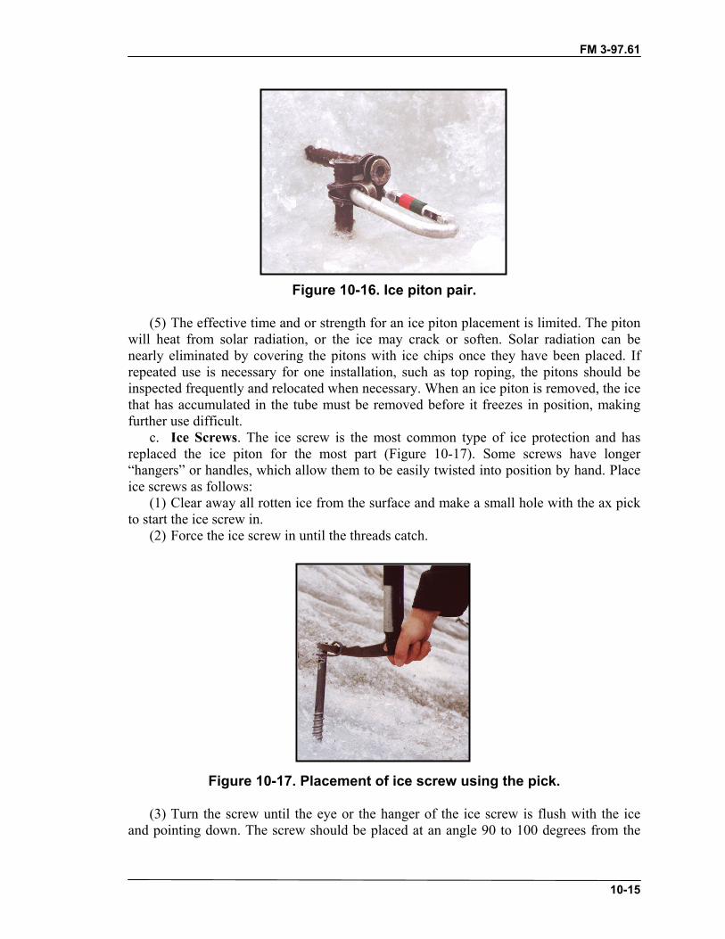
FM 3-97.61
10-15
Figure 10-16. Ice piton pair.
(5) The effective time and or strength for an ice piton placement is limited. The pitonwill heat from solar radiation, or the ice may crack or soften. Solar radiation can benearly eliminated by covering the pitons with ice chips once they have been placed. Ifrepeated use is necessary for one installation, such as top roping, the pitons should beinspected frequently and relocated when necessary. When an ice piton is removed, the icethat has accumulated in the tube must be removed before it freezes in position, makingfurther use difficult.
c. Ice Screws. The ice screw is the most common type of ice protection and hasreplaced the ice piton for the most part (Figure 10-17). Some screws have longer“hangers” or handles, which allow them to be easily twisted into position by hand. Placeice screws as follows:
(1) Clear away all rotten ice from the surface and make a small hole with the ax pickto start the ice screw in.
(2) Force the ice screw in until the threads catch.
Figure 10-17. Placement of ice screw using the pick.
(3) Turn the screw until the eye or the hanger of the ice screw is flush with the iceand pointing down. The screw should be placed at an angle 90 to 100 degrees from the

FM 3-97.61
10-16
lower surface. Use either your hand or the pick of the ice ax to screw it in. If you have ashort ax (70 centimeters or less), you may be able to use the spike in the eye or hanger toease the turning. (Remember that you may only have use of one hand at this pointdepending on your stance and the angle of the terrain.)
(4) As with ice pitons, melting of the ice around a screw over a period of time mustbe considered. The effective time and or strength of an ice screw placement is limited.The screw will heat from solar radiation, or the ice may crack or soften. Solar radiationcan be nearly eliminated by covering the screw with ice chips once it has been emplaced.If repeated use is necessary for one installation, such as top roping, the screws should beinspected frequently and relocated when necessary. When an ice screw is removed, theice that has accumulated in the tube, must be removed before further use.
d. Horseshoe or Bollard Anchor. This is an artificial anchor shaped generally likea horseshoe (Figure 10-18). It is formed from either ice or snow and constructed by eithercutting with the ice ax or stamping with the boots. When constructed of snow, the widthshould not be less than 10 feet. In ice, this width may be narrowed to 2 feet, depending onthe strength of the ice. The length of the bollard should be at least twice the width. Thetrench around the horseshoe should be stamped as deeply as possible in the snow andshould be cut not less than 6 inches into the ice after all rotten ice is removed. Thebackside of the anchor must always be undercut to prevent the rope from sliding off andover the anchor.
(1) This type of anchor is usually available and may be used for fixed ropes orrappels. It must be inspected frequently to ensure that the rope is not cutting through thesnow or ice more than one-third the length of the anchor; if it is, a new anchor must beconstructed in a different location.
(2) A horseshoe anchor constructed in snow is always precarious, its strengthdepending upon the prevailing texture of the snow. For dry or wind-packed snow, thereliability of the anchor should always be suspect. The backside of the bollard can bereinforced with ice axes, pickets, or other equipment for added strength.
Figure 10-18. Horseshoe or bollard anchor.

FM 3-97.61
10-17
e. Pickets and Ice Axes. Pickets and ice axes may be used as snow anchors asfollows.
(1) The picket should be driven into the snow at 5 to 15 degrees off perpendicularfrom the lower surface. If the picket cannot be driven in all the way to the top hole, thecarabiner should be placed in the hole closest to the snow surface to reduce leverage. Thepicket may also be tied off with a short loop of webbing or rope as in tying off pitons.
(2) An ice ax can be used in place of a picket. When using an ice ax as a snowanchor, it should be inserted with the widest portion of the ax shaft facing the direction ofpull. The simplest connection to the ax is to use a sling or rope directly around the shaftjust under the head. If using the leash ensure it is not worn, frayed, or cut from generaluse; is strong enough; and does not twist the ax when loaded. A carabiner can be clippedthrough the hole in the head, also.
(3) Whenever the strength of the snow anchor is suspect, especially when a picket orax cannot be driven in all the way, the anchor may be buried in the snow and used as a“dead man” anchor. Other items suitable for dead man anchor construction arebackpacks, skis, snowshoes, ski poles, or any other item large enough or shaped correctlyto achieve the design. A similar anchor, sometimes referred to as a “dead guy,” can bemade with a large sack either stuffed with noncompressible items or filled with snow andburied. Ensure the attaching point is accessible before burying. The direction of pull onlong items, such as a picket or ax, should be at a right angle to its length. Theconstruction is identical to that of the dead man anchor used in earth.
f. Equalized Anchors. Snow and ice anchors must be constantly checked due tomelting and changing snow or ice conditions.
(1) Whenever possible, two or more anchors should be used. While this is not alwayspractical for intermediate anchor points on lead climbs or fixed ropes, it should bemandatory for main anchors at all belay positions, rappel points, or other fixed ropeinstallations. (Figure 10-19, page 10-18, shows an example of three snow picketsconfigured to an equalized anchor.)
(2) As with multipoint anchors on rock, two or more snow or ice anchors can bejoined together with a sling rope or webbing to construct one solid, equalized anchor. Abowline on a bight tied into the climbing rope can also be used instead of sling ropes orwebbing.

FM 3-97.61
10-18
Figure 10-19. Equalized anchor using pickets.
10-6. ROPED CLIMBING ON ICE AND SNOWWhen climbing on ice or snow team members tie into a climbing rope the same as whenthey climb on rock. When crevasses are expected, a three-man rope team isrecommended.
a. Tie-In Method. For climbing on snow and ice, the tie-in procedure is normallythe same as for rock climbing; however, when moving over snow-covered glaciers, thetie-in is modified slightly. (See paragraph 10-7, Movement on Glaciers, for moreinformation).
b. Movement. For movement on gentle or moderate slopes where there is littlechance of a serious fall, all climbers move simultaneously. Normally the climbers movein single file using the steps created by the lead climber and improving them whennecessary. The rope between the climbers should be fully extended and kept reasonablytight. Should any member fall, he immediately yells “FALLING.” The other rope teammembers immediately drop into a self-arrest position. The fallen climber also applies theself-arrest procedure. By using this method, called the “team arrest,” the entire team as awhole arrests the fall of one member. On steeper slopes, and when crossing snow-covered crevasses where the snow bridges appear weak, the climbers use belayedclimbing techniques as in rock climbing.
c. Belaying on Snow and Ice. The principles of belaying on ice and snow are thesame as on rock. Generally, the high-force falls found in rock climbing are not present onsnow and ice unless the pitch being climbed is extremely steep.
(1) Boot-Ax Belay. This belay can be useful in areas where the full length of the iceax can penetrate the snow. The holding strength of the boot-ax belay is directly related tothe firmness of the snow and to the strength of the ice ax shaft. The shaft of the ax is

FM 3-97.61
10-19
tilted slightly uphill and jammed into the snow. The belayer places his uphill foot againstthe downhill side of the ax for support. A bight formed in the rope is placed over the bootand around the shaft of the ice ax. The brake is applied by wrapping the rope around theheel of the boot (Figure 10-20).
Figure 10-20. Boot-ax belay.
(2) Body Belay. The body belay can be used on snow and ice, also. The principles arethe same as for belays on rock—solid anchors must be used and a well-braced positionassumed. The position can be improved by digging depressions into the snow or ice for aseat and footholds. A strong platform should be constructed for the standing body belay.
(3) Munter Hitch. This belay technique is also used on snow and ice. When using thehitch off of the anchor, a two-point equalized anchor should be constructed as aminimum.
d. Fixed Ropes. The use of fixed ropes on ice is recommended for moving unitsthrough icefall areas on glaciers or other steep ice conditions. The procedures foremplacing fixed ropes on ice are basically the same as on rock with the exception thatanchors need more attention, both in initial placement and in subsequent inspection, andsteps may have to be cut to assist personnel.
10-7. MOVEMENT ON GLACIERSMovement in mountainous terrain may require travel on glaciers. An understanding ofglacier formation and characteristics is necessary to plan safe routes. A glacier is formedby the perennial accumulation of snow and other precipitation in a valley or draw. The
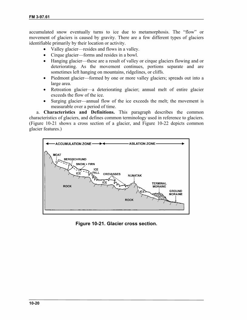
FM 3-97.61
10-20
accumulated snow eventually turns to ice due to metamorphosis. The “flow” ormovement of glaciers is caused by gravity. There are a few different types of glaciersidentifiable primarily by their location or activity.
• Valley glacier—resides and flows in a valley.• Cirque glacier—forms and resides in a bowl.• Hanging glacier—these are a result of valley or cirque glaciers flowing and or
deteriorating. As the movement continues, portions separate and aresometimes left hanging on mountains, ridgelines, or cliffs.
• Piedmont glacier—formed by one or more valley glaciers; spreads out into alarge area.
• Retreation glacier—a deteriorating glacier; annual melt of entire glacierexceeds the flow of the ice.
• Surging glacier—annual flow of the ice exceeds the melt; the movement ismeasurable over a period of time.
a. Characteristics and Definitions. This paragraph describes the commoncharacteristics of glaciers, and defines common terminology used in reference to glaciers.(Figure 10-21 shows a cross section of a glacier, and Figure 10-22 depicts commonglacier features.)
Figure 10-21. Glacier cross section.

FM 3-97.61
10-21
Figure 10-22. Glacier features.
(1) Firn is compacted granular snow that has been on the glacier at least one year.Firn is the building blocks of the ice that makes the glacier.
(2) The accumulation zone is the area that remains snow-covered throughout the yearbecause of year-round snowfall. The snowfall exceeds melt.
(3) The ablation zone is the area where the snow melts off the ice in summer. Meltequals or exceeds snowfall.
(4) The firn line separates the accumulation and ablation zones. As you approach thisarea, you may see “strips” of snow in the ice. Be cautious, as these could be snow bridgesremaining over crevasses. Remember that snow bridges will be weakest lower on theglacier as you enter the accumulation zone. The firn line can change annually.
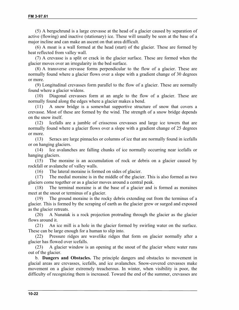
FM 3-97.61
10-22
(5) A bergschrund is a large crevasse at the head of a glacier caused by separation ofactive (flowing) and inactive (stationary) ice. These will usually be seen at the base of amajor incline and can make an ascent on that area difficult.
(6) A moat is a wall formed at the head (start) of the glacier. These are formed byheat reflected from valley wall.
(7) A crevasse is a split or crack in the glacier surface. These are formed when theglacier moves over an irregularity in the bed surface.
(8) A transverse crevasse forms perpendicular to the flow of a glacier. These arenormally found where a glacier flows over a slope with a gradient change of 30 degreesor more.
(9) Longitudinal crevasses form parallel to the flow of a glacier. These are normallyfound where a glacier widens.
(10) Diagonal crevasses form at an angle to the flow of a glacier. These arenormally found along the edges where a glacier makes a bend.
(11) A snow bridge is a somewhat supportive structure of snow that covers acrevasse. Most of these are formed by the wind. The strength of a snow bridge dependson the snow itself.
(12) Icefalls are a jumble of crisscross crevasses and large ice towers that arenormally found where a glacier flows over a slope with a gradient change of 25 degreesor more.
(13) Seracs are large pinnacles or columns of ice that are normally found in icefallsor on hanging glaciers.
(14) Ice avalanches are falling chunks of ice normally occurring near icefalls orhanging glaciers.
(15) The moraine is an accumulation of rock or debris on a glacier caused byrockfall or avalanche of valley walls.
(16) The lateral moraine is formed on sides of glacier.(17) The medial moraine is in the middle of the glacier. This is also formed as two
glaciers come together or as a glacier moves around a central peak.(18) The terminal moraine is at the base of a glacier and is formed as moraines
meet at the snout or terminus of a glacier.(19) The ground moraine is the rocky debris extending out from the terminus of a
glacier. This is formed by the scraping of earth as the glacier grew or surged and exposedas the glacier retreats.
(20) A Nunatak is a rock projection protruding through the glacier as the glacierflows around it.
(21) An ice mill is a hole in the glacier formed by swirling water on the surface.These can be large enough for a human to slip into.
(22) Pressure ridges are wavelike ridges that form on glacier normally after aglacier has flowed over icefalls.
(23) A glacier window is an opening at the snout of the glacier where water runsout of the glacier.
b. Dangers and Obstacles. The principle dangers and obstacles to movement inglacial areas are crevasses, icefalls, and ice avalanches. Snow-covered crevasses makemovement on a glacier extremely treacherous. In winter, when visibility is poor, thedifficulty of recognizing them is increased. Toward the end of the summer, crevasses are
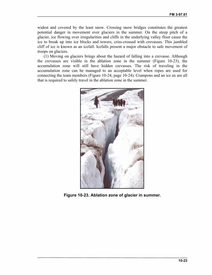
FM 3-97.61
10-23
widest and covered by the least snow. Crossing snow bridges constitutes the greatestpotential danger in movement over glaciers in the summer. On the steep pitch of aglacier, ice flowing over irregularities and cliffs in the underlying valley floor cause theice to break up into ice blocks and towers, criss-crossed with crevasses. This jumbledcliff of ice is known as an icefall. Icefalls present a major obstacle to safe movement oftroops on glaciers.
(1) Moving on glaciers brings about the hazard of falling into a crevasse. Althoughthe crevasses are visible in the ablation zone in the summer (Figure 10-23), theaccumulation zone will still have hidden crevasses. The risk of traveling in theaccumulation zone can be managed to an acceptable level when ropes are used forconnecting the team members (Figure 10-24, page 10-24). Crampons and an ice ax are allthat is required to safely travel in the ablation zone in the summer.
Figure 10-23. Ablation zone of glacier in summer.
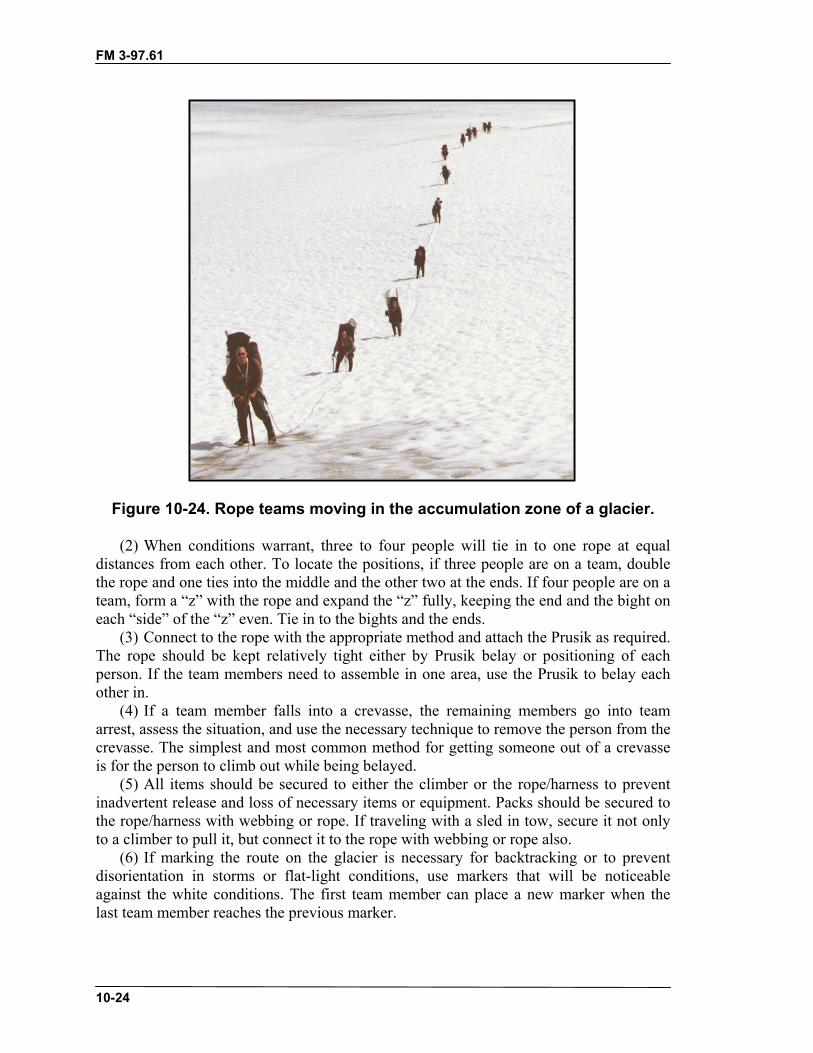
FM 3-97.61
10-24
Figure 10-24. Rope teams moving in the accumulation zone of a glacier.
(2) When conditions warrant, three to four people will tie in to one rope at equaldistances from each other. To locate the positions, if three people are on a team, doublethe rope and one ties into the middle and the other two at the ends. If four people are on ateam, form a “z” with the rope and expand the “z” fully, keeping the end and the bight oneach “side” of the “z” even. Tie in to the bights and the ends.
(3) Connect to the rope with the appropriate method and attach the Prusik as required.The rope should be kept relatively tight either by Prusik belay or positioning of eachperson. If the team members need to assemble in one area, use the Prusik to belay eachother in.
(4) If a team member falls into a crevasse, the remaining members go into teamarrest, assess the situation, and use the necessary technique to remove the person from thecrevasse. The simplest and most common method for getting someone out of a crevasseis for the person to climb out while being belayed.
(5) All items should be secured to either the climber or the rope/harness to preventinadvertent release and loss of necessary items or equipment. Packs should be secured tothe rope/harness with webbing or rope. If traveling with a sled in tow, secure it not onlyto a climber to pull it, but connect it to the rope with webbing or rope also.
(6) If marking the route on the glacier is necessary for backtracking or to preventdisorientation in storms or flat-light conditions, use markers that will be noticeableagainst the white conditions. The first team member can place a new marker when thelast team member reaches the previous marker.

FM 3-97.61
10-25
c. Roped Movement. The first rule for movement on glaciers is to rope up (Figure10-25). A roped team of two, while ideal for rock climbing, is at a disadvantage on asnow-covered glacier. The best combination is a three-man rope team. Generally, therope team members will move at the same time with the rope fully extended andreasonably tight between individuals, their security being the team arrest. If an individualshould break through a snow bridge and fall into a crevasse, the other membersimmediately perform self-arrest, halting the fall. At points of obvious weakness in thesnow bridges, the members may decide to belay each other across the crevasse using oneof the established belay techniques.
Figure 10-25. Preparation for roped movement.
(1) Even with proper training in crevasse rescue techniques, the probability exists thatan individual may remain suspended in a crevasse for a fairly lengthy amount of timewhile trying to get himself out or while awaiting help from his rope team members.Because of this, it is strongly recommended that all personnel wear a seat/chestcombination harness, whether improvised or premanufactured.
(2) Rope team members must be able to quickly remove the climbing rope from theharness(es) during a crevasse rescue. The standard practice for connecting to the rope forglacier travel is with a locking carabiner on a figure-eight loop to the harness. This allowsquick detachment of the rope for rescue purposes. The appropriate standing part of therope is then clipped to the chest harness carabiner.
(3) If a rope team consists of only two people, the rope should be divided into thirds,as for a four-person team. The team members tie into the middle positions on the rope,leaving a third of the rope between each team member and a third on each end of therope. The remaining “thirds” of the rope should be coiled and either carried in therucksack, attached to the rucksack, or carried over the head and shoulder. This gives each

FM 3-97.61
10-26
climber an additional length of rope that can be used for crevasse rescue, should one ofthe men fall through and require another rope. If necessary, this excess end rope can beused to connect to another rope team for safer travel.
Note: The self-arrest technique used by one individual will work to halt the fall of hispartner on a two-man rope team; however, the chance of it failing is much greater.Crevasse rescue procedures performed by a two-man rope team, by itself, may beextremely difficult. For safety reasons, movement over a snow-covered glacier bya single two-man team should be avoided wherever possible.
d. Use of Prusik Knots. Prusik knots are attached to the climbing rope for allglacier travel. The Prusiks are used as a self-belay technique to maintain a tight ropebetween individuals, to anchor the climbing rope for crevasse rescue, and for self-rescuein a crevasse fall. The Prusik slings are made from the 7-millimeter by 6-foot and7-millimeter by 12-foot ropes. The ends of the ropes are tied together, forming endlessloops or slings, with double fisherman’s knots. Form the Prusik knot on the rope in frontof the climber. An overhand knot can be tied into the sling just below the Prusik to keepequal tension on all the Prusik wraps. Attach this sling to the locking carabiner at the tiein point on the harness.
Note: An ascender can replace a Prusik sling in most situations. However, the weight ofan ascender hanging on the rope during movement will become annoying, and itcould be stepped on during movement and or climbing.
e. Securing the Backpack/Rucksack. If an individual should fall into a crevasse, itis essential that he be able to rid himself of his backpack. The weight of the average packwill be enough to hinder the climber during crevasse rescue, or possibly force him into anupside down position while suspended in the crevasse. Before movement, the packshould be attached to the climbing rope with a sling rope or webbing and a carabiner. Afallen climber can immediately drop the pack without losing it. The drop cord lengthshould be minimal to allow the fallen individual to reach the pack after releasing it, ifwarm clothing is needed. When hanging from the drop cord, the pack should be orientedjust as when wearing it (ensure the cord pulls from the top of the pack).
f. Routes. An individual operating in the mountains must appreciate certainlimitations in glacier movement imposed by nature.
(1) Additional obstacles in getting onto a glacier may be swift glacier streams, steepterminal or lateral moraines, and difficult mountain terrain bordering the glacier ice. Thesame obstacles may also have to be overcome in getting on and off a valley glacier at anyplace along its course.
(2) Further considerations to movement on a glacier are steep sections, heavilycrevassed portions, and icefalls, which may be major obstacles to progress. The use ofcurrent aerial photographs in conjunction with aerial reconnaissance is a valuable meansof gathering advance information about a particular glacier. However, they onlysupplement, and do not take the place of, on-the-ground reconnaissance conducted fromavailable vantage points.

FM 3-97.61
10-27
g. Crossing Crevasses. Open crevasses are obvious, and their presence is aninconvenience rather than a danger to movement. Narrow cracks can be jumped, providedthe take off and landing spots are firm and offer good footing. Wider cracks will have tobe circumvented unless a solid piece of ice joins into an ice bridge strong enough tosupport at least the weight of one member of the team. Such ice bridges are often formedin the lower portion of a crevasse, connecting both sides of it.
(1) In the area of the firn line, the zone that divides seasonal melting from permanentfalls of snow, large crevasses remain open, though their depths may be clogged withmasses of snow. Narrow cracks may be covered. In this zone, the snow, which coversglacier ice, melts more rapidly than that which covers crevasses. The difference betweenglacier ice and narrow snow-covered cracks is immediately apparent; the covering snowis white, whereas the glacier ice is gray.
(2) Usually the upper part of a glacier is permanently snow covered. The snowsurface here will vary in consistency from dry powder to consolidated snow. Below thissurface cover are found other snow layers that become more crystalline in texture withdepth, and gradually turn into glacier ice. It is in this snow-covered upper part of a glacierthat crevasses are most difficult to detect, for even wide crevasses may be completelyconcealed by snow bridges.
h. Snow Bridges. Snow bridges are formed by windblown snow that builds acornice over the empty interior of the crevasse. As the cornice grows from the windwardside, a counter drift is formed on the leeward side. The growth of the leeward portion willbe slower than that to the windward so that the juncture of the cornices occurs over themiddle of the crevasse only when the contributing winds blow equally from each side.Bridges can also be formed without wind, especially during heavy falls of dry snow.Since cohesion of dry snow depends only on an interlocking of the branches of delicatecrystals, such bridges are particularly dangerous during the winter. When warmerweather prevails the snow becomes settled and more compacted, and may form firmerbridges.
(1) Once a crevasse has been completely bridged, its detection is difficult. Bridges aregenerally slightly concave because of the settling of the snow. This concavity isperceptible in sunshine, but difficult to detect in flat light. If the presence of hiddencrevasses is suspected, the leader of a roped team must probe the snow in front of himwith the shaft of his ice ax. As long as a firm foundation is encountered, the team mayproceed, but should the shaft meet no opposition from an underlying layer of snow, acrevasse is probably present. In such a situation, the prober should probe closer to hisposition to make sure that he is not standing on the bridge itself. If he is, he should retreatgently from the bridge and determine the width and direction of the crevasse. He shouldthen follow and probe the margin until a more resistant portion of the bridge is reached.When moving parallel to a crevasse, all members of the team should keep well back fromthe edge and follow parallel but offset courses.
(2) A crevasse should be crossed at right angles to its length. When crossing a bridgethat seems sufficiently strong enough to hold a member of the team, the team willgenerally move at the same time on a tight rope, with each individual prepared to go intoself-arrest. If the stability of the snow bridge is under question, they should proceed asfollows for a team of three glacier travelers:
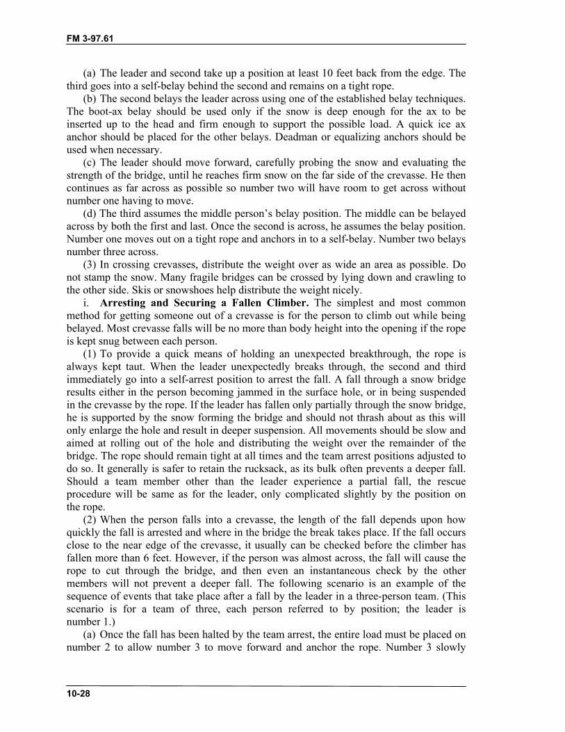
FM 3-97.61
10-28
(a) The leader and second take up a position at least 10 feet back from the edge. Thethird goes into a self-belay behind the second and remains on a tight rope.
(b) The second belays the leader across using one of the established belay techniques.The boot-ax belay should be used only if the snow is deep enough for the ax to beinserted up to the head and firm enough to support the possible load. A quick ice axanchor should be placed for the other belays. Deadman or equalizing anchors should beused when necessary.
(c) The leader should move forward, carefully probing the snow and evaluating thestrength of the bridge, until he reaches firm snow on the far side of the crevasse. He thencontinues as far across as possible so number two will have room to get across withoutnumber one having to move.
(d) The third assumes the middle person’s belay position. The middle can be belayedacross by both the first and last. Once the second is across, he assumes the belay position.Number one moves out on a tight rope and anchors in to a self-belay. Number two belaysnumber three across.
(3) In crossing crevasses, distribute the weight over as wide an area as possible. Donot stamp the snow. Many fragile bridges can be crossed by lying down and crawling tothe other side. Skis or snowshoes help distribute the weight nicely.
i. Arresting and Securing a Fallen Climber. The simplest and most commonmethod for getting someone out of a crevasse is for the person to climb out while beingbelayed. Most crevasse falls will be no more than body height into the opening if the ropeis kept snug between each person.
(1) To provide a quick means of holding an unexpected breakthrough, the rope isalways kept taut. When the leader unexpectedly breaks through, the second and thirdimmediately go into a self-arrest position to arrest the fall. A fall through a snow bridgeresults either in the person becoming jammed in the surface hole, or in being suspendedin the crevasse by the rope. If the leader has fallen only partially through the snow bridge,he is supported by the snow forming the bridge and should not thrash about as this willonly enlarge the hole and result in deeper suspension. All movements should be slow andaimed at rolling out of the hole and distributing the weight over the remainder of thebridge. The rope should remain tight at all times and the team arrest positions adjusted todo so. It generally is safer to retain the rucksack, as its bulk often prevents a deeper fall.Should a team member other than the leader experience a partial fall, the rescueprocedure will be same as for the leader, only complicated slightly by the position onthe rope.
(2) When the person falls into a crevasse, the length of the fall depends upon howquickly the fall is arrested and where in the bridge the break takes place. If the fall occursclose to the near edge of the crevasse, it usually can be checked before the climber hasfallen more than 6 feet. However, if the person was almost across, the fall will cause therope to cut through the bridge, and then even an instantaneous check by the othermembers will not prevent a deeper fall. The following scenario is an example of thesequence of events that take place after a fall by the leader in a three-person team. (Thisscenario is for a team of three, each person referred to by position; the leader isnumber 1.)
(a) Once the fall has been halted by the team arrest, the entire load must be placed onnumber 2 to allow number 3 to move forward and anchor the rope. Number 3 slowly
FM 3-97.61
10-29
releases his portion of the load onto number 2, always being prepared to go back intoself-arrest should number 2’s position begin to fail.
(b) Once number 2 is confident that he can hold the load, number 3 will proceed tonumber 2’s position, using the Prusik as a self belay, to anchor the rope. In this way therope remains reasonably tight between number 2 and number 3. Number 3 must alwaysbe prepared to go back into self-arrest should number 2’s position begin to fail.
(c) When number 3 reaches number 2’s position he will establish a bombproofanchor 3 to 10 feet in front of number 2 (on the load side), depending on how closenumber 2 is to the lip of the crevasse. This could be either a deadman or a two-pointequalized anchor, as a minimum.
(d) Number 3 connects the rope to the anchor by tying a Prusik with his long Prusiksling onto the rope leading to number 1. An overhand knot should be tied into the longPrusik sling to shorten the distance to the anchor, and attached to the anchor with acarabiner. The Prusik knot is adjusted toward the load.
(e) Number 2 can then release the load of number 1 onto the anchor. Number 2remains connected to the anchor and monitors the anchor.
(f) A fixed loop can be tied into the slack part of the rope, close to number 2, andattached to the anchor (to back up the Prusik knot).
(g) Number 3 remains tied in, but continues forward using a short Prusik as a self-belay. He must now quickly check on the condition of number 1 and decide which rescuetechnique will be required to retrieve him.
(3) These preliminary procedures must be performed before retrieving the fallenclimber. If number 3 should fall through a crevasse, the procedure is the same except thatnumber 1 assumes the role of number 3. Normally, if the middle person should fallthrough, number 1 would anchor the rope by himself. Number 3 would place the load onnumber 1’s anchor, then anchor his rope and move forward with a Prusik self-belay todetermine the condition of number 2.
j. Crevasse Rescue Techniques. Snow bridges are usually strongest at the edge ofthe crevasse, and a fall is most likely to occur some distance away from the edge. In somesituations, a crevasse fall will occur at the edge of the snow bridge, on the edge of the ice.If a fall occurs away from the edge, the rope usually cuts deeply into the snow, thusgreatly increasing friction for those pulling from above. In order to reduce friction, placepadding, such as an ice ax, ski, ski pole, or backpack/rucksack, under the rope and atright angles to the stress. Push the padding forward as far as possible toward the edge ofthe crevasse, thus relieving the strain on the snow. Ensure the padding is anchored fromfalling into the crevasse for safety of the fallen climber.
(1) Use of Additional Rope Teams. Another rope team can move forward and assistin pulling the victim out of a crevasse. The assisting rope team should move to a pointbetween the fallen climber and the remaining rope team members. The assisting team canattach to the arresting team’s rope with a Prusik or ascender and both rope teams’members can all pull simultaneously. If necessary, a belay can be initiated by the fallenclimber’s team while the assisting team pulls. The arresting team member closest to thefallen climber should attach the long Prusik to themselves and the rope leading to thefallen climber, and the assisting team can attach their Prusik or ascender between thislong Prusik and the arresting team member. As the assisting team pulls, the Prusik belaywill be managed by the arresting team member at the long Prusik.
FM 3-97.61
10-30
Note: Safety in numbers is obvious for efficient crevasse rescue techniques. Additionalrope teams have the necessary equipment to improve the main anchor or establishnew ones and the strength to pull a person out even if he is deep in the crevasse.Strength of other rope teams should always be used before establishing moretime-consuming and elaborate rescue techniques.
(2) Fixed Rope. If the fallen climber is not injured, he may be able to climb out on afixed rope. Number 1 clips number 3’s rope to himself. He then climbs out using number3’s rope as a simple fixed line while number 2 takes up the slack in number 1’s ropethrough the anchor Prusik for a belay.
(3) Prusik Ascending Technique. There may be times when the remaining membersof a rope team can render little assistance to the person in the crevasse. If poor snowconditions make it impossible to construct a strong anchor, the rope team members on topmay have to remain in self-arrest. Other times, it may just be easier for the fallen climberto perform a self-rescue. (Figure 10-26 shows the proper rope configuration.) Thetechnique is performed as follows:
(a) The fallen climber removes his pack and lets it hang below from the drop cord.(b) The individual slides their short Prusik up the climbing rope as far as possible.(c) The long Prusik is attached to the rope just below the short Prusik. The double
fisherman’s knot is spread apart to create a loop large enough for one or both feet. Thefallen climber inserts his foot/feet into the loop formed allowing the knot to cinch itselfdown.
(d) The individual stands in the foot loop, or “stirrup,” of the long sling.(e) With his weight removed from the short Prusik, it is slid up the rope as far as it
will go. The individual then hangs from the short Prusik while he moves the long Prusikup underneath the short Prusik again.
(f) The procedure is repeated, alternately moving the Prusiks up the rope, to ascendthe rope. Once the crevasse lip is reached, the individual can simply grasp the rope andpull himself over the edge and out of the hole.
(g) Besides being one of the simplest rope ascending techniques, the short Prusik actsas a self-belay and allows the climber to take as long a rest as he wants when sitting inthe harness. The rope should be detached from the chest harness carabiner to make themovements less cumbersome. However, it is sometimes desirable to keep the chestharness connected to the rope for additional support. In this case the Prusik knots must be“on top” of the chest harness carabiner so they can be easily slid up the rope withoutinterference from the carabiner. The long Prusik sling can be routed through the chestharness carabiner for additional support when standing up in the stirrup.

FM 3-97.61
10-31
Figure 10-26. Prusik ascending technique.
(4) Z-Pulley Hauling System. If a fallen climber is injured or unconscious, he willnot be able to offer any assistance in the rescue. If additional rope teams are notimmediately available, a simple raising system can be rigged to haul the victim out of thecrevasse. The Z-pulley hauling system is one of the simplest methods and the one mostcommonly used in crevasse rescue (Figure 10-27, page 10-32). The basic Z rig is a“3-to-1” system, providing mechanical advantage to reduce the workload on theindividuals operating the haul line. In theory, it would only take about 33 pounds of pullon the haul rope to raise a 100-pound load with this system. In actual field use, some ofthis mechanical advantage is lost to friction as the rope bends sharply around carabinersand over the crevasse lip. The use of mechanical rescue pulleys can help reduce thisfriction in the system. The following describes rigging of the system. (This scenario is fora team of three, each person referred to by position; the leader is number 1.)
(a) After the rope team members have arrested and secured number 1 to the anchor,and they have decided to install the Z rig, number 2 will attach himself to the anchorwithout using the rope and clear the connecting knot used. Number 3 remains connectedto the rope.
(b) The slack rope exiting the anchor Prusik is clipped into a separate carabinerattached to the anchor. A pulley can be used here if available.
(c) Number 3 will use number 2’s short Prusik to rig the haul Prusik. He movestoward the crevasse lip (still on his own self-belay) and ties number 2’s short Prusik ontonumber 1’s rope (load rope) as close to the edge as possible.

FM 3-97.61
10-32
(d) Another carabiner (and pulley if available) is clipped into the loop of the haulPrusik and the rope between number 3’s belay Prusik and the anchor is clipped (orattached through the pulley). Number 3’s rope becomes the haul rope.
(e) Number 3 then moves towards the anchor and number 2. Number 2 could helppull if necessary but first would connect to the haul rope with a Prusik just as number 3.If the haul Prusik reaches the anchor before the victim reaches the top, the load is simplyplaced back on the anchor Prusik and number 3 moves the haul Prusik back toward theedge. The system is now ready for another haul.
CAUTIONThe force applied to the fallen climber through use ofthe Z-pulley system can be enough to destroy theharness-to-rope connection or injure the fallen climberif excess force is applied to the pulling rope.
Notes: 1. The Z-pulley adds more load on the anchor due to the mechanical advantage.The anchor should be monitored for the duration of the rescue.
2. With the “3-to-1” system, the load (fallen climber) will be raised 1 foot forevery 3 feet of rope taken up during the haul.
Figure 10-27. Z-pulley hauling system.

FM 3-97.61
10-33
10-8. GLACIER BIVOUAC PROCEDURESWhen locating a bivouac site or a gathering area where the team might need or want tounrope, at least one person will need to “probe” the area for hidden crevasses. The besttype of probe will be the manufactured collapsing probe pole, at least eight feet in length.Other items could be used but the length and strength of the probe is most important.Other rope team members will belay the probers. The prober is “feeling” for a solidplatform to place the tent by pushing the probe as hard and deep as possible into thesurface. Probing should be in 2-foot intervals in all directions within the site.
a. If the probe suddenly has no resistance while pushing down, a crevasse is present.Attempts to outline the crevasse can be futile if the crevasse is large. Normally, the bestdecision is to relocate the proposed bivouac area far enough away to avoid that crevasse.(Sometimes only a few feet one way or the other is all that’s needed to reach a goodplatform.) Probe the tent site again after digging to the desired surface. Mark boundarieswith wands or other items such as skis, poles, and so on.
b. Occasionally while probing, increased pressure will be noticed without reaching asolid platform. The amount of snowfall may be such that even after digging into thesnow, the probe still doesn’t contact a hard surface. Try to find a solid platform.
c. There should be no unroped movement outside the probed/marked areas. If alatrine area is needed, probe a route away from the bivouac site and probe the latrine areaalso. If a dugout latrine is necessary, probe again after digging.
d. Multiple tent sites can be connected, which keeps tents closer together. Probe allareas between the tents if you plan to move in those areas. Closer tents will makecommunicating between tent groups and rope teams easier.
e. If there is a chance for severe storms with high winds, snow walls may beconstructed to protect the tent site from wind. The walls can be constructed from loosesnow piled on the perimeter, or blocks can be cut from consolidated snow layers. In deepsoft snow, digging three or four feet to find a consolidated layer will result in enoughsnow moved to build up decent walls around the tent site.
(1) For block construction, move the soft snow from the surface into the wallfoundation areas (down to a consolidated layer of snow).
(2) Cut blocks approximately 1 by 1 by 2 feet, and construct the walls by interlockingthe blocks with overlapping placements. The walls should be slightly higher than the tent.At a minimum, build walls on the windward side of the tent site.
(3) Snow walls can also provide shelter from wind for food preparation.
FM 3-97.61(TC 90-6-1)
11-1
CHAPTER 11MOUNTAIN RESCUE AND EVACUATION
Steep terrain and adverse weather are common in mountainousenvironments. Under these conditions, relatively minor injuries mayrequire evacuation. The evacuation technique chosen is determined by thetype of injury, distance to be moved, terrain, and existing installations. Airevacuation is preferred; however, the weather, tactical situation, oroperational ceiling of the aircraft may make this impossible. It is,therefore, imperative that all personnel are trained in mountainevacuation techniques and are self-sufficient. Casualties should be triagedbefore evacuation. Triage is performed by the most experienced medicalpersonnel available (physician, physician’s assistant, medic).
Performing a rescue operation can be a significant emotional event.Rescue scenarios must be practiced and rehearsed until rescue partymembers are proficient in the many tasks required to execute a rescue. Toperform most of the high-angle rescues, Level I and Level II mountaineersare required with a Level III supervising.
11-1. CONSIDERATIONSThe techniques of evacuation are proven techniques. They are, however, all subject toimprovement and should be discarded or modified as better methods of handling victimsare developed.
a. When evacuating a victim from mountainous areas keep in mind that the purposeof a rescue operation is to save a life, and physical risk to the rescuers must be weighedagainst this purpose. However, there is no excuse for failing to make the maximum effortwithin this limitation. Work and expense should be no deterrent when a life is at stake.
b. Rescues will be unplanned (improvised) or planned rescue operations. For aplanned rescue, equipment that is especially suited and designed for rescue should beused. For training missions always have a medical plan developed before an emergencyarises (plan for the worst and hope for the best). Ensure that the MEDEVAC plan is acomprehensive plan and must be thought out and understood by all that may be involvedin a potential rescue.
c. The following actions will be done immediately at the rescue scene.(1) Assume command. One person, and one person only, is overall in charge at all
times.(2) Prevent further injuries to the victim and to others. Use reasonable care in
reaching the victim.(3) Immediately ensure the victim has an open airway, resume victim’s breathing,
control serious bleeding, and maintain moderate body warmth. If the victim isunconscious, continually monitor pulse. Protect the patient from environmental hazards.
(4) Do not move the victim until you have ascertained the extent of injuries, unless itis necessary to prevent further injuries or the victim is located in a dangerous location(for example, avalanche run-out zone, hanging glacier, possibility of falling rocks).
(5) Do nothing more until you have thoroughly considered the situation. Resist theurge for action. Speed is less important than correct action.

FM 3-97.61
11-2
(6) Decide whether to evacuate with available facilities or to send for help. Speed ingetting to a hospital must be balanced against the probability of further injury if workingwith inexperienced people, lack of equipment or wrong equipment, and terrain at hand.
(7) When the evacuation route is long and arduous, a series of litter relay points orstations should be established. These stations must be staffed with the minimum medicalpersonnel to provide proper emergency treatment. When a victim develops signs of shockor worsens while being evacuated, he should be treated and retained at one of thesestations until his condition allows evacuation.
(8) Helicopters or heated vehicles, if available, should be used for evacuation. Whilethe use of aircraft or vehicles is preferred and can expedite a rescue operation, evacuationof a seriously wounded soldier should never be delayed to await aircraft, vehicle, or achange in weather.
11-2. PLANNING RESCUE OPERATIONSEvery commander should have a medical evacuation plan before undertaking anoperation. This plan should have contingencies included so as not to rely on asingle asset.
a. When rescuing a casualty (victim) threatened by hostile action, environmentalhazard, or any other immediate hazard, the rescuer should not take action without firstdetermining the extent of the hazard and his ability to handle the situation. THERESCUER MUST NOT BECOME A CASUALTY.
b. The rescue team leader must evaluate the situation and analyze the factorsinvolved. This evaluation can be divided into three major steps:
• Identify the task.• Evaluate the circumstances of the rescue.• Plan the action.
c. The task must be identified. In planning a rescue, the rescuer tries to obtain thefollowing information:
• Who, what, where, when, why, and how the situation happened.• Number of casualties by precedence (urgent, priority, routine, tactical
immediate), • number of casualties by type (litter or ambulatory), and the nature of their
injuries.• Terrain features and location of the casualties.• Tactical situation.• If adequate assistance is available to aid in security, rescue, treatment, and
evacuation.• If treatment can be provided at the scene; if the victims require movement to a
safer location.• Equipment required for the rescue operation.
d. Circumstances of the rescue are as follows:(1) After identifying the task, relate it to the circumstances of the situation.
• Are additional personnel, security, medical, or special rescue equipmentneeded?
• Are there circumstances, such as aircraft accidents (mass casualties), that mayrequire specialized skills?

FM 3-97.61
11-3
• What is the weather condition?• Is the terrain hazardous?• How much time is available?
(2) The time element may cause a rescuer to compromise planning stages ortreatment (beyond first aid). Make a realistic estimate of time available as quickly aspossible to determine the action time remaining. The key elements are the casualty’scondition and environment.
(3) Mass casualties are to be expected on the modern battlefield. All problems orcomplexities of rescue are now multiplied by the number of casualties. Time becomes thecritical element.
(4) Considerations for the main rescue group for a planned rescue are as follows:(a) Carry all needed equipment, hot food and drinks, stove, sleeping bags, tents,
bivouac sacks, warm clothes, ropes, and stretchers.(b) Prepare the evacuation route (ground transport to hospital, walking trails, fixed
lines, lowering lines, anchor points, and rescue belay points). If the victim is airlifted out,attach a paper with the medical actions that were performed on the ground (for example,blood pressure, pulse rate, drugs started, and so on).
(c) When performing all rescues, the rescuers are always tied in for safety. With allrescue techniques, remember to think things through logically for safety and to preventthe rescuer from accidentally untying himself or the fallen climber.
(d) Constantly inform the casualty (if they are conscious) as to what you are doingand what he must do.
e. The rescue plan should proceed as follows:(1) In estimating time available, the casualties’ ability to endure is of primary
importance. Age and physical condition may vary. Time available is a balance of theendurance time of the casualty, the situation, and the personnel and equipment available.
(2) Consider altitude and visibility. Maximum use of secure, reliable trails or roads is essential.
(3) Ensure that blankets and rain gear are available. Even a mild rain can complicatea normally simple rescue. In high altitudes, extreme cold, or gusting winds, availabletime is drastically reduced.
(4) High altitudes and gusting winds reduce the ability of fixed-wing or rotary-wingaircraft to assist in operations. Rotary-wing aircraft may be available to remove casualtiesfrom cliffs or inaccessible sites, and to quickly transport casualties to a medical treatmentfacility. Relying on aircraft or specialized equipment is a poor substitute for carefulplanning.
11-3. MASS CASUALTIESWhen there are mass casualties, an orderly rescue may involve further planning.
a. To manage a mass casualty rescue or evacuation, separate stages are taken.• FIRST STAGE: Remove personnel who are not trapped among debris or who
can be easily evacuated.• SECOND STAGE: Remove personnel who may be trapped by debris, but
whose extraction only requires the equipment on hand and little time.

FM 3-97.61
11-4
• THIRD STAGE: Remove the remaining personnel who are trapped inextremely difficult or time-consuming situations, such as moving largeamounts of debris or cutting through a wall.
• FOURTH STAGE: Remove dead personnel.b. Evacuation of wounded personnel is based on the victim’s condition and is
prioritized as follows:• PRIORITY ONE: Personnel with life-threatening injuries that require
immediate emergency care to survive; first aid and stabilization areaccomplished before evacuation.
• PRIORITY TWO: Personnel with injuries that require medical care but speedof evacuation is not essential.
• PRIORITY THREE: Injured personnel who can evacuate themselves withminimal assistance.
• PRIORITY FOUR: The logistics removal of dead personnel.
11-4. SPECIAL TRAININGBefore receiving training in basic mountain evacuation, litter teams should receiveinstruction in military mountaineering and basic first aid. Litter bearers and medics mustknow the use and care of rope as an item of equipment. The members of litter teams mustbe proficient in the techniques of belaying and choosing belay points. Proper support andprotection must be given to victims and litter bearers when evacuating over steep,difficult terrain.
11-5. PREPARATION FOR EVACUATIONAlthough the wounded soldier’s life may have been saved by applying first aid, it can belost through carelessness, rough handling, or inadequate protection from the elements.Therefore, before trying to move the wounded soldier, the type and extent of his injurymust be evaluated. Dressings over wounds must be reinforced, and fractured bones mustbe properly immobilized and supported. Based upon the evaluation of the type and extentof the soldier’s injury, the best method of manual transportation is selected.
11-6. MANUAL CARRIESPersonnel who are not seriously injured but cannot evacuate themselves may be assistedby fellow soldiers. Personnel who are injured and require prompt evacuation should notbe forced to wait for mobile evacuation or special equipment.
a. One-Man Carries. The basic carries taught in the Soldier’s Manual of CommonTasks (fireman’s carry, two-hand, four-hand, saddleback, piggyback, pistol belt, andponcho litter) are viable means of transporting injured personnel; however, themountainous terrain lends itself to several other techniques. One-man carries include thesling-rope carry and the rope coil carry.
(1) Sling-Rope Carry. The sling-rope carry (Figure 11-1) requires a 4.5-meter slingrope and two men—one as the bearer and the other as an assistant to help secure thecasualty to the bearer’s back. Conscious or unconscious casualties may be transportedthis way.
(a) The bearer kneels on all fours.

FM 3-97.61
11-5
(b) The assistant places the casualty face down on the bearer’s back ensuring thecasualty’s armpits are even with the bearer’s shoulders.
(c) The assistant then finds the middle of the sling rope and places it between thecasualty’s shoulders.
(d) The assistant runs the ends of the sling rope under the casualty’s armpits, crossesthe ends, and runs the ends over the bearer’s shoulders and back under the bearer’s arms.
(e) The assistant runs the ends of the rope between the casualty’s legs, around thecasualty’s thighs, and back around to the front of the bearer. The rope is tied with asquare knot with two overhand knots just above the bearer’s belt buckle.
(f) The rope must be tight. Padding, when available, should be placed where the ropepasses over the bearer’s shoulders and under the casualty’s thighs.
Figure 11-1. Sling-rope carry.
(2) Rope Coil Carry. The rope coil carry requires a bearer and a 36 1/2-meter coiledrope. It can be used to transport a conscious or unconscious victim.
(a) Place the casualty on his back.(b) Separate the loops on one end of the coil, forming two almost equal groups.(c) Slide one group of loops over the casualty’s left leg and the other group over the
right leg. The wraps holding the coil should be in the casualty’s crotch with the loops onthe other end of the coil extending upward toward the armpits.
(d) The bearer lies on his back between the casualty’s legs and slides his armsthrough the loops. He then moves forward until the coil is extended.
(e) Grasping the casualty’s arm, the bearer rolls over (toward the casualty’s uninjuredside), pulling the casualty onto his back.
(f) Holding the casualty’s wrists, the bearer carefully stands, using his legs to lift upand keeping his back as straight as possible.

FM 3-97.61
11-6
(g) A sling rope around both the casualty and bearer, tied with a joining knot at chestlevel, aids in keeping an unconscious victim upright. This also prevents the coils fromslipping off the carrier’s chest.
Note: The length of the coils on the rope coil and the height of the bearer must beconsidered. If the coils are too long and the bearer is shorter, the rope must beuncoiled and recoiled with smaller coils. If this is not done, the casualty will hangtoo low on the bearer’s back and make it a cumbersome evacuation. A sling-ropeharness can be used around the victim’s back and bearer’s chest, which frees thebearer’s hands.
b. Buddy Rappel. The carrier can also conduct a seat-hip rappel with a victimsecured to his back. In this case, the rappeller faces the cliff and assumes a modifiedL-shape body position to compensate for the weight of the victim on his back. The victimis top-rope belayed from above, which provides the victim with a point of attachment to asecured rope. The methods for securing a victim to a rappeller’s back aredescribed below.
(1) To secure the victim to the carrier’s back with a rope, the carrier ties a standardrappel seat (brake hand of choice, depending on the injury) and rests his hands on hisknees while the victim straddles his back.
(2) A 4.2-meter sling rope is used. A 45-centimeter tail of the sling is placed on thevictim’s left hip. (This method describes the procedure for a seat-hip rappel withright-hand brake.)
(3) The remaining long end of the sling rope is routed under the victim’s buttocks,and passed over the victim’s and carrier’s right hip. The rope is run diagonally, from rightto left, across the carrier’s chest, over his left shoulder, and back under the victim’sleft armpit.
(4) The rope is then run horizontally, from left to right, across the victim’s back. Therope is passed under the victim’s right armpit and over the carrier’s right shoulder.
(5) The rope is run diagonally, from right to left, across the carrier’s chest and backacross the carrier’s and victim’s left hip.
(6) The two rope ends should now meet. The two ends are tied together with a squareknot and overhand knots.
(7) The knot is positioned on the victim’s left hip. The carrier’s shoulders may needto be padded to prevent cutting by the rope.
(8) An alternate method is to use two pistol belts hooked together and draped over thecarrier’s shoulders. The victim straddles the carrier, and the belay man secures the looseends of the pistol belts under the victim’s buttocks. Slack in the pistol belt sling should beavoided, since the carrier is most comfortable when the victim rests high on his back (seeFM 8-35).
(9) A large rucksack can be slit on the sides near the bottom so that the victim canstep into it. The victim is belayed from the top with the carrier conducting a standardrappel. The carrier wears the rucksack with the victim inside.
(10) A casualty secured to a carrier, as described above, can be rappelled down asteep cliff using a seat-shoulder or seat-hip rappel. The casualty’s and rappeller’sshoulders should be padded where the sling rope and rappel lines cross if a seat-shoulder
FM 3-97.61
11-7
rappel is used. The buddy team should be belayed from above with a bowline tied aroundthe victim’s chest under his armpits. The belay rope must run over the rappeller’s guidehand shoulder.
11-7. LITTERSMany types of litters are available for evacuating casualties in rough mountain terrain.Casualties may be secured to litters in many different ways, depending on the terrain,nature of injuries, and equipment available. All casualties must be secured. This shouldbe done under medical supervision after stabilization. It is also important to renderpsychological support to any victim awaiting evacuation.
If the litter must be carried, belayed, and then carried again, a sling rope should bewound around the litter end and tied off in a l-meter-long loop. This enables the carriersto hook and unhook the litter from the belay. Slings are available to aid the soldiers withlitter carrying. Utility rope or webbing 6 meters long may be used. The rope is folded inhalf, and the loose ends are tied together with an overhand knot. These slings are attachedto the litter rails (two or three to a side, depending on the number of litter bearers) by agirth hitch, and then routed up along the handling arm, over the shoulder, behind theneck, and then down along the other arm. The knot can be adjusted to help the outsidearm grip the webbing. These slings help distribute the load more evenly, which isimportant if a great distance must be traveled.
a. Manufactured Litters. The following litters are readily available tomountaineering units.
(1) The poleless, nonrigid litter (NSN 6530-00-783-7510) is best issued for companymedics since it is lightweight, easy to carry, and readily available. Casualties should besecured with the chest strap and pelvic straps, which are sewn on one side. This litter maybe used when rappelling, on traverse lines, and on hauling lines in the vertical orhorizontal position. It can be improvised with poles.
(2) The poleless semi-rigid litter (NSN 6530-00-783-7600) may be used the same asthe nonrigid litter. It offers more victim protection and back support because of thewooden slats sewn into it.
(3) The mountain basket-type rigid litter (NSN 6530-00-181-7767) is best suited forareas where several casualties are to be transported. All other litters may be placed insidethis litter basket and transported across traverse lines. This litter is rectangular and has novertical leg divider so that it will accommodate other litters. It is also known as amodified Stokes litter.
(4) The Stokes metal litter (NSN 6530-00-042-8131) is suited for situations as above;however, the casualty must be moved in and out of the litter since no other litter will fitinside it. Some Stokes litter frames have a central weld on the frame end, which is apotential breaking point. Winding the rope around the frame end will distribute the forceover a wider area and stabilize the system. (See FM 8-10-6 or USAF TO 00-75-5 foradditional information on the Stokes litter.)
(5) The standard collapsible litter (NSN 6530-00-783-7905) (rigid pole folding litter)is most readily available in all units and, although heavy and unsuited to forwarddeployment, may be rigged for movement over rough or mountainous terrain. The foldingaluminum litter (NSN 6530-00-783-7205) is a compact version of the pole litter and isbetter suited for forward deployment.

FM 3-97.61
11-8
(6) The UT 2000 is manufactured in Austria and is specifically designed formountaineering operations. The litter consists of two parts that join together to form arigid litter. Each part has shoulder and waist straps that can be used to man-pack the littermaking it extremely light and portable. When joined together the shoulder and waiststraps are used to secure the casualty to the litter. Strapping is also provided to make asecure hoist point for aircraft extraction and high-angle rescues. Wheel sets are anotheraccessory to the UT 2000 litter (either two wheels or one); they attach to the litter for useduring a low-angle rescue.
(7) The patient rescue and recovery system (NSN 6530-01-260-1222) providesexcellent patient support and protection (Figure 11-2). However, it is not a spinalimmobilization device. A backboard must be used with this system for patients who haveinjuries to the shoulder area. This system will accommodate long and short backboards,scoop stretchers, and most other immobilization equipment.
Figure 11-2. Rescue and recovery system (NSN 6530-01-260-1222).
b. Field-Expedient Litters. A litter can be improvised from many different things.Most flat-surface objects of suitable size can be used as litters. Such objects includeboards, doors, window shutters, benches, ladders, cots, and poles. Some may need to betied together to obtain the required size. If possible, these objects should be padded.
(1) Litters can also be made by securing poles inside blankets, ponchos, shelterhalves, tarpaulin, jackets, shirts, sacks, bags, or mattress covers. Poles can be improvisedfrom strong branches, tent supports, skis, and other similar items.
(2) If poles cannot be found, a large item, such as a blanket, can be rolled from bothsides toward the center. Then the rolls can be used to obtain a firm grip to carry thevictim. If a poncho is used, the hood must be up and under the victim, not dragging onthe ground.
(3) A rope litter is prepared using one rope (Figure 11-3). It requires 20 to 30 minutesto prepare and should be used only when other materials are not available. Four to sixbearers are required to carry the litter. The rope litter is the most commonly used field-expedient litter.

FM 3-97.61
11-9
Note: Above the tree line, little material exists to construct litters.
Figure 11-3. Rope litter.
(a) Make 24 bights about 45 to 61 centimeters long, starting in the middle of the ropeso that two people can work on the litter at one time.
(b) With the remainder of the rope, make a clove hitch over each bight. Each clovehitch should be about 15 centimeters from the closed end of the bight when the litter iscomplete.
(c) Pass the remainder of the rope through the bights outside of the clove hitches.Dress the clove hitches down toward the closed end of the bight to secure the litter and tieoff the ends of the rope with clove hitches.
(d) Line the litter with padding such as clothing, sleeping bags, empty boxes.(e) Make the rope litter more stable by making it about 6 inches wider. After placing
the clove hitches over the bights, slide them in (away from the closed end) about 15centimeters. Take two 3- to 4-meter poles, 8 centimeters in diameter at the butt ends, andslide each pole down through the bights on each side. Dress down the clove hitchesagainst the poles. Take two 1-meter poles, and tie them off across the head and foot of thelitter with the remaining tails of the climbing rope.
Note: The above measurements may have to be altered to suit the overall length of ropeavailable.
11-8. RESCUE SYSTEMSRescue systems are indispensable when conducting rescue operations. A large number ofsoldiers will not always be available to help with a rescue. Using a mechanical advantagerescue system allows a minimal amount of rescuers to perform tasks that would take alarger number of people without it.

FM 3-97.61
11-10
a. Belay Assist. This system is used to bring a climber over a section that he isunable to climb, but will continue climbing once he is past the difficult section.
(1) First, tie off the following climber at the belay with a mule knot. (2) Tie a Prusik knot with short Prusik cord about 12 inches below the mule knot, and
place a carabiner into the loop. Place the tail from the mule knot into the carabiner in thePrusik cord.
(3) Untie the mule knot without letting the following climber descend any more thannecessary. Do not remove the belay.
(4) Maintain control of the brake side of the rope and pull all of the slack through thecarabiner in the Prusik cord.
(5) Pull up on the rope. The rope will automatically feed through the belay.(6) If the leader has to pull for a distance he can tie another mule knot at the belay to
secure the second climber before sliding the Prusik down to get more pulling distance.(7) After the climber can continue climbing, the leader secures the belay with a mule
knot.(8) Remove the Prusik cord and carabiner, then untie the mule knot and continue
belaying normally.
Notes: With all rescue techniques make sure that you always think everything through,and double check all systems to ensure that you don’t accidentally untie the fallenclimber or find yourself without back-up safety. Do not compound the problem!When doing any rescue work the rescuers will always be tied in for safety.
b. Belay Escape. The belay escape is used when a climber has taken a serious falland cannot continue. The belayer is anchored and is performing an indirect belay, andmust assist the injured climber or go for assistance. To accomplish this he must escapethe belay system. The belayer will remain secured to an anchor at all times.
(1) After a climber has been injured, tie off the belay device on your body using amule knot. To improve this system, clip a nonlocking carabiner through the loop in theoverhand knot and clip it over the rope.
(2) Attach a short Prusik cord to the load rope and secure it to the anchor with areleasable knot.
(3) Using a guard knot or Munter mule, attach the climbing rope from the belaydevice.
(4) Untie the mule knot in the belay device attached to the harness and slowly lowerthe climber, transferring the weight of the climber onto the Prusik.
(5) Remove the climbing rope from the belay device attached to the harness.(6) Release the mule knot securing the Prusik, transferring the weight to the anchor.(7) At this point the climber is secured by the rope to the anchor system and the
belayer can now assist the injured climber.
11-9. LOW-ANGLE EVACUATIONCliffs and ridges, which must be surmounted, are often encountered along the evacuationpath. Raising operations place a greater load on all elements of the system than dolowering operations. Since all means of raising a victim (pulley systems, hand winches,and power winches) depend on mechanical advantage, it becomes easy to overstress and

FM 3-97.61
11-11
break anchors and hand ropes. Using mechanical raising systems tends to reduce thesoldier’s sensitivity to the size of the load. It becomes important to monitor the systemand to understand the forces involved.
a. Raising Systems, Belays, and Backup Safeties. Raising systems, belays, andbackup safeties are of special importance in any raising operation. The primary raisingsystem used is the Z-pulley system, which theoretically gives three pounds of lift for eachpound of force expended. In practice, these numbers decrease due to rope-pulley friction,rope-edge friction, and other variables. A separate belay rope is attached to the litter andbelayed from a separate anchor. Backup Prusik safeties should be installed in case anypart of the pulley system fails.
(1) Raising System. When considering a raising system for evacuations, the Z-pulleysystem is the most adaptable. It can be rigged with the equipment on hand, and can bemodified and augmented to handle heavier loads. Although the vertical or horizontalhauling lines can also be used, the Z-pulley system offers a mechanical advantage thatrequires less exertion by the transport team.
(2) Belays. Whenever ropes are used for an evacuation operation, the overridingsafety concern is damage to the ropes. This is the main reason for two-rope raisingsystems (raising rope and belay rope).
(3) Backup Safeties. Because the stresses generated by the Z-pulley system can causeanchors to fail, backup safety Prusiks are used to safeguard the system. These should beattached to alternate anchor points, if possible.
b. Raising the Litter. The litter is prepared as already described.(1) The raising ropes and belay ropes are secured to top anchors and are thrown down
to the litter crew.(2) Padding is placed at the cliff edge and over any protrusions to protect the ropes
from abrasion.(3) The litter attendants secure the ropes to the litter.(4) The raising crew sets up the Z-pulley system.(5) One member of the crew secures himself to an anchor and moves to the edge of
the cliff to transmit signals and directions. (This is the signalman or relay man.)
Note: If the load is too heavy at this time, another pulley is added to the system toincrease the mechanical advantage.
(6) Attendants guide the litter around obstacles while the crew continues to raise thesystem.
(7) As the litter nears the cliff edge, the signalman assists the attendant in moving thelitter over the edge and onto the loading platform, taking care not to jar the casualty.
c. Descending Slopes. When descending a moderately steep slope that can bedown-climbed, the litter and victim are prepared as described earlier (Figure 11-4,page 11-12).
(1) One man serves as the belay man and another takes his position on the rope infront of the belay man, assisting him in lowering the litter. The litter bearers take theirpositions and move the litter down with the speed of descent controlled by the belay man.

FM 3-97.61
11-12
Figure 11-4. Low-angle evacuation—descending.
(2) The extra man may assist with the litter or precede the team to select a trail,clearing away shrubs and vines. He reconnoiters so that the team need not retrace its stepsif a cliff is encountered.
(3) The most direct, practical passage should be taken utilizing available naturalanchors as belay positions.
11-10. HIGH-ANGLE EVACUATIONEvacuation down cliffs should be used only when absolutely necessary and only byexperienced personnel. The cliffs with the smoothest faces are chosen for the route. Siteselection should have the following features: suitable anchor points, good loading andunloading platforms, clearance for the casualty along the route, and anchor points for theA-frame, if used. There are many ways to lower a casualty down a steep slope. As long assafety principals are followed, many different techniques can be used. One of the easiestand safest techniques is as follows (Figure 11-5):
a. Use multiple anchors for the litter and litter tenders.b. Secure the litter to the lowering rope with a minimum of four tie-in points (one at
each corner of the litter). Lengths of sling rope or 7-millimeter cordage work best. Makethe attached ropes adjustable with Prussik knots so that each corner of the litter can beraised or lowered to keep the litter stable during descent. Tie the top of the ropes withloops and attach to the lowering rope with a pear shaped locking carabiner.
c. Two litter tenders will descend with the litter to control the descent and to monitorthe casualty. They can be attached to separate anchors and either self-belay themselves orbe lowered by belayers.
d. Once the steep slope has been negotiated, continue the rescue with a low-angleevacuation.
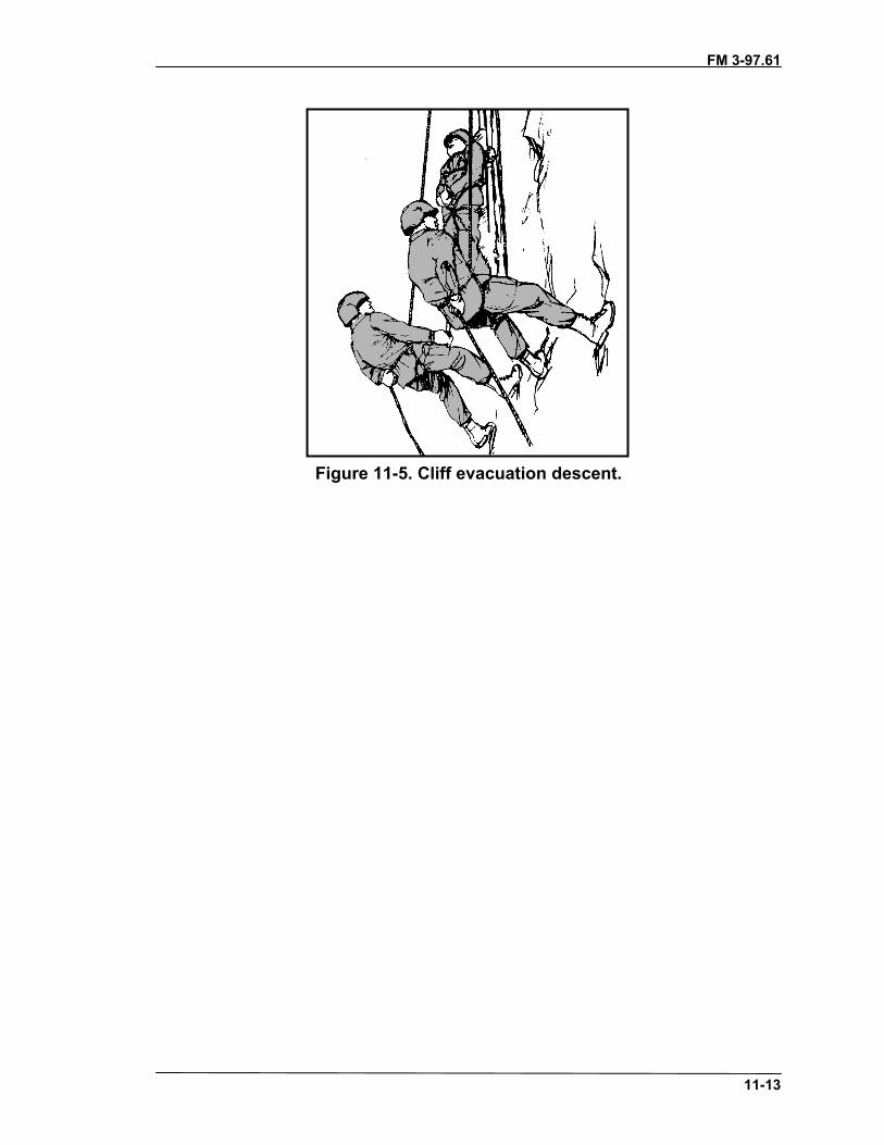
FM 3-97.61
11-13
Figure 11-5. Cliff evacuation descent.

FM 3-97.61(TC 90-6-1)
A-1
APPENDIX ALEVELS OF MILITARY MOUNTAINEERINGMilitary mountaineering training provides tactical mobility in
mountainous terrain that would otherwise be inaccessible. Soldiers withspecialized training who are skilled in using mountain climbing equipmentand techniques can overcome the difficulties of obstructing terrain. Highlymotivated soldiers who are in superior physical condition should beselected for move advanced military mountaineering training (Levels 2and 3) conducted at appropriate facilities. Soldiers who have completedadvanced mountaineering training should be used as trainers, guides, andlead climbers during collective training. They may also serve assupervisors of installation teams and evacuation teams. Properly usedthese soldiers can drastically improve mobility and have a positive impactdisproportionate to their numbers. Units anticipating mountain operationsshould strive to have approximately ten percent of their force achieveadvanced mountaineering skills.
A-1. LEVEL 1: BASIC MOUNTAINEERThe basic mountaineer should be a graduate of a basic mountaineering course and havethe fundamental travel and climbing skills necessary to move safely and efficiently inmountainous terrain. These soldiers should be comfortable functioning in thisenvironment and, under the supervision of qualified mountain leaders or assault climbers,can assist in the rigging and use of all basic rope installations.
a. On technically difficult terrain, the basic mountaineer should be capable ofperforming duties as the “follower” or “second” on a roped climbing team, and should bewell trained in using all basic rope systems. These soldiers may provide limitedassistance to soldiers unskilled in mountaineering techniques.
b. Particularly adept soldiers may be selected as members of special purpose teamsled and supervised by advanced mountaineers. Figure A-1 lists the minimum knowledgeand skills required of basic mountaineers.
c. In a unit training program, Level 1 qualified soldiers should be identified andprepared to serve as assistant instructors to train unqualified soldiers in basicmountaineering skills. All high-risk training, however, must be conducted under thesupervision of qualified Level 2 or 3 personnel.

FM 3-97.61
A-2
• Characteristics of the mountainenvironment (summer andwinter).
• Mountaineering safety.• Use, care, and packing of
individual cold weather clothingand equipment.
• Care and use of basicmountaineering equipment.
• Mountain bivouac techniques.• Mountain communications.• Mountain travel and walking
techniques.• Hazard recognition and route
selection.• Mountain navigation.• Basic medical evacuation.
• Rope management and knots.• Natural anchors.• Familiarization with artificial
anchors.• Belay and rappel techniques.• Use of fixed ropes (lines).• Rock climbing fundamentals.• Rope bridges and lowering
systems.• Individual movement on snow
and ice.• Mountain stream crossings (to
include water survivaltechniques).
• First aid for mountain illnessesand injuries.
Figure A-1. Level 1, basic mountaineering tasks.
A-2. LEVEL 2: ASSAULT CLIMBERAssault climbers are responsible for the rigging, inspection, use, and operation of allbasic rope systems. They are trained in additional rope management skills, knot tying,and belay and rappel techniques, as well as using specialized mountaineering equipment.Assault climbers are capable of rigging complex, multipoint anchors, and high-angleraising/lowering systems. Level 2 qualification is required to supervise all high-risktraining associated with Level 1. At a minimum, assault climbers should possess theadditional knowledge and skills shown in Figure A-2.
• Use specialized mountaineeringequipment.
• Perform multipitch climbing:_ Free climbing and aid
climbing._ Leading on class 4 and 5
terrain.• Conduct multipitch rappelling.• Establish and operate hauling
systems.• Establish fixed ropes with
intermediate anchors.
• Move on moderate angle snowand ice.
• Establish evacuation systems andperform high-angle rescue.
• Perform avalanche hazardevaluation and rescuetechniques.
• Be familiar with movement onglaciers.
Figure A-2. Level 2, assault climber tasks.
A-3. LEVEL 3: MOUNTAIN LEADERMountain leaders possess all the skills of the assault climber and have extensive practicalexperience in a variety of mountain environments in both winter and summer conditions.Level 3 mountaineers should have well-developed hazard evaluation and safe routefinding skills over all types of mountainous terrain. Mountain leaders are best qualified toadvise commanders on all aspects of mountain operations, particularly the preparationand leadership required to move units over technically difficult, hazardous, or exposed

FM 3-97.61
A-3
terrain. The mountain leader is the highest level of qualification and is the principletrainer for conducting mountain operations. Instructor experience at a militarymountaineering center or as a member of a special operations forces (SOF) mountainteam is critical to acquiring Level 3 qualification. Figure A-3 outlines the additionalknowledge and skills expected of mountain leaders. Depending on the specific AO,mountain leaders may need additional skills such as snowshoeing and all-terrain skiing.
• Recognizing and evaluatingpeculiar terrain, weather, andhazards.
• Preparing route, movement,bivouac, and risk managementplans for all conditions andelevation levels.
• Using roped movementtechniques on steep snow andice.
• Performing multipitch climbing onmixed terrain (rock, snow, andice).
• Performing glacier travel andcrevice rescue.
• Establishing and operatingtechnical high-angle, multipitchrescue and evacuation systems.
• Usiing winter shelters andsurvival techniques.
• Leading units over technicallydifficult, hazardous, or exposedterrain in both winter and summerconditions.
Figure A-3. Level 3, mountaineer leader tasks.

FM 3-97.61(TC 90-6-1)
B-1
APPENDIX BMEASUREMENT CONVERSION FACTORS
MULTIPLY BY TO OBTAIN
Millimeters .03937 Inches
Centimeters .3937 Inches
Centimeters .03281 Feet
Meters 39.37 Inches
Meters 3.281 Feet
Meters 1.0936 Yards
Kilometers .62137 Miles
Knots 1.1516 MPH
FM 3-97.61(TC 90-6-1)
C-1
APPENDIX CAVALANCHE SEARCH AND RESCUE TECHNIQUES
The effect of an avalanche can be disastrous. Chances of survival afterburial by an avalanche are approximately 90 percent if the victim islocated within the first 15 minutes. Probability of survival drops rapidlyand, after two hours, chances of survival are remote. Suffocation accountsfor 65 percent of avalanche fatalities, collision with obstacles such asrocks and trees accounts for 25 percent, and hypothermia and shockaccounts for 10 percent.
The best chance of survival in snow country is to avoid an avalanche;but, if a member of your group is in an avalanche, they are depending onyou for rescue!
C-1. IMMEDIATE ACTIONSurvivors at the avalanche site organize into the first rescue team and immediately startrescue operations. If any indication of the location of the victim is found, random probingstarts in that vicinity. The tip and edges of the slide are also likely areas to search. Ahuman body is bulky and is apt to be thrown toward the surface or the sides.
C-2. GENERAL PROCEDURESEstablish from witnesses where the victim was located just before the avalanche todetermine the point where the victim disappeared—the “last seen” point. Using this andany other information, establish a probable victim trajectory line leading to high prioritysearch areas. Make a quick but systematic check of the slide area and the deposition area,and mark all clues. Look for skis, poles, ice axes, packs, gloves, hats, goggles, boots, orany other article the person may have been carrying—it might still be attached to thevictim.
a. Organize initial searchers and probers. If using avalanche beacons, immediatelyselect personnel to begin a beacon search. Ensure all other beacons are turned off or toreceive to eliminate erroneous signals. All personnel should have a shovel or other toolfor digging or, if enough personnel are available, a digger can be standing by to assistwhen needed. If the initial search reveals items from the victim, make an initial probesearch in that area. This probing should take only a few seconds.
b. Make a coarse probe of all likely areas of burial, and repeat it as long as a liverescue remains possible. Resort to the fine probe only when the possibility of a liverescue is highly improbable. Unless otherwise indicated, start the coarse probe at thedeposition area.
C-3. ESTABLISHING THE VICTIM’S MOST PROBABLE LOCATIONIn many respects, a moving avalanche resembles a liquid. A human body, with a higherdensity than the flowing snow, would be expected to sink deeper and deeper into theavalanche; however, several factors influence the body’s location. Turbulence, terrain,and the victim’s own efforts to extricate himself all interact to determine the final burialposition. Study of a large number of case histories leads to the following conclusions.

FM 3-97.61
C-2
• The majority of buried victims are carried to the place of greatest deposition,usually the toe of the slide.
• If two points of the victim’s trajectory can be established, a high probabilityexists that the victim will be near the downhill flow line passing through thesetwo points.
• Any terrain features that catch and hold avalanche debris are also apt to catcha victim.
• If an avalanche follows a wandering gully, all debris deposit areas are likelyburial spots. The likelihood of a victim being buried in a particular bend isproportional to the amount of debris deposited there.
• Vegetation, rocks, and other obstacles act as snares. The victim tends to beretained above the obstacle. An obstacle may simply delay the victim’smotion, leading to final burial down flow from the obstacle.
• Maximum speed of the flowing snow occurs at the avalanche center. Frictionreduces flow velocity along the edges. The closer the victim’s trajectory is tothe center of the slide, the greater will be his burial depth.
• Efforts of the victim to extricate himself by vigorous motion and “swimming”definitely minimize burial depth. Conversely, the limp body of an unconsciousvictim is likely to be buried deeply.
• An occasional exception to the above is emphasized. The victim may not beburied but may have been hurled away from the avalanche by wind blast. Inthe case of large and violent avalanches, a search of the surrounding terrain isadvisable. Victims have been located in tree tops outside the slide area.
Use of avalanche transceivers is the most efficient method of searching for an avalanchevictim, but only if the victim is wearing an active transceiver. Many models oftransceivers are available, each with its own manufacturer’s instructions for proper useand care. All currently available transceivers are compatible, although they may operatedifferently in the search mode.
C-4. PROBING FOR AVALANCHE VICTIMSProbing offers the advantage of requiring simple equipment that can be operated bypersonnel with no previous training. Although the probers do not need previous trainingthe search leader must be familiar with the technique to ensure proper execution of theprobe line.
a. Probe Poles. Rigid steel tubing approximately 3/4-inch in diameter andapproximately 10 feet long is recommended for the primary probe pole. Longer poles aredifficult to manage, especially in a high wind. Although this type of pole performs best, itis difficult to transport to the avalanche site because of its length and weight.
(1) Each person operating in avalanche areas should carry folding sectional poles.These poles are similar to folding tent poles, but are stronger and are connected withcable instead of bungee cord. These poles should be carried on the outside of the pack forimmediate access.
(2) If no probing poles are available, initial probing attempts can be started using skipoles in one of two ways: the ski pole can be reversed, probing with the wrist strap down;or the basket can be removed so that the point is down (the preferred method), whichallows the ski pole to penetrate the snow more easily.

FM 3-97.61
C-3
b. Probing Lines. For the probing operation to be effective, probing lines must beorderly and properly spaced. To ensure systematic and orderly probing, the number ofpersonnel per line should be limited. Twenty per line is satisfactory, while thirty isnormally the upper limit. The number of probers in the line will be dictated by not onlythe width of the area to be probed but the number of personnel available. A string may beused to keep the probe lines aligned, but will require added time to maintain.
(1) The probe line maintains a steady advance upslope. Advancing uphillautomatically helps set the pace and permits easy probing to the full length of the probe.Probing does not come to a halt when a possible contact is made. The probe is left incontact and the line continues. A shovel crew follows up on the strike by digging downalong the pole. Extra probes are carried by the shovel crew to replace those left incontact. Such a plan of operation is especially important when more than one victim isburied.
(2) Striking a body gives a distinct feel to the probe, which is easily recognizable insoft snow but less recognizable in hard compacted snow. A common problem isencountering debris within the snow that can be mistaken for the victim. The only surecheck is by digging.
c. Probing Techniques. Two distinct probing methods are recognized: coarse probeand fine probe. As evidenced by their names, coarse probing implies a wider spacing ofprobe pole insertions with emphasis on speed. Fine probing involves close-spacedprobing with emphasis on thoroughness. Coarse probing is used during initial phases ofthe search when live recovery is anticipated. Fine probing is the concluding measure,which almost guarantees finding the body. The coarse probe technique has a 70-percentchance of locating the victim on a given pass, while the fine probe has, essentially, a100-percent chance of locating the body.
(1) The coarse probe functions as follows: (a) Probers are spaced along a line 30 inches center to center, with feet about 15
inches apart.(b) A single probe pole insertion is made at the center of the straddle span.(c) On command of the probe line commander, the group advances 20 inches and
repeats the single probe.(d) Three commands are used for the complete sequence:
• “DOWN PROBE.”• “UP PROBE.”• “STEP FORWARD.”
By using these commands, the leader can maintain closer control of the advancing probeline. It is important that the commands be adjusted to a rhythm that enforces themaximum reasonable pace. A string may also be used along the probe line to keep theprobers dressed, although this requires the use of two soldiers to control the string. Strictdiscipline and firm, clear commands are essential for efficient probing. The probersthemselves work silently.
(2) The fine probe functions as follows:(a) Probers are spaced the same as for the coarse probe. Each man probes in front of
his left foot, then in the center of his straddled position, and finally in front of his rightfoot.
FM 3-97.61
C-4
(b) On command, the line advances 1 foot and repeats the probing sequence. Eachprobe is made 10 inches from the adjacent one.
(c) The commands for the fine probe are:• “LEFT PROBE.”• “UP PROBE.”• “CENTER PROBE.”• “UP PROBE.”• “RIGHT PROBE.”• “UP PROBE.”• “STEP FORWARD.”
(d) Good discipline and coordinated probing is even more important in fine probingthan with the coarse probe. Careless or irregular probing can negate the advantages offine probing. Use of a string to align the probers is especially important with the fineprobe. The three insertions are made along the line established by the string, which isthen moved ahead 1 foot.

FM 3-97.61(TC 90-6-1)
Glossary-1
GLOSSARY
AI alpine iceALICE all-purpose, lightweight, individual carrying equipmentAMS acute mountain sicknessAPS anchor pulley systemATC air traffic controller
BDU battle dress uniformBTC bridge team commander
C CelsiusCE community EuropeCEN combined European normcm centimeterCMS chronic mountain sicknessCPR cardio-pulmonary resuscitationCTA common table of allowance
DA Department of the Army
ECWCS extreme cold weather clothing systemEN European norm
F FahrenheitFM field manualft foot; feet
GPS Global Positioning SystemGTA graphic training aid
HACE high-altitude cerebral edemaHAPE high-altitude pulmonary edema
IAW in accordance with
LBV load-bearing vestLCD liquid crystal diodeLCE load-carrying equipment
MEDEVAC medical evacuationMPH miles per hourMPS moveable pulley systemMRE meal ready-to-eat

FM 3-97.61
Glossary-2
NSN national stock number
OP observation post
PABA para-amino benzoic acidPCD progress capture devicePFD personal flotation device
RURP realized ultimate reality piton
SE southeastSLCD spring-loaded camming deviceSOF special operations forcesSOP standard operating procedureSOSES shape, orientation, size, elevation, slopeSPF sun protection factor
TOE table of organization and equipment
UIAA Union des International Alpine AssociationU.S. United StatesUSAF United States Air ForceUSN United States NavyUV ultravioletUVA ultraviolet A (radiation wavelengths between 320 and 400 nanometers)UVB ultraviolet B (radiation wavelengths between 295 and 320 nanometers)
WI waterfall ice
YDS Yosemite Decimal System

FM 3-97.61(TC 90-6-1)
References-1
REFERENCES
Documents Needed
These documents must be available to the intended users of this manual.
FM 3-25.26 Map Reading and Land Navigation. 20 July 2001.
*FM 3-97.6 Mountain Operations. 28 November 2000.
FM 8-10-6 Medical Evacuation in a Theater of Operations Tactics,Techniques, and Procedures. 14 April 2000.
FM 21-76 Survival. 05 June 1992.
DA Form 2028 Recommended Changes to Publications and Blank Forms.01 February 1974.
DA Form 5752-R Rope History and Usage. May 1989.
CTA 50-900 Clothing and Individual Equipment. 01 September 1994.
GTA 05-08-012 Individual Safety Card. 25 February 1999.
STP 21-1-SMCT Soldier’s Manual of Common Tasks, Skill Level 1.01 October 2001.
STP 21-24-SMCT Soldier’s Manual of Common Tasks, Skill Levels 2—4.01 October 2001.
USAF TO 00-75-5 Use, Inspection and Maintenance Stokes Rescue Litters.01 April 1979.
Readings Recommended
These readings contain relevant supplemental information.
Mountaineering: Freedom of the Hills, 6th edition, The Mountaineers, Seattle, WA, 1997
Soles, Clyde, Rock and Ice Gear: Equipment for the Vertical World, The Mountaineers,Seattle, WA, 2000
*This source was also used to develop the manual.

FM 3-97.61
References-2
Internet Web Sites
U.S. Army Publishing Agencyhttp://www.usapa.army.mil
Army Doctrine and Training Digital Libraryhttp://www.adtdl.army.mil

FM 3-97.61(TC 90-6-1)
Index-1
INDEXacute mountain sickness, 2-6, 2-8, 2-21anchors, 5-1 to 5-16
artificial, 5-8 to 5-15bolts, 5-14, 5-16 (illus)chocks, 5-11
placement, 5-12, 5-13 (illus)deadman, 5-8pitons, 5-9
hero loop, 5-10 (illus)placement, 5-9, 5-10 (illus)removal, 5-11 (illus)reusing, 5-11
spring-loaded camming device, 5-13,5-14 (illus)
natural, 5-1boulders, 5-2 (illus)bushes and shrubs, 5-4 (illus)chockstones, 5-2, 5-3 (illus)rock projections, 5-3 (illus)slinging techniques, 5-4 thru 5-6trees, 5-1 (illus)tunnels and arches, 5-4
pre-equalized, 5-16 (illus)rope, 5-7 (illus)
tensionless, 5-7, 5-8 (illus)self-equalizing, 5-15 (illus)
ascenders, 3-20 (illus)avalanche, 1-27
hazards, 1-29checklist, 1-32 (table)slope stability, 1-29snow pits, 1-30triggers, 1-29
rescue equipment, 3-27 (illus)avalanche probe, 3-27, C-2avalanche transceivers, C-27search and rescue techniques, C-1
belay devices, 3-19 (illus)bolts, 3-18, 3-19 (illus), 5-14, 6-54
carabiners, 3-11, 3-12 (illus)chock picks, 3-18 (illus)chocks, 3-15 (illus), 6-55
climbing, 6-1aid, 6-54combination techniques, 6-19
change step, 6-19chimney sequence, 6-24, 6-25 (illus)down climbing, 6-25lieback, 6-21, 6-22 (illus)mantling, 6-19, 6-20 (illus)stemming, 6-22 (illus)undercling, 6-20, 6-21 (illus)
commands, 6-43rope tug, 6-44verbal, 6-43, 6-44 (table)
lead, 6-45roped, 6-27
belay techniques, 6-32body belay, 6-34
sitting, 6-36 (illus)standing, 6-36 (illus)
mechanical, 6-37tying-in, 6-27, 6-29 (illus)
safety, 6-8 thru 6-9sequence, 6-4 thru 6-8 (illus)shoes, 3-2 (illus)stance, 6-3
correct, 6-3 (illus)incorrect, 6-4 (illus)
top-roped, 6-45using the hands, 6-13
jam hold, 6-17, 6-18 (illus)pinch hold, 6-16, 6-17 (illus)pull hold, 6-15, 6-16 (illus)push hold, 6-14, 6-15 (illus)
using the feet, 6-10edging, 6-11, 6-12 (illus)jamming, 6-12, 6-13 (illus)smearing, 6-12 (illus)sole contact, 6-10, 6-11 (illus)
clothing, 3-2eyewear, 3-7 (illus)gaiters, 3-4, 3-5 (illus)hand wear, 3-5, 3-6 (illus)headwear, 3-6 (illus)helmets, 3-7 (illus)

FM 3-97.61
Index-2
insulating layers, 3-3, 3-4 (illus)outer layers, 3-3socks, 3-2underwear, 3-2
clouds, 1-15 to 1-23cover, 1-25formation, 1-15interpretation, 1-23types, 1-15
altocumulus, 1-18 (illus)altostratus, 1-18 (illus)cirrostratus, 1-19, 1-20 (illus)cirrus, 1-19 (illus)contrails, 1-22 (illus)cumulonimbus, 1-20, f1-21 (illus)cumulus, 1-15, 1-16 (illus), 1-20lenticular, 1-21, 1-22 (illus)nimbostratus, 1-15, 1-17 (illus)orographic, 1-21stratocumulus, 1-15, 1-17 (illus)stratus, 1-15, 1-16 (illus)
cord, 3-9crampons, 3-22, 3-23 (illus), 10-2, 10-8
walking in, 10-6 (illus)use of, 10-2
crevasse, 10-27bivouac procedures, 10-33rescue techniques, 10-29snow bridge, 10-27
dehydration, 2-14descenders, 3-20 (illus)
frostbite, 2-11, 2-18 (illus), 2-19 (illus)
gear, 3-30 thru 3-33personal, 3-30specialized, 3-31standard, 3-30ten essentials, 3-32, 3-33
glacier, 10-19 (illus), 10-22 (illus)ablation zone, 10-23 (illus)
harness, 3-10chest, 3-10, 6-28full-body, 3-10, 6-28
improvised, 6-28, 6-29, 6-30 (illus)bowline-on-a-coil, 6-28swami belt, 6-28
seat, 3-10, 3-11 (illus), 6-27headlamps, 3-30heat cramps, 2-20heat exhaustion, 2-21heat stroke, 2-21Hibler Pack, 2-17high-altitude cerebral edema, 2-6, 2-22,
2-24, 2-25high-altitude pulmonary edema, 2-6,
2-23, 2-25hypothermia, 2-15
ice ax, 3-21, 3-22 (illus), 10-2, 10-7,10-9use of, 10-2
anchor position, 10-4 (illus)cane position, 10-2, 10-3 (illus)cross body position, 10-3 (illus)dagger position, 10-5 (illus)hammer position, 10-5, 10-6 (illus)push-hold position, 10-4, 10-5 (illus)
ice hammer, 3-22 (illus)ice screws, 3-24 (illus), 10-15 (illus)
Kernmantle, 3-8 (illus)knots, 4-8 to 4-33
Bachman, 4-23, 4-24 (illus)bowline, 4-13, 4-14 (illus)bowline-on-a-bight, 4-19, 4-20 (illus)bowline-on-a-coil, 4-24, 4-25 (illus)classes of, 4-8clove hitch, 4-16, 4-17 (illus)directional figure-eight, 4-18, 4-19(illus)double fisherman’s, 4-10, 4-11 (illus)end-of-the-rope Prusik, 4-22, 4-23(illus)figure-eight bend, 4-11, 4-12 (illus)figure-eight loop, 4-21 (illus)figure-eight retrace, 4-15, 4-16 (illus)figure-eight slip, 4-26, 4-27 (illus)fisherman’s, 4-9, 4-10 (illus)frost, 4-29 (illus)

FM 3-97.61
Index-3
girth hitch, 4-30 (illus)guarde, 4-32, 4-33 (illus)Kleimheist, 4-28 (illus)middle-of-the-rope Prusik, 4-22 (illus)munter hitch, 4-30, 4-31 (illus)rappel seat, 4-31, 4-32 (illus)round turn and two half hitches, 4-14,4-15 (illus)square, 4-9 (illus)transport, 4-27 (illus)three-loop bowline, 4-25, 4-26 (illus)two-loop figure-eight, 4-20, 4-21(illus)water, 4-12, 4-13 (illus)wireman’s, 4-17, 4-18 (illus)
litters, 11-7basket type, 11-7field-expedient, 11-8patient rescue and recovery system,11-8 (illus)poleless, nonrigid, 11-7poleless, semi-rigid, 11-7standard collapsible, 11-7Stokes metal, 11-7UT 2000, 11-8
mountain, 1-1building, 1-4composition, 1-1structure, 1-4
complex, 1-5dome, 1-4fault-block, 1-4fold, 1-5volcanic, 1-6
rescue and evacuation, 11-1stream crossing, 9-1
individual, 9-3, 9-4 (illus)site selection, 9-1 (illus)team, 9-4, 9-5 (illus)
walking techniques, 8-1mountaineering boots, 3-2 (illus)
nutrition, 2-2carbohydrates, 2-3
fats, 2-3minerals, 2-4protein, 2-3vitamins, 2-3
one-rope bridge, 7-14commando crawl, 7-19 (illus)hauling line, 7-21 (illus)monkey crawl, 7-19, 7-20 (illus)transport knot, 7-16 (illus)transport tightening system, 7-15Z-pulley tightening system, 7-18 (illus)
packs, 3-27day, 3-31safety, 3-31
personal hygiene, 2-5pitons, 3-13, 3-14 (illus), 6-54
ice, 3-24, 3-25 (illus), 10-14piton hammer, 3-14 (illus)pulleys, 3-21 (illus)
rappelling, 7-5commands, 7-7 (table)types, 7-9
body, 7-10 (illus)hasty, 7-9 (illus)seat-hip, 7-10, 7-11 (illus)
rating system, 1-8 (table)rocks, 1-1
classifications, 1-2igneous, 1-2metamorphic, 1-3sedimentary, 1-3
types, 1-1chalk and limestone, 1-2granite, 1-1sandstone, 1-2slate and gneiss, 1-2scree, 1-2talus, 1-2
rope coil carry, 11-5ropes, 3-8, 4-1
butterfly coil, 4-6 (illus), 4-7 (illus)dynamic, 3-8

FM 3-97.61
Index-4
fixed, 7-1installation, 7-1retrieval, 7-2utilization, 7-1, 7-2 (illus)
mountain coil, 4-4, 4-5 (illus)mountaineering, 4-1 to 4-3 (illus)static, 3-8terminology, 4-3, 4-4 (illus)
route rating, 1-6 to 1-8
sanitation, 2-6self-arrest, 10-11 (illus)shock, 2-14sleds, 3-29sling-rope carry, 11-4, 11-5 (illus)ski poles, 3-29 (illus)skis, 3-28snowblindness, 2-10snow picket, 3-25, 3-26 (illus)snow saw, 3-26snowshoes, 3-29snow shovel, 3-26spring-loaded camming device, 3-17
(illus), 5-13, 6-55stoves, 3-28sunburn, 2-10suspension traverse, 7-22 (illus)
construction, 7-23, 7-24 (illus)equipment, 7-23
tents, 3-28three-point camming device, 3-16 (illus)trench foot, 2-17
Union des International AlpineAssociation, 1-7, 3-8
vertical hauling line, 7-27 (illus)
wands, 3-27water, 2-1, 2-2
consumption, 2-1, 2-2potable, 2-2
weather, 1-11characteristics, 1-12
high pressure, 1-12
low pressure, 1-13forecasting methods, 1-24, 1-25
analog, 1-25climatology, 1-25numerical weather prediction, 1-25persistence, 1-24trends, 1-25
fronts, 1-23cold, 1-23occluded, 1-23stationary, 1-23warm, 1-23
hazards, 1-28humidity, 1-14temperature, 1-23, 1-26
webbing, 3-9tied runners, 3-9 (illus)sewn runners, 3-9 (illus)
wind, 1-13air masses, 1-14anabatic, 1-14chill, 2-11, 2-12 (illus)direction, 1-25katabatic, 1-14northeast tradewinds, 1-14prevailing westerlies, 1-13speed, 1-25
wired snow anchors, 3-25, 3-26 (illus)
Yosemite Decimal System, 1-6


FM 3-97.61 (TC 90-6-1)26 AUGUST 2002
By Order of the Secretary of the Army:
ERIC K. SHINSEKI General, United States Army
Chief of Staff
Official:
JOEL B. HUDSON Administrative Assistant to the
Secretary of the Army 0220602
DISTRIBUTION:
Active Army, Army National Guard, and US Army Reserve: To be distributed in accordance with the initialdistribution number 111444, requirements for FM 3-97.61.

PIN: 080110-000


![Basic Mountaineering Course Student Handbookbe Mountaineers Basic Mountaineering Course Manual [3] Introduction Welcome to the Basic Mountaineering Course. We look forward to working with you, to](https://static.documents.pub/doc/80x56/5aaf77a27f8b9aa8438d56db/basic-mountaineering-course-student-handbookbe-mountaineers-basic-mountaineering.jpg)