17
Mill Creek Resiliency Building Greenhouse Gas Impacts of building materials and operation Summary report for Executive Order 17-20 August 2021

Mill Creek
Resiliency Building Greenhouse Gas Impacts of building materials and operation
Summary report for Executive Order 17-20
August 2021

This document was prepared by The Oregon Department of Environmental Quality
Materials Management Program 700 NE Multnomah Street, Suite 600
Portland Oregon, 97232 Contact: Jordan Palmeri Phone: 503-229-6766 www.oregon.gov/deq
With support from a project team*, consisting of: Owner: PJS Land Development
Developer: RPS Development Company, Inc. Tenant: Oregon State Treasury Tenant Representative: Klosh Group Contractor: Pence Construction Architect: GBD Architects Inc. Structural Engineer: KPFF Consulting Engineers MEP and LV Engineer: Glumac Tenant Technical Consultant: WSP USA
DEQ can provide documents in an alternate format or in a language other than English upon
request. Call DEQ at 800-452-4011 or email [email protected].
*Oregon Department of Environmental Quality does not endorse any particular product or company

Case Study: Mill Creek Resiliency Building
3
Introduction
Construction for an earthquake-resilient 35,000 square foot building is underway in Salem, Oregon, to house the Oregon State Treasury (OST). OST signed a long-term lease for the building, which is designed to keep the agency operational to meet the state’s financial needs after a major catastrophe. Although this is not a State-owned building, the project team pursued greenhouse gas (GHG) reduction opportunities in both building operation and selection of construction materials, consistent with Executive Order 17-20 for newly constructed state buildings. This summary report focuses on the material-related GHG impacts, also known as “embodied carbon.” Embodied carbon is the greenhouse gas emissions resulting from the raw material extraction, transportation, and manufacturing of building materials.
Key building features, include:
Seismic base isolation and other structural features to help make the building usable immediately after a 9.0 earthquake
Net zero energy design – conservation and efficiency measures to reduce overall electric load On-site solar energy production with back-up emergency power Emergency water and septic systems and water conservation features Advanced ventilation and air filtration features Data and telecommunications redundancies to support connectivity after a catastrophic event
Rendering provided by GBD Architects
Case Study: Mill Creek Resiliency Building
4
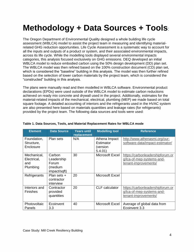
Methodology + Data Sources + Tools: The Oregon Department of Environmental Quality designed a whole building life cycle assessment (WBLCA) model to assist the project team in measuring and identifying material-related GHG reduction opportunities. Life Cycle Assessment is a systematic way to account for all the inputs and outputs of a product or system, and their associated environmental impacts, across its life cycle. While the modelling tools displayed several environmental impacts categories, this analysis focused exclusively on GHG emissions. DEQ developed an initial WBLCA model to reduce embodied carbon using the 50% design development (DD) plan set. The WBLCA model was then refined based on the 100% construction document (CD) plan set, which is considered the “baseline” building in this analysis. The model was then further refined based on the selection of lower carbon materials by the project team, which is considered the “constructed” building in this analysis. The plans were manually read and then modelled in WBLCA software. Environmental product declarations (EPDs) were used outside of the WBLCA model to estimate carbon reductions achieved on ready mix concrete and drywall used in the project. Additionally, estimates for the material-related impacts of the mechanical, electrical, plumbing (MEP) we made based on total square footage. A detailed accounting of interiors and the refrigerants used in the HVAC system are also presented here based on materials quantities and leakage rates (for refrigerants) provided by the project team. The following data sources and tools were used: Table 1. Data Sources, Tools, and Material Replacement Rates for WBLCA mode
Element Data Source Years until replacement
Modelling tool Reference
Foundation, Structure, Enclosure
Plan sets N/A Athena Impact Estimator (version 5.4.01)
http://www.athenasmi.org/our-software-data/impact-estimator/
Mechanical, Electrical, and Plumbing
Carbon Leadership Forum (medium impact/sqft)
30 Microsoft Excel https://carbonleadershipforum.org/lca-of-mep-systems-and-tenant-improvements/
Refrigerants Plan sets + contractor interview
20 Microsoft Excel
Interiors and Finishes
Contractor provided quantities
20 CLF calculator https://carbonleadershipforum.org/lca-of-mep-systems-and-tenant-improvements/
Photovoltaic Panels
Ecoinvent 3.3
40 Microsoft Excel Average of global data from Ecoinvent 3.3
Case Study: Mill Creek Resiliency Building
5
Results + Discussion:
Constructed Building
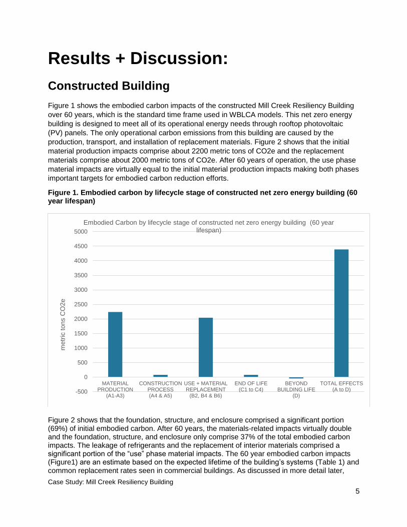
Figure 1 shows the embodied carbon impacts of the constructed Mill Creek Resiliency Building
over 60 years, which is the standard time frame used in WBLCA models. This net zero energy
building is designed to meet all of its operational energy needs through rooftop photovoltaic
(PV) panels. The only operational carbon emissions from this building are caused by the
production, transport, and installation of replacement materials. Figure 2 shows that the initial
material production impacts comprise about 2200 metric tons of CO2e and the replacement
materials comprise about 2000 metric tons of CO2e. After 60 years of operation, the use phase
material impacts are virtually equal to the initial material production impacts making both phases
important targets for embodied carbon reduction efforts.
Figure 1. Embodied carbon by lifecycle stage of constructed net zero energy building (60 year lifespan)
Figure 2 shows that the foundation, structure, and enclosure comprised a significant portion (69%) of initial embodied carbon. After 60 years, the materials-related impacts virtually double and the foundation, structure, and enclosure only comprise 37% of the total embodied carbon impacts. The leakage of refrigerants and the replacement of interior materials comprised a significant portion of the “use” phase material impacts. The 60 year embodied carbon impacts (Figure1) are an estimate based on the expected lifetime of the building’s systems (Table 1) and common replacement rates seen in commercial buildings. As discussed in more detail later,
-500
0
500
1000
1500
2000
2500
3000
3500
4000
4500
5000
MATERIALPRODUCTION
(A1-A3)
CONSTRUCTIONPROCESS(A4 & A5)
USE + MATERIALREPLACEMENT
(B2, B4 & B6)
END OF LIFE(C1 to C4)
BEYONDBUILDING LIFE
(D)
TOTAL EFFECTS(A to D)
metr
ic tons C
O2e
Embodied Carbon by lifecycle stage of constructed net zero energy building (60 year lifespan)

Case Study: Mill Creek Resiliency Building
6
there are opportunities to reduce the potential impacts of the refrigerants and interiors over the building’s lifetime. Figure 2. Materials-related embodied carbon impacts during the initial material production phase and after 60 years of operation.
Table 2. Metric tons of CO2e for initial material production versus 60 year carbon impacts
Initial 60 year
Foundation, Structure, Enclosure 1555 1555
Mechanical, Electrical, Plumbing (MEP) 195 585
Refrigerants 2.3 846
Interiors (finishes and furniture) 247 740
PV (photovoltaic panels) 239 478
TOTAL 2238 4204
0
500
1000
1500
2000
2500
3000
3500
4000
4500
Initial 60 year
met
ric
ton
s C
O2
e
Initial vs 60 year embodied carbon contributions
Foundation, Structure, Enclosure MEP Refrigerants Interiors PV
Case Study: Mill Creek Resiliency Building
7
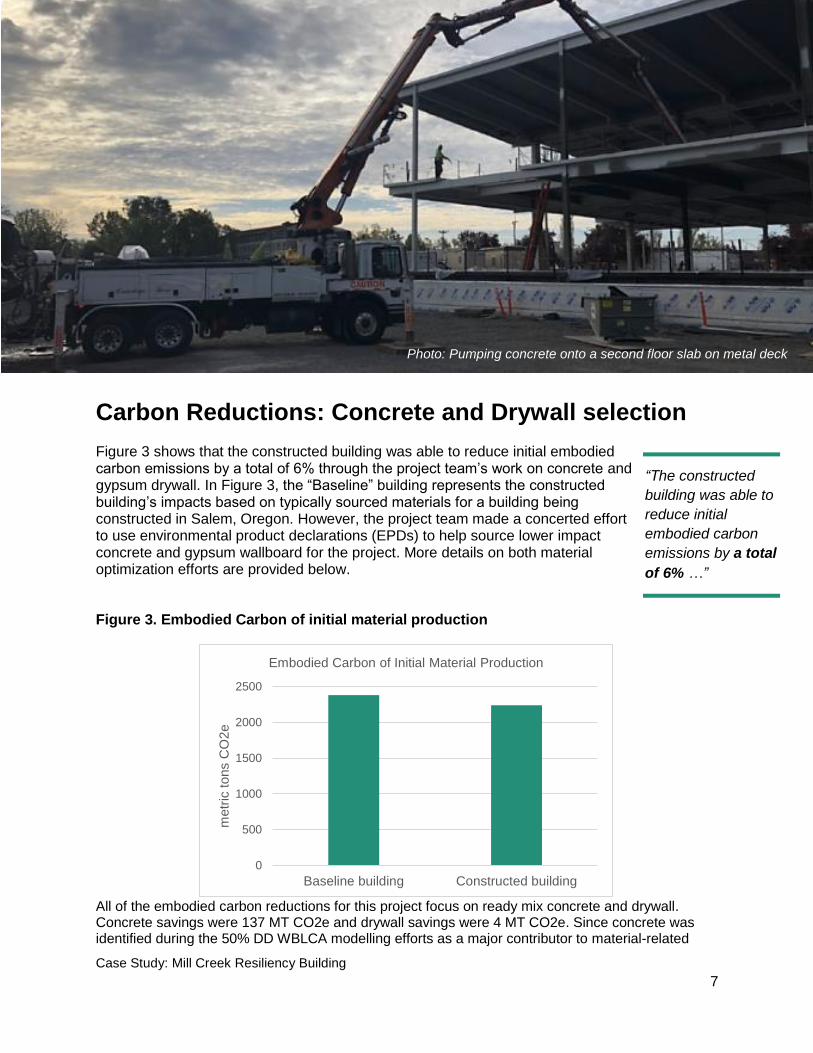
Carbon Reductions: Concrete and Drywall selection
Figure 3 shows that the constructed building was able to reduce initial embodied carbon emissions by a total of 6% through the project team’s work on concrete and gypsum drywall. In Figure 3, the “Baseline” building represents the constructed building’s impacts based on typically sourced materials for a building being constructed in Salem, Oregon. However, the project team made a concerted effort to use environmental product declarations (EPDs) to help source lower impact concrete and gypsum wallboard for the project. More details on both material optimization efforts are provided below. Figure 3. Embodied Carbon of initial material production
All of the embodied carbon reductions for this project focus on ready mix concrete and drywall. Concrete savings were 137 MT CO2e and drywall savings were 4 MT CO2e. Since concrete was identified during the 50% DD WBLCA modelling efforts as a major contributor to material-related
0
500
1000
1500
2000
2500
Baseline building Constructed building
metr
ic tons C
O2e
Embodied Carbon of Initial Material Production
Photo: Pumping concrete onto a second floor slab on metal deck
“The constructed
building was able to
reduce initial
embodied carbon
emissions by a total
of 6% …”
Case Study: Mill Creek Resiliency Building
8
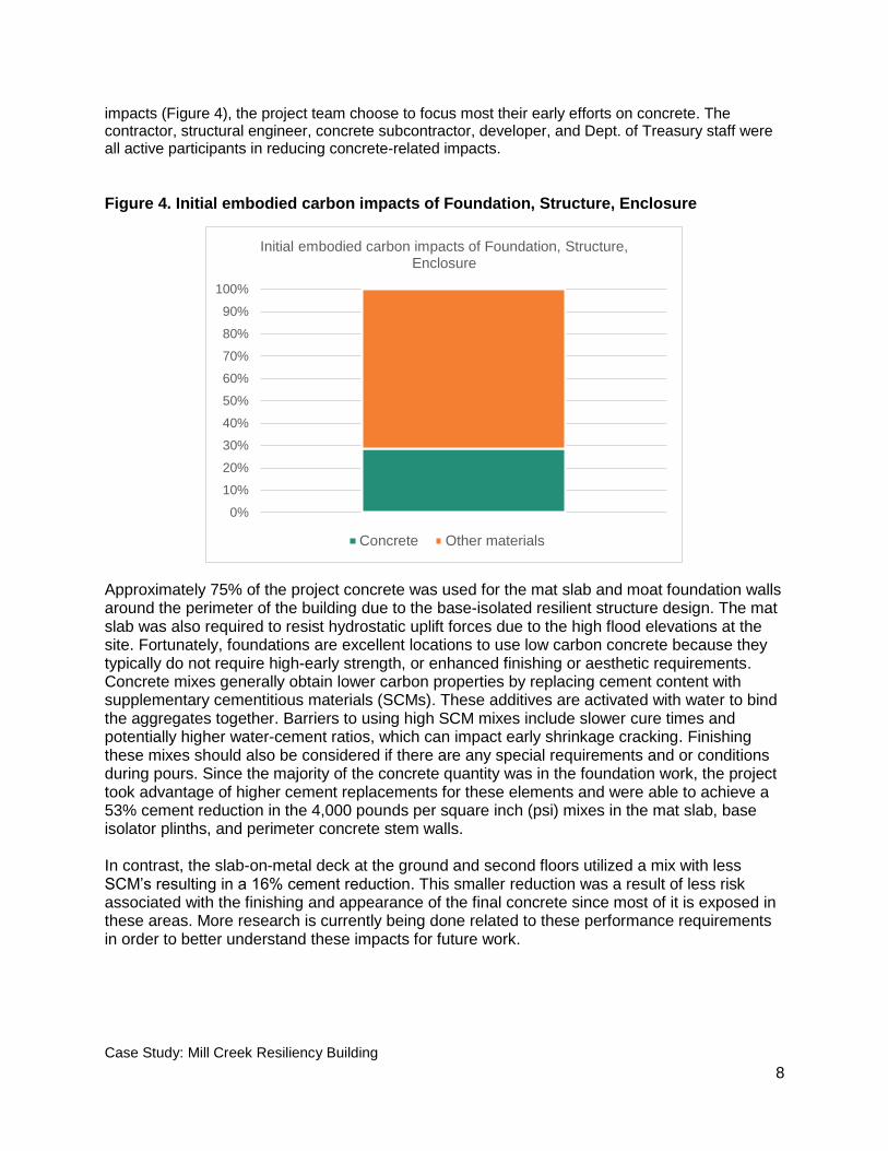
impacts (Figure 4), the project team choose to focus most their early efforts on concrete. The contractor, structural engineer, concrete subcontractor, developer, and Dept. of Treasury staff were all active participants in reducing concrete-related impacts.
Figure 4. Initial embodied carbon impacts of Foundation, Structure, Enclosure
Approximately 75% of the project concrete was used for the mat slab and moat foundation walls around the perimeter of the building due to the base-isolated resilient structure design. The mat slab was also required to resist hydrostatic uplift forces due to the high flood elevations at the site. Fortunately, foundations are excellent locations to use low carbon concrete because they typically do not require high-early strength, or enhanced finishing or aesthetic requirements. Concrete mixes generally obtain lower carbon properties by replacing cement content with supplementary cementitious materials (SCMs). These additives are activated with water to bind the aggregates together. Barriers to using high SCM mixes include slower cure times and potentially higher water-cement ratios, which can impact early shrinkage cracking. Finishing these mixes should also be considered if there are any special requirements and or conditions during pours. Since the majority of the concrete quantity was in the foundation work, the project took advantage of higher cement replacements for these elements and were able to achieve a 53% cement reduction in the 4,000 pounds per square inch (psi) mixes in the mat slab, base isolator plinths, and perimeter concrete stem walls. In contrast, the slab-on-metal deck at the ground and second floors utilized a mix with less SCM’s resulting in a 16% cement reduction. This smaller reduction was a result of less risk associated with the finishing and appearance of the final concrete since most of it is exposed in these areas. More research is currently being done related to these performance requirements in order to better understand these impacts for future work.
0%
10%
20%
30%
40%
50%
60%
70%
80%
90%
100%
Initial embodied carbon impacts of Foundation, Structure, Enclosure
Concrete Other materials

Case Study: Mill Creek Resiliency Building
9
Using a project average approach to the carbon reduction allowed the team to vary the SCM’s for the different concrete uses to achieve an overall cement reduction of 38% and carbon reduction of 24%. In this project, ground granulated blast furnace steel slag was used as the supplementary cementitious material (SCM). Steel slag is typically used as an SCM in Oregon since the supply of coal fly ash (another common SCM) is decreasing as coal fired power plants are phased out. The concrete producer, Wilsonville Concrete Products, also used Type 1L cement (Portland Limestone Cement), which typically has a lower carbon footprint than most Type 1/2 cements. Overall, Figure 5 shows that the contractor (Pence Construction), structural engineer (KPFF), and concrete producer (Wilsonville concrete) were able to coordinate to reduce total impacts of concrete by 24%, which is an impressive reduction of carbon impacts.
Figure 5. Embodied carbon of typical versus project selected concrete mixes
The gypsum drywall specified in this project was originally a standard 5/8” Type X drywall from USG. After reviewing EPDs, the project team decided to purchase the USG EcoSmart 5/8” Type X gypsum product, which has 14% fewer embodied carbon emissions than the originally specified product. This lighter weight gypsum does reduce the sound transmission class (STC) rating of the wall assembly by approximately 1%. However, the project team found the minor 1% reduction acceptable in exchange for more carbon savings. Additionally, the team was already framing the interior walls at 24” on center versus the more standard 16 inches on center. Generally, the 24 inch stud spacing reduces embodied carbon, sound transmission, and heat exchange for interior wall assemblies.
0
100
200
300
400
500
600
700
Typical concrete mixes Project concrete mixes
metr
ic tons C
O2e
Embodied carbon of typical versus project selected concrete mixes
Using a project
average approach to
the carbon reduction
allowed the team to
vary the SCM’s for the
different concrete
uses to achieve an
overall cement
reduction of 38% and
carbon reduction of
24%.
Case Study: Mill Creek Resiliency Building
10
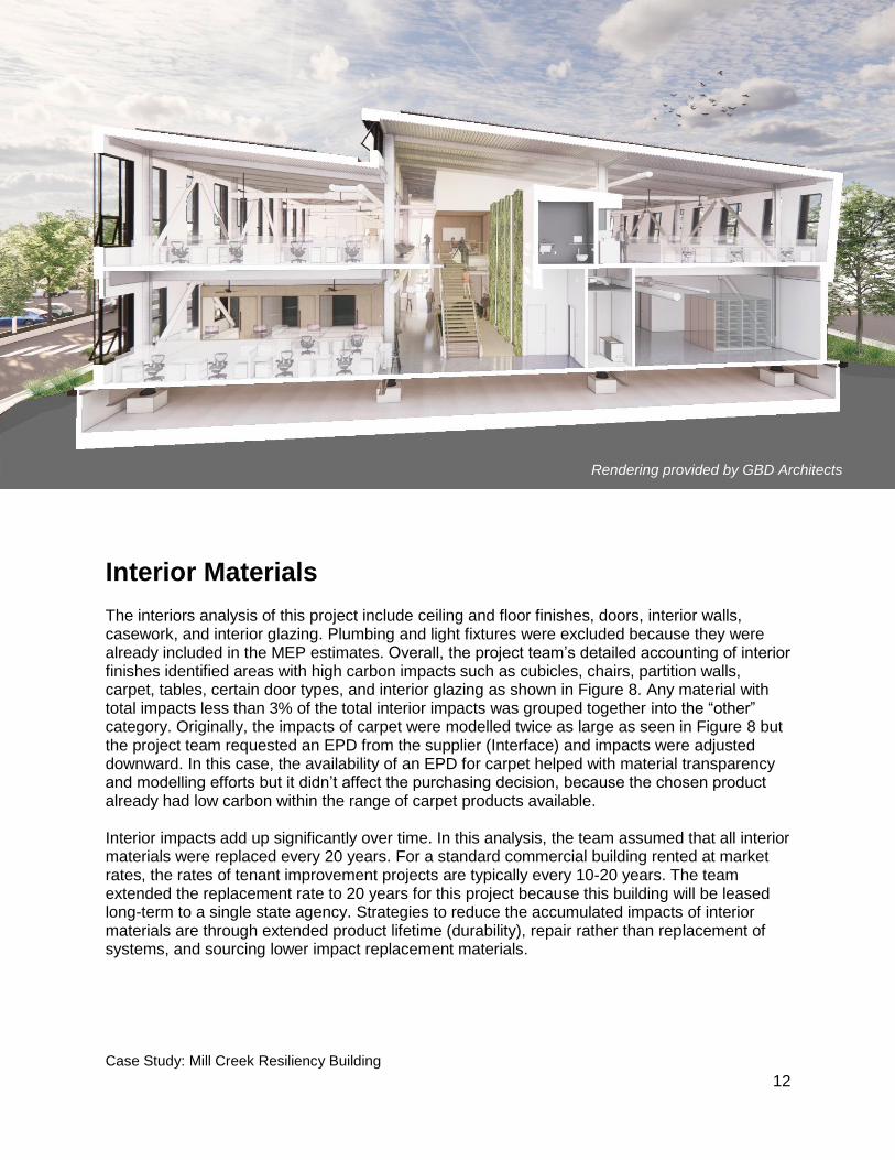
Figure 6. Gypsum drywall embodied carbon impacts of baseline vs constructed
Refrigerants in the HVAC system
The impacts of the R410a refrigerant used in the HVAC system have the potential to add up significantly over time as shown in Figure 2 above. R410a is scheduled to be phased out from use starting in 2024 and has a global warming potential (GWP) of 2088, compared to the GWP of CO2 of 1. Leaks through faulty field joints, during service visits, and at end-of-life recovery of the refrigerants are the most common forms of leakage. The contractor estimated 2% annual leakage and 1% leakage during service. End of life leakage was assumed to be 15% based on common industry estimates.
0
5
10
15
20
25
30
35
Baseline Type X Constructed Type X
metr
ic tons C
O2e
Gypsum drywall embodied carbon impacts of baseline vs constructed

Case Study: Mill Creek Resiliency Building
11
During construction, the copper piping system is pressurized and tested for leaks prior to putting the refrigerant in. However, annual leaks can happen due to expansion and contraction of pipes and the accidental bump of a pipe, which can loosen the joint. Fortunately, the variable refrigerant flow (VRF) systems used in this building will not operate if they are running low on refrigerant. System notifications would quickly indicate large leaks in the system. Overall, opportunities to reduce the refrigerant impacts include regular inspection, maintenance, leak detection, and replacement with a compatible lower GWP refrigerant when available. Clearly, an all-electric building constructed to operate as “net zero” due to rooftop PV can have operational impacts from leaking refrigerants. Future projects should consider initially sourcing a lower GWP refrigerant since R410a is still a very high impact product. Any choice of refrigerant needs to be carefully balanced with the overall efficiency of the system it serves to take a full lifecycle perspective into account. Figure 7 below shows that the embodied carbon impacts of refrigerant production is minor in comparison to the carbon impacts of potential leakage, which reinforces that initial choice of refrigerant type and maintenance and leak control over operation are critical for this building system.
Figure 7. Impacts of Refrigerants over 60 year building life
0
100
200
300
400
500
600
700
800
900
Production Leakage
met
ric
ton
s C
O2
e
Impacts of Refrigerants over 60 year building life
“ …the embodied
carbon impacts of
refrigerant production
is minor in comparison
to the carbon impacts
of potential leakage,
which reinforces that
initial choice of
refrigerant type and
maintenance and leak
control over operation
are critical for this
building system.”
Case Study: Mill Creek Resiliency Building
12
Interior Materials
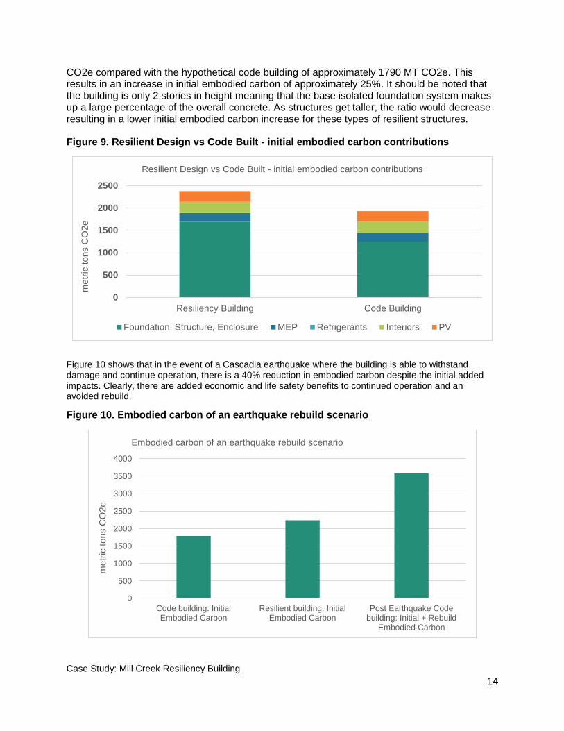
The interiors analysis of this project include ceiling and floor finishes, doors, interior walls, casework, and interior glazing. Plumbing and light fixtures were excluded because they were already included in the MEP estimates. Overall, the project team’s detailed accounting of interior finishes identified areas with high carbon impacts such as cubicles, chairs, partition walls, carpet, tables, certain door types, and interior glazing as shown in Figure 8. Any material with total impacts less than 3% of the total interior impacts was grouped together into the “other” category. Originally, the impacts of carpet were modelled twice as large as seen in Figure 8 but the project team requested an EPD from the supplier (Interface) and impacts were adjusted downward. In this case, the availability of an EPD for carpet helped with material transparency and modelling efforts but it didn’t affect the purchasing decision, because the chosen product already had low carbon within the range of carpet products available. Interior impacts add up significantly over time. In this analysis, the team assumed that all interior materials were replaced every 20 years. For a standard commercial building rented at market rates, the rates of tenant improvement projects are typically every 10-20 years. The team extended the replacement rate to 20 years for this project because this building will be leased long-term to a single state agency. Strategies to reduce the accumulated impacts of interior materials are through extended product lifetime (durability), repair rather than replacement of systems, and sourcing lower impact replacement materials.
Rendering provided by GBD Architects

Case Study: Mill Creek Resiliency Building
13
Figure 8. Embodied carbon of Interior materials as a percent of total initial impacts
Alternative Construction Scenarios
Resilient Design vs Code Built
The building has an advanced seismic resisting system specifically designed for resilience and uninterrupted operation in the event of a large Cascadia Subduction Zone earthquake. The Structural Engineer, KPFF, provided an estimate of material quantities for a similar structure built to only meet code requirements in order to provide a comparison. In general, designing to this highest level of resiliency using a base isolated structure will require more construction material and associated carbon. However, these increases should be evaluated and compared based on the probability of undergoing significant seismic damage during its useful life. A typical code building may require complete demolition and re-build in this condition vs. a base isolated structure, which may only require minor to no repair. For this project, the base isolated structure increased overall material quantities by approximately 60% and 33% for concrete volume and steel tonnage, respectively. Figure 9 shows that the resilient structure has an initial embodied carbon impact of 2238 MT
Other18%
carpet6%
interior glazing4%
door type 57%
door type 63%
partition wall17%
chair13%
cubicle26%
table6%
Embodied carbon of Interior materials as a percent of total initial impacts
Base isolation node in the seismically stable foundation system
Case Study: Mill Creek Resiliency Building
14
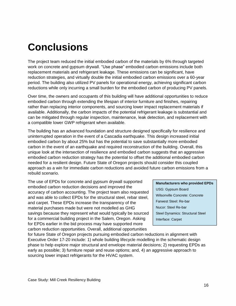
CO2e compared with the hypothetical code building of approximately 1790 MT CO2e. This results in an increase in initial embodied carbon of approximately 25%. It should be noted that the building is only 2 stories in height meaning that the base isolated foundation system makes up a large percentage of the overall concrete. As structures get taller, the ratio would decrease resulting in a lower initial embodied carbon increase for these types of resilient structures.
Figure 9. Resilient Design vs Code Built - initial embodied carbon contributions
Figure 10 shows that in the event of a Cascadia earthquake where the building is able to withstand damage and continue operation, there is a 40% reduction in embodied carbon despite the initial added impacts. Clearly, there are added economic and life safety benefits to continued operation and an avoided rebuild.
Figure 10. Embodied carbon of an earthquake rebuild scenario
0
500
1000
1500
2000
2500
Resiliency Building Code Building
metr
ic tons C
O2e
Resilient Design vs Code Built - initial embodied carbon contributions
Foundation, Structure, Enclosure MEP Refrigerants Interiors PV
0
500
1000
1500
2000
2500
3000
3500
4000
Code building: InitialEmbodied Carbon
Resilient building: InitialEmbodied Carbon
Post Earthquake Codebuilding: Initial + Rebuild
Embodied Carbon
metr
ic tons C
O2e
Embodied carbon of an earthquake rebuild scenario

Case Study: Mill Creek Resiliency Building
15
Net zero with PV panels vs Non PV panels building
The use of PV panels significantly reduced operational carbon emissions while only incurring a small additional embodied carbon impact for the production of the PV panels. The embodied carbon impacts of producing the initial PV panels were offset after two years of operational carbon savings. Over the 60-year lifetime, the panels are only expected to be replaced once. The impact of producing these replacement panels would be offset after two years of operational GHG savings. Thus, in total, over the 60-year lifetime of the building the net benefits of the PV panels would be accruing for 56 out of the 60 years. In other words, from an embodied carbon perspective, PV panels pay for themselves quickly. Figure 11 below shows the difference between the constructed building with PV panels and the exact same building operating without PV panels. For this building, PV reduced the lifecycle greenhouse gas emissions of this building by roughly 66%
Figure 11. Carbon impacts of Resilience Building by lifecycle stage (60 year lifespan)
-2000
0
2000
4000
6000
8000
10000
12000
14000
PRODUCT(A1 to A3)
CONSTRUCTIONPROCESS(A4 & A5)
USE(B2, B4 & B6)
END OF LIFE(C1 to C4)
BEYONDBUILDING LIFE
(D)
TOTAL EFFECTS(A to D)
metr
ic tons C
O2e
Carbon impacts of Resilience Building by lifecycle stage (60 year lifespan)
No PV used Constructed with PV
Case Study: Mill Creek Resiliency Building
16
Conclusions
The project team reduced the initial embodied carbon of the materials by 6% through targeted
work on concrete and gypsum drywall. “Use phase” embodied carbon emissions include both
replacement materials and refrigerant leakage. These emissions can be significant, have
reduction strategies, and virtually double the initial embodied carbon emissions over a 60-year
period. The building also utilized PV panels for operational energy, achieving significant carbon
reductions while only incurring a small burden for the embodied carbon of producing PV panels.
Over time, the owners and occupants of this building will have additional opportunities to reduce
embodied carbon through extending the lifespan of interior furniture and finishes, repairing
rather than replacing interior components, and sourcing lower impact replacement materials if
available. Additionally, the carbon impacts of the potential refrigerant leakage is substantial and
can be mitigated through regular inspection, maintenance, leak detection, and replacement with
a compatible lower GWP refrigerant when available.
The building has an advanced foundation and structure designed specifically for resilience and
uninterrupted operation in the event of a Cascadia earthquake. This design increased initial
embodied carbon by about 25% but has the potential to save substantially more embodied
carbon in the event of an earthquake and required reconstruction of the building. Overall, this
unique look at the intersection of resilience and embodied carbon suggests that an aggressive
embodied carbon reduction strategy has the potential to offset the additional embodied carbon
needed for a resilient design. Future State of Oregon projects should consider this coupled
approach as a win for immediate carbon reductions and avoided future carbon emissions from a
rebuild scenario.
The use of EPDs for concrete and gypsum drywall supported
embodied carbon reduction decisions and improved the
accuracy of carbon accounting. The project team also requested
and was able to collect EPDs for the structural steel, rebar steel,
and carpet. These EPDs increase the transparency of the
material purchases made but were not modelled as GHG
savings because they represent what would typically be sourced
for a commercial building project in the Salem, Oregon. Asking
for EPDs earlier in the bid process may have supported more
carbon reduction opportunities. Overall, additional opportunities
for future State of Oregon projects pursuing embodied carbon reductions in alignment with
Executive Order 17-20 include: 1) whole building lifecycle modelling in the schematic design
phase to help explore major structural and envelope material decisions; 2) requesting EPDs as
early as possible; 3) furniture repair and reuse options; and, 4) an aggressive approach to
sourcing lower impact refrigerants for the HVAC system.
Manufacturers who provided EPDs
USG: Gypsum Board
Wilsonville Concrete: Concrete
Farwest Steel: Re-bar
Nucor: Steel Re-bar
Steel Dynamics: Structural Steel
Interface: Carpet

Case Study: Mill Creek Resiliency Building
17
Limitations:
1. These impacts are estimates only. 2. A wide variety of data sources were used to estimate GHG impacts. There is uncertainty both within
datasets and across different datasets. 3. Site work materials (asphalt + concrete for parking and walking paths) were excluded from this
analysis. 4. Estimates for MEP are based on impact/sf averages taken from a study of multiple buildings and
scaled to the size of the Mill Creek Resiliency Building as opposed to actual quantities of these materials used in Mill Creek building. The data sources are outlined in the methodology section above.
5. End of life impacts were not included for MEP, interiors, and PV due to lack of data. 6. There is a small benefit for “beyond building life” shown in this analysis due to the GHG savings of
material recycling. The recycling rates for the materials are likely undervalued since Oregon typically has a higher recycling rate than other regions.
7. WBLCA has a greater potential to influence and reduce building impacts when used early in design to inform design decisions. In this project, Oregon DEQ wasn’t able to engage with the project until 50% DD stage, when most of the major structural, design, and major material-related decisions had already been made.
8. Per EO 17-20, this analysis focuses exclusively on GHGs. A broader view of environmental, economic, and social impacts and trade-offs can be helpful in weighing project decisions.


