1
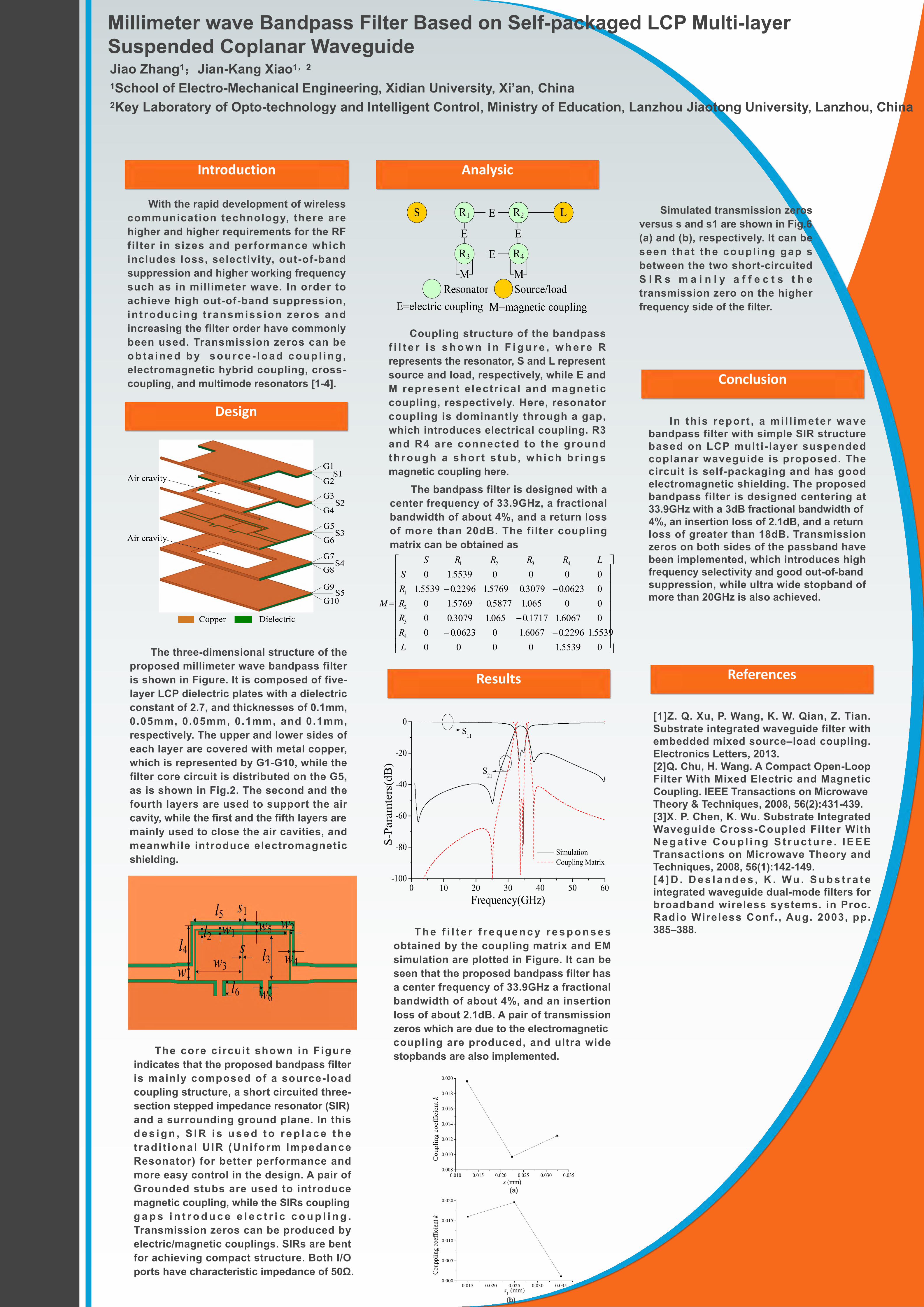
With the rapid development of wireless communication technology, there are higher and higher requirements for the RF filter in sizes and performance which includes loss, selectivity, out-of-band suppression and higher working frequency such as in millimeter wave. In order to achieve high out-of-band suppression, introducing transmission zeros and increasing the filter order have commonly been used. Transmission zeros can be obtained by source-load coupling, electromagnetic hybrid coupling, cross- coupling, and multimode resonators [1-4]. Introduction Design Analysic Conclusion The three-dimensional structure of the proposed millimeter wave bandpass filter is shown in Figure. It is composed of five- layer LCP dielectric plates with a dielectric constant of 2.7, and thicknesses of 0.1mm, 0.05mm, 0.05mm, 0.1mm, and 0.1mm, respectively. The upper and lower sides of each layer are covered with metal copper, which is represented by G1-G10, while the filter core circuit is distributed on the G5, as is shown in Fig.2. The second and the fourth layers are used to support the air cavity, while the first and the fifth layers are mainly used to close the air cavities, and meanwhile introduce electromagnetic shielding. Coupling structure of the bandpass filter is shown in Figure, where R represents the resonator, S and L represent source and load, respectively, while E and M represent electrical and magnetic coupling, respectively. Here, resonator coupling is dominantly through a gap, which introduces electrical coupling. R3 and R4 are connected to the ground through a short stub, which brings magnetic coupling here. Millimeter wave Bandpass Filter Based on Self-packaged LCP Multi-layer Suspended Coplanar Waveguide Jiao Zhang 1 ;Jian-Kang Xiao 1,2 1 School of Electro-Mechanical Engineering, Xidian University, Xi’an, China 2 Key Laboratory of Opto-technology and Intelligent Control, Ministry of Education, Lanzhou Jiaotong University, Lanzhou, China In this report, a millimeter wave bandpass filter with simple SIR structure based on LCP multi-layer suspended coplanar waveguide is proposed. The circuit is self-packaging and has good electromagnetic shielding. The proposed bandpass filter is designed centering at 33.9GHz with a 3dB fractional bandwidth of 4%, an insertion loss of 2.1dB, and a return loss of greater than 18dB. Transmission zeros on both sides of the passband have been implemented, which introduces high frequency selectivity and good out-of-band suppression, while ultra wide stopband of more than 20GHz is also achieved. References [1]Z. Q. Xu, P. Wang, K. W. Qian, Z. Tian. Substrate integrated waveguide filter with embedded mixed source–load coupling. Electronics Letters, 2013. [2]Q. Chu, H. Wang. A Compact Open-Loop Filter With Mixed Electric and Magnetic Coupling. IEEE Transactions on Microwave Theory & Techniques, 2008, 56(2):431-439. [3]X. P. Chen, K. Wu. Substrate Integrated Waveguide Cross-Coupled Filter With Negative Coupling Structure. IEEE Transactions on Microwave Theory and Techniques, 2008, 56(1):142-149. [4]D. Deslandes, K. Wu. Substrate integrated waveguide dual-mode filters for broadband wireless systems. in Proc. Radio Wireless Conf., Aug. 2003, pp. 385–388. The core circuit shown in Figure indicates that the proposed bandpass filter is mainly composed of a source-load coupling structure, a short circuited three- section stepped impedance resonator (SIR) and a surrounding ground plane. In this design, SIR is used to replace the traditional UIR (Uniform Impedance Resonator) for better performance and more easy control in the design. A pair of Grounded stubs are used to introduce magnetic coupling, while the SIRs coupling gaps introduce electric coupling. Transmission zeros can be produced by electric/magnetic couplings. SIRs are bent for achieving compact structure. Both I/O ports have characteristic impedance of 50Ω. 0 5539 . 1 0 0 0 0 5539 . 1 2296 . 0 6067 . 1 0 0623 . 0 0 0 6067 . 1 1717 . 0 065 . 1 3079 . 0 0 0 0 065 . 1 5877 . 0 5769 . 1 0 0 0623 . 0 3079 . 0 5769 . 1 2296 . 0 5539 . 1 0 0 0 0 5539 . 1 0 4 3 2 1 4 3 2 1 L R R R R S L R R R R S M The bandpass filter is designed with a center frequency of 33.9GHz, a fractional bandwidth of about 4%, and a return loss of more than 20dB. The filter coupling matrix can be obtained as Results 0 10 20 30 40 50 60 -100 -80 -60 -40 -20 0 S-Paramters(dB) Frequency(GHz) Simulation Coupling Matrix S 11 S 21 The filter frequency responses obtained by the coupling matrix and EM simulation are plotted in Figure. It can be seen that the proposed bandpass filter has a center frequency of 33.9GHz a fractional bandwidth of about 4%, and an insertion loss of about 2.1dB. A pair of transmission zeros which are due to the electromagnetic coupling are produced, and ultra wide stopbands are also implemented. 0.015 0.020 0.025 0.030 0.035 0.000 0.005 0.010 0.015 0.020 Couppling coefficient k s 1 (mm) Simulated transmission zeros versus s and s1 are shown in Fig.6 (a) and (b), respectively. It can be seen that the coupling gap s between the two short-circuited SIRs mainly affects the transmission zero on the higher frequency side of the filter. 0.010 0.015 0.020 0.025 0.030 0.035 0.008 0.010 0.012 0.014 0.016 0.018 0.020 Coupling coefficient k s (mm) (a) (b)