14
ETSI SUMMIT: 5G FROM MYTH TO REALITY MILLIMETER‐WAVE FOR 5G, BACKHAUL AND ACCESS Renato Lombardi, Chairman of ISG mWT © All rights reserved
ETSI SUMMIT:5G FROM MYTH TO REALITY
MILLIMETER‐WAVE FOR 5G,BACKHAUL AND ACCESSRenato Lombardi, Chairman of ISG mWT
© All rights reserved
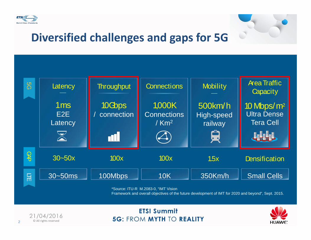
Diversified challenges and gaps for 5G
2 © All rights reserved
Area Traffic Capacity
10 Mbps/m2
Ultra DenseTera Cell
Connections
1,000KConnections
/ Km2
Mobility
500km/hHigh-speed
railway
Throughput
10Gbps/ connection
Latency
1 msE2E
Latency
5G
100Mbps 10K 350Km/h30~50ms Small Cells
LTEGAP 30~50x 100x 100x 1.5x Densification
*Source: ITU-R M.2083-0, “IMT VisionFramework and overall objectives of the future development of IMT for 2020 and beyond”, Sept. 2015.
How to meet the demand of the capacity increase
3 © All rights reserved
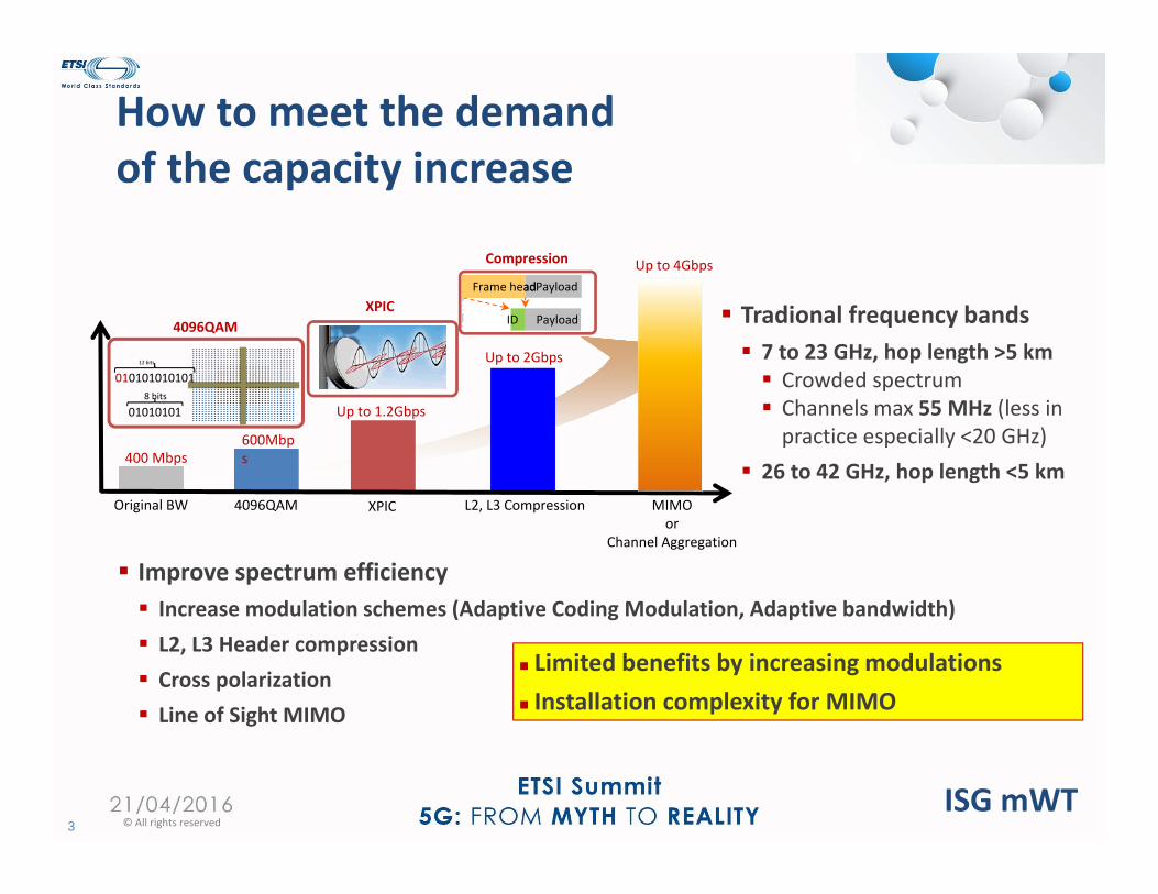
Original BW 4096QAM XPIC L2, L3 Compression
400 Mbps600Mbps
Up to 1.2Gbps
Up to 2Gbps010101010101
12 bits
010101018 bits
4096QAM PayloadID
PayloadFrame headFrame head
Compression
XPIC
Up to 4Gbps
MIMOor
Channel Aggregation
Improve spectrum efficiency Increase modulation schemes (Adaptive Coding Modulation, Adaptive bandwidth) L2, L3 Header compression Cross polarization Line of Sight MIMO
Limited benefits by increasing modulations Installation complexity for MIMO
Tradional frequency bands 7 to 23 GHz, hop length >5 km Crowded spectrum Channels max 55 MHz (less in practice especially <20 GHz)
26 to 42 GHz, hop length <5 km
ISG mWT
How to meet the demand of the capacity increase
4 © All rights reserved
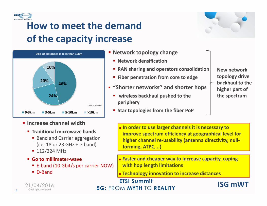
Increase channel width Traditional microwave bands Band and Carrier aggregation (i.e. 18 or 23 GHz + e‐band) 112/224 MHz Go to millimeter‐wave E‐band (10 Gbit/s per carrier NOW) D‐Band
In order to use larger channels it is necessary to improve spectrum efficiency at geographical level for higher channel re‐usability (antenna directivity, null‐forming, ATPC, ..)
Faster and cheaper way to increase capacity, coping with hop length limitations
Technology innovation to increase distances
Source : Huawei
46%
24%
20%
10%
0‐3km 3‐5km 5‐10km >10km
90% of distances is less than 10km Network topology change Network densification RAN sharing and operators consolidation Fiber penetration from core to edge
‘’Shorter networks’’ and shorter hops wireless backhaul pushed to the periphery Star topologies from the fiber PoP
New network topology drive backhaul to the higher part of the spectrum
ISG mWT
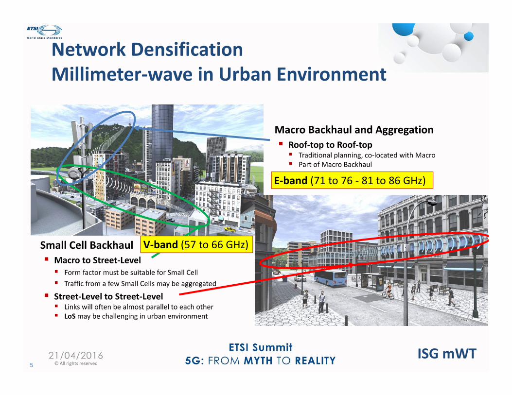
Network DensificationMillimeter‐wave in Urban Environment
5 © All rights reserved
Small Cell Backhaul Macro to Street‐Level Form factor must be suitable for Small Cell Traffic from a few Small Cells may be aggregated
Street‐Level to Street‐Level Links will often be almost parallel to each other LoSmay be challenging in urban environment
Macro Backhaul and Aggregation Roof‐top to Roof‐top Traditional planning, co‐located with Macro Part of Macro Backhaul
E‐band (71 to 76 ‐ 81 to 86 GHz)
V‐band (57 to 66 GHz)
ISG mWT

E‐band & V‐band Licensing Worldwide
6 © All rights reserved
V‐BAND LICENSES
Individual Licensing
Light Licensing
Block Assignment
LicenseExempt
Current
Desired
V‐band
Work in progress in ISG mWT
ISG mWT
FDD
10010 20 30 40 50 60 70 80 90
6 11 13 15 18 23 26 38 71 – 86 GHz7/8 42 GHz 50 55 57 – 66 GHz28 32 92 – 95 GHz
E‐BAND LICENSES
Individual Licensing
Light Licensing
Block Assignment
LicenseExempt
Current
Desired
Green OpenRed ClosedBlue Under ReviewGrey No info
E‐band
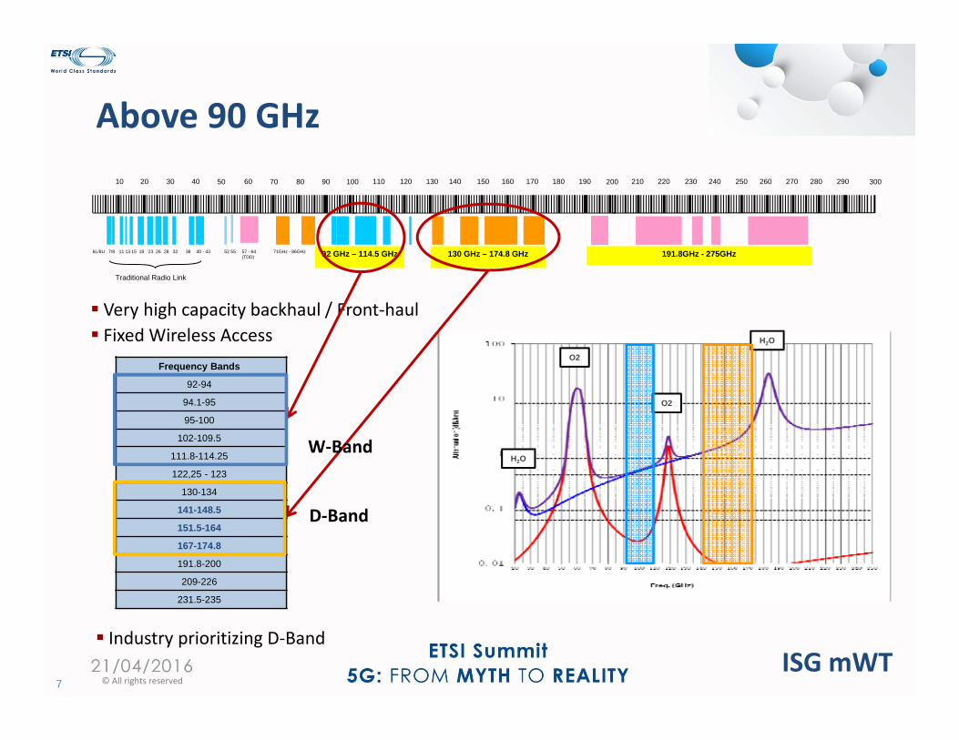
Above 90 GHz
7 © All rights reserved
Very high capacity backhaul / Front‐haul Fixed Wireless Access
H2O
O2
O2
H2O
6L/6U
Traditional Radio Link
10010 20 30 40 50 60 70 80 90
11 13 15 18 23 26 38 71GHz - 86GHz7/8 40 - 43 52 55 57 - 64 (TDD)
28 32
200110 120 130 140 150 160 170 180 190 300210 220 230 240 250 260 270 280 290
191.8GHz - 275GHz92 GHz – 114.5 GHz 130 GHz – 174.8 GHz
Frequency Bands
92-94
94.1-95
95-100
102-109.5
111.8-114.25
122,25 - 123
130-134
141-148.5
151.5-164
167-174.8
191.8-200
209-226
231.5-235
W‐Band
D‐Band
ISG mWT Industry prioritizing D‐Band
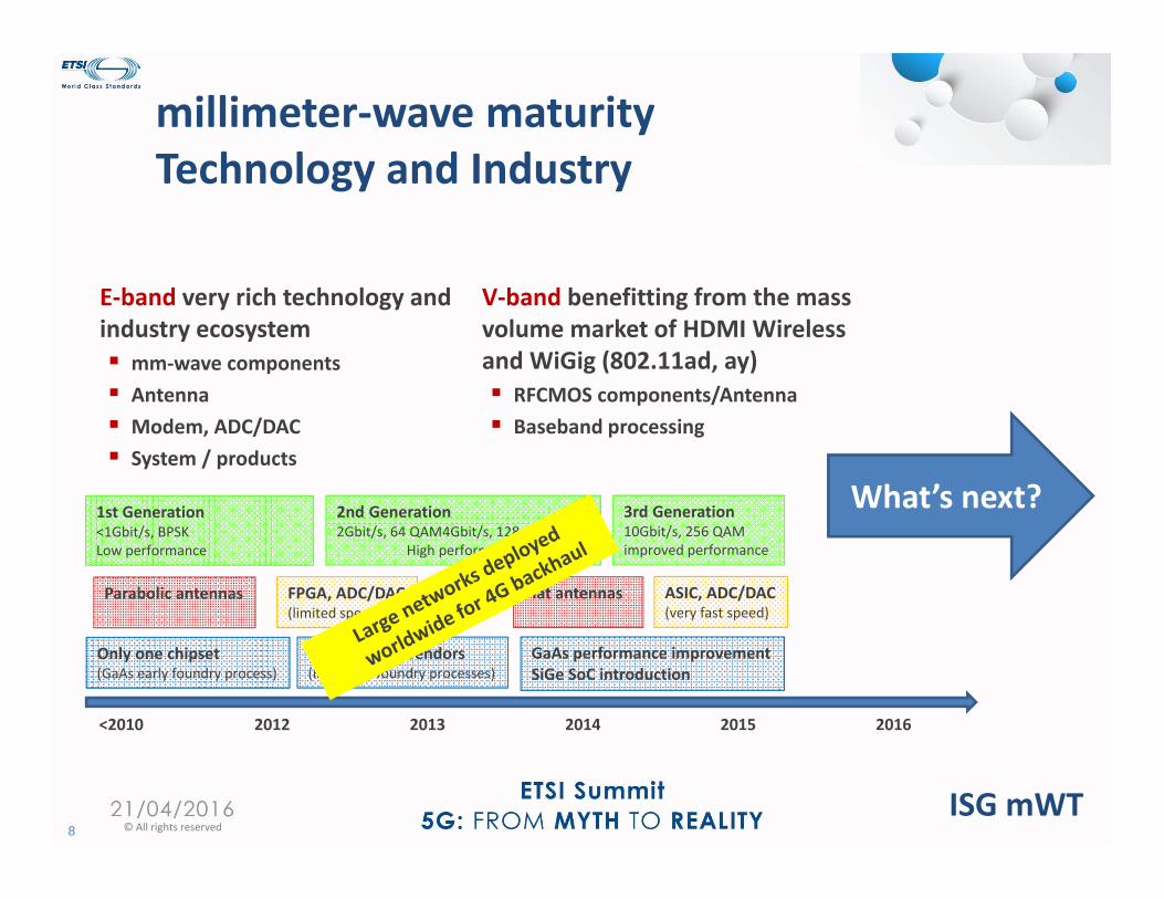
millimeter‐wave maturityTechnology and Industry
8 © All rights reserved
E‐band very rich technology and industry ecosystem mm‐wave components Antenna Modem, ADC/DAC System / products
<2010 2012 2013 2014 2015 2016
Only one chipset(GaAs early foundry process)
Several GaAs vendors(improved foundry processes)
GaAs performance improvementSiGe SoC introduction
Parabolic antennas Flat antennasFPGA, ADC/DAC(limited speed)
ASIC, ADC/DAC(very fast speed)
1st Generation<1Gbit/s, BPSKLow performance
2nd Generation2Gbit/s, 64 QAM4Gbit/s, 128 QAM
High performance
3rd Generation 10Gbit/s, 256 QAMimproved performance
What’s next?
V‐band benefitting from the mass volume market of HDMI Wireless and WiGig (802.11ad, ay) RFCMOS components/Antenna Baseband processing
ISG mWT
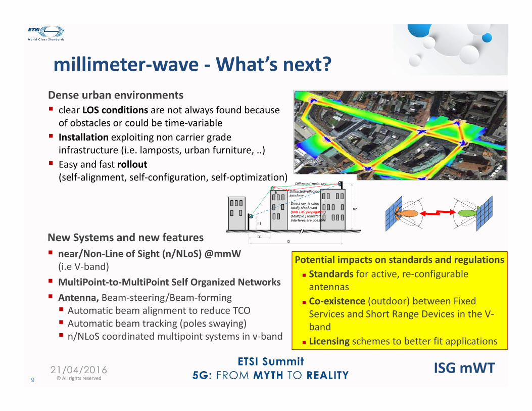
millimeter‐wave ‐What’s next?
9 © All rights reserved
Dense urban environments clear LOS conditions are not always found because of obstacles or could be time‐variable Installation exploiting non carrier grade infrastructure (i.e. lamposts, urban furniture, ..) Easy and fast rollout(self‐alignment, self‐configuration, self‐optimization)
New Systems and new features near/Non‐Line of Sight (n/NLoS) @mmW (i.e V‐band) MultiPoint‐to‐MultiPoint Self Organized Networks Antenna, Beam‐steering/Beam‐forming Automatic beam alignment to reduce TCO Automatic beam tracking (poles swaying) n/NLoS coordinated multipoint systems in v‐band
h1
h2
h
Direct ray is oftentotally shadowed(non-LoS propagation)(Multiple ) reflectedInterferes are possible
Diffracted ‘main’ ray
Diffracted/reflectedinterferer
D1D
Potential impacts on standards and regulations Standards for active, re‐configurable antennas
Co‐existence (outdoor) between Fixed Services and Short Range Devices in the V‐band
Licensing schemes to better fit applications
ISG mWT
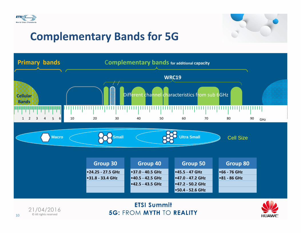
Complementary Bands for 5G
10 © All rights reserved
Cell SizeMacro Small Ultra Small
WRC19
10 50403020 60 8070 90 GHz
Different channel characteristics from sub 6GHz
1 542 63
Cellular Bands
Complementary bands for additional capacityPrimary bands
Group 30 Group 40 Group 50 Group 80•24.25 ‐ 27.5 GHz •37.0 ‐ 40.5 GHz •45.5 ‐ 47 GHz •66 ‐ 76 GHz•31.8 ‐ 33.4 GHz •40.5 ‐ 42.5 GHz •47.0 ‐ 47.2 GHz •81 ‐ 86 GHz
•42.5 ‐ 43.5 GHz •47.2 ‐ 50.2 GHz•50.4 ‐ 52.6 GHz
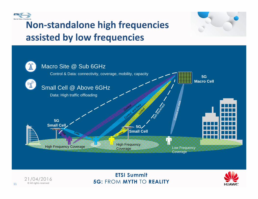
Non‐standalone high frequencies assisted by low frequencies
11 © All rights reserved
Macro Site @ Sub 6GHzControl & Data: connectivity, coverage, mobility, capacity
Small Cell @ Above 6GHzData: High traffic offloading
5GMacro Cell
High Frequency Coverage High Frequency Coverage Low Frequency
Coverage
5GSmall Cell 5G
Small Cell
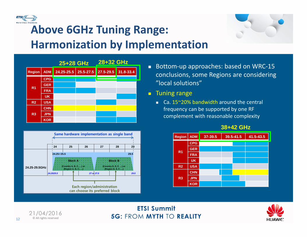
Above 6GHz Tuning Range: Harmonization by Implementation
12 © All rights reserved
Region ADM 37-39.5 39.5-41.5 41.5-43.5
R1
CPGGERFRAUK
R2 USA
R3CHNJPNKOR
Region ADM 24.25-25.5 25.5-27.5 27.5-29.5 31.8-33.4
R1
CPGGERFRAUK
R2 USA
R3CHNJPNKOR
Bottom‐up approaches: based on WRC‐15 conclusions, some Regions are considering ”local solutions”
Tuning range: Ca. 15~20% bandwidth around the central
frequency can be supported by one RF complement with reasonable complexity
24 25 26 27 28 29
24.25-29.5GHz
24.25 / 25.5 29.5
24.25/25.5 29.5
Block A
(Country A, B, C, …) or(Region A, B, C, …)
Block B
(Country D, E, F, …) or(Region D, E, F, …)
27 or 27.5
Same hardware implementation as single band
Each region/administration can choose its preferred block
25+28 GHz 28+32 GHz
38+42 GHz
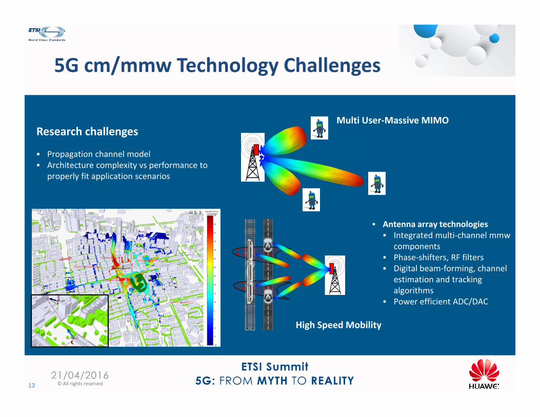
5G cm/mmw Technology Challenges
13 © All rights reserved
Research challenges
Propagation channel model Architecture complexity vs performance to
properly fit application scenarios
High Speed Mobility
Multi User‐Massive MIMO
Antenna array technologies Integrated multi‐channel mmw
components Phase‐shifters, RF filters Digital beam‐forming, channel
estimation and tracking algorithms
Power efficient ADC/DAC
Thank you
14 © All rights reservedISG mWT


