Page 1
Millimeter-Wave Human Blockage at 73 GHz with
a Simple Double Knife-Edge Diffraction Model
and Extension for Directional Antennas
IEEE VTC2016-Fall, Montreal, Canada, Sept. 20, 2016
George R. MacCartney Jr., Sijia Deng, Shu Sun,and Theodore S. Rappaport
{gmac,sijia,ss7152,tsr}@nyu.edu
2016 NYU WIRELESSG. R. MacCartney, Jr., S. Deng, S. Sun, and T. S. Rappaport, “Millimeter-
Wave Human Blockage at 73 GHz with a Simple Double Knife-Edge
Diffraction Model and Extension for Directional Antennas,” 2016 IEEE
84th Vehicular Technology Conference: VTC2016-Fall, Montreal, Canada,
Sept. 2016.
Page 2
• Human Blockage in Channel Models
• Knife-Edge Diffraction Models
• Measurement System and Specifications
• Measurement Environment, Setup, and Test Description
• Measurement Results
• Observations and Conclusions
Agenda
2
Page 3
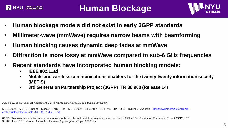
• Human blockage models did not exist in early 3GPP standards
• Millimeter-wave (mmWave) requires narrow beams with beamforming
• Human blocking causes dynamic deep fades at mmWave
• Diffraction is more lossy at mmWave compared to sub-6 GHz frequencies
• Recent standards have incorporated human blocking models:• IEEE 802.11ad
• Mobile and wireless communications enablers for the twenty-twenty information society
(METIS)
• 3rd Generation Partnership Project (3GPP) TR 38.900 (Release 14)
Human Blockage
3
A. Maltsev, et al., “Channel models for 60 GHz WLAN systems,” IEEE doc. 802.11-09/0334r4
METIS2020, “METIS Channel Model,” Tech. Rep. METIS2020, Deliverable D1.4 v3, July 2015. [Online]. Available: https://www.metis2020.com/wp-
content/uploads/deliverables/METIS_D1.4_v1.0.pdf
3GPP, “Technical specification group radio access network; channel model for frequency spectrum above 6 GHz,” 3rd Generation Partnership Project (3GPP), TR
38.900, June. 2016. [Online]. Available: http://www.3gpp.org/DynaReport/38900.htm
Page 4
IEEE 802.11ad Human Blockage
4
Figure from: A. Maltsev, et al., “Channel models for 60 GHz WLAN systems,”
IEEE doc. 802.11-09/0334r8
• Statistical distributions used to
simulate human blockage for: decay
time, rise time, duration, and mean
attenuation
• Mostly ray-tracing simulations and
few measurements used to create
the model
6.6 6.7 6.8 6.9 7 7.1 7.2 7.3
20
15
10
5
0
Time [s]
Attenuatio
n [dB
]
Shadow fading event
Duration tD
Mean Att. Amean
tdecay t
rise
Page 5
METIS Human Blockage
5
• METIS2020, “METIS Channel Model,” Tech. Rep. METIS2020, Deliverable D1.4 v3, July 2015. [Online]. Available: https://www.metis2020.com/wp-
content/uploads/deliverables/METIS_D1.4_v1.0.pdf
• J. Medbo and F. Harrysson, “Channel modeling for the stationary UE scenario,” Antennas and Propagation (EuCAP), 2013 7th European Conference on, Gothenburg, 2013, pp. 2811-
2815.
• Human walking in front of antennas at 60 GHz for a 4 m T-R separation distance
• Limited measurements compared to model for validation
• Approximation of knife-edge diffraction (KED) from multiple edges used for model
• Originally based on measurements with dipole antennas (omnidirectional)
Page 6
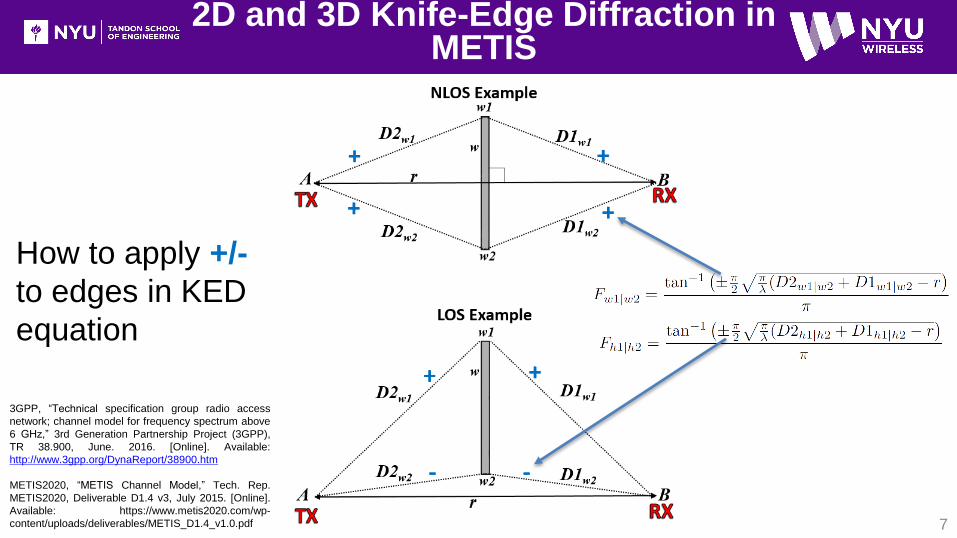
METIS blockage model • Shadowing by 4 screen edges:
where for ±, the plus (+) indicates the shadow zone and the minus (-)
indicates the LOS zone. For a region where there is a clear LOS, the edge
closest to the LOS is considered the LOS zone and the edge farthest from
the LOS is considered the shadow zone (see next slide).
• KED Shadowing loss (four edges):
• Double knife-edge diffraction (DKED) shadowing loss
(2D, infinitely high screen) :
3D and 2D Knife-Edge Diffraction in METIS
6METIS2020, “METIS Channel Model,” Tech. Rep. METIS2020, Deliverable D1.4 v3, July 2015. [Online]. Available:
https://www.metis2020.com/wp-content/uploads/deliverables/METIS_D1.4_v1.0.pdf
3D View
Top-down View
Side View
F = E-field gain due to diffraction
Fw1|w2 = Fw1 or Fw2
Page 7
2D and 3D Knife-Edge Diffraction in METIS
7
How to apply +/-
to edges in KED
equation
3GPP, “Technical specification group radio access
network; channel model for frequency spectrum above
6 GHz,” 3rd Generation Partnership Project (3GPP),
TR 38.900, June. 2016. [Online]. Available:
http://www.3gpp.org/DynaReport/38900.htm
METIS2020, “METIS Channel Model,” Tech. Rep.
METIS2020, Deliverable D1.4 v3, July 2015. [Online].
Available: https://www.metis2020.com/wp-
content/uploads/deliverables/METIS_D1.4_v1.0.pdf
Page 8
3D Knife-Edge Diffraction in 3GPP
8
• 3GPP has two different KED human blockage models
• Model A: based on polar coordinates, but similar to METIS
(see page 48 of 3GPP TR 38.900 V14.0.0)
• Model B: based on Cartesian coordinates and identical to
the METIS model (see page 50 of 3GPP TR 38.900
V14.0.0)
3GPP, “Technical specification group radio access network; channel model for frequency spectrum above 6 GHz,” 3rd Generation Partnership Project (3GPP), TR 38.900, June. 2016. [Online].
Available: http://www.3gpp.org/DynaReport/38900.htm
METIS2020, “METIS Channel Model,” Tech. Rep. METIS2020, Deliverable D1.4 v3, July 2015. [Online]. Available: https://www.metis2020.com/wp-
content/uploads/deliverables/METIS_D1.4_v1.0.pdf
Page 9
Human blockage with directional antennas
9
Br
A
w2
w1
• Neither METIS or 3GPP account for high gain antennas
• High gain antennas do not have uniform gain across a human blocker
or screen
• This error is greatest when the human blocker is close to TX or RX
(0.5 to 1.5 meters)
Page 10
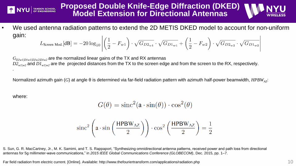
• We used antenna radiation patterns to extend the 2D METIS DKED model to account for non-uniform
gain:
GD2w1|D1w1|D2w2|D1w2 are the normalized linear gains of the TX and RX antennas
D2w1|w2 and D1w1|w2 are the projected distances from the TX to the screen edge and from the screen to the RX, respectively.
.
Normalized azimuth gain (G) at angle θ is determined via far-field radiation pattern with azimuth half-power beamwidth, HPBWAZ:
where:
Proposed Double Knife-Edge Diffraction (DKED) Model Extension for Directional Antennas
10
S. Sun, G. R. MacCartney, Jr., M. K. Samimi, and T. S. Rappaport, “Synthesizing omnidirectional antenna patterns, received power and path loss from directional
antennas for 5g millimeter-wave communications,” in 2015 IEEE Global Communications Conference (GLOBECOM), Dec. 2015, pp. 1–7.
Far field radiation from electric current. [Online]. Available: http://www.thefouriertransform.com/applications/radiation.php
Page 11
Measurement System Specifications
11
Description Specification
Baseband Sequence PRBS (11th order: 211-1 = Length 2047)
Chip Rate 500 Mcps
RF Null-to-Nulll Bandwidth 1 GHz
PDP Detection FFT matched filter
Sampling Rate 1.5 GS/s I and Q
Multipath Time Resolution 2 ns
Minimum Periodic PDP Interval 32.752 μs
Maximum Frequency Interval 30.053 kHz (±15.2 kHz max Doppler)
Maximum Periodic PDP records per snapshot 41,000 PDPs
PDP Threshold 25 dB down from max peak
TX/RX Intermediate Frequency 5.625 GHz
TX/RX LO 67.875 GHz (22.625 GHz x3)
Synchronization TX/RX Share 10 MHz Reference
Carrier Frequency 73.5 GHz
TX Power -5.8 dBm
TX/RX Antenna Gain 20 dBi
TX/RX Azimuth and Elevation HPBW 15º
TX/RX Antenna Polarization V-V
EIRP 14.2 dBm
TX/RX Heights 1.4 m
TX RX
• Real-time spread spectrum sequence
wideband correlator channel sounder
• Measurement specific details:
• 5 second capture window that
records 500 PDPs/second (2500
total PDPs)
G. R. MacCartney, Jr., S. Deng, S. Sun, and T. S. Rappaport, “Millimeter-Wave Human Blockage at
73 GHz with a Simple Double Knife-Edge Diffraction Model and Extension for Directional Antennas,”
2016 IEEE 84th Vehicular Technology Conference: VTC2016-Fall, Montreal, Canada, Sept. 2016.
Page 12
Measurement Environment / Setup
12
• Measurements for a T-R separation distance of 5 m for 9 discrete
blockage positions between the TX and RX from 0.5 m to 4.5 m in
0.5 m increments
• Fraunhofer distance of antennas at 73.5 GHz: 0.292 m
• Human blocker moves at approximate speed of 1 m/s with body
depth (0.28 m) blocking LOS.
Page 13
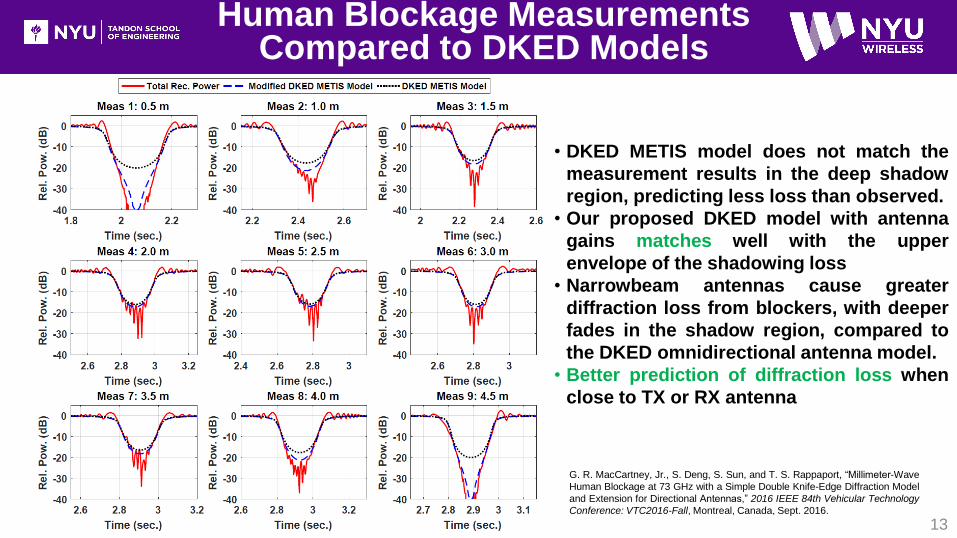
Human Blockage Measurements Compared to DKED Models
13
• DKED METIS model does not match the
measurement results in the deep shadow
region, predicting less loss than observed.
• Our proposed DKED model with antenna
gains matches well with the upper
envelope of the shadowing loss
• Narrowbeam antennas cause greater
diffraction loss from blockers, with deeper
fades in the shadow region, compared to
the DKED omnidirectional antenna model.
• Better prediction of diffraction loss when
close to TX or RX antenna
G. R. MacCartney, Jr., S. Deng, S. Sun, and T. S. Rappaport, “Millimeter-Wave
Human Blockage at 73 GHz with a Simple Double Knife-Edge Diffraction Model
and Extension for Directional Antennas,” 2016 IEEE 84th Vehicular Technology
Conference: VTC2016-Fall, Montreal, Canada, Sept. 2016.
Page 14
Prediction in Deep Shadow Region
14
• Our modified DKED model that
includes antennas gains at screen
edges and with coherent sum of fields
from both edges matches the upper
bound envelope of the total received
power deep shadowing, representing
constructive interference
• Our modified DKED model that
includes antennas gains at screen
edges and with coherent difference of
fields from both edges matches the
lower bound envelope of the total
received power deep shadowing,
representing destructive interference• M. Jacob et al., "A ray tracing based stochastic human blockage model for the IEEE 802.11ad
60 GHz channel model," Proceedings of the 5th European Conference on Antennas and
Propagation (EUCAP), Rome, 2011, pp. 3084-3088.
• G. R. MacCartney, Jr., S. Deng, S. Sun, and T. S. Rappaport, “Millimeter-Wave Human
Blockage at 73 GHz with a Simple Double Knife-Edge Diffraction Model and Extension for
Directional Antennas,” 2016 IEEE 84th Vehicular Technology Conference: VTC2016-Fall,
Montreal, Canada, Sept. 2016.
Page 15
• Shadowing events lasted between approximately 200 and 300 ms on average
• Reciprocal shadowing observations made at either TX/RX measurement locations such
as 0.5 meters from the TX (Meas 1) and 0.5 meters from the RX (Meas 9)
• Deep fades (maximum attenuation) during shadowing could exceed 40 dB. Less loss
when blocker was further from the TX and RX (Meas 5, 2.5 m from both TX and RX).
• Our modified DKED model with antenna gains can be used to determine minimum and
maximum fade depths caused by human blockage
• Temporal variations and large shadowing events can be overcome by beamsteering to
find scatterers and reflections to improve SNR.
Observations and Conclusion
15
Page 16
16
Acknowledgment
Acknowledgement to our
NYU WIRELESS Industrial
Affiliates and NSF
Grants: 1320472, 1302336, and
1555332
Page 17
17
References
1. G. R. MacCartney, Jr., S. Deng, S. Sun, and T. S. Rappaport, “Millimeter-Wave Human Blockage at 73 GHz with a Simple Double Knife-
Edge Diffraction Model and Extension for Directional Antennas,” 2016 IEEE 84th Vehicular Technology Conference (VTC2016-Fall),
Sept. 2016.
2. S. Sun, G. R. MacCartney, Jr., M. K. Samimi, and T. S. Rappaport, “Synthesizing omnidirectional antenna patterns, received power and
path loss from directional antennas for 5g millimeter-wave communications,” in 2015 IEEE Global Communications Conference
(GLOBECOM), Dec. 2015, pp. 1–7.
3. T. S. Rappaport, G. R. MacCartney, Jr., M. K. Samimi, and S. Sun, “Wideband millimeter-wave propagation measurements and channel
models for future wireless communication system design (Invited Paper),” IEEE Transactions on Communications, vol. 63, no. 9, pp.
3029–3056, Sept. 2015.
4. T. S. Rappaport, S. Sun, R. Mayzus, H. Zhao, Y. Azar, K. Wang, G. N. Wong, J. K. Schulz, M. K. Samimi, and F. Gutierrez, Jr.,
“Millimeter Wave Mobile Communications for 5G Cellular: It Will Work!” IEEE Access, vol. 1, pp. 335–349, May 2013.
5. S. Sun, T. S. Rappaport, R. W. Heath, A. Nix, and S. Rangan, “MIMO for millimeter-wave wireless communications: beamforming,
spatial multiplexing, or both?” IEEE Communications Magazine, vol. 52, no. 12, pp. 110–121, Dec. 2014.
6. H. Wang and T. S. Rappaport, “A parametric formulation of the UTD diffraction coefficient for real-time propagation prediction
modeling,” IEEE Antennas and Wireless Propagation Letters, vol. 4, pp. 253–257, Aug. 2005.
7. R. R. Skidmore, T. S. Rappaport, and A. L. Abbott, “Interactive coverage region and system design simulation for wireless
communication systems in multifloored indoor environments: SMT PLUS,” in Proceedings of the 5th IEEE International Conference on
Universal Personal Communications, vol. 2, Sept. 1996, pp. 646–650.
8. METIS2020, “METIS Channel Model,” Tech. Rep. METIS2020, Deliverable D1.4 v3, July 2015. [Online]. Available:
https://www.metis2020.com/wp-content/uploads/deliverables/METIS_D1.4_v1.0.pdf
9. J. Medbo, J. E. Berg, and F. Harrysson, “Temporal radio channel variations with stationary terminal,” in 2004 IEEE 60th Vehicular
Technology Conference (VTC2004-Fall), vol. 1, Sept. 2004, pp. 91–95.
10. J. Medbo and F. Harrysson, “Channel modeling for the stationary ue scenario,” in 2013 7th European Conference on Antennas and
Propagation (EuCAP), Apr. 2013, pp. 2811–2815.
11. M. Jacob et al., "A ray tracing based stochastic human blockage model for the IEEE 802.11ad 60 GHz channel model," Proceedings of the
5th European Conference on Antennas and Propagation (EUCAP), Rome, 2011, pp. 3084-3088.
Page 18
18
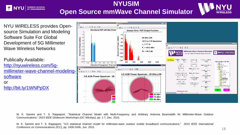
NYUSIM
Open Source mmWave Channel Simulator
NYU WIRELESS provides Open-
source Simulation and Modeling
Software Suite For Global
Development of 5G Millimeter
Wave Wireless Networks
Publically Available:
http://nyuwireless.com/5g-
millimeter-wave-channel-modeling-
software
or
http://bit.ly/1WNPpDX
M. K. Samimi and T. S. Rappaport, "Statistical Channel Model with Multi-Frequency and Arbitrary Antenna Beamwidth for Millimeter-Wave Outdoor
Communications," 2015 IEEE Globecom Workshops (GC Wkshps), pp. 1-7, Dec. 2015.
M. K. Samimi and T. S. Rappaport, "3-D statistical channel model for millimeter-wave outdoor mobile broadband communications," 2015 IEEE International
Conference on Communications (ICC), pp. 2430-2436, Jun. 2015.
Page 19
Thank You!
19
Questions