Page 1
1
LDPC-Coded MIMO Systems With Unknown Block
Fading Channels: Soft MIMO Detector Design, Channel
Estimation, and Code Optimization
Jun Zheng,Student Member, IEEE,and Bhaskar D. Rao,Fellow, IEEE
Department of Electrical and Computer Engineering
University of California, San Diego
La Jolla, CA 92093-0407
E-mail: [email protected] , [email protected]
Abstract
In this paper, we consider the design of a practical LDPC-coded MIMO system composed ofM
transmit andN receive antennas operating in a flat fading environment where channel state information
is assumed to be unavailable both to the transmitter and the receiver. A soft iterative receiver structure
is developed which consists of three main blocks, a soft MIMOdetector and two LDPC component
soft decoders. We first propose at the component level several soft-input soft-output MIMO detectors
whose performances are much better than the conventional MMSE-based detectors. In particular, one
optimal soft MIMO detector and two simplified sub-optimal detectors are developed that do not require an
explicit channel estimate and offer an effective tradeoff between complexity and performance. In addition,
a modified EM-based MIMO detector is developed which completely removes positive feedback between
input and output extrinsic information and provide much better performance compared to the direct EM-
based detector that has strong correlations especially in fast fading channels. At the structural level,
the LDPC-coded MIMO receiver is constructed in an unconventional manner where the soft MIMO
detector and LDPC variable node decoder form one super soft-decoding unit, and the LDPC check node
decoder forms the other component of the iterative decodingscheme. By exploiting the proposed receiver
structure, tractable extrinsic information transfer functions of the component soft decoders are obtained,
which further lead to a simple and efficient LDPC code degree profile optimization algorithm with proven
global optimality and guaranteed convergence from any initialization. Finally, numerical and simulation
results are provided to confirm the advantages of the proposed design approach for the coded MIMO
system.
This research was supported by UC Discovery grant No.02-10109 sponsored by Ericsson.
Page 2
2
I. I NTRODUCTION
Communication systems using multiple antennas at both the transmitter and the receiver have recently
received increased attention due to their ability to provide great capacity increases in a wireless fading
environment [1] [2]. However, MIMO capacity analysis and system design is often based on the assump-
tion that the fading channel coefficient between each transmit and receive antenna pair is perfectly known
at the receiver. This is not a realistic assumption for most practical communication systems especially in
fast fading channels.
For communication systems with unknown channel state information (CSI) at both ends, conventional
receivers usually have a two-phase structure, data-aided channel estimation using the preset training
symbols followed by coherent data detection by treating theestimated channel as the actual channel
coefficients. Due to the importance of channel estimator, which directly determines estimation quality
and hence the overall system performance, various MIMO channel estimation algorithms have been
studied [3]– [5]. However, conventional channel estimators form estimates based only on the training
symbols, thereby failing to make use of the channel information contained in the received data symbols.
Consequently, the two-phase model limits the performance and can not approach the MIMO channel
capacity (or the maximum achievable information rate), especially in a fast fading environment (with
small channel coherence time). Possible solutions to the above problem include use of blind source
signal separation algorithms [6]– [8], MIMO differential modulation [9]– [11], and unitary space-time
modulation (USTM) [12]– [18]. However, none of these schemes can approach the non-coherent MIMO
capacity limit due to their sub-optimal code structure, andin the later case, USTM, only asymptotic (or
the diversity) optimality is achieved in high SNR regimes andthe approach suffers from exponential
decoding complexity.
In order to achieve better spectral efficiency than the conventional data-aided estimation algorithm that
uses large number of training symbols for accurate channel estimation, the so-called code-aided joint
channel estimation and data detection algorithms have recently received much attention. By treating the
unknown channel as unobserved (or missing) data, ML sequence estimation of the coded data frames
using the EM algorithm was proposed by Georghiades [19] and Kaleh [20] over single input single output
fading channels and extended to MIMO channels by Cozzo [21].Alternatively, several recent publications
[22]- [24] have developed EM-based algorithms that can iteratively improve the channel estimate based
on the soft extrinsic information from the outer soft decoder, and the schemes work well in an iterative
receiver structure.
In this paper, we focus on the design of practical LDPC-coded MIMO systems employing a soft
iterative receiver structure consisting of three soft decoding component blocks, a soft MIMO detector
Page 3
3
and two soft LDPC component decoders (variable node and check node decoders). At the component
level, we first propose a soft optimal MIMO detector, which cangenerate soft log likelihood ratio (LLR)
of each coded bit under the condition of unknown CSIR without forming any explicit channel estimate.
Based on the proposed soft optimal detector, we develop two simplified sub-optimal MIMO detectors with
polynomial and log polynomial decoding complexities. In addition, motivated by the EM-based detection
algorithm in [24], we also propose in the MIMO context a modified EM-based detector that completely
removes the positive feedback between the input and output extrinsic information and provides much better
performance compared to the direct EM-based detector that has strong correlations. By analyzing the
mutual information transfer characteristic [25] of the proposed soft MIMO detectors, system performance
of different MIMO detection algorithms are analyzed and compared under various channel conditions.
At the structural level, inspired by the turbo iterative principle [26], the LDPC-coded MIMO receiver is
constructed in an unconventional manner where the soft MIMOdetector and LDPC variable node decoder
form one super soft-decoding unit and the LDPC check node decoder forms the other component of the
iterative decoding scheme. Utilizing the proposed receiver structure, tractable extrinsic information transfer
functions of the component soft decoders are obtained, which lead to a simple and efficient LDPC code
degree profile optimization algorithm. This algorithm is shown to have global optimality and guaranteed
convergence from any initialization, and is an improvementover the sub-optimal manual curve fitting
technique proposed in [27]. Numerical and simulation results of the LDPC-coded MIMO system using
the optimized degree profile further confirm the advantages of the proposed design approach for the
coded MIMO system.
The rest of the paper is organized as follows. Section II describes the LDPC-coded MIMO system
structure as well as the unknown block fading channel model.Section III proposes several different soft
MIMO detectors that can be used as the building blocks for theturbo iterative MIMO receivers. In section
IV, the receiver design of the coded MIMO systems is addressed in detail, which includes the overall
receiver structure in Section IV-A, the extrinsic mutual information transfer characteristic analysis in
Section IV-B, and the LDPC code degree profile optimization algorithm in Section IV-C. In Section V,
the simulation results of the LDPC-coded MIMO system under various channel conditions are presented.
Finally, conclusions are drawn in Section VI.
II. SYSTEM MODEL
A. MIMO transmitter structure
We consider a MIMO system withM transmit antennas andN receive antennas signaling through a
frequency flat fading channel with independent channel propagation coefficient between each transmit
Page 4
4
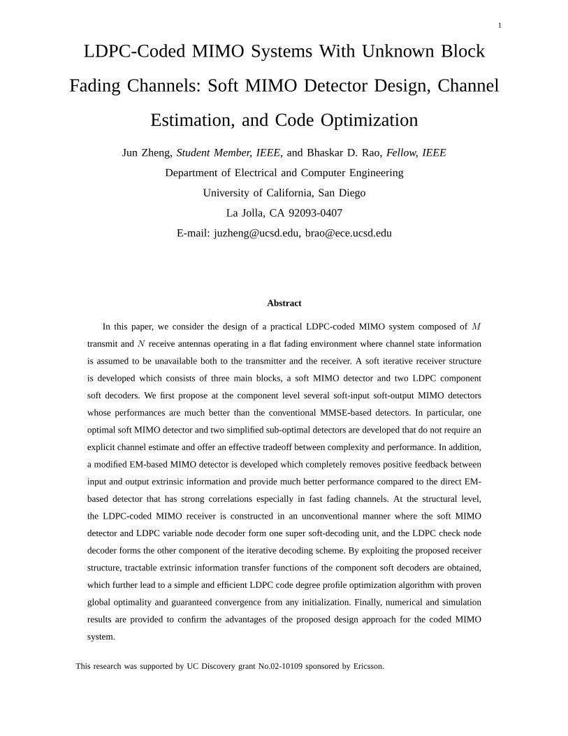
Fig. 1. Transmitter model of LDPC-coded MIMO systems
and receive antenna pair. As illustrated in Fig. 1, a block ofk binary information bits denotedd =
{d1, · · · , dk} is first encoded by an outer LDPC encoder with code rateRouter = k/n into a codeword
c = {c1, · · · , cn} of lengthn. The codewordc is further segmented intoL consecutive sub-blocksCi of
lengthK. Each sub-blockCi is then encoded by the inner space-time encoder into a coherent space-time
sub-frameXi. This encoder is composed of an interleaver, modulator, serial-to-parallel converter, and a
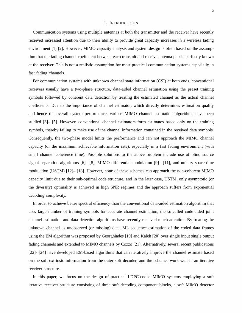
pilot insertion operator. The symbol structure of each sub-frameXi is illustrated in Fig. 2, where the first
Fig. 2. Transmitted symbol structure of the coded MIMO system
p symbols are training pilots, followed by(TM − p) data symbols. For the sake of simplicity, we only
consider the case where both the number of pilot symbols(p = Tτ ×M
)and the number of data symbols
(TM − p = Td × M
)are multiples of the transmit antenna numberM . We further denote the average
signal to noise ratio (SNR) of pilot symbols byρτ and data symbols byρd. Hence, the transmitted signal
Page 5
5
Xi can be partitioned into two sub-matrices: training followed by data, which is represented as
Xi =
(ρτ/M
) 1
2 · Xτ
(ρd/M
) 1
2 · Xd, i
, (1)
whereXτ ∈ CTτ×M are the fixed pilot symbols sent overTτ time intervals, andXd, i ∈ C
Td×M are the
information bearing data symbols sent overTd transmission intervals. Each element of the transmitted
data signalXd, i is a member of a finite complex alphabetX of size |X |. One entire MIMO codeword
X consists ofl = LTM complex symbols, which are transmitted fromM transmit antennas and across
L consecutive coherent sub-frames of lengthTM symbols.
It is assumed that the fading coefficient matrixHi remains static within each coherent sub-block and
varies independently from one sub-block to another. Hence,the signal model can be written as
Yi = Xi · Hi + wi, 1 ≤ i ≤ L , (2)
whereYi is aT ×N received complex signal matrix,Xi is aT ×M transmitted complex signal matrix,
Hi is an M × N complex channel matrix, andwi is a T × N matrix of additive noise matrix. Both
matricesHi andwi are assumed to have zero mean unit variance independent complex Gaussian entries.
We also assume that the entries of the transmitted signal matrix Xi have, on average, the following power
constraint,1
T· E
[tr
(XH
i Xi
)]= ρ . (3)
whereρ is the average signal to noise ratio at each receive antenna.Conservation of time and energy
leads to the following constraints,
tr(XH
τ · Xτ
)= MTτ , EXd, i
[tr
(XH
d, i · Xd, i
)]= MTd ,
T = Tτ + Td, ρT = ρτTτ + ρdTd . (4)
Due to the insignificant capacity gain resulting from using optimal power allocation between training and
data symbols as reported in [28] [29], equal power allocation is assumed in this paper, with
ρτ = ρd = ρ . (5)
B. MIMO receiver structure
The MIMO receiver decodes the transmitted information bitsd based on received signal matrices{Yi
}L
i=1without knowing any instantaneous channel state information
{Hi
}L
i=1. The channel statistical
distributionp(Hi
)is assumed to be known both to the receiver and to the transmitter throughout the paper.
We know that even with ideal CSI, the optimal decoding algorithm for this system has an exponential
Page 6
6
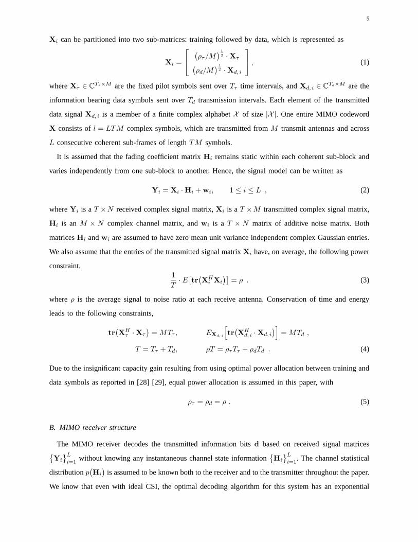
Fig. 3. Conventional receiver structure of LDPC-coded MIMO systems
complexity. Hence the near-optimal iterative receiver structure based on turbo principle [26] becomes a
promising alternative.
As a standard iterative decoding procedure, the structure of the LDPC-coded MIMO receiver is
demonstrated in Fig. 3. It consists of two important components, an inner soft-input soft-output MIMO
detector (or MIMO demodulator) and an outer soft LDPC decoder,which form a bipartite graph structure
[30]. Soft log likelihood ratio of each transmitted bit is passed forward and backward between these two
soft decoders with increasing accuracy as the number of the iterations increase. At each iteration, the
MIMO detector forms soft extrinsic information of each coded bit based on the received symbols{Yi
}L
i=1
and the apriori information coming from the soft LDPC decoder through proper interleaving, and serves
as the apriori information for the LDPC decoder in the next iteration. Convergence is reached after certain
number of the iterations and decoded bits are hence obtained.
Notice that the LDPC decoder in Fig. 3 is itself composed of two component soft decoders (variable
node decoder and check node decoder), and the entire MIMO receiver can be viewed as a complicated
graph code structure. Therefore, any bipartite separation other than the conventional structure can lead to
an alternative iterative decoder. We utilize in Section IV-Aan unconventional MIMO receiver structure,
which combines the soft MIMO detector and LDPC variable node decoder together as a super component
soft-decoder. The proposed receiver structure has great design advantages that can easily lead to an
efficient LDPC code degree profile optimization algorithm as shown in Section IV-C.
III. SOFT-INPUT SOFT-OUTPUT MIMO D ETECTOR
As described in Section II-B, the soft-input soft-output MIMO detector is an important decoding
component of the MIMO receiver, and plays an important role in determining the performance of the
entire coded MIMO system. Regular communication systems with unknown channel state information
typically employ a two-stage decoding procedure, which consists of channel estimation followed by
coherent decoding based on the estimated channel parameters. However, conventional channel estimators
perform estimation based only on the training pilots, thereby failing to make use of the channel information
contained in the data symbols. Due to the mismatch between the actual and estimated channel, system
Page 7
7
performance suffers severe degradation especially in a communication environment with low signal to
noise ratio, or limited training pilots in fast fading channels.
In this section, several better MIMO detectors which include the soft MIMO detector, EM-based MIMO
detector, as well as their modified versions are proposed thatoffer an effective tradeoff between detection
complexity and performance. The MIMO detection algorithms proposed in this section are block-based
in the sense that the data detections are performed within each coherent fading block. By considering
the channel coefficient correlations between adjacent coherent blocks, one could achieve even better
performance by performing data detection on several adjacent coherent blocks together. In this case, the
data detection algorithm has higher computational complexity and depends heavily on the correlations of
the fading channel, and is beyond the scope of this paper. Therefore for simplicity, it is reasonable to use
a block fading channel model in this situation and the performance penalty of the simple block-based
MIMO detection algorithm would be small by properly tuning the channel coherence timeT according
to the actual channel correlations.
For the sake of simplicity, subscript (or time index)i, denoting theith coherent block, is dropped in
this section while describing the block-wise soft MIMO detection algorithms. To be specific, we denote
X =[XT
τ , XTd
]T, H, and Y =
[YT
τ , YTd
]Tas the transmitted signal, channel matrix, and received
signal in each coherent block, respectively. Furthermore, sub-matricesXτ , Xd, Yτ , and Yd have the
following structures, i.e.
Xτ =[xT
τ,1, · · · ,xTτ,Tτ
]T
, Xd =[xT
d,1, · · · ,xTd,Td
]T
, xτ,k
∣∣Tτ
k=1, xd,k
∣∣Td
k=1∈ C
1×M ,
Yτ =[yT
τ,1, · · · ,yTτ,Tτ
]T
, Yd =[yT
d,1, · · · ,yTd,Td
]T
, yτ,k
∣∣Tτ
k=1, yd,k
∣∣Td
k=1∈ C
1×M . (6)
Similarly, the binary sub-codewordC that maps to the transmitted signalX can also be decomposed into
C =[cT1 , · · · , cT
Td
]T
, ck
∣∣Td
k=1∈ B
1×M · log2 |X | , (7)
whereB is binary set{0, 1} and each rowck represents the corresponding binary information that maps
to xd,k.
A. Optimal soft MIMO detector
First, according to the channel model (2), the conditional probability density of the received signal
matrix Y given the transmitted signal matrixX is given by [31]
p(Y
∣∣X)
=
exp
(− tr
{[IT + XXH
]−1· YYH
})
πTN detN[IT + XXH
] . (8)
Page 8
8
It is evident from the above transitional probability that the unknown MIMO channel is actually a
memoryless vector channel and hence the optimal MIMO detector does not necessarily need to form a
specific channel estimate.
In order to obtain the a posteriori probability of each codedbit, the a priori probability of the input
signal matrixX is first calculated as
p(X
)= p
(Xd
)= p(C) =
Td∏
k=1
p(xk) =
Td∏
k=1
p(ck) =
Td∏
k=1
M log2 |X |∏
j=1
p(ck,j) , (9)
where each element of matrixXd is a member of a complex alphabetX of size |X |, and corresponding
to log2 |X | LDPC-coded bits. Therefore, the log likelihood ratio of each LDPCcoded bit is given by
Lpos(ck,j) = log
(p(ck,j = 1
∣∣Y)
p(ck,j = 0
∣∣Y))
= log
(Σ
X∈D+k,j
p(Y
∣∣X)· p
(X
)
ΣX∈D−
k,jp(Y
∣∣X)· p
(X
)
), 1 ≤ k ≤ Td, 1 ≤ j ≤ M · log2 |X | , (10)
whereD+k,j (D−
k,j) is the set ofX for which the (k, j)th bit ck,j of the LDPC coded sub-blockC is
“ + 1” (“ − 1”). Finally, by subtracting the input a priori information from the obtained a posterior log
likelihood ratio, the soft extrinsic information of each coded bit is obtained as
Lext(ck,j) = Lpos(ck,j) − Lapp(ck,j), Lapp(ck,j) = log(p
(ck,j = 1
)
p(ck,j = 0
))
, (11)
whereLapp(ck,j) is the a priori information of the coded bitck,j from the last iteration. Notice that there
is no channel estimation stage in the soft MIMO detector described above, and therefore the proposed
detection algorithm does not depend on the unknown channel stateH but only on its underlying statistical
distribution. Furthermore, the optimality of the proposed soft MIMO detection algorithm is restricted
within the component level and does not depend on the overallreceiver structure of the coded-MIMO
system.
B. Sub-optimal soft MIMO detector
The optimal soft MIMO detection algorithm proposed in SectionIII-A provides the optimal extrinsic
LLR values of each coded bit. However, the summation in both thenumerator and the denominator of
equation (10) consists of2K−1 items, withK(=TdM log2 |X |
)increasing linearly with number of data
slotsTd (or coherence timeT ). It has an unaffordable exponential complexity for practical communication
systems, especially when the coherence timeT is large. Hence, we propose a sub-optimal MIMO detector
in this section with complexity increasing linearly withTd.
Notice that the optimal extrinsic LLR value of bitck,j depends on the input a priori information as
well as the channel observations of the entire coherent block. Taking another point of view, the obtained
Page 9
9
DET
DET
. . . . . .
−
Xτ Xτxd,1 xd,2 xd,Td
xd,k
xd,k′
Lext-p(ck,j)
Lext-p(ck,j) Lext-d,2(ck,j) Lext-d,Td(ck,j)
Lext,k′(ck,j)
Lext-d(ck,j)
Lext(ck,j)Σ
Σ
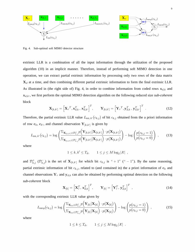
Fig. 4. Sub-optimal soft MIMO detector structure
extrinsic LLR is a combination of all the input information through the utilization of the proposed
algorithm (10) in an implicit manner. Therefore, instead of performing soft MIMO detection in one
operation, we can extract partial extrinsic information byprocessing only two rows of the data matrix
Xd at a time, and then combining different partial extrinsic information to form the final extrinsic LLR.
As illustrated in (the right side of) Fig. 4, in order to combine information from coded rowsxd,k and
xd,k′ , we first perform the optimal MIMO detection algorithm on the following reduced sizesub-coherent
block
X[k,k′] =[Xτ
T ,xTd,k , xT
d,k′
]T
, Y[k,k′] =[Yτ
T ,yTd,k , yT
d,k′
]T
. (12)
Therefore, the partial extrinsic LLR valueLext, k′
(ck,j
)of bit ck,j obtained from the a priori information
of row ck, ck′ , and channel observationY[k,k′] is given by
Lext, k′
(ck,j
)= log
(Σ
X[k,k′]∈D+k,j
p(Y[k,k′]
∣∣X[k,k′]
)· p
(X[k,k′]
)
ΣX[k,k′]∈D
−
k,jp(Y[k,k′]
∣∣X[k,k′]
)· p
(X[k,k′]
)
)− log
(p(ck,j = 1
)
p(ck,j = 0
))
, (13)
where
1 ≤ k, k′ ≤ Td, 1 ≤ j ≤ M log2 |X | ,
and D+k,j (D−
k,j) is the set ofX[k,k′] for which bit ck,j is “ + 1” (“ − 1”). By the same reasoning,
partial extrinsic information of bitck,j , related to (and contained in) the a priori information ofck and
channel observationsYτ andyd,k can also be obtained by performing optimal detection on the following
sub-coherentblock
X[k] =[XT
τ , xTd,k
]T
, Y[k] =[YT
τ , yTd,k
]T
, (14)
with the corresponding extrinsic LLR value given by
Lext-p(ck,j
)= log
(Σ
X[k]∈D+k,j
p(Y[k]
∣∣X[k]
)· p
(X[k]
)
ΣX[k]∈D
−
k,jp(Y[k]
∣∣X[k]
)· p
(X[k]
)
)− log
(p(ck,j = 1
)
p(ck,j = 0
))
, (15)
where
1 ≤ k ≤ Td, 1 ≤ j ≤ M log2 |X | .
Page 10
10
Having obtained extrinsic informationLext, k′
(ck,j
)and Lext-p
(ck,j
), one can obtain by the following
substraction,
Lext-d, k′
(ck,j
)= Lext, k′
(ck,j
)− Lext-p
(ck,j
), (16)
the extrinsic information of bitck,j extracted solely from the channel observationyd,k′ and the a priori
information ofck′ . In contrast to the situation of perfect channel state information at the receiver (CSIR)
whereLext(ck,j) only depends on the a priori knowledge ofck and observationyd,k, a non-zero extrinsic
information ofck,j can be obtained from the a priori knowledge ofck′ and observationyk′ (with k′ 6= k)
in an unknown MIMO fading environment. An intuitive explanation of the above difference can be made
by viewingck′ as partially fixed pilots based on the input a priori information. Therefore, better channel
knowledge is learned (although no explicit channel estimation exists), which translates into a better a
posterior probability ofck,j . Hence, a non-zero partial extrinsic information solely from the a priori
probability of ck′ and the channel observationyk′ is obtained.
Due to the assumption that the input a priori information of different bits are independent, all the
partial extrinsic informationLext-d,k′(ck,j) andLext-p(ck,j) can be viewed as being close to independent.
As illustrated in (the left side of) Fig. 4, the final output extrinsic informationLext(ck,j) is obtained by
summing all the independent partial extrinsic informationobtained from different coded rowsck′ and
pilot observations, i.e.
Lext(ck,j
)=
Td∑
k′=1k′ 6=k
Lext-d, k′
(ck,j
)+ Lext-p
(ck,j
)=
Td∑
k′=1k′ 6=k
Lext, k′
(ck,j
)− (Td − 2) · Lext-p
(ck,j
), (17)
where
1 ≤ k ≤ Td, 1 ≤ j ≤ M log2 |X | .
A summation of22M log2 |X | terms is required to extract the partial extrinsic information Lext,k′(ck,j)
in equation (13) and2M log2 |X | terms forLext-p(ck,j) in equation (15). Therefore, in order to obtain the
output soft extrinsic LLR values, a total number of((Td−1)·22M log2 |X |+2M log2 |X |
)terms of probability
summation is required for each coded bit, as opposed to2TdM log2 |X | terms in the original optimal soft
MIMO detector. Furthermore, the proposed sub-optimal soft MIMO detection algorithm can be easily
generalized by extracting partial extrinsic information through combining more than two (E in general)
rows of the sub-codewordC together. By choosing different combination size of2 ≤ E ≤ Td, a group
of sub-optimal MIMO detectors can be constructed which offer a varying degree of detection complexity
to system performance tradeoff.
Page 11
11
−DET
DET
XτXτ
xd,k
xd,k xd,k
xd,k′
xd,k′
Lext-p(ck,j)
Lext-p(ck,j)
Lnext-d(ck,j) Ln
ext-d(ck′,j)
∆Ln+1ext-d(ck′,j)
∆Ln+1ext-d(ck,j) ∆Ln+1
ext-d(ck,j)
Ln+1ext-d(ck,j) Ln+1
ext-d(ck′,j)
Lmext-d(ck,j)
Lext(ck,j)
Ln+1ext (ck,j)
Ln+1app (ck′,j) = Ln
ext-d(ck′,j) + Lapp(ck′,j)
ΣΣ Σ
Σ
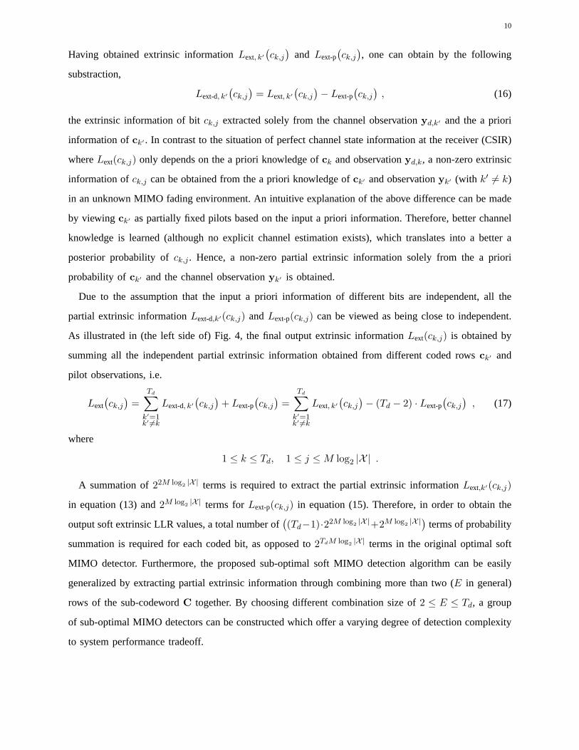
Fig. 5. Sub-optimal soft MIMO detector using butterfly structure
C. Sub-optimal butterfly soft MIMO detector
Motivated by the fast Fourier transform (FFT) algorithm, we canfurther reduce the complexity of the
soft MIMO detector to(log2 Td · 22M log2 |X | + 2M log2 |X |
)terms of summation per coded bit by using a
sub-optimal butterfly MIMO detector structure as illustrated in Fig. 5. It is first assumed that the number
of the data slotsTd = 2m, a power of2. If not, we can appropriately zero-pad the transmitted signal
matrix X. As demonstrated in (the left part of) Fig. 5, the sub-optimalbutterfly detection algorithm
obtains the extrinsic information through a multi-level structure similar to the fast Fourier transform,
where the extrinsic information is accumulated from level to level. Specifically, if the partial extrinsic
LLR value of coded bitck,j at thenth level is Lnext-d
(ck,j
), then the extrinsic LLR value of the(n + 1)th
level can be updated by the following form, which is illustrated in (the right part of) of Fig. 5,
Ln+1ext-d
(ck,j
)= Ln
ext-d
(ck,j
)+ ∆Ln+1
ext-d
(ck,j
), 0 ≤ n ≤ m − 1 , (18)
where the second term∆Ln+1ext-d
(ck,j
)of equation (18) represents the additional partial extrinsic information
obtained from the information of coded bitsck′ , with sub-codeword row indexk′ given by
k′ =
k + 2m−n−1 if k (mod 2m−n
)< 2m−n−1
k − 2m−n−1 if k (mod 2m−n)≥ 2m−n−1
. (19)
Similar to the extraction algorithm provided in (16),∆Ln+1ext-d
(ck,j
)is given by the following form
∆Ln+1ext-d
(ck,j
)= Ln+1
ext
(ck,j
)− Lext-p
(ck,j
), (20)
whereLext-p(ck,j
)is given by equation (15), and partial extrinsic information Ln+1
ext
(ck,j
)is obtained by
performing optimal soft MIMO detection on the sub-coherentblock X[k,k′] and Y[k,k′] with modified
input a priori information, i.e.
Ln+1ext
(ck,j
)= log
(Σ
X[k,k′]∈D+k,j
p(Y[k,k′]
∣∣X[k,k′]
)· pn+1
app
(X[k,k′]
)
ΣX[k,k′]∈D
−
k,jp(Y[k,k′]
∣∣X[k,k′]
)· pn+1
app(X[k,k′]
)
)− log
(p(ck,j = 1
)
p(ck,j = 0
))
. (21)
Furthermore, the modified a priori probabilitypn+1app
(X[k,k′]
)in equation (21) is a combination of the
a priori probability ofck and ck′ as well as thenth level extrinsic information ofck′ , which can be
Page 12
12
represented as
pn+1app
(X[k,k′]
)= p
(ck
)· p
(ck′
)· pn
ext
(ck′
)=
M log2 |X |∏
j=1
p(ck,j
)· p
(ck′,j
)· pn
ext
(ck′,j
), (22)
wherepnext
(ck′,j
)is given by
pnext
(ck′,j
)=
exp(ck′,j · Ln
ext-d
(ck′,j
))
1 + exp(Ln
ext-d
(ck′,j
)) . (23)
Therefore,∆Ln+1ext-d
(ck,j
)can be viewed as the partial extrinsic information obtainedsolely from the a
priori information ofck′ , channel observationyk′ , and its extrinsic information at thenth level.
Starting from the initial conditionL0ext-d(ck,j) = 0, the extrinsic informationLn
ext-d(ck,j) of each coded
bit is accumulated at each level by absorbing additional partial extrinsic information through the sub-
coherent block combining process. As illustrated in (the middle part of) Fig. 5, the final soft extrinsic
LLR value of each coded bit is formed by combining the extrinsicLLR information at themth (lowest)
level with the extrinsic information obtained from pilot observations, which is given by
Lext(ck,j
)= Lm
ext-d
(ck,j
)+ Lext-p
(ck,j
)1 ≤ k ≤ Td, 1 ≤ j ≤ M log2 |X | . (24)
Note that both the sub-optimal structure in Section III-B as well as the sub-optimal butterfly MIMO
detector in the previous subsection are modifications of the optimal soft MIMO detection algorithm
provided in Section III-A. The two sub-optimal MIMO detectionalgorithms provided in Section III-B
and III-C have the following structural differences. First,the sub-optimal MIMO detector in Section III-B
forms extrinsic information through alinear combining structure, where there are a total of(Td − 1)
partial extrinsic information terms (each corresponding to the partial extrinsic LLR obtained from other
rows k′); each term is computed by performing optimal detection on the sub-coherent block given by
(13)-(16). On the other hand, the sub-optimal butterfly MIMO detector in Section III-C performs data
detection by employing a multi-level structure, where the extrinsic information is distributed at succeeding
levels until all the input a priori information and the channel observations are combined and exchanged
between all different rows.
D. Modified EM-based MIMO detector
The soft MIMO detector and its two sub-optimal modifications proposed in previous sections perform
data detection without forming any specific channel estimate. However, forming a channel estimation
followed by coherent MIMO detection is in some cases a promising alternative especially when there
are enough training pilots. Besides, the estimated channelstate informationH can be easily fedback to
the transmitter for better power allocation and spectral shaping of the channel coding.
Page 13
13
Recently, a lot of attention has been focused on turbo MAP EM estimators, which can take into account
not only the training pilots but also the a priori information of the coded bits from the outer soft LDPC
decoder. As reported in [23] [24], the proposed turbo EM estimator provides better performance than the
conventional MMSE-based channel estimator and works well in an iterative decoding algorithm, especially
whenTd is large. However, there exists positive feedback between the input and output soft LLR values
which can cause severe performance degradation of the codedMIMO system. Therefore, we propose
in this section a modified EM-based MIMO detector that avoids positive feedback and results in better
performance than the direct EM-based detection algorithm. Mutual information transfer characteristic of
the modified EM-based detector as well as the corresponding simulation results provided in Section IV
and V further confirm our claims of superiority of the new detector.
To start with the detection algorithm, let us first look at the conventional MAP EM estimator, whose
objective is to find the channel estimationH that maximizes a posterior probability
H = arg maxH
p(H
∣∣Y)
= arg maxH
p(Y ,H
), (25)
which is intractable by direct maximization. Hence by taking the transmitted data signal matrixXd (or
X) as the unobserved (or missing) data, the following iterative expectation maximization (EM) algorithm
(similar to [23]) is applied .
• E-step:
Q(H
∣∣H(n))
= EX
∣∣H(n),Y
[− log p
(H,Y
∣∣X)]
. (26)
After some manipulations, we have the following concise form
Q(H
∣∣H(n))
= EX
∣∣H(n),Y
[tr
(HHH +
(Y − XH
)H(Y − XH
))]
= tr(HHR H + YHY −
(YHUH + HHUHY
)), (27)
whereR is given by
R = EX
∣∣H(n),Y
[XHX
]+ IM
=ρ
M·( Td∑
j=1
∑
xd,k∈XM
p(xd,k
∣∣H(n),yd,k
)· xH
d,k xd,k + XHτ Xτ
)+ IM , (28)
andU is given by
U = EX
∣∣H(n),Y
[X
]=
√ρ
M·[XT
τ , µT1 , · · · , µT
Td
]T
, µk =∑
xd,k∈XM
p(xd,k
∣∣H(n),yd,k
)·xd,k .
(29)
The a posterior probabilityp(xd,k
∣∣H(n),yd,k
)is given by
p(xd,k
∣∣H(n),yd,k
)=
p(yd,k
∣∣H(n),xd,k
)· p
(xd,k
)∑
xd,k∈XM p(yd,k
∣∣H(n),xd,k
)· p
(xd,k
) , (30)
Page 14
14
with p(yd,k
∣∣H(n),xd,k
)andp
(xd,k
)given as
p(yd,k
∣∣H(n),xd,k
)=
1
πNexp
(−
∥∥yd,k −√
ρ
M· H(n)xd,k
)∥∥2)
, (31)
wherep(xd,k
)is given by
p(xd,k
)=
M log2 |X |∏
j=1
p(ck,j
). (32)
• M-step:
H(n+1) = arg minH
Q(H
∣∣H(n))
. (33)
After some manipulations, the updated channel estimationH(n+1) is obtained as
H(n+1) = R−1 · UH · Y . (34)
• Initialization:
We use the conventional minimal mean square error (MMSE) channel estimator for initialization,
which is given by
H(0) =
√ρ
M· XH
τ ·( ρ
MXτX
Hτ + ITτ
)−1 · Yτ . (35)
Since the EM iteration is embedded within the large iterative decoding loop of the soft MIMO
receiver, we can also take the estimated channelH from the last decoding iteration as an EM
initialization. Compared with the simple MMSE estimator, the obtained estimation from the last
decoding iteration (through an EM algorithm) provides a better initialization since additional a
priori information of the coded bits is used. Therefore, by using the alternative initialization, EM
algorithm is able to begin at a better starting point and hence results in smaller number of EM
iterations.
Maximum a posterior channel estimation is obtained when theMAP EM algorithm converge toH
after certain number of iterations. Hence the soft extrinsic information of each coded bitck,j is provided
by takingH as the true channel coefficients followed by coherent MIMO detection,
Lext(ck,j
)= log
(Σ
xd,k∈D+k,j
p(yd,k
∣∣H,xd,k
)· p
(xd,k
)
Σxd,k∈D
−
k,jp(yd,k
∣∣H,xd,k
)· p
(xd,k
)
)− log
(p(ck,j = 1
)
p(ck,j = 0
))
, (36)
where
1 ≤ k ≤ Td, 1 ≤ j ≤ M log2 |X | .
D+k,j (D−
k,j) is the set ofxd,k for which bit ck,j is “+1” (“− 1”), and probabilitiesp(yd,k
∣∣H,xd,k
)and
p(xd,k
)are given by (31) and (32) respectively.
Page 15
15
It is well known that short girth in the LDPC Tanner graph is one of the major performance bottleneck
for short length LDPC code design [32] [33], where positive feedback of the iterative LLR values
generated by the existing short length loops directly affects the iterative message passing algorithm.
Similarly, positive feedback caused by the correlations between input and output extrinsic information
of the MIMO detector will also cause severe system performance degradation. Therefore, considerable
effort has been made in various detection algorithms to avoid the same information from counting twice,
or to avoid the output extrinsic LLR values from containing anyinput a priori information.
Unfortunately, if we study the conventional direct EM-basedsoft MIMO detection algorithm carefully,
we will find that the estimated channel coefficient does depend on the a priori information of the entire
sub-codewordC. To be specific, channel estimationH can be represented as a function given by
H = H(Y,AL-app
), (37)
whereAL-app ∈ RTd×M log2 |X | is the a priori information matrix with each elementak,j equal to the a
priori LLR value Lapp(ck,j). Therefore, the extrinsic information obtained by equation(36) contains the
input a priori information throughH, in a sense thatLext(ck,j) depends onLapp(ck,j), even though the a
priori LLR value is already subtracted from the log a posteriorvalue as demonstrated by the second term.
In order to eliminate input-output correlations introduced by the direct channel estimationH, which is
a function ofLapp(ck,j
), we propose a modified EM channel estimation algorithm that uses only part of
the a priori information (a subset of matrixAL-app) of the sub-codewordC. If we denoteE as a subset
of {1, 2, · · · , Td} that includesk, the partial a priori information matrix can be formed by thefollowing
weighting operation
AEL-app = diag
(s)· AL-app , (38)
where the selecting vectors of size1 × Td is given by
s =[s1, s2, · · · , sTd
], sj =
1 if j /∈ E0 if j ∈ E
. (39)
The modified channel estimation is hence obtained by applying the same APP EM algorithm by using
AEL-app as the input a priori information matrix instead, i.e.
HE = H(Y,AE
L-app
). (40)
The modified estimationHE can therefore be used to perform coherent detections for coded rowsck
with index k ∈ E ,
Lext(ck,j
)= log
(Σ
xd,k∈D+k,j
p(yd,k
∣∣HE ,xd,k
)· p
(xd,k
)
Σxd,k∈D
−
k,jp(yd,k
∣∣HE ,xd,k
)· p
(xd,k
)
)− log
(p(ck,j = 1
)
p(ck,j = 0
))
, k ∈ E . (41)
Page 16
16
Let us further assume that the entire set{1, 2, · · · , Td} can be decomposed into the following disjoint
sets with the same size, i.e.
{1, 2, · · · , Td} =⋃
n
En, En
⋂En′ = φ,
∣∣En
∣∣ = SE . (42)
Instead of having only one EM estimation in the direct EM-baseddetector,⌈Td/SE⌉ separate EM
estimations are to be completed during one entire soft decoding iteration in the modified EM-based
detector. Note thatEn = {n} and En = φ correspond to special cases:En = {n} has the maximum
detection complexity, but takes into account all availablea priori information from the outer soft decoder,
while on the other handEn = φ corresponds to the case of conventional direct EM-based detection
algorithm. For a short complexity analysis, we know that within each EM estimation, there are total
NEMsum = I ·
(3Td ·2M log2 |X |
)summation operations, whereI is the average number of iterations required
by the convergence of the EM algorithm. Therefore, the averagenumber of the summations for each
coded bit in the modified EM-based MIMO detector is
NDECsum =
(3I ·
⌈Td/SE
⌉+ 1
)· 2M log2 |X | . (43)
The EM channel estimation algorithms proposed in this sectioncan make full use of the soft a priori
information of the coded bits from the outer LDPC decoder, and hence provide better (and more accurate)
channel estimations. From another point of view, the MAP EM estimator is generally equivalent to
extending the pilot structure to the entire transmitted signal matrix X. Instead of limiting the pilots to
Xτ , the receiver treatsXd as partially fixed pilots as well especially when the LLR ratios are getting
significantly improved as a result of the messages being updated constantly through the iterations.
Finally, a brief comparison of the pilots size required by thedifferent MIMO detection algorithms is
as follow. First, we note that the proposed optimal soft MIMO detector as well as its two sub-optimal
modifications are able to provide soft data detections with arbitrary number of pilot symbols and only
need a small number of pilots in order to remove detection ambiguity (in the first decoding iteration).
The modified EM-based detector only requires a small number (Tτ ≥ M ) of pilots for the initialization
of the EM estimation. Therefore, these four soft MIMO detection algorithms provide a wide range of
trade-offs between complexity and performance and can workin different MIMO fading environments
and support various training sizes.
IV. D ESIGN OFLDPC-CODED MIMO SYSTEMS
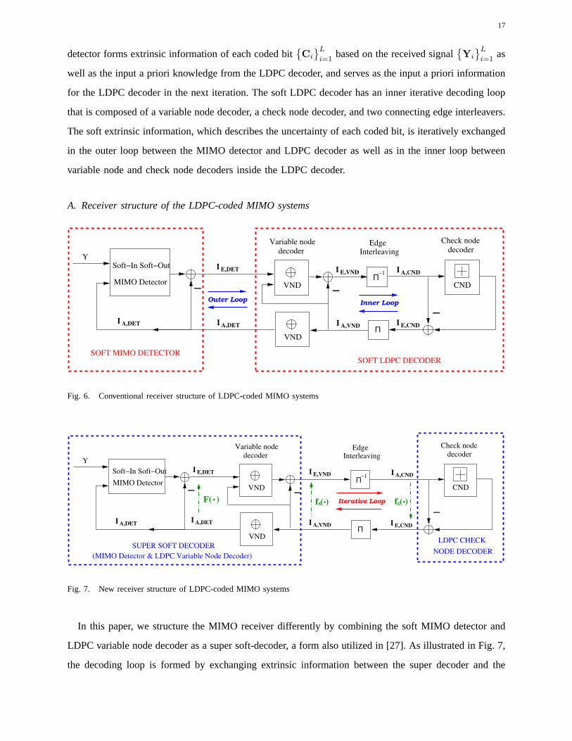
Conventionally the coded MIMO receiver is obtained by connecting the inner soft MIMO detector and
the outer LDPC decoder to form one large iterative decoding loop. As evident from Fig. 6, the overall
MIMO receiver actually consists of two iterative decoding loops. In the outer loop, the soft MIMO
Page 17
17
detector forms extrinsic information of each coded bit{Ci
}L
i=1based on the received signal
{Yi
}L
i=1as
well as the input a priori knowledge from the LDPC decoder, and serves as the input a priori information
for the LDPC decoder in the next iteration. The soft LDPC decoder has an inner iterative decoding loop
that is composed of a variable node decoder, a check node decoder, and two connecting edge interleavers.
The soft extrinsic information, which describes the uncertainty of each coded bit, is iteratively exchanged
in the outer loop between the MIMO detector and LDPC decoder as well as in the inner loop between
variable node and check node decoders inside the LDPC decoder.
A. Receiver structure of the LDPC-coded MIMO systems
Inner Loop
−1
EdgeInterleaving
Π
VND
decoder
Variable node
VND
−
I E,VND
I A,VND
decoder
Check node
E,CNDI
A,CNDI
I A,DET
I E,DET
I A,DET
SOFT LDPC DECODER
CND
−
−
Y
SOFT MIMO DETECTOR
Soft−In Soft−Out
MIMO Detector
Outer Loop
Π
Fig. 6. Conventional receiver structure of LDPC-coded MIMO systems
−
−1
EdgeInterleaving
Π
VND
decoder
Variable node
VND
MIMO Detector
Soft−In Soft−Out
I A,DET
I E,DET
I A,DET
F( ).
I E,VND
I A,VND
.f ( )s
decoder
Check node
E,CNDI
A,CNDI
.f ( )cIterative Loop−
SUPER SOFT DECODER
(MIMO Detector & LDPC Variable Node Decoder)
−
Y
CND
NODE DECODER
LDPC CHECK
Π
Fig. 7. New receiver structure of LDPC-coded MIMO systems
In this paper, we structure the MIMO receiver differently bycombining the soft MIMO detector and
LDPC variable node decoder as a super soft-decoder, a form alsoutilized in [27]. As illustrated in Fig. 7,
the decoding loop is formed by exchanging extrinsic information between the super decoder and the
Page 18
18
LDPC check node decoder iteratively. Compared with the conventional iterative MIMO receiver (named
as bit-interleaved coded modulation with iterative decoding (BICM-ID) algorithm) shown in Fig. 6, the
new receiver structure has two advantages. First, the proposed receiver structure has only one iterative
decoding loop and hence achieves smaller decoding complexity compared to the two iterative loops (inner
LDPC decoder loop and outer “MIMO detector⇄ LDPC decoder” loop) in the conventional BICM-ID
structure. Second, the proposed structure has the advantageof enabling the extrinsic information transfer
characteristic function of the soft component decoders to have tractable forms. By fully exploiting the
closed form EXIT functions, a simple and efficient LDPC code degree profile optimization algorithm
with proven global optimality and guaranteed convergence is proposed in Section IV-C, which is superior
to the sub-optimal manual curve fitting technique [25] [27].
B. Analysis of extrinsic information transfer characteristics
In order to understand as well as design the iterative decoding systems having bipartite graph structures,
we use the extrinsic information transfer characteristic of the soft MIMO detector and LDPC decoder,
which was proposed by Brink in [25], to analyze the convergence behavior of the iterative decoding
schemes of the coded MIMO system.
1) Brief introduction on EXIT-chart
We briefly describe in this section the EXIT-chart technique proposed in [25]. For readers who are
familiar with the topic, please skip to Section IV-B-2 directly. The extrinsic information transfer
(EXIT) function is used to the describe the input-output (a priori information versus extrinsic
information) relations of the soft component decoders froman information theoretical perspective.
Taking the component soft decoders in Fig. 7 as an example, thecorresponding EXIT functions of
the super soft-decoder and LDPC check node decoder can be described by the following mapping
(also depicted in Fig. 7 accordingly),
IE,VND = fs
(IA,VND
), IE,CND = fc
(IA,CND
), (44)
where IA,VND represents the mutual information between the coded bitx and the input a priori
information of the super soft-decoder, andIE,VND, IE,CND, as well asIA,CND are similarly defined.
According to the iterative decoding structure, where the output extrinsic information from one
component decoder is treated as a priori input to the other one, the mutual information between
the extrinsic LLR values and the coded bits is updated through the following evolution,
I kE,CND = fc ◦ fs
(I k−1
E,CND
), fc ◦ fs(·) = fc
(fs(·)
), (45)
Page 19
19
0 0.1 0.2 0.3 0.4 0.5 0.6 0.7 0.8 0.9 10
0.1
0.2
0.3
0.4
0.5
0.6
0.7
0.8
0.9
1
I A,VND
, I E,CND
I E,V
ND
, I A
,CN
D
Decoding Trajactory of a 2by2 LDPC−coded MIMO system, T=6, Tτ=2, and ρ=4dB
f s
(⋅): VND & MIMO DET EXIT Characteristic f
c −1(⋅): CND EXIT Characteristic
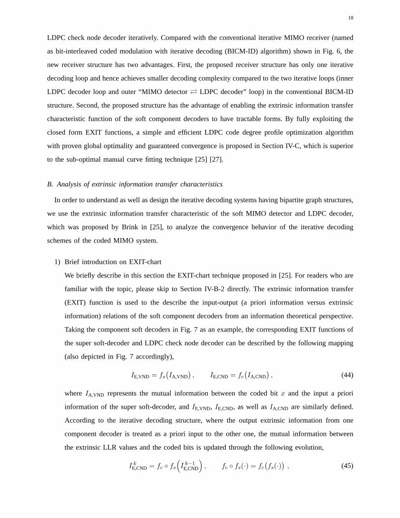
Fig. 8. Decoding trajectory of a regular(3, 6) LDPC-coded MIMO system with optimal soft MIMO detector over a2 × 2
unknown MIMO channel with coherence timeT = 6, training lengthTτ = 2, and signal to noise ratioρ = 4dB.
with index k indicating thekth decoding iteration and the initialization is given byI 0E,CND = 0. As
an example, we demonstrate in Fig. 8 the EXIT functionsfs andfc (with x and y axis flipped) of
the component soft decoders as well as the decoding trajectory of an LDPC-coded MIMO system.
The2×2 MIMO system considered has BPSK modulation, uses optimal softMIMO detector at the
receiver, and transmits over a fading channel with coherence timeT = 6, training numberTτ = 2,
and signal to noise ratioρ = 4dB. The outer LDPC code is a regular(3, 6) code with codeword
length8×104. We can observe from Fig. 8 that, as long as the EXIT chart curvefs is above curve
f−1c (with the x and y axis flipped), i.e.
fs(x) ≥ f−1c (x), 0 ≤ x ≤ 1 , (46)
the decoding trajectory is able to make its zigzag way until reaching the successful decoding point
(1, 1). Therefore, it can serve as a convergence criterion of the iterative decoding algorithm for the
LDPC code design purpose.
2) EXIT characteristic of the soft MIMO detector
According to the results provided in [25] [27], the extrinsic mutual informationIE,DET between the
transmitted bitx and the output LLR valuesLext(x), which measures the information contents of
Page 20
20
the output extrinsic LLR values, can be represented as
IE,DET(ρ; σ2A) = I
(Lext(x) ; x
)=
1
2
∑
x=±1
∫ ∞
−∞log2
( 2pE(ξ|x)
pE(ξ|x = +1) + p
E(ξ|x = −1)
)·p
E(ξ|x) dξ,
(47)
where distributionpE(ξ|x = ±1) is obtained through Monte Carlo simulation (histogram measure-
ments) by setting the system SNR equal toρ and the input a priori LLR values conditioned on the
transmitted bitx have a Gaussian distribution given by
Lapp(x) = x · n, x ∈ {+1,−1}, n ∼ N( 2
σ2A
.4
σ2A
)(48)
Therefore, the extrinsic mutual informationIE,DET depends both on the system SNRρ and the noise
variance levelσ2A of the input a priori information. By viewingρ as an index parameter, the EXIT
function of the soft MIMO detector is given by the following form
IE,DET = IE,DET
(ρ ; σ2
A = J−1(IA,DET))
, F∣∣ρ(IA,DET) , (49)
where functionJ(·) is given by (equivalent to equation (24) in the Appendix of [27]),
J(σ2
A
)= I
(Iapp(x) ; x
)=
1
ln 2
(1
σ2A
−∫ ∞
−∞
σA√2π
· ln cosh(y) ·exp(− (σ2
A · y − 1)2
2σ2A
)dy
). (50)
Furthermore, input mutual informationIA,DET of the soft MIMO detector is related to mutual
informationIA,VND through the following equation for a variable node of degreedv
IA,DET = J(dv · J−1
(IA,VND
)). (51)
3) EXIT characteristics of the LDPC variable node and check nodedecoders
Following the same reasoning as given in [27], the extrinsicmutual information transfer character-
istic of a variable node of degreedv is given by the following form
IE,VND
(IA,VND , dv
)= J
((dv − 1) · J−1(IA,VND) + J−1(IE,DET)
). (52)
According to the duality properties [34] of the EXIT curves between single parity check codes and
repetition codes over binary erasure channels, the mutual information transfer characteristic of a
degreedc check node over binary input Gaussian output channels can bewell approximated as
IE,CND(IA,VND) ≈ 1 − IE,REP(1 − IA,VND) = 1 − J((dc − 1) · J−1
(1 − IA,VND
)). (53)
Page 21
21
C. LDPC code optimization
Following the methodology given in [25] [27], the EXIT functions of the super MIMO soft-decoder
(combination of the LDPC variable node decoder and soft MIMO detector) can be obtained as
IE,VND = fs
(IA,VND
)=
Dv∑
i=1
λi · IE,VND
(IA,VND , dv, i
)
=
Dv∑
i=1
λi · J(
(dv, i − 1
)· J−1
(IA,VND
)+ J−1
(F
∣∣ρ
(J(dv, i · J−1
(IA,VND
)))). (54)
whereλi is the fraction of the variable nodes having edge degreedv, i, andDv is the number of different
variable node degrees. Similarly according to (53), the check nodes of the LDPC code have a transfer
characteristic given by the following form
IE,CND = fc
(IA,CND
)≈ 1 −
Dc∑
i=1
ρi · J((
dc, i − 1)· J−1
(1 − IA,CND
)), (55)
whereρi is the fraction of the check nodes having edge degreedc, i, andDc is the number of different
check node degrees.
Following the successful decoding (convergence) criterion provided in [25], the degree profile opti-
mization problem can be reduced to the following maximization problem by taking the LDPC code rate
Router as the objective
max{λi,ρi}
Router = max{λi,ρi}
(1 −
∑Dc
i=1 ρi/dc, i∑Dv
i=1 λi/dv, i
), (56)
under linear constraints given by
IE,VND(IA,VND) ≥ IA,CND(IE,CND) = IA,CND(IA,VND),Dv∑
i=1
λi = 1,
Dc∑
i=1
ρi = 1, 0 ≤ λi, ρi ≤ 1 . (57)
Utilizing the closed form EXIT functions of the component soft decoders given by (54) and (55), we
propose an efficient LDPC code degree profile optimization algorithm in the following, which is composed
of two simple linear optimization steps.
• Variable node degree profile optimization:
For a fixed check node degree profile{ρki } from thekth iteration, the optimal variable node degree
profile {λk+1i } is given by
{λk+1i } = arg max
{λi}
Dv∑
i=1
λi/dv, i , (58)
under the constraints
fs
(fc(an)
)≥ an ,
Dv∑
i=1
λi = 1, 0 ≤ λi ≤ 1, 1 ≤ n ≤ N, (59)
Page 22
22
where{an
∣∣an ∈ [0, 1]}
is a set of specified constraint points, andN is the total number of constraints
on the curve.
• Check node degree profile optimization:
For a fixed variable node degree profile{λk+1i } from the(k +1)th iteration, the optimal check node
degree profile{ρk+1i } is given by
{ρk+1i } = arg min
{ρi}
Dc∑
i=1
ρi/dc, i , (60)
under the constraints
fc
(fs(an)
)≥ an ,
Dv∑
i=1
ρi = 1, 0 ≤ ρi ≤ 1, 1 ≤ n ≤ N, (61)
wherean andN are similarly defined as before.
• Initialization:
In general, we can start with any feasible degree profiles. Based on our experience from numerical
simulations, we find that it is always a good choice to start with a regular check node degreedc.
If we stack the LDPC code degree profile{λi, ρi} into a super vectorη = [λ1, · · · , λDv
, ρ1, · · · , ρDc
]T .
We can see that the objectiveRouter given in equation (56) is a concave function with respect toη and
that all the constraints given in (57) are linear. Hence, theabove degree optimization problem has only
one unique optimal solution. Due to the non-decreasing property of the proposed iterative maximization
algorithm, it is guaranteed to converge to the global maximum solutionη⋆ from any initialization point.
Therefore, in contrast to the sub-optimal manual curving fitting technique proposed in [27], the above
iterative LDPC optimization algorithm provides much better performance and can serve as an efficient
tool for coded MIMO system design.
V. NUMERICAL AND SIMULATION RESULTS
A. Elimination of positive feedback in EM-based MIMO detectors
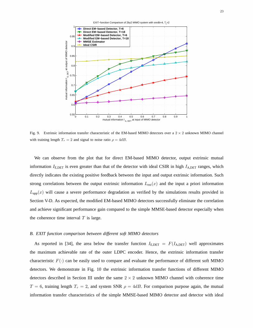
We demonstrate in Fig. 9 the extrinsic information transfer functions of the EM-based and modified
EM-based soft MIMO detectors over an unknown2 × 2 MIMO channel with coherence time interval
T = 6 and18, training lengthTτ = 2, and signal to noise ratioρ = 4dB. BPSK modulation is assumed
for all the simulation results in this section unless explicitly mentioned. For comparison purpose, the
mutual information transfer characteristics of the simpleMMSE-based MIMO detector and detector with
ideal CSIR are also included in the plot.
Page 23
23
0 0.1 0.2 0.3 0.4 0.5 0.6 0.7 0.8 0.9 10.55
0.6
0.65
0.7
0.75
0.8
0.85
0.9
0.95
1
EXIT−function Comparison of 2by2 MIMO system with snrdb=4, Tτ=2
mutual information I A, DET
at input of MIMO detector
mut
ual i
nfor
mat
ion
I E, D
ET a
t out
put o
f MIM
O d
etec
tor
Direct EM−based Detector, T=6Direct EM−based Detector, T=18Modified EM−based Detector, T=6Modified EM−based Detector, T=18MMSE EstimatorIdeal CSIR
Fig. 9. Extrinsic information transfer characteristic of the EM-based MIMO detectors over a2 × 2 unknown MIMO channel
with training lengthTτ = 2 and signal to noise ratioρ = 4dB.
We can observe from the plot that for direct EM-based MIMO detector, output extrinsic mutual
informationIE,DET is even greater than that of the detector with ideal CSIR in high IA,DET ranges, which
directly indicates the existing positive feedback betweenthe input and output extrinsic information. Such
strong correlations between the output extrinsic information Lext(x) and the input a priori information
Lapp(x) will cause a severe performance degradation as verified by thesimulations results provided in
Section V-D. As expected, the modified EM-based MIMO detectors successfully eliminate the correlation
and achieve significant performance gain compared to the simple MMSE-based detector especially when
the coherence time intervalT is large.
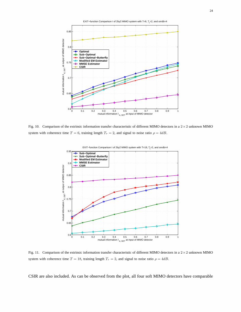
B. EXIT function comparison between different soft MIMO detectors
As reported in [34], the area below the transfer functionIE,DET = F (IA,DET) well approximates
the maximum achievable rate of the outer LDPC encoder. Hence, the extrinsic information transfer
characteristicF (·) can be easily used to compare and evaluate the performance ofdifferent soft MIMO
detectors. We demonstrate in Fig. 10 the extrinsic information transfer functions of different MIMO
detectors described in Section III under the same2 × 2 unknown MIMO channel with coherence time
T = 6, training lengthTτ = 2, and system SNRρ = 4dB. For comparison purpose again, the mutual
information transfer characteristics of the simple MMSE-based MIMO detector and detector with ideal
Page 24
24
0 0.1 0.2 0.3 0.4 0.5 0.6 0.7 0.8 0.9 10.6
0.65
0.7
0.75
0.8
0.85
EXIT−function Comparison I of 2by2 MIMO system with T=6, Tτ=2, and snrdb=4
mutual information I A, DET
at input of MIMO detector
mut
ual i
nfor
mat
ion
I E, D
ET a
t out
put o
f MIM
O d
etec
tor
OpitmalSub−OptimalSub−Optimal−ButterflyModified EM EstimatorMMSE EstimatorCSIR
Fig. 10. Comparison of the extrinsic information transfer characteristic of different MIMO detectors in a2×2 unknown MIMO
system with coherence timeT = 6, training lengthTτ = 2, and signal to noise ratioρ = 4dB.
0 0.1 0.2 0.3 0.4 0.5 0.6 0.7 0.8 0.9 10.6
0.65
0.7
0.75
0.8
0.85
0.9
0.95
EXIT−function Comparison I of 2by2 MIMO system with T=18, Tτ=2, and snrdb=4
mutual information I A, DET
at input of MIMO detector
mut
ual i
nfor
mat
ion
I E, D
ET a
t out
put o
f MIM
O d
etec
tor
Sub−OptimalSub−Optimal−ButterflyModified EM EstimatorMMSE EstimatorCSIR
Fig. 11. Comparison of the extrinsic information transfer characteristic of different MIMO detectors in a2×2 unknown MIMO
system with coherence timeT = 18, training lengthTτ = 2, and signal to noise ratioρ = 4dB.
CSIR are also included. As can be observed from the plot, all four soft MIMO detectors have comparable
Page 25
25
0 0.1 0.2 0.3 0.4 0.5 0.6 0.7 0.8 0.9 10
0.1
0.2
0.3
0.4
0.5
0.6
0.7
0.8
0.9
1
I A,VND
, I E,CND
I E,V
ND
, I A
,CN
D
EXIT−Chart curve for a 2by2 MIMO system with regular (3,6) LDPC code, T=6, Tτ=2
f s
(⋅): VND & MIMO DET f
c −1(⋅): CND
8dB
4dB
2.2dB
6dB
0dB
−2dB
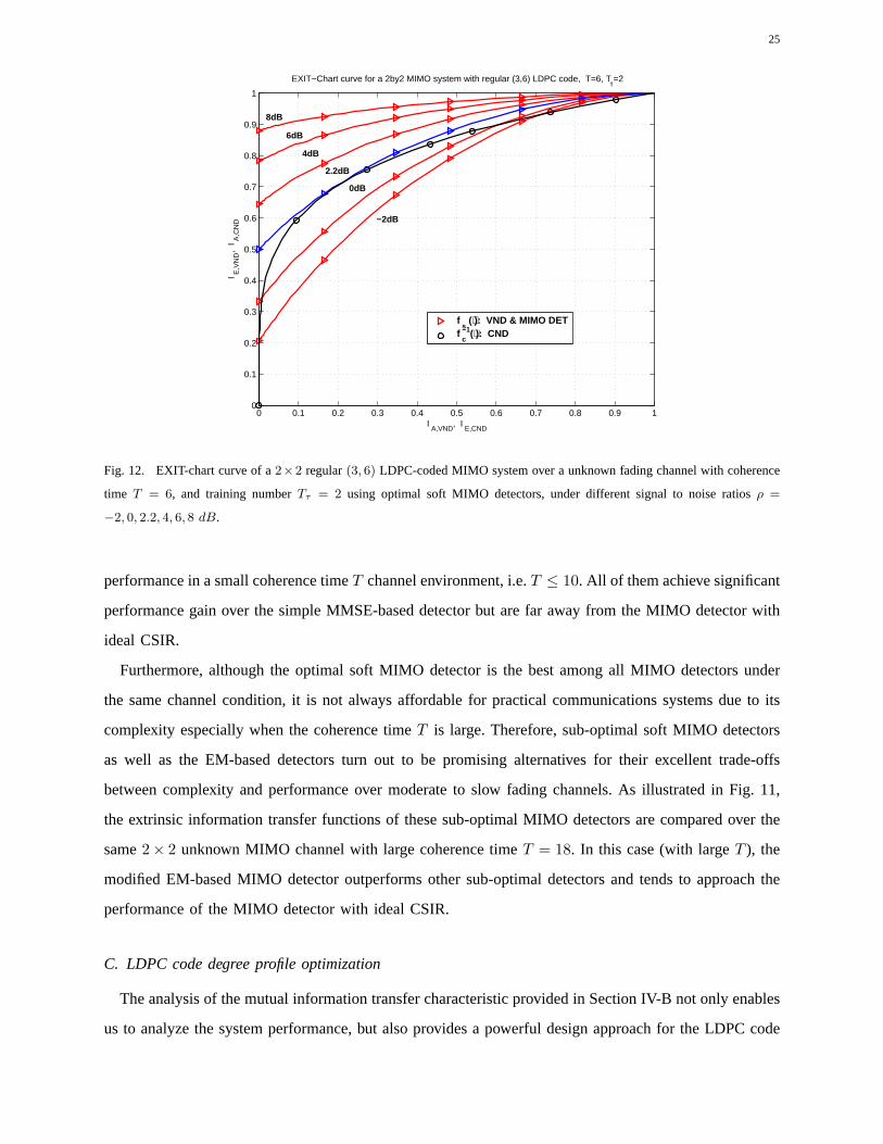
Fig. 12. EXIT-chart curve of a2×2 regular(3, 6) LDPC-coded MIMO system over a unknown fading channel with coherence
time T = 6, and training numberTτ = 2 using optimal soft MIMO detectors, under different signal to noise ratios ρ =
−2, 0, 2.2, 4, 6, 8 dB.
performance in a small coherence timeT channel environment, i.e.T ≤ 10. All of them achieve significant
performance gain over the simple MMSE-based detector but are far away from the MIMO detector with
ideal CSIR.
Furthermore, although the optimal soft MIMO detector is the best among all MIMO detectors under
the same channel condition, it is not always affordable for practical communications systems due to its
complexity especially when the coherence timeT is large. Therefore, sub-optimal soft MIMO detectors
as well as the EM-based detectors turn out to be promising alternatives for their excellent trade-offs
between complexity and performance over moderate to slow fading channels. As illustrated in Fig. 11,
the extrinsic information transfer functions of these sub-optimal MIMO detectors are compared over the
same2× 2 unknown MIMO channel with large coherence timeT = 18. In this case (with largeT ), the
modified EM-based MIMO detector outperforms other sub-optimal detectors and tends to approach the
performance of the MIMO detector with ideal CSIR.
C. LDPC code degree profile optimization
The analysis of the mutual information transfer characteristic provided in Section IV-B not only enables
us to analyze the system performance, but also provides a powerful design approach for the LDPC code
Page 26
26
0 0.1 0.2 0.3 0.4 0.5 0.6 0.7 0.8 0.9 10
0.1
0.2
0.3
0.4
0.5
0.6
0.7
0.8
0.9
1
I A,VND
, I E,CND
I E,V
ND
, I A
,CN
D
EXIT−Chart curve for a 2by2 MIMO system with optimized LDPC code, T=6, Tτ=2
f s
(⋅): VND & MIMO DET f
c −1(⋅): CND
8dB 6dB
4dB 1.3dB
0dB −2dB
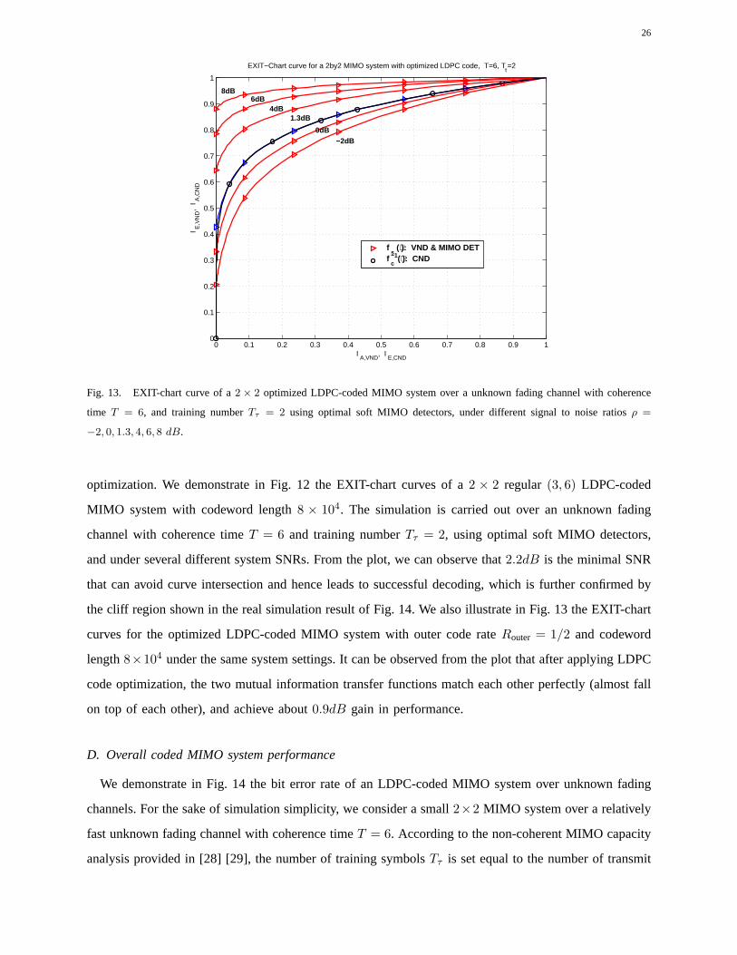
Fig. 13. EXIT-chart curve of a2 × 2 optimized LDPC-coded MIMO system over a unknown fading channel withcoherence
time T = 6, and training numberTτ = 2 using optimal soft MIMO detectors, under different signal to noise ratios ρ =
−2, 0, 1.3, 4, 6, 8 dB.
optimization. We demonstrate in Fig. 12 the EXIT-chart curvesof a 2 × 2 regular (3, 6) LDPC-coded
MIMO system with codeword length8 × 104. The simulation is carried out over an unknown fading
channel with coherence timeT = 6 and training numberTτ = 2, using optimal soft MIMO detectors,
and under several different system SNRs. From the plot, we can observe that2.2dB is the minimal SNR
that can avoid curve intersection and hence leads to successful decoding, which is further confirmed by
the cliff region shown in the real simulation result of Fig. 14. We also illustrate in Fig. 13 the EXIT-chart
curves for the optimized LDPC-coded MIMO system with outer code rateRouter = 1/2 and codeword
length8×104 under the same system settings. It can be observed from the plot that after applying LDPC
code optimization, the two mutual information transfer functions match each other perfectly (almost fall
on top of each other), and achieve about0.9dB gain in performance.
D. Overall coded MIMO system performance
We demonstrate in Fig. 14 the bit error rate of an LDPC-coded MIMOsystem over unknown fading
channels. For the sake of simulation simplicity, we consider a small2×2 MIMO system over a relatively
fast unknown fading channel with coherence timeT = 6. According to the non-coherent MIMO capacity
analysis provided in [28] [29], the number of training symbols Tτ is set equal to the number of transmit
Page 27
27
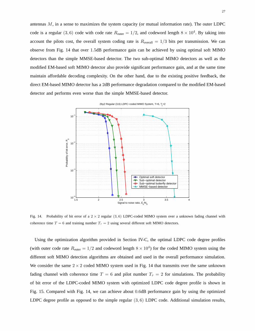
antennasM , in a sense to maximizes the system capacity (or mutual information rate). The outer LDPC
code is a regular(3, 6) code with code rateRouter = 1/2, and codeword length8 × 104. By taking into
account the pilots cost, the overall system coding rate isRoverall = 1/3 bits per transmission. We can
observe from Fig. 14 that over1.5dB performance gain can be achieved by using optimal soft MIMO
detectors than the simple MMSE-based detector. The two sub-optimal MIMO detectors as well as the
modified EM-based soft MIMO detector also provide significant performance gain, and at the same time
maintain affordable decoding complexity. On the other hand, due to the existing positive feedback, the
direct EM-based MIMO detector has a2dB performance degradation compared to the modified EM-based
detector and performs even worse than the simple MMSE-based detector.
1.5 2 2.5 3 3.5 410
−4
10−3
10−2
10−1
Signal to noise ratio, Es/N
0
Pro
babi
lity
of b
it er
ror,
Pb
2by2 Regular (3,6) LDPC−coded MIMO System, T=6, Tτ=2
Optimal soft detectorSub−optimal detectorSub−optimal butterfly detectorMMSE−based detector
Fig. 14. Probability of bit error of a2 × 2 regular(3, 6) LDPC-coded MIMO system over a unknown fading channel with
coherence timeT = 6 and training numberTτ = 2 using several different soft MIMO detectors.
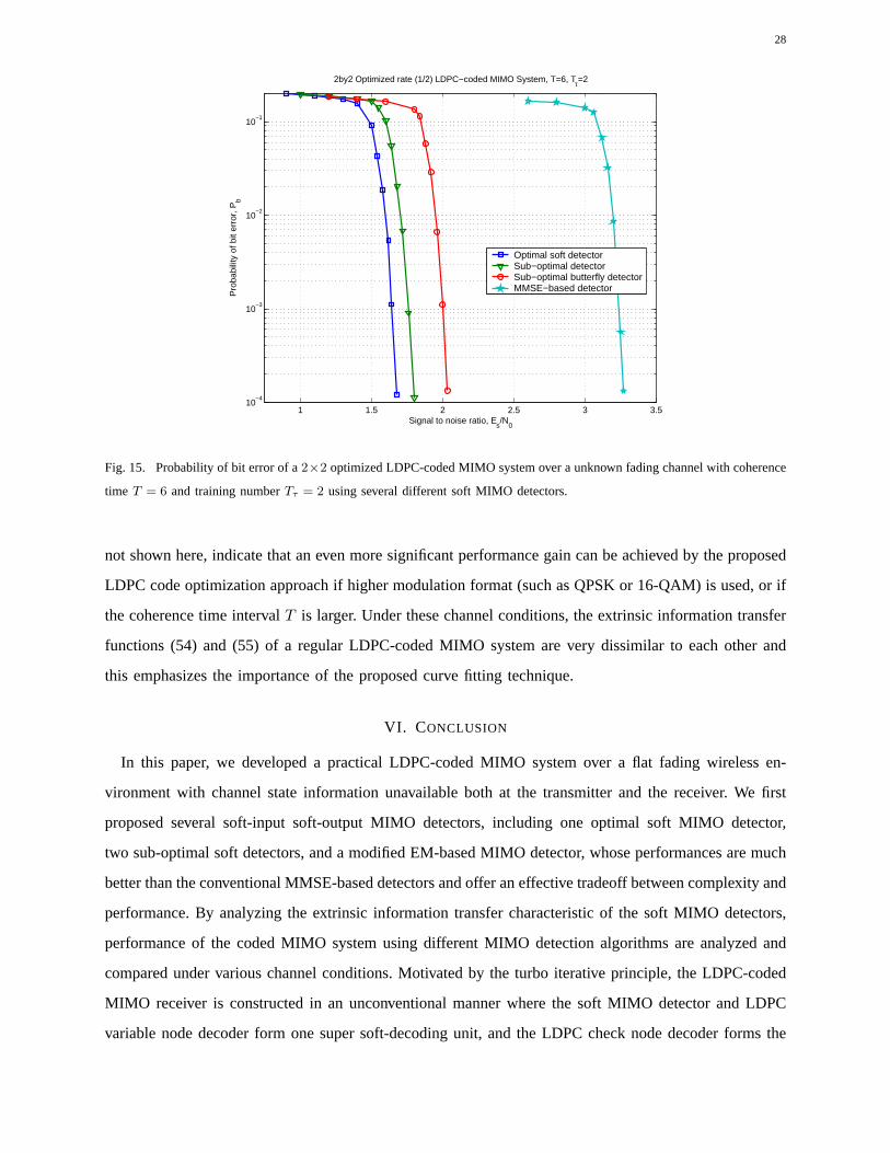
Using the optimization algorithm provided in Section IV-C, the optimal LDPC code degree profiles
(with outer code rateRouter = 1/2 and codeword length8× 104) for the coded MIMO system using the
different soft MIMO detection algorithms are obtained and used in the overall performance simulation.
We consider the same2× 2 coded MIMO system used in Fig. 14 that transmits over the same unknown
fading channel with coherence timeT = 6 and pilot numberTτ = 2 for simulations. The probability
of bit error of the LDPC-coded MIMO system with optimized LDPC code degree profile is shown in
Fig. 15. Compared with Fig. 14, we can achieve about0.6dB performance gain by using the optimized
LDPC degree profile as opposed to the simple regular(3, 6) LDPC code. Additional simulation results,
Page 28
28
1 1.5 2 2.5 3 3.510
−4
10−3
10−2
10−1
Signal to noise ratio, Es/N
0
Pro
babi
lity
of b
it er
ror,
Pb
2by2 Optimized rate (1/2) LDPC−coded MIMO System, T=6, Tτ=2
Optimal soft detectorSub−optimal detectorSub−optimal butterfly detectorMMSE−based detector
Fig. 15. Probability of bit error of a2×2 optimized LDPC-coded MIMO system over a unknown fading channel withcoherence
time T = 6 and training numberTτ = 2 using several different soft MIMO detectors.
not shown here, indicate that an even more significant performance gain can be achieved by the proposed
LDPC code optimization approach if higher modulation format (such as QPSK or 16-QAM) is used, or if
the coherence time intervalT is larger. Under these channel conditions, the extrinsic information transfer
functions (54) and (55) of a regular LDPC-coded MIMO system arevery dissimilar to each other and
this emphasizes the importance of the proposed curve fitting technique.
VI. CONCLUSION
In this paper, we developed a practical LDPC-coded MIMO systemover a flat fading wireless en-
vironment with channel state information unavailable bothat the transmitter and the receiver. We first
proposed several soft-input soft-output MIMO detectors, including one optimal soft MIMO detector,
two sub-optimal soft detectors, and a modified EM-based MIMO detector, whose performances are much
better than the conventional MMSE-based detectors and offer an effective tradeoff between complexity and
performance. By analyzing the extrinsic information transfer characteristic of the soft MIMO detectors,
performance of the coded MIMO system using different MIMO detection algorithms are analyzed and
compared under various channel conditions. Motivated by the turbo iterative principle, the LDPC-coded
MIMO receiver is constructed in an unconventional manner where the soft MIMO detector and LDPC
variable node decoder form one super soft-decoding unit, and the LDPC check node decoder forms the
Page 29
29
other component of the iterative decoding scheme. The proposed receiver structure has lower decoding
complexity and further leads to tractable EXIT functions of the component soft decoders. Based on
the obtained closed form EXIT functions, a simple and efficientLDPC code degree profile optimization
algorithm is developed with proven global optimality and guaranteed convergence from any initialization.
Finally, numerical and simulation results of the LDPC-coded MIMO system using the optimized degree
profile further confirm the advantage of using the proposed design approach for the coded MIMO system.
REFERENCES
[1] E. Telatar, “Capacity of multi-antenna Gaussian channels,”European Trans. Telecomm. (ETT), vol. 10, no. 6, pp. 585–595,
Nov 1999.
[2] G. J. Foschini, “Layered space-time architecture for wireless communication in a fading environment when using multiple
antennas,”Bell Labs Technical Journal, vol. 1, no. 2, pp. 41–59, Autumn 1996.
[3] J. H. Kotecha and A. M. Sayeed, “Transmit signal design for optimal estimation of correlated MIMO channels,”IEEE
Trans. on Signal Processing, vol. 52, pp. 546–557, Feb 2004.
[4] D. Samardzija and N. Mandayam, “Pilot-assisted estimation of MIMO fading channel response and achievable data rates,”
IEEE Trans. on Signal Processing, vol. 51, pp. 2882–2890, Nov 2003.
[5] I. Bradaric, A. P. Petropulu, and K. I. Diamantaras, “Blind MIMO FIR channel identification based on second-order spectra
correlations,” IEEE Trans. on Signal Processing, vol. 51, pp. 1668–1674, June 2003.
[6] H. Sahlin and H. Broman, “MIMO signal separation for FIR channels: A criterion and performance analysis,”IEEE Trans.
on Signal Processing, vol. 48, pp. 642–649, Mar 2000.
[7] S. Amari and J. F. Cardoso, “Blind source separation-semiparametric statistical approach,”IEEE Trans. on Signal
Processing, vol. 45, pp. 2692–2700, Nov 1997.
[8] C. Jutten and J. Heuralt, “Blind separation of sources, part I: An adaptive algorithm based on neuromimetic architecture,”
Signal Processing, July 1991.
[9] V. Tarokh and H. Jafarkhani, “A differential detection scheme for transmit diversity,” IEEE Journal on Selected Areas in
Communications, vol. 18, pp. 1169–1174, July 2000.
[10] B. L. Hughes, “Differential space-time modulation,”IEEE Trans. on Information Theory, vol. 46, pp. 2567–2578, Nov
2000.
[11] B. M. Hochwald and W. Sweldens, “Differential unitary space-timemodulation,” IEEE Trans. on Communications, vol.
48, pp. 2041–2052, Dec 2000.
[12] B. Hochwald and T. Marzetta, “Unitary space-time modulation for multiple-antenna communications in Rayleigh flat
fading,” IEEE Trans. on Information Theory, vol. 46, pp. 543–564, Mar 2000.
[13] B. M. Hochwald, T. L. Marzetta, T. J. Richardson, W. Sweldens,and R. Urbanke, “Systematic design of unitary space-time
constellations,”IEEE Trans. on Information Theory, vol. 46, pp. 1962–1973, Sept 2000.
[14] D. Agrawal, T. J. Richardson, and R. Urbanke, “Multiple-antenna signal constellations for fading channels,”IEEE Trans.
on Information Theory, vol. 47, pp. 2618–2626, Sept 2001.
[15] M. L. McCloud, M. Brehler, and M. K. Varanasi, “Signal design and convolutional coding for noncoherent space-time
communication on the block-Rayleigh-fading channel,”IEEE Trans. on Information Theory, vol. 48, pp. 1186–1194, May
2002.
Page 30
30
[16] V. Tarokh and I.-M. Kim, “Existence and construction of noncoherent unitary space-time codes,”IEEE Trans. on
Information Theory, vol. 48, pp. 3112–3117, Dec 2002.
[17] M. J. Borran, A. Sabharwal, and B. Aazhang, “On design criteria and construction of noncoherent space-time constellations,”
IEEE Trans. on Information Theory, vol. 49, pp. 2332–2351, Oct 2003.
[18] W. Zhao, G. Leus, and G. B. Giannakis, “Algebraic design of unitary space-time constellations,” inIEEE International
Conference on Communications 2003, Anchorage, AK, May 2003, pp. 3180–3184.
[19] C. N. Georghiades and J. C. Han, “Sequence estimation in the presence of random parameters via the EM algorithm,”
IEEE Trans. on Communications, vol. 45, pp. 300–308, March 1997.
[20] G. Kaleh, “Joint parameter estimation and symbol detection for linear and nonlinear unknown channels,”IEEE Trans. on
Communications, vol. 42, pp. 2406–2413, July 1994.
[21] C. Cozzo and B. L. Hughes, “Joint channel estimation and data detection in space-time communications,”IEEE Trans.
on Communications, vol. 51, pp. 1266–1270, Aug 2003.
[22] J. J. Boutros, F. Boixadera, and C. Lamy, “Bit-interleaved coded modulations for multiple-input multiple-output channels,”
in IEEE International Symposium on Spread Spectrum Techniques and Applications, Sept 2000, vol. 1, pp. 123–126.
[23] M. Gonzalez-Lopez, J. Miguez, and L. Castedo, “Turbo aided maximum likelihood channel estimation for space-time
coded systems,” inIEEE International Symposium on PIMRC 2002, Sept 2002, pp. 364–368.
[24] H. Wymeersch, F. Simoens, and M. Moeneclaey, “Code-aided joint channel estimation and frame synchronization for
MIMO systems,” inWorkshop on Signal Processing Advances in Wireless Communications (SPAWC’04), July 2004.
[25] S. ten Brink, “Convergence behavior of iteratively decoded parallel concatenated codes,”IEEE Trans. on Communications,
vol. 49, pp. 1727–1737, Oct 2001.
[26] J. Hagenauer, “The turbo principle: Tutorial introduction and stateof the art,” in IEEE International Symposium on Turbo
Codes and Related Topics, Sept 1997.
[27] S. ten Brink, G. Kramer, and A. Ashikhmin, “Design of low-densityparity-check codes for modulation and detection,”
IEEE Trans. on Communications, vol. 52, pp. 670–678, Apr 2004.
[28] B. Hassibi and B. M. Hochwald, “How much training is needed in multiple-antenna wireless links?,”IEEE Trans. on
Information Theory, vol. 49, pp. 951–963, Apr 2003.
[29] J. Zheng and B. D.Rao, “Capacity analysis of MIMO systems with unknown channel state information,” inIEEE
Information Theory Workshop 2004, San Antonio, Oct 2004.
[30] R. M. Tanner, “A recursive approach to low complexity codes,”IEEE Trans. on Information Theory, vol. 27, pp. 533–547,
Sept 1981.
[31] T. L. Marzetta and B. M. Hochwald, “Capacity of a mobile multiple-antenna communication link in Rayleigh flat fading,”
IEEE Trans. on Information Theory, vol. 45, pp. 139–157, Jan 1999.
[32] L. Wei, “Several properties of short LDPC codes,”IEEE Trans. on Communications, vol. 52, pp. 721–727, May 2004.
[33] Y. J. Ko and J. H. Kim, “Girth conditioning for construction of shortblock length irregular LDPC codes,”Electronics
Letters, vol. 40, pp. 187–188, Feb 2004.
[34] A. Ashikhmin, G. Kramer, and S. ten Brink, “Extrinsic information transfer functions: model and erasure channel
properties,” to appear in IEEE Trans. on Information Theory, 2004.


![A Massively Parallel Implementation of QC-LDPC Decoder ...gw2/pdf/sasp2011_gpu_ldpc_long.pdfQuasi-Cyclic LDPC (QC-LDPC) codes [1] have been widely used in many practical systems, such](https://static.documents.pub/doc/80x56/608577e15da5786347664f4c/a-massively-parallel-implementation-of-qc-ldpc-decoder-gw2pdfsasp2011gpuldpclongpdf.jpg)


